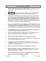
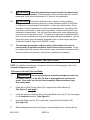
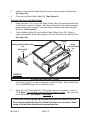
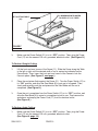
1
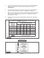
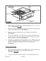
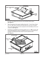
7” PORTABLE WET TILE SAW
Model 91511
ASSEMBLY AND OPERATING INSTRUCTIONS
Diamond Blade not included; sold separately.
Distributed Exclusively by Harbor Freight Tools
3491 Mission Oaks Blvd., Camarillo, CA 93011
Visit our Web site at http://www.harborfreight.com
To prevent serious injury,
Read and understand all warnings
and instructions before use.
Copyright© 2004 by Harbor Freight Tools®. All rights reserved. No
portion of this manual or any artwork contained herein may be reproduced
in any shape or form without the express written consent of Harbor Freight
Tools.
For technical questions and replacement parts, please call 1-800-444-3353
REV 08a, 09e
PRODUCT SPECIFICATIONS
Item
Electrical Requirements
Cutting Capacity
Blade Size/Type
Arbor Size
Angle Cutting Capacity
Water Compartment
Overall Dimensions
Weight
Description
120 V / 60 Hz / 3400 RPM
1/2 HP / Single Phase Motor
Start Up AMPs: 10.2
Circuit Breaker: 120V
3 Prong, Grounded, Power Cord Plug
Up to 1-1/4” Thick
7” Diamond With 5/8” Round Arbor Hole
*Must Be Rated At 3600 RPM Or Greater
(Diamond Blade not included; sold separately)
5/8” Diameter
Right Side of Table Tilts At:
15°, 30°, 45°, 60°
13” L x 6-1/4” W x 5-13/16” Deep
Maximum Water Depth: 1-1/2”
15-5/8” L x 15-3/4” W x 6-1/2” H
16.3 Pounds
Note: Sku 67111 7” Diamond Blade (wet) and Sku 67047 7” Diamond Turbo Blade (wet/dry) will
fit this Tile Saw. Both blades are sold separately and are available from Harbor Freight Tools.
UNPACKING
When unpacking, check to make sure all the parts shown on the Parts List on page 17
are included. If any parts are missing or broken, please call Harbor Freight Tools at the
number shown on the cover of this manual as soon as possible.
SAVE THIS MANUAL
You will need this manual for the safety warnings and precautions, assembly, operating,
inspection, maintenance and cleaning procedures, parts list and assembly diagram.
Keep your invoice with this manual. Write the invoice number on the inside of the front
cover. Keep this manual and invoice in a safe and dry place for future reference.
GENERAL SAFETY RULES
WARNING!
READ AND UNDERSTAND ALL INSTRUCTIONS
Failure to follow all instructions listed in the following
pages may result in electric shock, fire, and/or serious injury.
SAVE THESE INSTRUCTIONS
SKU 91511
PAGE 2
REV 07j; 09e
WORK AREA
1.
Keep your work area clean and well lit. Cluttered benches and dark areas invite accidents.
2.
Do not operate power tools in explosive atmospheres, such as in the
presence of flammable liquids, gases, or dust. Power tools create sparks which may ignite flammables. 3.
Keep bystanders, children, and visitors away while operating a power tool.
Distractions can cause you to lose control. Protect others in the work area from debris such as chips and sparks. Provide barriers or shields as needed.
PERSONAL SAFETY
1.
Stay alert. Watch what you are doing, and use common sense when
operating a power tool. Do not use a power tool while tired or under the
influence of drugs, alcohol, or medication. A moment of inattention while
operating power tools may result in serious personal injury.
2.
Dress properly. Do not wear loose clothing or jewelry. Contain long hair. Keep your hair, clothing, and gloves away from moving parts. Loose clothes, jewelry, or long hair can be caught in moving parts.
3.
Avoid accidental starting. Be sure the Power Switch is off before plugging in. Carrying power tools with your finger on the Power Switch, or plugging in power tools with the Power Switch on, invites accidents.
4.
Remove adjusting keys or wrenches before turning the power tool on. A wrench or a key that is left attached to a rotating part of the power tool may result in personal injury.
5.
Do not overreach. Keep proper footing and balance at all times. Proper footing and balance enables better control of the power tool in unexpected
situations.
6.
Use safety equipment. Always wear ANSI-approved safety goggles, a dust mask or respirator, and hearing protection.
TOOL USE AND CARE
1.
Do not force the tool. Use the correct tool for your application. The correct tool will do the job better and safer at the rate for which it is designed.
SKU 91511
PAGE 3
2.
Do not use the power tool if the Power Switch does not turn it on or off. Any tool that cannot be controlled with the Power Switch is dangerous and must be replaced.
3.
Disconnect the Power Cord Plug from the power source before making any
adjustments, changing accessories, or storing the tool. Such preventive safety measures reduce the risk of starting the tool accidentally.
4.
Store idle tools out of reach of children and other untrained persons. Tools are dangerous in the hands of untrained users.
5.
Maintain tools with care. Do not use a damaged tool. Tag damaged tools “Do not use” until repaired.
6.
Check for misalignment or binding of moving parts, breakage of parts, cracking or breakage of the Blade, and any other condition that may affect the tool’s operation. If damaged, have the tool serviced before using. Many accidents are caused by poorly maintained tools.
7.
Use only accessories that are recommended by the manufacturer for your model. Accessories that may be suitable for one tool may become hazardous when used on another tool.
SERVICE
1.
Tool service must be performed only by qualified repair personnel. Service or maintenance performed by unqualified personnel could result in a risk of injury.
2.
When servicing a tool, use only identical replacement parts. Follow instructions in the “Inspection, Maintenance, And Cleaning” section of this manual. Use of unauthorized parts or failure to follow maintenance instructions may create a risk of electric shock or injury.
ELECTRICAL SAFETY
1.
Grounded tools must be plugged into an outlet properly installed and grounded in accordance with all codes and ordinances. Never remove the grounding prong or modify the plug in any way. Do not use any adapter plugs. Check with a qualified electrician if you are in doubt as to whether the outlet is properly grounded. If the tools should electrically malfunction or break down, grounding provides a low resistance path to carry electricity away from the user.
SKU 91511
PAGE 4
2.
Double insulated tools are equipped with a polarized plug (one prong is wider than the other). This plug will fit in a polarized outlet only one way. If the plug does not fit fully in the outlet, reverse the plug. If it still does not fit, contact a qualified electrician to install a polarized outlet. Do not change the plug in any way. Double insulation
eliminates the need for the three wire grounded power cord and grounded power supply system.
3.
Avoid body contact with grounded surfaces such as pipes, radiators, ranges, and refrigerators. There is an increased risk of electric shock if your body is grounded.
4.
Do not expose power tools to external rain or wet conditions. Water entering unprotected parts of this power tool will increase the risk of electric shock.
5.
Do not abuse the Power Cord. Never use the Power Cord to carry the tools or pull the Plug from an outlet. Keep the Power Cord away from heat, oil, sharp edges, or moving parts. Replace damaged Power Cords immediately.
Damaged Power Cords increase the risk of electric shock.
6.
When operating a power tool outside, use an outdoor extension cord marked “W-A” or “W”. These extension cords are rated for outdoor use, and reduce the risk of electric shock.
GROUNDING
WARNING!
Improperly connecting the grounding wire can result in the risk of electric
shock. Check with a qualified electrician if you are in doubt as to whether the outlet
is properly grounded. Do not modify the power cord plug provided with
the tool. Never remove the grounding prong from the plug. Do not use the
tool if the power cord or plug is damaged. If damaged, have it repaired by
a service facility before use. If the plug will not fit the outlet, have a proper
outlet installed by a qualified electrician.
GROUNDED TOOLS: TOOLS WITH THREE PRONG PLUGS
1.
Tools marked with “Grounding Required” have a three wire cord and three prong grounding plug. The plug must be connected to a properly grounded outlet. If the tool should electrically malfunction or break down, grounding provides a low SKU 91511
PAGE 5
resistance path to carry electricity away from the user, reducing the risk of electric
shock. (See Figure A.)
2.
The grounding prong in the plug is connected through the green wire inside the cord to the grounding system in the tool. The green wire in the cord must be the only wire connected to the tool’s grounding system and must never be attached to an electrically “live” terminal. (See Figure A.)
3.
Your tool must be plugged into an appropriate outlet, properly installed and grounded in accordance with all codes and ordinances. The plug and outlet should look like those in the following illustration. (See Figure A.)
FIGURE A
EXTENSION CORDS
1.
Grounded tools require a three wire extension cord. Double Insulated tools can use either a two or three wire extension cord.
2.
As the distance from the supply outlet increases, you must use a heavier gauge extension cord. Using extension cords with inadequately sized wire causes a serious drop in voltage, resulting in loss of power and possible tool damage. (See Figure B, next page.)
3.
The smaller the gauge number of the wire, the greater the capacity of the cord. For example, a 14 gauge cord can carry a higher current than a 16 gauge cord. (See Figure B.)
4.
When using more than one extension cord to make up the total length, make sure each cord contains at least the minimum wire size required. (See Figure B.)
SKU 91511
PAGE 6
5.
If you are using one extension cord for more than one tool, add the nameplate
amperes and use the sum to determine the required minimum cord size.
(See Figure B.)
6.
If you are using an extension cord outdoors, make sure it is marked with the
suffix “W-A” (“W” in Canada) to indicate it is acceptable for outdoor use.
7.
Make sure your extension cord is properly wired and in good electrical condition.
Always replace a damaged extension cord or have it repaired by a qualified
electrician before using it.
8.
Protect your extension cords from sharp objects, excessive heat, and damp or
wet areas.
RECOMMENDED MINIMUM WIRE GAUGE FOR EXTENSION
CORDS* (120/240 VOLT)
EXTENSION CORD LENGTH
(at full load)
25’
50’
75’
100’
150’
NAMEPLATE
AMPERES
0 – 2.0
18
18
18
18
16
2.1 – 3.4
18
18
18
16
14
3.5 – 5.0
18
18
16
14
12
5.1 – 7.0
18
16
14
12
12
7.1 – 12.0
18
14
12
10
-
12.1 – 16.0
14
12
10
-
-
12
10
-
-
-
16.1 – 20.0
* Based on limiting the line voltage drop to five volts at
150% of the rated amperes.
TABLE A
FIGURE B
SYMBOLOGY
Double Insulated
V~
A
FIGURE C
no
xxxx/min.
SKU 91511
Canadian Standards
Association
Underwriters
Laboratories, Inc.
Volts Alternating
Current
Amperes
No Load Revolutions
Per Minute (RPM)
PAGE 7
SPECIFIC SAFETY RULES
1.
Maintain labels and nameplates on the Wet Tile Saw. These carry important
information. If unreadable or missing, contact Harbor Freight Tools for a replacement.
2.
DANGER! Keep hands and fingers away from cutting area and Saw Blade. Use a appropriate push stick (not included) whenever possible.
3.
Check Blade Guard for proper upward/downward movement before each use. Do not operate the Wet Tile Saw if the Blade Guard does not move freely. Never clamp or tie the Blade Guard into the upward position. If the Wet Tile Saw is accidentally dropped, the Blade Guard may be bent. Raise the Blade Guard and make sure it moves freely and does not touch the Saw Blade or any other part of the Saw, in all angles and depths of cut.
4.
Always use Diamond Blades (sold separately) with 7” diameter, 5/8” round arbor hole, and rated at a minimum 3,600 RPM. Blades that do not match the
mounting hardware of the Wet Tile Saw or that are rated at less than the required
minimum RPM will run eccentrically causing loss of control or may fly off the Saw.
5.
Use the Wet Tile Saw only for cutting ceramic tile, quarry tile, marble, terra cotta, and slate with a maximum thickness of 1-1/4”.
6.
Do not use the Wet Tile Saw for cutting metals, or for cutting curves. This may cause the Saw Blade to break, and reduce its service life.
7.
Make sure the Saw Blade remains wet at all times while cutting.
8.
Always keep the water level at the recommended level (1-1/2” deep). Do not overfill or allow the Wet Tile Saw to run dry.
9.
Avoid splashing water on the Motor, Power Switch, or any electrical
component. Make sure to stand on a dry, insulated surface, such as a rubber
mat, while using this Wet Tile Saw.
10.
Make sure to clean the water reservoir thoroughly after each use.
11.
Never use damaged or incorrect Saw Blade washers or nuts. The Saw Blade’s washers and nut were specially designed for your Saw, for optimum performance and safety of operation.
12.
To avoid accidental injury, always wear heavy duty work gloves and long sleeved work shirt when changing a Saw Blade.
SKU 91511
PAGE 8
Rev 07j; 09e
13.
Before using the Wet Tile Saw, make sure the Saw Blade is properly mounted on the Saw Spindle. Make sure the Saw Blade is balanced, and is not cracked or bent.
14.
The Saw Blade will become hot while cutting. Allow the Saw Blade to completely cool before touching.
15.
Allow the Saw Blade to spin up to full speed before feeding a workpiece into it. When turning off the Saw, allow the Saw Blade to spin down and stop on its own. Do not press against the Saw Blade to stop it.
16.
Do not force the workpiece into the Saw Blade when cutting. Apply
moderate pressure, allowing the Saw Blade to cut without being forced.
17.
Turn off the Wet Tile Saw and allow the Saw Blade to stop on its own if the Saw Blade is to be backed out of an uncompleted cut.
18.
Never attempt to remove material stuck in the moving parts of the Wet Tile Saw while it is plugged in and running.
19.
When cutting a large workpiece, make sure its entire length is properly supported. If necessary, use a roller stand (not included) with larger workpieces.
20.
Never stand on the Wet Tile Saw. Serious injury could result if the Wet Tile Saw is tipped or if the rotating Saw Blade is accidently contacted.
21.
Industrial applications must follow OSHA requirements.
22.
For your safety: In extreme working conditions, sensors in the Wet Tile Saw
will automatically switch off the Motor to prevent overheating. In this event, turn
the Power Switch to its “OFF” position. Wait five minutes or until the Motor has
cooled. Depress the Circuit Breaker. Then, turn the Power Switch to its “ON”
position to resume cutting.
23.
Always turn off the Wet Tile Saw and unplug the Power Cord from its electrical outlet before changing accessories or performing any inspection, maintenance, or cleaning procedures.
24.
Use the right tool or attachment for the job. Do not attempt to force a small tool or attachment to do the work of a larger industrial tool or attachment. There are certain applications for which this product was designed. It will do the job better and more safely at the rate for which it was intended. Do not modify
this product, and do not use this product for a purpose for which it was not
intended.
SKU 91511
PAGE 9
25.
WARNING! People with pacemakers should consult their physician(s) before using this product. Electromagnetic fields in close proximity to a heart pacemaker could cause interference to or failure of the pacemaker.
26.
WARNING! Some dust created by power sanding, sawing, grinding,
drilling, and other construction activities, contain chemicals known (to the State
of California) to cause cancer, birth defects or other reproductive harm. Some
examples of these chemicals are: lead from lead-based paints, crystalline silica
from bricks and cement or other masonry products, arsenic and chromium from
chemically treated lumber. Your risk from these exposures varies, depending on
how often you do this type of work. To reduce your exposure to these chemicals:
work in a well ventilated area, and work with approved safety equipment, such as
those dust masks that are specially designed to filter out microscopic particles.
(California Health & Safety Code 25249.5, et seq.)
27.
The warnings, precautions, and instructions discussed in this manual
cannot cover all possible conditions and situations that may occur. It must
be understood by the operator that common sense and caution are factors which
cannot be built into this product, but must be supplied by the operator.
ASSEMBLY INSTRUCTIONS
NOTE: For additional references to the parts listed in the following pages, refer to the
Assembly Diagram on page 17.
To Remove And Install The Saw Blade:
1.
WARNING! Prior to performing any assembly procedures, make sure the Power Cord (17) of the Wet Tile Saw is unplugged from its electrical outlet. Also, make sure the unit has completely cooled and wear heavy duty work gloves.
2.
Open the Left Side Cutting Table (26) to expose the old Saw Blade (6).
(See Figure D, next page.)
3.
Using the accessory Wrench (33), remove the Blade Lock Nut (27) by unscrewing
it in a clockwise direction. (See Figure D.)
4.
Once the Blade Lock Nut (27) is removed, remove the Outer Washer (28).
(See Figure D.)
5.
While wearing heavy duty work gloves to avoid accidental cuts, remove the old
SKU 91511
PAGE 10
Saw Blade (6) from the Spindle of the Wet Tile Saw. Then, install a new diamond
Saw Blade with a 7” diameter, 5/8” round arbor hole, and rated at a minimum
3,600 RPM. (See Figure D.)
6.
NOTE: When installing the new Saw Blade (6), make sure the directional arrow shown on the Saw Blade is pointing toward the front of the Wet Tile Saw.
(See Figure D.)
7
Replace the Outer Washer (28). Then, firmly tighten the Blade Lock Nut (27)
counterclockwise to secure the Saw Blade (6) in place. (See Figure D.)
WING NUT
(3)
BLADE GUARD
(2)
WING NUT SCREW
(1)
GUARD SUPPORT
(4)
GUARD SUPPORT SCREW
(5)
SAW BLADE
(6)
OUTER WASHER
(28)
BLADE LOCK NUT
(27)
LEFT CUTTING TABLE
(26)
FIGURE D
To Attach The Saw Blade Guard:
1.
Align the mounting hole in the Guard Support (4) with the mounting hole in the inner edge of the frame of the Wet Tile Saw. Then secure the Guard Support to the frame, using one Guard Support Screw (5). (See Figure D.)
2.
Secure the Blade Guard (2) to the top portion of the Guard Support (4), using one Wing Nut Screw (1) and one Wing Nut (3). (See Figure D.)
SKU 91511
PAGE 11
3.
Check to make sure the Blade Guard (2) moves freely upward and downward.
(See Figure D.)
4.
Close the Left Side Cutting Table (26). (See Figure D.)
To Attach The Fence And Miter Guide:
1.
Place the Fence (11) on top of the Right Cutting Table (10) and clamp both ends of the Fence to secure it in place. The Fence is marked in both inches and centi
meters to make cuts accurate. The Fence may be used on either side of the Saw Blade (6). (See Figure E.)
2.
Slide the Miter Guide (24) into the Miter Guide Sliding Track (29). Check to make sure the Miter Guide slides freely to the front and rear of the Wet Tile Saw. (See Figure E.)
FENCE
(11)
MITER GUIDE SLIDING TRACK
(29)
MITER GUIDE
(24)
RIGHT
CUTTING TABLE
(10)
FIGURE E
OPERATING INSTRUCTIONS
1.
The Power Cord (17) is stored underneath the Wet Tile Saw. Take out the Power Cord, but DO NOT plug it into an electrical outlet.
2.
Raise the Left Cutting Table (26). Then fill the reservoir with water to a level of
1-1/2” deep. Do not overfill or allow the Wet Tile Saw to run dry. Then, close the Left Cutting Table. (See Figure F, next page.)
Check Blade Guard for proper upward/downward movement before each use.
Do not operate the Wet Tile Saw if the Blade Guard does not move freely. Never
clamp or tie the Blade Guard into the upward position.
SKU 91511
PAGE 12
FILL RESERVOIR WITH WATER
TO LEVEL OF 1-1/2” DEEP.
LEFT CUTTING TABLE
(26)
FIGURE F
3.
Make sure the Power Switch (21) is in its “OFF” position. Then, plug the Power Cord (17) into the nearest 120 volt, grounded, electrical outlet. (See Figure G.)
To Perform Straight Cutting:
1.
Lift the front and rear Levers of the Fence (11). Slide the Fence along the Table to the left or right until the desired width of cut is aquired as indicated on the Fence Scale. Then, lower the front and rear Levers of the Fence to lock the Fence in place. (See Figure G, next page.)
2.
Place the workpiece flush against the Fence (11). Turn the Power Switch (21) to its “ON” position, and allow the Saw Blade (6) to spin up to full speed. Then,
slowly and carefully push the workpiece into the Saw Blade until the cut is
completed. (See Figure G.)
3.
Once the cut is completed turn the Power Switch (21) to its “OFF” position, and allow the Saw Blade (6) to come to a complete stop on its own. Then remove the workpiece, and unplug the Power Cord (17) from its electrical outlet.
(See Figure G.)
To Perform Angle Cutting:
1.
Make sure the Power Switch (21) is in its “OFF” position. Then, plug the Power Cord (17) into the nearest 120 volt, grounded, electrical outlet.
(See Figure H, page 15.)
SKU 91511
PAGE 13
WORKPIECE
(NOT INCLUDED)
FENCE
(11)
FENCE LEVER
FENCE SCALE
FIGURE G
FENCE LEVER
POWER SWITCH
(21)
2.
Raise the Right Cutting Table (10) to the desired angle of cut (i.e., 15°, 30°, 45°,
or 60° ). (See Figure next page.)
3.
Place the two Stands underneath the Right Cutting Table (10) into the grooves to hold the Cutting Table in position. (See Figure H.)
4.
Place the workpiece finished side down onto the Right Cutting Table (10).
(See Figure H.)
5.
Turn the Power Switch (21) to its “ON” position, and allow the Saw Blade (6) to spin up to full speed. Then, slowly and carefully push the workpiece into the Saw Blade until the cut is completed. (See Figure H.)
6.
Once the cut is completed turn the Power Switch (21) to its “OFF” position, and allow the Saw Blade (6) to come to a complete stop on its own. Then remove the workpiece, and unplug the Power Cord (17) from its electrical outlet.
(See Figure H.)
To Perform Miter Cutting:
1.
Make sure the Power Switch (21) is in its “OFF” position. Then, plug the Power Cord (17) into the nearest 120 volt, grounded, electrical outlet.
(See Figure I, next page.)
2.
Loosen the Lock Knob on the Miter Guide (24). Then select the degree of cut
SKU 91511
PAGE 14
RIGHT CUTTING TABLE
(10)
WORKPIECE
(NOT INCLUDED)
STAND
POWER
SWITCH
(21)
FIGURE H
(0° to 60°) and tighten the Lock Knob to lock the Miter Guide in place.
(See Figure I.)
3.
Place the workpiece flush against the Miter Guide (24). Turn the Power Switch (21) toits “ON” position, and allow the Saw Blade (6) to spin up to full speed. Then, slowly and carefully push the workpiece into the Saw Blade until the cut is completed. (See Figure I.)
4.
Once the cut is completed turn the Power Switch (21) to its “OFF” position, and allow the Saw Blade (6) to come to a complete stop on its own. Then remove the workpiece, and unplug the Power Cord (17) from its electrical outlet.
(See Figure I.)
WORKPIECE
(NOT INCLUDED)
MITER GUIDE
(24)
POWER SWITCH
(21)
FIGURE I
SKU 91511
PAGE 15
INSPECTION, MAINTENANCE, AND CLEANING
1.
WARNING! Always make sure the Power Switch (21) is in its “OFF”
position, and unplug the Power Cord (17) from its 120 volt electrical outlet
before performing any inspection, adjustments, maintenance, or cleaning.
2.
Before each use, inspect the general condition of the Wet Tile Saw. Check for
loose screws, misalignment or binding of moving parts, cracked or broken parts,
damaged electrical wiring, loose, cracked, or bent Saw Blade (6), and any other
condition that may affect its safe operation. If abnormal noise or vibration occurs,
have the problem corrected before further use.
Do not use damaged equipment.
3.
Daily: With a soft brush, cloth, or vacuum, remove all dust and debris from the exterior surfaces of the Wet Tile Saw. Clean the water reservoir thoroughly after each use.
4.
When storing, always store the Wet Tile Saw in a safe, clean, dry location.
5.
Repairs should only be performed by a qualified service technician.
PLEASE READ THE FOLLOWING CAREFULLY
THE MANUFACTURER AND/OR DISTRIBUTOR HAS PROVIDED THE PARTS LIST AND ASSEMBLY
DIAGRAM IN THIS MANUAL AS A REFERENCE TOOL ONLY. NEITHER THE MANUFACTURER OR
DISTRIBUTOR MAKES ANY REPRESENTATION OR WARRANTY OF ANY KIND TO THE BUYER THAT
HE OR SHE IS QUALIFIED TO MAKE ANY REPAIRS TO THE PRODUCT, OR THAT HE OR SHE IS
QUALIFIED TO REPLACE ANY PARTS OF THE PRODUCT. IN FACT, THE MANUFACTURER AND/OR
DISTRIBUTOR EXPRESSLY STATES THAT ALL REPAIRS AND PARTS REPLACEMENTS SHOULD BE
UNDERTAKEN BY CERTIFIED AND LICENSED TECHNICIANS, AND NOT BY THE BUYER. THE BUYER
ASSUMES ALL RISK AND LIABILITY ARISING OUT OF HIS OR HER REPAIRS TO THE ORIGINAL
PRODUCT OR REPLACEMENT PARTS THERETO, OR ARISING OUT OF HIS OR HER INSTALLATION
OF REPLACEMENT PARTS THERETO.
SKU 91511
PAGE 16
PARTS LIST
LIST
Part #
1
2
3
4
5
6
7
8
9
10
11
12
13
14
15
16
17
Description
Screw
blade guard
Wing nut
guard Support
Screw
Continuous rim blade (7”)
inner Washer
rubber ring
magnet
right Cutting Table (adjustable)
Fence
Frame
Carrying Handle
motor
motor Screw
motor bottom base Screw
power Cord
Qty.
1
1
1
1
1
1
1
1
4
1
1
1
1
1
4
4
1
Part #
18
19
20
21
22
23
24
26
27
28
29
30
31
32
33
NOTE: Some parts are listed and
shown for illustration purposes only,
and are not available individually as
replacement parts.
SKU
SKu 91511
91511
PAGE
page 17
17
Description
motor bottom base
electrical Cord Fixed Head
Capacitor
power Switch
rubber Stand Screw
rubber Stand
miter guide
left Cutting Table
blade lock nut
outer Washer
miter guide Sliding Track
Sliding Track Screw
Circuit breaker
Circuit breaker Cover
Wrench
Qty.
1
1
1
1
4
4
1
1
1
1
1
3
1
1
1
Limited 1 year / 90 Day warranty
Harbor Freight Tools Co. makes every effort to assure that its products meet high
quality and durability standards, and warrants to the original purchaser that for a period
of ninety days from date of purchase that the engine/motor, the belts (if so equipped),
and the blades (if so equipped) are free of defects in materials and workmanship. Harbor
Freight Tools also warrants to the original purchaser, for a period of one year from date
of purchase, that all other parts and components of the product are free from defects in
materials and workmanship (90 days if used by a professional contractor or if used as rental
equipment). This warranty does not apply to damage due directly or indirectly, to misuse,
abuse, negligence or accidents, repairs or alterations outside our facilities, normal wear and
tear, or to lack of maintenance. We shall in no event be liable for death, injuries to persons
or property, or for incidental, contingent, special or consequential damages arising from
the use of our product. Some states do not allow the exclusion or limitation of incidental or
consequential damages, so the above limitation of exclusion may not apply to you. This
warranty is expressly in lieu of all other warranties, express or
implied, including the warranties of merchantability and fitness.
To take advantage of this warranty, the product or part must be returned to us with
transportation charges prepaid. Proof of purchase date and an explanation of the complaint
must accompany the merchandise. If our inspection verifies the defect, we will either
repair or replace the product at our election or we may elect to refund the purchase price
if we cannot readily and quickly provide you with a replacement. We will return repaired
products at our expense, but if we determine there is no defect, or that the defect resulted
from causes not within the scope of our warranty, then you must bear the cost of returning
the product.
This warranty gives you specific legal rights and you may also have other rights
which vary from state to state.
3491 Mission Oaks Blvd. • PO Box 6009 • Camarillo, CA 93011 • (800) 444-3353
SKU 91511
PAGE 18
Rev 09e