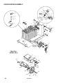
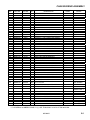
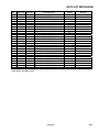
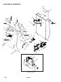
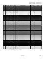
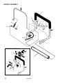
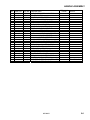
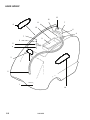
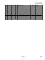
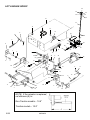
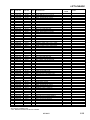
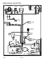
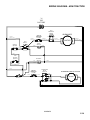
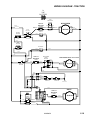
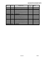
1
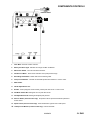
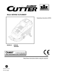
LIGHTNING
BATTERY POWERED HIGH SPEED BURNISHER
Operating Instructions (ENG)
Bedienungsanleitung (GER)
MODEL:
L20
10027100
L20T
10027110
Read these instructions before operating the machine.
Bitte lesen Sie diese Anleitungen, bevor Sie die Maschine in Gebrauch nehmen
86038450 - BE 07/02/12
PRV NO. 98753
MACHINE DATA LOG
Warranty Registration
Thank you for purchasing a Windsor product. Warranty registration is quick and easy.
Your registration will allow us to serve you better over the lifetime of the product.
To register your product go to:
www.windsorind.com/WarrantyRegistration.aspx
For customer assistance:
1-800-444-7654
2ENG
86038450
TABLE OF CONTENTS
Machine Data Log. ............................................... 2
Table of Contents ................................................. 3
HOW TO USE THIS MANUAL
How to use this Manual. ....................................... 1-1
SAFETY
Important Safety Instructions ............................... 2-1
Hazard Intensity Level.......................................... 2-2
GROUP PARTS LIST
Chassis/Drive Assembly Group. .......................... 5-1
Deck Lift Mechanism. ........................................... 5-3
Electrical Controls Group ..................................... 5-5
Handle Assembly ................................................. 5-7
Hood Group. ......................................................... 5-9
Lift Linkage Group. ............................................. 5-11
Wiring Schematic (Non-traction). ....................... 5-13
Wiring Schematic (Traction). .............................. 5-15
Suggested Spare Parts ...................................... 5-18
Notes .................................................................. 5-19
OPERATIONS
Components/Controls .......................................... 3-1
Machine Operation. .............................................. 3-2
Pre-Run Machine Inspection ............................ 3-2
Operating the Machine. ..................................... 3-2
Filter Bag. .......................................................... 3-2
Dust Control Skirt .............................................. 3-2
MAINTENANCE
Battery Information. .............................................. 4-1
Battery Connection........................................... 4-1
Battery Maintenance. ....................................... 4-1
Battery Charging Procedure. ........................... 4-1
Maintenance. ........................................................ 4-2
Weekly Maintenance. ........................................ 4-2
4 to 6 Month Maintenance ................................ 4-2
Ending Work Periods. ....................................... 4-2
Shunt Adjustments. ........................................... 4-2
Shaft Adjustment............................................... 4-2
Lubrication. ........................................................... 4-3
Service Schedule ................................................. 4-3
Machine Troubleshooting. .................................... 4-4
86038450
3ENG
HOW TO USE THIS MANUAL
This manual contains the following sections:
-
The PARTS LIST section contains assembled parts
illustrations and corresponding parts list. The parts
lists include a number of columns of information:
HOW TO USE THIS MANUAL
SAFETY
OPERATIONS
MAINTENANCE
PARTS LIST
-
The HOW TO USE THIS MANUAL section will tell
you how to find important information for ordering
correct repair parts.
-
Parts may be ordered from authorized dealers.
When placing an order for parts, the machine model
and machine serial number are important. Refer to
the MACHINE DATA box which is filled out during
the installation of your machine. The MACHINE
DATA box is located on the inside of the front cover
of this manual.
-
-
REF – column refers to the reference
number on the parts illustration.
PART NO. – column lists the part
number for the part.
PRV NO. - reference number.
QTY – column lists the quantity of the
part used in that area of the machine.
DESCRIPTION – column is a brief
description of the part.
SERIAL NO. FROM – column indicates
the first machine the part number is
applicable to. When the machine design
has changed, this column will indicate
serial number of applicable machine.
The main illustration shows the most
current design of the machine. The
boxed illustrations show older designs.
NOTES – column for information not
noted by the other columns.
NOTE: If a service or option kit is installed on your
machine, be sure to keep the KIT INSTRUCTIONS
which came with the kit. It contains replacement
parts numbers needed for ordering future parts.
NOTE: The number on the lower left corner of the
front cover is the part number for this manual.
The model and serial number of your machine is on
the bottom back-end of the machine.
The SAFETY section contains important information
regarding hazard or unsafe practices of the
machine. Levels of hazards is identified that could
result in product or personal injury, or severe injury
resulting in death.
The OPERATIONS section is to familiarize the
operator with the operation and function of the
machine.
The MAINTENANCE section contains preventive
maintenance to keep the machine and its
components in good working condition. They are
listed in this general order:
-
Batteries
Maintenance
Shunt Adjustments
Shaft Adjustment
Lubrication
Troubleshooting
1-1ENG
86038450
IMPORTANT SAFETY INSTRUCTIONS
When using an battery powered appliance, basic precaution
must always be followed, including the following:
READ ALL INSTRUCTIONS BEFORE USING THIS MACHINE.
To reduce the risk of fire, electric shock, or injury:
Use only indoors. Do not use outdoors or expose to rain.
Use only as described in this manual. Use only manufacturer’s recommended components and
attachments.
If the machine is not working properly, has been dropped, damaged, left outdoors, or dropped into
water, return it to an authorized service center.
Do not operate the machine with any openings blocked. Keep openings free of debris that may reduce
airflow.
This machine is not suitable for picking up hazardous dust.
Machine can cause a fire when operating near flammable vapors or materials. Do not operate this
machine near flammable fluids, dust or vapors.
This machine is suitable for commercial use, for example in hotels, schools, hospitals,
factories, shops and offices for more than normal housekeeping purposes.
Maintenance and repairs must be done by qualified personnel.
If foam or liquid comes out of machine, switch off immediately.
Disconnect battery before cleaning or servicing.
Before the machine is discarded, the batteries must be removed and properly disposed of.
Make sure all warning and caution labels are legible and properly attached to the machine.
During operation, attention shall be paid to other persons, especially children.
Before use all covers and doors shall be put in the positions specified in the instructions.
When leaving unattended, secure against unintentional movement.
The machine shall only be operated by instructed and authorized persons.
When leaving unattended, switch off or lock the main power switch to prevent unauthorized use.
Only chemicals recommended by the manufacturer shall be used.
This appliance has been designed for use with the brushes specified by the manufacturer. The fitting
of other brushes may affect its safety.
Do not use on surfaces having a gradient exceeding 2% unless the optional parking brake is installed
on the machine.
SAVE THESE INSTRUCTIONS
86038450
2-1ENG
HAZARD INTENSITY LEVEL
The following symbols are used throughout this guide as indicated in their descriptions:
HAZARD INTENSITY LEVEL
There are three levels of hazard intensity identified by signal words -WARNING and CAUTION and FOR
SAFETY. The level of hazard intensity is determined by the following definitions:
! WARNING
WARNING - Hazards or unsafe practices which COULD result in severe personal injury or death.
A g6s h y T
CAUTION - Hazards or unsafe practices which could result in minor personal injury or product or property
damage.
FOR SAFETY: To Identify actions which must be followed for safe operation of equipment.
Report machine damage or faulty operation immediately. Do not use the machine if it is not in proper operating
condition. Following is information that signals some potentially dangerous conditions to the operator or the
equipment. Read this information carefully. Know when these conditions can exist. Locate all safety devices on
the machine. Please take the necessary steps to train the machine operating personnel.
FOR SAFETY:
DO NOT OPERATE MACHINE:
Unless Trained and Authorized.
Unless Operation Guide is Read and understood.
In Flammable or Explosive areas.
In areas with possible falling objects.
WHEN SERVICING MACHINE:
Avoid moving parts. Do not wear loose clothing; jackets, shirts, or sleeves when working on the
machine. Use Windsor approved replacement parts.
! WARNING
Batteries emit hydrogen gas. Explosion or fire can result. Keep sparks and open flame away. Keep
solution tank in raised position when charging. Keep sparks and flames away from the batteries. Do not
smoke around batteries.
! WARNING
Disconnect batteries before working on machine. Only qualified personnel should work inside machine.
Always wear eye protection and protective clothing when working on or near batteries. Avoid skin contact
with the acid contained in the batteries.
! WARNING
Never allow metal to lie across battery tops.
2-2ENG
86038450
COMPONENTS/CONTROLS
13
12
1.
Hour Meter. Records machine use time.
2.
Battery Condition Light. Indicates the charge condition of batteries.
3.
Main Power Switch. Turns On and Off the machine.
4.
Pad Pressure Meter. “Green Area” indicates correct pad pressure range.
5.
Burnishing Head Switch. Raises and lowers burnishing head.
6.
3 Amp Circuit Breaker. Thermal circuit breaker protects lift mechanism. Press to reset.
7.
Main Handle.
8.
Handle Adjustment Lever.
9.
Breaker. 60 amp magnetic circuit breaker, protects pad driver motor. Press to reset.
10. Pad Motor Switch Bar. Raising bar turns on pad driver motor.
11. Pad Adjustment Knob. Rotating knob adjusts pad pressure.
12. Reverse Button (Traction model only). Propel bar must be squeezed and button pushed for
reverse travel.
13. Speed Control (Traction model only). Knob rotated left to right for slow to fast speed.
14. 15 Amp Circuit Breaker (Traction model only). Protects transaxle.
86038450
3-1 ENG
MACHINE OPERATION
PRE-RUN MACHINE INSPECTION
1. Disconnect the battery charger. (See battery
charging procedure).
2. Close the cover.
3. To raise the deck: Turn on the main power
switch and press the burnishing head switch.
4. Turn or install a new burnishing pad as needed.
NOTE: Pad lock has left hand threads. To
loosen turn clockwise.
FILTER BAG
The filter bag is accessed under the cover.
DUST CONTROL SKIRT
Replace skirt (86007290 – PRV NO. 730017) when
worn, torn, or damaged in any way that allows dust
to escape.
5. Check wheels and other pivot points for proper
lubrication.
OPERATING THE MACHINE
1. If using a machine that is already set up, check
to make sure the pad is properly installed.
2. Adjust the operating control handle to a
comfortable position using the handle lock lever.
3. Turn on the main power switch.
4. Lower or raise deck by pressing burnishing head
switch.
5. The pad motor will only run when the burnishing
head is lowered to within 3 inches of the floor.
6. The drive controls are shown on page 3-1.
7. The pad pressure is adjusted using the knob at
center of panel. The operator monitors the amp
draw using the meter located on the control
panel and ensures that the needle remains in
the “green” operating
range. (See page 3-1, #4 & 11).
To prevent possible damage to the floor surface,
always keep the machine moving while the pad
is spinning.
8. When the pad motor switch bar is squeezed, the
pad motor runs.
9. Return the machine to the battery charger when
the battery light indicator light is amber. Do not
operate machine when indicator is flashing red.
3-2ENG
86038450
BATTERY INFORMATION
CHARGE BATTERIES IN A WELL-VENTILATED
AREA WITH DECK DOWN AND COVER OPEN.
1. Use a 36 volt, 20 amp maximum output, D.C.
charger that turns itself off, when batteries are
fully charged. The charger must have a
connector that matches the machine battery
connection.
2. Read the instructions and warnings provided by
the battery charger manufacturer.
3. Set the charger in a well-ventilated area on a
level surface. Make sure cords will easily reach
outlets on both machine and wall.
4. Connect charger to D.C. outlet on machine
first.
5. Connect the A.C. power cord to properly
grounded wall socket. NEVER MAKE THE A.C.
CONNECTION FIRST, HAZARDOUS SPARKS
MAY RESULT.
BATTERY MAINTENANCE
1. When cleaning batteries use a solution of baking
soda and water. (Do not allow cleaning fluid to
enter inside battery cells.)
6. After the batteries are completely charged
disconnect the charger from the A.C. wall
socket.
7. Once the charger is disconnected from the A.C.
wall socket, it is safe to disconnect the charger
from the machine.
2. Keep a proper electrolyte level in battery cells.
3. Wipe down the battery tops at least once a
week. If a cell should accidentally overflow,
clean immediately.
4. Test battery condition with a hydrometer at least
once a week.
8. When the batteries are fully charged, check the
electrolyte level by removing, the caps on top of
the batteries. If necessary fill the cells with
distilled water as shown in the diagram below.
Be careful not to overfill cells.
5. Ensure that all connections are tight and that all
corrosion is removed.
6. Every 4 to 6 months remove batteries from the
machine and clean the battery compartment.
BATTERY CHARGING PROCEDURE
Charge the batteries once the amber charge level
light comes on. The amber light indicates that there
is about 20% charge left in the batteries. Do not let
the batteries completely drain before charging.
Avoid charging the batteries before the amber light
comes on. The machine will run for hours on fully
charged, well maintained batteries.
DO NOT SMOKE, HAVE OPEN FLAMES, OR
SPARKS NEAR BATTERIES AT ANY TIME.
WEAR EYE PROTECTION AND PROTECTIVE
CLOTHING WHEN WORKING WITH BATTERIES.
86038450
4-1ENG
MAINTENANCE
WEEKLY MAINTENANCE
1. Use a hydrometer to check the condition of each
battery cell.
2. Check battery cable clamps. Ensure clamps are
tight on battery terminals.
3. Clean tops of batteries with a wet cloth and a
solution of water and baking soda. Wipe battery
tops dry after cleaning.
4. Check pad lock for looseness or damage.
5. Check filter and filter seals. Airflow should be
unobstructed through filter.
6. Ensure that the pivot points and casters are
properly lubricated.
7. Tighten any loose screws or nuts.
4 TO 6 MONTH MAINTENANCE
1. Remove batteries-clean battery tray and battery
compartment.
2. Clean battery cable clamps and battery
terminals.
3. Check the carbon motor brushes in the pad
driver motor.
4. Use a vacuum to remove lint or dust build-up
from motor windings.
5. Grease axles.
AT THE END OF EACH WORK PERIOD:
1. Wipe down the exterior of the machine.
2. Lower the deck.
3. Open the cover.
4. Charge the batteries. (See battery charging
procedure on page 4-1.)
SHUNT ADJUSTMENT (Cont.)
Check the amp range when nuisance tripping of the
circuit breaker indicates that the shunt may be out of
adjustment.
1. Connect a DC ampere meter to the positive
battery lead. Running the machine with a pad,
lower the pad to the floor until it is operating at
55-60 amps.
2. Moving the wire in the slot, adjust the pad
pressure meter until the needle sets at the line
between the green and red areas.
3. Check the other points indicated in the diagram
above. The high end should trip the circuit
breaker. Replace the pad pressure meter if the
approximate amp ranges shown cannot be set.
SHUNT ADJUSTMENT
This pad pressure meter adjustment is factory set.
Over the course of time it may become necessary to
adjust this setting using the slotted connection on
the shunt.
SHAFT ADJUSTMENT
If shaft is replaced make sure it is adjusted
correctly upon installation.
5/8"
4-2ENG
86038450
LUBRICATION & SERVICE SCHEDULE
The following symbols found throughout the manual
indicate items requiring lubrication:
APPLY GREASE
USE SPRAY
LUBRICANT
ANTISEIZE
USE ANTI-SEIZE WHEN
REPAIRING
PERMANENT (RED)
THREAD LOCK TIGHT
AXLE GREASING:
1-2 STROKES OF MOBILTEMP©78 OR
COMPATIBLE CLAY-BASED OR CALCIUMBASED GREASE.
NOTES:
CAUTION: Do not use pressure washers to clean sealed gear boxes or bearings.
If it becomes necessary to clean under machine with a pressure washer; Ensure all items noted are relubricated
SERVICE SCHEDULE
MAINTENANCE
Check batteries after charging; add
water if necessary
Check pad wear to prevent buildup of
chemicals
Check pad driver system for damage
Check bag/filter
Check handles, switches, and knobs
for damage
Store with pad off the floor
Check batteries for corrosion, cracks
and evidence of overheating
Check all bearings for noise
Check skirt/bumpers for damage and
replace as necessary
Grease wheels and casters (if
appropriate)
Check potentiometer (speed control)
for adjustment
Check overall performance of machine
DAILY
MONTHLY
*
*
*
*
*
*
*
*
*
*
*
*
86038450
4-3ENG
MACHINE TROUBLESHOOTING
PROBLEM
CAUSE
SOLUTION
No power to machine
Poor Cable Connection
Faulty Main Power Switch
Pad motor won’t run
Circuit breaker has tripped
Actuator Safety Switch
Faulty Relay
Deck lift mechanism not
working
Circuit breaker has tripped
Deck switch not working
Deck actuator not
working
Handle switch not
working
Drive Controls
Circuit breaker has tripped.
Bad switch (es).
Reset circuit breaker (J).
With main switch on, test voltage at C (5) to C (2)
should be 34 to 38 VDC. If not check circuit breaker (J)
and main power switch. If the test voltage at C (5) to C
(2) is 34 to 38 VDC, the voltage at deck switch C (3) to
C (6) should be 34 to 38 VDC when the deck switch is
pressed to raise/lower the pad. If not, replace deck
switch.
If the deck switch tested OK, but the deck lift actuator
still is not working, disconnect the white and black wires
to actuator (K) and apply 36 VDC directly to actuator. If
the actuator does not respond, replace actuator.
Check power from E (wire #1) to B. Check switch
continuity.
Check if power at wire #26. If yes, but breaker has no
power at wire 28 either reset breaker (Q) or replace.
Check continuity at handle switch for non-traction
model. Check continuity at propel switch or pad motor
switch for traction model. Replace as necessary.
Check all connections of propel circuit especially at M,
N, P, R, S & T. Check transaxle connection at U.
Loose connection.
Faulty potentiometer.
Faulty drive control board.
4-4ENG
Clean battery cable clamps of any corrosion and
tighten. Test voltage at points G to B should be from 34
to 38 VDC.
With the main power switch turned on, test voltage at
points D to B should be from 34 to 38 VDC. If there is
no voltage remove leads and check switch for
continuity. Replace if necessary
Reset circuit breaker (H).
With main power on, pad lowered to floor, switch bar
pulled up, test voltage at L (wire #2) to B (rear panel)
should be 34 to 38 VDC. If not, check and adjust or
replace safety switch as necessary.
With main power on, pad lowered to floor and drive
handle squeezed: Test voltage at points F to B and A to
B should be from 34 to 38 VDC. When the relay is
working it should make a clicking noise as the drive
handle is squeezed. Replace relay if the test voltage F
to B is OK. If test voltage F to B is not OK, check all
wiring to pad motor relay.
With the drive motor disconnected at V, test the output
voltage to the drive motor. The output voltage at V
should vary from 0 to 36V at R & S as the control lever
is squeezed. Resistance of the potentiometer can be
tested at the leads 4 & 1 found at the potentiometer T.
The resistance should vary from 0-50K ohms.
Voltage at T1 (P) to T2 (N) should be from 34 to
38VDC. If the voltage at T1 is good but the propel
motor won't respond, and all the tests above have been
done, replace the drive control board.
86038450
TROUBLESHOOTING.
PROBLEM
Drive controls cont.
CAUSE
Faulty motor.
Loose Connection.
Machine will not propel
Bad Relay.
Faulty Resistor.
SOLUTION
Squeeze the control lever and test the voltage at U (wire
#27 & 28). When the output voltage varies with the
control lever but the motor does not respond and all the
tests above have been done, replace the motor.
With main power on, test voltage at terminal 30 (X) on
Relay should be 34 to 38 VDC. With switch on, check
voltage to wire side of resistor (Y). Should be 34 to 38
VDC.
With main power on, test voltage at terminal 87 (Z)
should be 34 to 38 VDC.
With main power on, test voltage at terminal 85 (AA)
should be 22 to 26 VDC.
86038450
4-5ENG
CHASSIS/DRIVE ASSEMBLY
41
43
44
48
36
45
46
(6)
47
(35)
4
19
3
23
5
(41)
24
6
21
(36)
5
10
3
35
13
38
2
11
14
1
13
26
20
25
23
WASHERS (2)
SUPPLIED
WITH WHEEL
22
TRACTION
MODEL ONLY
18 24
16
17
17
34
28
14
30
33
50
49
24
32
37
5-1
42
19
15
29
86038450
31
20
9
7
12
27
8
CHASSIS/DRIVE ASSEMBLY
REF
PART NO.
PRV NO.
QTY
1
2
3
4
5
6
7
8
9
10
11
12
13
14
15
16
17
18
19
20
21
22
23
24
25
26
27
28
29
30
31
32
33
33A
34
35
36
37
38
86064590
86010650
86009000
86270880
86010710
86010860
86008650
86246320
86272300
86252020
86006670
86264500
86005710
86006740
86002290
86278910
86005770
86278940
86273830
86010780
86233390
86259860
86073100
86273780
86279530
86091410
86238400
86095600
86223120
86005750
86278940
86259850
86315130
86288820
86270440
86010850
86008760
86277960
86228410
78231
87018
81131
57032
87080
880353
80604
51142
66133
67438
70201
73454
57105
70266
18027
87003
57119
87008
70020
87162
80887
89221
14730
70015
87173
05148
36125
89105
66333
57113
87008
89205
140592
48008
880352
80682
70251
10023
1
2
2
1
2
1
1
1
1
1
4
4
16
8
1
4
8
2
3
2
1
2
2
13
2
1
1
2
2
4
2
2
1
2
1
1
2
REF
39
86260370
880153
REF
40
41
86284090
86233360
02456
28038
REF
1
42
86081870
62844
2
PLATE, TRANSAXLE SPACER
1
1
1
6
6
6
2
4
NUT, ACORN # 10-32
WASHER, #10 X 9/16 O.D.
SCR, 10-32 X ¾ PPHMS
NUT, 5 /16-18 FLEXLOCK
WASHER 5/16 FLAT SS
BOOT, RUBBER TERM. ISOLATOR
COLLAR SET .341 WX
SETSCR, 10-32 X 1/4 KCP
43
44
45
46
47
48
49
50
86270890
57034
86010650
87018
86273980
70066
86271910
57295
86010670
87029
86008920
80889
86316840
86006550
70074
* SEE SERIAL NUMBER PAGE
DESCRIPTION
TRAY, BATTERY
WASHER, #10 X 9/16OD
WIRE 4X9.5BK 5/16 RING X 5/16 RING
NUT, 3/8-16 SERRATED FLG
WASHER, .5 X 1.25 FLAT
WIRE, 4X20 BK CTERM X 5/16 RING
COTTER, 1/4" RING
LEVER, HANDLE LOCK
PIN, CLEVIS 3/16" X 7/8" L
ROD, HANDLE ADJUSTMENT
SCR, 1/4-20 X 3/4 FHCS
SPACER, MAIN COVER
NUT, 1/4-20 HEX W/ STAR WASHER
SCR, 3/8-16 X 1" HHCS GR5 PLTD DL
CASTER, 4" POLYURETHANE SWIVEL
WASHER, 3/8ID X 7/8OD SS
NUT, 3/8-16 HEX NYLOCK
WASHER, 1/4 ID X 1 1/4 OD PLT
SCR, 1/4-20 X 1/2 HHCS SS DL
WASHER, 1/4 SPLIT LOCK
CLAMP, 7/8 DIA "P" CUSHIONED
WHEEL, 10" X 2.5 X .75” BLK
BRKT, BATTERY RETAINER
SCR, 1/4-20 X 3/4 HHCS SS DL
WASHER, .765 ID X 1.31 OD X .09 T
AXLE, BATTERY BURNISHER
GROMMET, 3/4ID X 1.38OD
WELDMENT, BRKT AXLE SUPPORT
PLATE, TRANSAXLE MOUNTING
NUT, 516-18 HEX NYLOCK
WASHER, 1/4 ID X 1-1/4 OD PLTD
WHEEL, 10” X 2.5” X .75 GRAY
TRANSAXLE, 36VDC
BRUSH SET, TRANSAXLE 78434CCL
KEY, 3/16 X 1.75
WIRE, 4 X 20 RD CTERM X 5/16 RING
CONNECTOR, BATTERY GRY 175AMP
SET SCR, 1/4-20 X 1.0 PLTD DL
BATTERY, 12V, 205AH
CHARGER ADAPTER, 36V,
C175 TO C50
CHARGER, 36V, 20A, 115V, C175
CLAMP, CABLE KIT SY945
SERIAL NO.
FROM
*(7)
NOTES:
***
SERVICE ONLY
3 REQ’D
(OPTIONAL)
NOT SHOWN
NOT SHOWN
1000157251
TRACTION
MODELS ONLY
*(7)
*(7)
*** FOR SERIAL NUMBERS PRIOR TO (7) USE TRANSAXLE 36 VDC KIT PN 98407980.
86038450
5-2
DECK LIFT MECHANISM
9AB
22
1
25
3
2
8
4
3
21
5
26
7
6
20
19
24
10
11
18
12
17
16
13
14
15
5-3
86038450
DECK LIFT MECHANISM
REF
PART NO.
PRV NO.
DESCRIPTION
1
2
3
4
5
6
7
8
9A
9B
10
11
12
13
14
15
16
17
18
19
20
21
22
23
24
25
26
86273730
86264010
86005690
86006740
86278910
86093250
86069420
86275190
86285750
86001360
86007300
86007290
86002410
86248270
86279210
86274590
86005710
86006850
86278940
86006800
86063470
86237530
86005380
86005170
86279220
86010790
86010640
70006
140425
57085
70266
87003
54177
140426
70377
14728
140394
730019
730017
20077
64105
87102
70244
57105
70393
87008
70361
27427
35187
53643
51340
87104
87163
87016
SCR, 3/8-16 X 2.5 HHCS SS
BUSHING, BURNISHER
NUT, 3/8-16 HEX JAM
SCR, 3/8-16 X 1” HHCS GR5 PLT
WASHER, 3/8 ID X 7/8 OD SS
MOUNT BRKT, BURNISHER
BRKT, DECK MOUNT
SCR, 3/8-16 X 1.25 HHCS BR5 PLT
BRUSH SET, L2020B W/WEAR END
BRUSH SET, CCL MOTOR
SHROUD, BATT BURN L20
SKIRT, BURNISHER SHROUD
CLAMP, WORM #HS356
PAD DRIVER ASSEMBLY 20”
WASHER, 5/4 ID X 1-1/4 OD
SCR, 5/16-24 X 1/2 HHMS SS
NUT, 1/4-20 HEX W/STAR WASHER
SET SCR, 1/4-20 X 1.25L
WASHER, 1/4 ID X 1-1/4OD PLTD
SCR, 10-32 X 1/2 PHTR PLT
COVER, L2020B MTR COVER
GASKET, TUBE SEAL
MOTOR, 36VDC 2.5HP 2500RPM
LOCK, PAD DRIVER L/H BIG MOUTH
WASHER, 1/2 EXT. STAR
WASHER, 3/8 SPLIT LOCK
WASHER, #10 LOCK EXT STAR SS
SERIAL NO.
FROM
NOTES:
*(2)
*(2)
*(2)
*(3)
*(3)
OHIO MOTOR
WINDSOR MOTOR
SERVICE ONLY
*SEE SERIAL NUMBER PAGE
86038450
5-4
ELECTRICAL CONTROLS
24
25
14
7
23
6
14
10
5
22
8
4
37
27
26
9
28
37
13
42
41
14
9
15
40
42
16
17
18
3
2
43
47
44
39
19
14
14
30
35
20
1
38
33
21
19
36
29
25
24
45
TRACTION ONLY
5-5
86038450
34
31
32
ELECTRICAL CONTROLS
REF
PART NO.
PRV NO.
QTY
DESCRIPTION
1
2
3
4
5
6
7
8
9
10
11
12
13
14
15
16
17
18
19
20
21
22
23
24
25
26
27
28
29
30
31
32
33
34
35
36
37
38
39
40
41
42
43
44
45
46
47
86006490
86001230
86270850
86006870
86246890
86275230
86246930
86246920
86007170
86007130
86249290
86005710
86006850
86255910
86233840
86002000
86005700
86271080
86006370
86273740
86260270
86006680
86010650
86005020
86008760
86226540
86078230
86279020
86276250
86253600
86271790
86279600
86230370
86006670
86242730
86270840
86001980
86254440
86234010
86005760
86279450
86031570
86072550
86009780
86270920
70013
140182
57026
70406
54092
70394
54144
54131
72159
72128
62283
57105
70393
73659
27554
14717
57104
57117
67315
70010
81365
70228
87018
51184
80682
36020
66325
87026
70615
73445
57256
87187
14729
70201
500184
57024
14700
73734
27579
57116
87161
67496
14425
82488
57049
2
1
2
8
1
4
1
1
1
1
1
12
1
1
1
1
4
2
1
2
2
4
4
2
1
1
1
2
2
1
2
2
2
2
1
2
1
2
1
6
2
1
1
1
2
SCR, 8-32 X 3/4 PPHMS
BREAKER, CIRCUIT 60AMP THERMAL
NUT, 8-32 HEX NYLOCK
SCR, #10B X 3/8 PHSM BLK
METER, 0-60VDC HOUR
SCR, 6-32 X 1/2 THMS BLK ZINC
METER, 36V BATTERY CHARGE LEVEL
METER, 0-70AMP DC
SWITCH KEY TWO POSITION
SWITCH, DPDT 2-POSITION ROCKER
OPEN
OPEN
PLATE, METER RETAINING
NUT, 1/4-20 HEX W/ STAR WASHER
SET SCR, 1/4-20 X 1.25L
STANDOFF, 1/4-20 X 1.0 HEX INS
CONN., MOLEX 6-PIN RECEPT. (M)
BREAKER, 3 AMP
NUT, 10-32 W/ STAR WASHER PLTD
NUT, 5/16-24 HEX PLTD
RELAY, 36VDC 100AMP HVY DUTY
SCR, 1/4-20 X 1.5 HHCS
WIRE, 4 X 24.5 BK C.TERM X 5/16 RING
SCR, 10-32 X 1/4 PPHMS SS DL
WASHER, #10 X 9/16OD
LOCK, HANDLE ADJUSTMENT
CONNECTOR, BATTERY GRY 175 AMP
GROMMET, 5/8ID X 1.12OD
PANEL, ELECTRIC
WASHER, #6 LOCK EXT STAR SS
SCR, 6-32 X 3/8 SRHMS BR
SHUNT, 50MV 70 AMP
NUT, 6-32 HEX BRASS
WASHER, #6 FLAT BRASS
BRKT, SHUNT MOUNTING
SCR, 1/4-20 X 3/4 FHCS
LABEL, BURNISHER PANEL
NUT, 3/8-27 PANEL PLTD
BREAKER, 15A CIRCUIT
SPACER, .166ID X .313OD X .375L AL
CONTROLLER, 36VDC 1.8 SEC DELAY
NUT, 6-32 W/ STAR WASHER PLTD
WASHER, #6 FLAT SAE PLTD
RELAY ASM, 24VDC 40A
BRKT, HANDLE STOP
KEY, ROTARY IGN. SWITCH
NUT, 6-32 HEX NYLOCK SS
SERIAL NO.
FROM
NOTES:
*(6)
*(1)
*(3)
*(3)
*(3)
TRACTION
TRACTION
TRACTION
TRACTION
TRACTION
TRACTION
TRACTION
SERVICE ONLY
TRACTION
**CALL MANUFACTURER FOR SERIAL NUMBER.
86038450
5-6
HANDLE ASSEMBLY
7
6
1
2
3
10
4
5
11
12
8
27
14
13
TRACTION MODEL ONLY
15
16
22
17
26
23
9
18
1
2
25
5
24
5-7
21
20
19
86038450
HANDLE ASSEMBLY
REF
PART NO.
PRV NO.
1
2
3
4
5
6
7
8
9
10
11
12
13
14
15
16
17
18
19
20
21
22
23
24
25
26
27
86247850
86063480
86007100
86275260
86274850
86238320
86091490
86092790
86089500
86255110
86275200
86005700
86233840
86005020
86242020
86242740
86063780
86006790
86092780
86276010
86227000
86257030
86082790
86006790
86257010
86238920
86238910
57247
27438
72093
70407
70309
36200
14393
41376
78445
73450
70383
57104
27554
51184
48043
500185
27878
70351
41375
70580
05126
72168
66332
70351
72158
41372
41371
SERIAL NO.
FROM
DESCRIPTION
NUT, PLATE SWITCH MOUNTING
COVER, SWITCH
SWITCH, 125VDC SPST N.O.
SCR, 4-40 X 1/2 PPHMS
SCR, 6-32 X 1/4 HHTC -F- PLTD
GRIP, FOAM .75ID X .27W X 21.0
BAR, SWITCH ACTUATOR
HANDLE, PUSH BATT BURN
TUBE, HANDLE ADJUSTMENT
SPRING, SAFETY SWITCH
SCR, 10-32 X 3/4 PHTR PLTD
NUT, 10-32 W/ STAR WASHER PLTD
CONN, MOLEX 6 PIN RECEPT.
LOCK, HANDLE ADJUSTMENT
KNOB, SPEED CONTROL
LABEL, BURNISHER SPEED CONTROL
COVER, SWITCH
SCR, 10-32 X 3/8 HHTR W/ STAR
HANDLE, TRACTION BATT BURN
SCR, 4-40 X 1.0 PPHMS
ACTUATOR, TANDEM SWITCH
SWITCH, MOMENTARY, DPST
PLATE, SWITCH GUARD
SCR, 10-32 X 3/8 HHTR W/ STAR
SWITCH, 10A PLUNGER MINI
HARNESS, BATT BURN CONTROLLER
HARNESS, BATT BURN PUSH
86038450
NOTES:
TRACTION ONLY
5-8
HOOD GROUP
12
11
8
13
7
10
6
4
7
6
9
5
4
3
2
1
14
5-9
86038450
HOOD GROUP
REF
PART NO.
PRV NO.
QTY
1
2
3
4
5
6
7
8
9
10
11
12
13
14
86063810
86003010
86245790
86005700
86072510
86010650
86275470
86242790
86284870
86063790
86004380
86072500
86002380
86242800
27886
27759
50941
57104
14399
87018
70484
500201
2003SM
27880
39550
14398
20046
500202
1
1
1
4
1
4
4
1
1
1
1
1
1
1
DESCRIPTION
SERIAL NO.
FROM
NOTES:
COVER, BATT BRNSHR DRK BLU
CUFF, HOSE 1.5" C BLK A 2161
LABEL, WINDSOR LOGO
NUT, 10-32 W/STAR WASHER PLTD
BRKT, FILTER COVER HINGE
WASHER, #10 X 9/16OD
SCR, 10-32 X 5/8 PPHMS SS
LABEL, MAIN L20/L20T RIGHT
SM FILTER BAGS, 10/PKG
COVER, FILTER
HOSE ASM, 1.5 BLK VAC X 50
BRKT, FILTER COVER LATCH
CLAMP, 2.25" WORM GEAR
LABEL, MAIN L20/L20T LEFT
86038450
5-10
LIFT LINKAGE GROUP
22
23
24
25
26
24
21
27
13
12
14
15
6
30
10
28
12
9
35
16
8
29
54
60
59
20
7
32
36
5
2
5
49
49
58
37 38
34
33
25
19
18
2
32
31
17
5
40
39
50
5
6
51
48
56
4
57
5
41
41
42
43
2
25
47
11
53
56
1
3
55
52
Non-Traction models – 10.6”
Traction models – 10.8”
5-11
5
6
NOTE: If the actuator is replaced,
set distance (A) to:
86038450
9
44
46
45
10
6
LIFT LINKAGE
REF
PART NO.
PRV NO.
QTY
1
2
3
4
5
6
7
8
9
10
11
12
13
14
15
16
17
18
19
20
21
22
23
24
25
26
27
28
29
30
31
32
33
34
35
36
37
38
39
40
41
42
43
44
45
46
47
48
49
50
51
52
53
54
55
56
57
58
59
60
86093110
86001990
86231300
86073080
86273830
86010660
86008310
86093450
86272240
86261070
86271090
86005710
86072460
86271280
86087520
86256700
86276010
86223270
86270270
86007780
86075810
86004870
86008460
86005690
86278910
86259410
86253220
86005800
86271530
86092040
86067940
86249180
86274010
86248970
86005770
86008670
86077450
86077390
86367970
86275150
86005630
86093120
86231280
86006740
86093420
86231350
86073060
86010730
86010630
86073070
86093040
86275610
86010710
86275590
86279420
86273780
86275460
86290480
86251530
86254940
51333
14708
14593
14706
70020
87025
78323
66201
66092
27457
57118
57105
14387
57163
73456
72053
70580
66482
27721
73576
34371
48077
80102
57085
87003
87206
730014
57217
57216
14386
14375
66331
70070
81406
57119
80606
51332
51152
70368
57022
51336
14400
70266
66149
14725
14704
87088
87013
14705
51151
70511
87080
70508
87156
70015
70481
67492
730199
1
5
2
1
4
6
1
1
2
2
2
16
1
14
2
1
2
1
2
1
1
1
2
3
6
1
1
2
1
1
2
1
2
1
3
1
2
2
1
1
2
1
1
1
1
1
1
1
2
1
1
2
2
1
4
6
4
1
1
1
DESCRIPTION
LINKAGE, DECK LIFTING
BUSH, BRZ FLG .51 X .75 X .25
BUSH, BRZ FLG .50 X .75 X .75
BRKT, SCRUB DECK LINK RT
SCR, 1/4-20 X 1/2 HHCS SS DL
WASHER, 1/4 LOCK EXT STAR SS
TUBE, 5/8"OD X .058W X .930 CRS
PIVOT ASM, RH COVER
PIN, COTTER HAIR .093" DIA.
CORD, COVER PIN
NUT, 1/2-13 HEX NYLOCK
NUT, 1/4-20 HEX W/ STAR WASHER
BRKT, MICROSWITCH MOUNT
NUT, 4-40 W/ STAR WASHER
SPACER, PLUNGER SWITCH
SWITCH, 125VDC SP NC ROLLER
SCR, 4-40 X 1.0 PPHMS
PLUNGER, MICROSWITCH
CLIP, RETAINING 7/16
SPRING, COMP .60D X 2.0L X .045W
FRAME, BATT BURN
KNOB, 3.50OD X 3/8-16 THRU HOLE
SPACER, .500OD X .391ID X .400
NUT, 3/8-16 HEX JAM
WASHER, 3/8ID X 7/8OD SS
WASHER, THRUST .51ID X 1OD X .063
SHAFT, PAD ADJUST
NUT, 3/8-24 HEX JAM
NUT, 3/8-24 HEX NYLOCK
BRKT, ACTUATOR
BELLCRANK, PAD ADJUSTING
PIVOT, PAD ADJUST
SCR, 3/8-16 X 2 HHCS
PIN, CLEVIS 3/8 X 2
NUT, 3/8-16 HEX NYLOCK
COTTER, 3/8" RING
LINK, PAD ADJUST
LINK, ACTUATOR PIVOT
ACTUATOR, 36VDC, 2.6 STROKE
SCR, 3/8-16 X 1-3/4 HHCS PLTD
NUT, 3/8-16 HEX NYLOCK THIN SS
LINKAGE, ACTUATOR
BUSHING, .377ID X .627OD X .63
SCR, 3/8-16 X 1" HHCS GR5 PLTD DL
PIVOT ASM, COVER
BUSH, BRZ .50 X .75 X .69
BRKT, SCRUB DECK LINK LT
WASHER, 5/8ID X 1.18 X .06 SS
WASHER, 1/4ID X 5/8OD SS
BRKT, SCRUB DECK LINK MID
LINKAGE ASM, DECK GUIDE ADJ (F)
SCR, 1/2-13 X 1.5 HHCS GR5 PLTD
WASHER, .5 X 1.25 FLAT GR8 PLTD
SCR, 3/8-16 X 2.25 HHCS GR5PLT
WASHER, .751 X 1.25 OD X .125 THK, NYL
SCR, 1/4-20 X 3/4 HHCS SS
SCR, 1/4-20 X 3/4 BHCS
BLOCK, SPRING GUIDE ASM
SPRING RETAINER
SPRING
SERIAL NO.
FROM
NOTES:
*(7)
*(2)
*(4)
*(4)
*SEE SERIAL NUMBER PAGE.
**CALL MANUFACTURER FOR SERIAL NUMBER.
86038450
5-12
WIRING DIAGRAM - NON-TRACTION
BURNISHING HEAD
SWITCH
1 4
2 5
3 6
10
12
22
14
15
21
13
7
8
HANDLE
SWITCH
COM
ACTUATOR
86238910
PRV NO. 41371
21
20
BATTERY
CONNECTOR
_
+
86260270
PRV NO. 81365
86260270
PRV NO. 81365
ISOLATED
GROUND
17
86260450
PRV NO. 880257
RELAY
12
6
6
19
13
8
NC
2
SAFETY
SWITCH
SHUNT
19
14
60
AMP
15
3
AMP
16
86266850
PRV NO. 880078
5-13
11
+
2
NO
2
4
HOUR
METER
7,17
20
1
1
9
1,9,16
23
BATTERY
METER
PAD PRESSURE
METER
ON/OFF
SWITCH
PAD
MOTOR
86038450
+
_
86266860
PRV NO. 880079
86260450
PRV NO. 880257
10
WIRING DIAGRAM - NON-TRACTION
36
VDC
BATTERY
+
PAD
PRESSURE
METER
CIRCUIT
BREAKER
60 AMPS
86260270
PRV NO. 81365
PAD
RELAY
86260450
PRV NO.880257
MOTOR
86260450
PRV NO. 880257
SHUNT
SAFETY
SWITCH
HOUR
METER
8 RED
19 BRN
13 BLK
86260460
PRV NO.880079
86260450
PRV NO.880078
BURNISHER
+
14 RED
11 BLK
6 BLK
2 BLU
PAD
MOTOR
SWITCH
9 YEL
COM
BATTERY
METER
10 BLK
7 Lt BLU
NO
1 BLU
7 Lt BLU
BURNISHER
HEAD
SWITCH
CIRCUIT
BREAKER
3 AMPS
16 ORG
BURNISHER HEAD ACTUATOR
23 BLK
15 ORG
20 WHT
KEY
SWITCH
MOTOR
21 BLK
22 BLK
10/12 BLK
86038450
5-14
WIRING DIAGRAM - TRACTION
BURNISHING HEAD
SWITCH
1 4
C
2 5
10
22
4,9,16,18
23
21
3
2
13
8
SPEED
CONTROL
3
V
4
86238920
41372
PRV NO. 41372
M
TRACTION
CONTROL
BOARD
4
7
2
N
25
ACTUATOR
T2
4321
T1
T3
P
T
T4
26
R
S
27
21
A
+
20
3
2
NC
NO COM
5
HANDLE
5
NO COM
PROPEL
SWITCH
7
NO COM
PAD MOTOR
SWITCH
86266690
PRV 880034
NO. 880034
BATTERY
CONNECTOR
_
_
+
24
86261180
PRV NO. 29196
1
86238900
41370
PRV NO. 41370
86267390
880275
PRV NO. 880275
K
6
10
E
6
1
5
11
+
7
MOLEX
CONNECTOR
18
2
4
HOUR
METER
7,17
20
1
1
9
14
15
BATTERY
METER
+
D
3 6
(12)
PAD PRESSURE
METER
ON/OFF
SWITCH
86260270
81365
PRV NO. 81365
86260270
81365
PRV
NO. 81365
29196
86
30
X
87A
RELAY
87
85
ISOLATED
GROUND
17, 24
Z
G
86260450
880257
PRV NO. 880257
F
AA
RELAY
RESISTOR
86261330
67444
PRV
NO. 67444
12
(25)
6
19
6
28 U
13
NC
SAFETY
L
SWITCH
28
SHUNT
19
5
H
15
AMP
14
60
AMP
15
26 3
AMP
16
Q
86266850
880078
PRV NO. 880078
86266880
880087
PRV NO. 880087
5-15
TRANSAXLE
27
8
Y
B
J
86266860
PRV880079
NO. 880079
PAD
MOTOR
86038450
+
_
86260450
880257
PRV NO. 880257
WIRING DIAGRAM - TRACTION
36
VDC
BATTERY
PAD
PRESSURE
METER
CIRCUIT
BREAKER
60 AMPS
86260270
PRV
NO. 81365
81365
86266850
PRV NO. 880078
13 BLK
86266860
PRV880079
NO. 880079
880078
PAD
RELAY
BURNISHER
+
14 RED
86260450
PRV 880257
NO. 880257
MOTOR
SHUNT
SAFETY
SWITCH
HOUR
METER
8 RED
86260450
PRV
NO. 880257
880257
11 BLK
6 BLK
19 BRN
NORMALLY
CLOSED
5 BRN
PAD
MOTOR
SWITCH
9 YEL
NORMALLY
OPEN
BATTERY
METER
10 BLK
7 Lt BLU
18 RED
7 Lt BLU
BURNISHER
HEAD
SWITCH
CIRCUIT
BREAKER
3 AMPS
16 ORG
BURNISHER HEAD ACTUATOR
23 BLK
15 ORG
20 WHT
KEY
SWITCH
MOTOR
21 BLK
22 BLK
10 BLK
2 BLK
1 BLK
3 GRN
5 BLU
2 WHT
FWD/REV
SWITCH
PROPEL
SWITCH
5.1KΩ
3 WHT
NO
CONNECTION
1 GRN
4 RED
27 BLK
DRIVE
CIRCUIT
BREAKER
29196
15 AMPS
67444
24 RED
28 RED
DRIVE
RELAY
26 RED
MOTOR
27 BLK
86267390
PRV
NO. 880275
880275
86266690
PRV
NO. 880034
880034
25 BLK
86038450
5-16
WIRING DIAGRAM
PART NO.
PRV NO.
QTY
86238910
86238920
86238900
86267390
86266690
86260270
86260450
86266860
86266850
86266880
86261330
86261180
41371
41372
41370
880275
880034
81365
880257
880079
880078
880087
67444
29196
1
1
1
1
1
2
2
1
1
1
1
1
5-17
SERIAL NO.
FROM
DESCRIPTION
HARNESS, BATT BURNISHER PUSH
HARNESS, BATT BURNISHER CONTROL
HARNESS, BATT BURNISHER TRACTION
WIRE, 13" RED/14 76029 X 76029
WIRE, 6" BLK/18 76011 X 76040
WIRE, 4GA X 24.5 BLK
WIRE, 4GA X 50.0 BLK
WIRE, 10" RED/6 76130L X 76130L
WIRE, 9" RED/6 76131L X 76130L
WIRE, 14" RED/18 76031 X 76040
RESISTOR ASM, 100 OHM
DIODE ASM, PIGGYBACK TERMINAL
86038450
NOTES:
NON-TRACTION
TRACTION
TRACTION
TRACTION
TRACTION
SUGGESTED SPARE PARTS
PART NO.
PRV NO.
DESCRIPTION
86002000
86001230
86002290
86246750
86248270
86006370
86256700
86007100
86284190
86284870
86064590
86007300
86007290
86002410
86234010
86257010
86257030
86007130
86007170
86004860
14717
140182
18027
51359
64105
67315
72053
72093
02100
2003SM
78231
730019
730017
20077
27579
72158
72168
72128
72159
48073
BREAKER, 3 AMP
BREAKER, CIRCUIT 60 AMP
CASTER, 4” POLYURETHANE SWIVEL
LOCK, PAD L/H RM
PAD DRIVER ASM, 20"
RELAY, 36VDC 100A
SWITCH, 125VDC SP NC ROLLER
SWITCH, 125VDC SPST N.O.
HYDROMETER
FILTER BAG PACKS, 10/PKG
BATTERY TRAY
SHROUD, BATT BURN L20
SKIRT, BURNISHER SHROUD
CLAMP, WORM #HS356
CONTROLLER, 36VDC 1-8SEC. DELAY
SWITCH, 10A PLUNGER MINI
SWITCH, MOMENTARY, DPST
SWITCH, DPDT 2-POSITION ROCKER
SWITCH KEY TWO POSITION
KEY, SWITCH
86038450
SERIAL NO.
FROM
NOTES:
TRACTION ONLY
TRACTION ONLY
TRACTION ONLY
TRACTION ONLY
5-18
SERIAL NUMBERS
REF.
NO.
1
2
3
4
5
6
7
8
5-19
MODEL: SERIAL #:
1000041691
1000062516
1000114245
1000123011
1000157251
10027100000010; L20T 10027110000241
10027110000254
10027100000233, 10027110000363
86038450