1
INSTALLATION MANUAL
6195-2201
CE
Approved
GSM-modem
www.westermo.se
© Westermo Teleindustri AB • 2000 • REV. A
GS-01
Warning!
It is of most importance that all regulations regarding use of the GSM modem is followed.
Violation against any regulation may cause withdrawn of the subscription or at major violations lead to prosecution.
Package content:
1 pcs GS-01, GSM-modem
1 pcs Antenna
1 pcs Serial cable
1 pcs Power supply cable + fuse
1 pcs User manual (this document)
Accessories: Main adapter PS-13 for 230V AC (Contact Westermo)
2
6195-2201
Content:
1.0 Functional description
2.0 Specifications
3.0 Connections
3.1
3.2
................................................................................................................................
4
.....................................................................................................................................................................
5
6
Terminal connections (DCE) .......................................................................................... 6
Power supply connection ....................................................................................................... 6
4.0 Installation
..........................................................................................................................................................................
7
4.1 SIM-Card ........................................................................................................................................................ 7
4.2 Antenna ........................................................................................................................................................... 7
4.3 Power supply ............................................................................................................................................ 7
4.4 RS-232/V.24 connection ........................................................................................................... 7
4.4.1 Voice/Audio ................................................................................................................................................ 7
4.4.2 Boot/Reset .................................................................................................................................................... 7
................................................................................................................................................................................
5.0 Configuration
5.1
5.2
5.3
5.4
5.5
5.6
5.6
5.7
5.8
7.0 Applications
......................................................................................................................................................................
8.2
8.3
6195-2201
50
50
GSM to GSM ......................................................................................................................................... 50
GSM to GSM (V.110) ............................................................................................................... 50
GSM to PSTN (TD-32) ......................................................................................................... 51
GSM to ISDN (ID-90) .............................................................................................................. 51
GS-01 to GS-01 (SMS) ........................................................................................................... 52
GS-01, Dial up when DTR is activated ........................................................... 52
.........................................................................................................................................................................
8.0 Trouble shooting
8.1
8–49
General command ........................................................................................................................... 8
Call control commands ............................................................................................................ 9
Network service commands ......................................................................................... 14
Security commands .................................................................................................................... 15
Supplementary commands ...............................................................................................20
Phonebook commands .......................................................................................................... 22
Data commands ............................................................................................................................... 25
V.24/V.25 commands ............................................................................................................... 28
Short message commands ............................................................................................... 35
6.0 LED function
7.1
7.2
7.3
7.4
7.5
7.6
............................................................................................................................................................
.....................................................................................................................................................
53
The modem does not answer through the
serial link .................................................................................................................................................... 53
The modem always return “error”
when trying to issue a communication ........................................................ 53
The modems always return “no carrier”
when trying to issue a communication ........................................................ 54
3
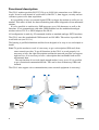
Functional description
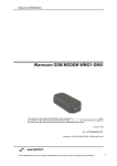
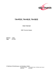
The GS-01 modem provides RS-232/V.24 up to 9 600 bit/s connections over GSM networks. It can be used instead of serial cable to link PLC’s, data loggers, security and surveillance system or for data acquisition.
It is possibility to have an external signal (DTR) to trigger the modem to call a pre-set
number. This makes it ideal for alarm monitoring and remote diagnostics from unmanned
stations.
It is also possible to send/receive SMS-messages up to 160 characters as well as fax
functions. It can communicate with other GSM-modems but also traditional analogue
modem such as TD-32 or ISDN-adapters like ID-90.
All configuration is made by AT-commands similar to standard analogue PSTN modems.
The GS-01 uses the standardised GSM network on 900 MHz. This makes it possible for
world wide use (not U.S.A.).
The housing is profiled aluminium and has been designed to be easy to use and simple to
install.
Note! To get the modem to work is it necessary to get a subscription (SIM-card) from
some network provider. To get all functions in the GS-01 to work properly it is
necessary to have the right subscription and that the network provider can support
right services. It is necessary to have a subscription that can handle both receive
and transmit data.
The test function of received signal strength makes it easy to see if it is possible
to get a functional communication link. This can be done without any SIM-card
inserted.
The GS-01 also support voice communication (some external equipment is necessary)
GS-01
GS-01
ISDN
ID-90
4
PSTN
TD-32
6195-2201
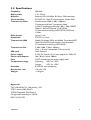
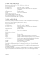
2.0 Specifications
Frequency
Radio power
Antenna
Serial interface
Transmission Data
Data format
Handshake
Transmission SMS
Transmission Fax
SIM-card
Power supply
Power consumption
Fuse
Temperature range
Humidity
Dimensions, mm
Weight
900 MHz
2 W, Class 4
External, 870 -960 MHz, 50 Ohms, SMA-connector
RS-232/V.24, 15 pin D-sub connector, female (HD)
Asynchronous 2 400, 4 800, 9 600 bit/s
Transparent and Non Transparent mode
In Non Transparent mode only: 300, 1 200, 1200/75
Mode 3.1 KHz (PSTN) and V.110 (ISDN)
AT commands according to ETSI 07.05, 07.07 and
V.25ter
Up to 11 bits
RTS/CTS or none
Mobile Originated (MO) and Mobile Terminated (MT)
Mode Text & PDU point to point. Cell broadcast
AT commands according to ETSI 07.05
2 400, 4 800, 7 200, 9 600 bit/s
Class 1, Group 3 compatible, Tele service 62
Small SIM-card
5–32V DC Option: PS-13 main adapter for 230V AC
Idle: 20 mA, active: 200mA
2.5AT mounted on the power supply cable
Operating: –20ºC to +55ºC
Storage:
–25ºC to +70ºC
0-95% RH, non-condensing
110 x 54 x 25
<140 gram
Approvals
TAC 330142-FAC33, 14th January 1999
CTR19 access GSM Phase 2
CTR20 Telephone GSM Phase 2
CE approvals according to 98-790
EMC: 89-336 CEE
6195-2201
5
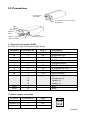
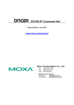
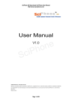
3.0 Connections
Power Supply
5-32V DC
15-pole D-sub connector, female
RS-232/V.24
LED
indication
SIM card
SIM card
holder
Antenna
SMA connector
Button to eject the
SIM card holder
3.1 Terminal connections (DCE)
RS-232/V.24, 15-pin D-sub, female, High density
Direction
O
O
I
I
–
O
I
O
O
Audio
Boot
Reset
I = Input on GS-01
Connection no.
1
6
2
8
9
7
12
11
13
4
5
10
15
3
14
CCITT
109
104
103
108.2
107
105
106
125
Description
DCD/Data Carrier Detect
RD/Receive Data
TD/Transmit Data
DTR/Data Terminal Ready
SG/Signal Ground
DSR/Data Set Ready
RTS/Request to Send
CTS/Clear to Send
RI/Ring Indicator
Microphone (+)
Microphone (–)
Speaker (+)
Speaker (–)
Boot
Reset
O = Output on GS-01
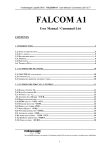
3.2 Power supply connection
Connector
4-position
Micro-Fit 3.0
6
Connection no.
1
2
3–4
Supply
+ 5 – 32V DC
0V
Not in use
1 2
3 4
6195-2201
4.0 Installation
4.1 SIM-card
To get the modem to work is it necessary to have a GSM subscription from a network
provider.
They will provide you with a SIM card that should be mounted in the SIM card holder.
Use a sharp element and press the yellow button to eject the holder. Mount the SIM card
in the holder and make sure it is correctly installed before it is pushed back into the
modem.
4.2 Antenna
Remove the protection from the SMA connector and connect the enclosed antenna.
If any other type of antenna is required it should be within the frequency 870–960 MHz,
50 Ohms.
4.3 Power supply
Use enclosed power supply cable to modem and DC power source, Red (+5–32V DC),
black (GND).
Westermo can supply a main adapter for 230V AC (Contact Westermo).
4.4 RS-232/V.24 connection
To be able to configure the modem connect the unit to a serial interface on a terminal or
PC with the enclosed serial cable. The configuration is made by using AT-commands.
It is only the RS-232/V.24 signal that is connected in enclosed cable.
4.4.1 Voice/Audio
To be able to use Voice/audio facility another serial cable has to be used
(Contact Westermo).
4.4.2 Boot/Reset
To be able to use Boot/Reset facility another serial cable has to be used
(Contact Westermo).
6195-2201
7
5.0 Configuration
Note! To be able to configure the modem all the AT-commands has to be written with
capital letters, e.g. AT+CPIN.
In this manual we have only described the most frequently used commands. For the complete AT-commands manual, please, visit our web, www.westermo.se where you can find it
in PDF-format.
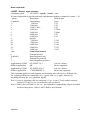
General commands
+CGMM – Request model identification
This command is used to get the supported bands (GSM 900, DCS 1800 or PCS 1900).
The answer could be a combination of different bands in the case of multiband modules.
Application to GSM
GSM to application
AT+CGMM
900P
OK
get hardware version
GSM 900 MHZ primary band, or
“900E” (extended band), “1800” (DCS),
“1900” (PCS) or “MULTIBAND”
+GCAP – Capabilities list
This command gives the complete capabilities list.
Application to GSM
GSM to application
AT+GCAP
+GCAP: +CGSM +FCLASS
get capabilities list
supports GSM commands
and FAX
A/ – Repeat last command
Only A/ command can not be repeated.
This command repeats the last command executed.
Application to GSM
8
A/
repeat last command
6195-2201
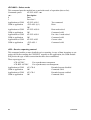
Call control commands
D – Dial command
Command syntax:
ATD <Numb> [I / i] [G/g] [;]
ATD> <PhbStr> [I / i] [G/g] [;]
ATD> mem <n> [I / i] [G/g] [;]
ATD> <PhbIndex> [I / i] [G/g] [;]
The ATD command is used to establish a speech, data or fax call.
For a data or fax call, the application sends to the GSM module the following ASCII
string: (the bearer has to be selected before with the +CBST command)
ATD<nb>
where <nb> is the called phone number.
For a voice call, the application sends to the GSM module the following ASCII string:
(the bearer has to be selected before, if not a default bearer is used)
ATD<nb>;
where <nb> is the called phone number.
Please, notice that in case of international number, the local international prefix has not
to be set (usually 00) but need to be replaced by the ”+” character.
Example: to establish a voice call to Wavecom from another country,
the AT command shall be:
ATD+33146290800;
Notice that some countries can have particular numbering rules for their GSM handset
numbering.
The answer to the ATD command can be one of the following ones:
Verbose result code
Numeric (V0 set)
Description
OK
0
if the calls succeeds, for voice
call only
CONNECT <speed>
10,11,12,13,14,15
if the calls succeeds, for data calls
only, <speed> takes the value
negotiated by the GSM module
BUSY
7
if the called party is already in
communication
NO ANSWER
8
if no hang up is detected
after a fixed network time-out
NO CARRIER
3
Call setup failed or remote user
release. Use the AT+CEER
command to know the failure
cause
6195-2201
9
Direct dialling from a phonebook location (stored in SIM card) can be done with the
following command:
ATD> <index>; for calling <index> from the selected phonebook
(by +CPBS command)
ATD>”BILL”; for calling ”BILL” from the selected phonebook
ATD> mem <index> (mem is ”SM”, ”FD” or ”ON”, see +CPBS command)
is a way to directly dial from a phonebook number.
Application to GSM
GSM to application
AT+CPBS?
+CPBS:”FD”,
5,10
Application to GSM
ATD>SM6;
Which phonebook is selected?
FDN phonebook is selected
5 locations are used and 10
locations are available.
Call index 6 from ADN phonebook
When FDN phonebook has been locked only the numbers beginning with the digits of
FDN phonebook entries can be called.
For example, if ”014629” is written in the FDN phonebook all the phone numbers
beginning with these 6 digits can be called.
It is allowed to override the CLIR supplementary service subscription for this call only.
”I” means “invocation” (restrict CLI presentation)
”i” means “suppression” (allow CLI presentation).
It is allowed to control the CUG supplementary service information by ”G” or ”g” for
this call only. The index and info values set with command +CCUG are used. An outgoing call attempt could be refused if the AOC service is active and the credit is expired
(NO CARRIER).
When trying to make an outgoing call while there is an active call, the active call is first
put on hold, then the call setup is made.
10
6195-2201
H – Hang-Up command
The command ATH (or ATH0) is used by the application to disconnect the remote user.
In case of multiple calls, all calls are released (active, held and waiting calls).
The specific Wavecom command ATH1 has been appended to disconnect only the outgoing call. It can be useful in case of multi communication.
Application to GSM
GSM to application
Application to GSM
GSM to application
ATH
OK
ATH1
OK
ask for disconnection
all calls, if any, are released
ask for outgoing call disconnection
outgoing call, if any, is released
A – Answer a call
When the GSM module receives a call, it set the RingInd signal and sends to the application the ASCII string ”RING” or ”+CRING: <type>” if cellular result code (+CRC) is
enabled. Then it waits for the application to accept the call.
GSM to application
Application to GSM
GSM to application
Application to GSM
GSM to application
RING
ATA
OK
ATH
NO CARRIER
incoming call
answer to this incoming call
call accepted
disconnect call
call disconnected
ATDL – Redial last number
This command is used by the application to redial the last number used in the ATD
command. The last dialled number is displayed followed by ”;” for speech calls only.
Application to GSM
GSM to application
6195-2201
ATDL
0146290800;
OK
redial last number
last call was a speech call
command valid
11
AT%Dn – Automatic dialling with DTR
This command allows to activate and deactivate automatic dialling of the phone number
stored in the first location of ADN phonebook. The number is dialled on DTR OFF to ON
transition.
Sets commands:
Options:
;
AT%D0
AT%D1;
AT%D1
Example:
Application to GSM
GSM to application
AT%D<n>[;]
n (0–1)
for activate or deactivate the automatic
dialling.
Informs the module that the number is a
voice rather than a fax or data number.
Deactivates automatic DTR dialling.
Activates automatic DTR dialling if
DTR switches from OFF to ON;
Dials the phone number in the first
location of ADN phonebook.
Speech call
Activates automatic DTR dialling if
DTR switches from OFF to ON;
Dials the phone number in the first
location of ADN phonebook.
Data or Fax call.
AT%D1;
OK
DTR is OFF
DTR switches ON
DTR switches OFF
12
Activates DTR dialling.
Command has been executed.
The number in the first location
of the ADN phonebook is dialled
automatically.
The module goes on-hook.
6195-2201
ATS0 – Automatic answer
This S0-parameter controls the automatic answering feature of the mobile.
Application to GSM
GSM to application
Application to GSM
GSM to application
ATS0=2
Automatic answer after 2 rings
OK
ATS0?
Current value
002
Always 3 characters with leading
OK
zeros
Application to GSM
ATS0=0
No automatic answer
GSM to application
OK
Command valid
All others S-parameters (S6,S7,S8 ...) are not implemented.
+CICB – Incoming Call Bearer
Command syntax:
AT+CICB= <mode>
This specific command is used for incoming call type when no incoming bearer is given
(single numbering scheme, see +CSNS).
<mode> values:
0: Data
1: Fax
2: Speech
Application to GSM
AT+CICB=1
GSM to Application
Application to GSM
OK
AT+CICB=2
GSM to Application
Application to GSM
OK
AT+CICB?
GSM to Application
+CICB: 2
Application to GSM
GSM to Application
AT+CICB=?
+CICB: (0-2)
6195-2201
If no incoming bearer, force a fax
call
Command accepted
If no incoming bearer, force a
speech call
Command accepted
Interrogate value
Default incoming bearer:
speech call
Test command
Speech, data or fax default
incoming bearer
13
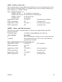
Network service commands
+CSQ – Signal Quality
This command shall be used to know the received signal strength indication (<rssi>) and
the channel bit error rate (<ber>) with or without any SIM card inserted.
<rssi>:
0: –113 dBm or less
1: –111 dBm
2...30: –109 to –53 dBm
31: –51dBm or greater
99: not known or not detectable
<ber>:
0...7: as RXQUAL values in the table GSM 05.08
99: not known or not detectable
Application to GSM
AT+CSQ
GSM to application
+CSQ: <rssi>,<ber>
<rssi> and <ber> as defined
OK
before
+CREG – Network registration
This command is used by the application to know the registration status of the mobile.
Command syntax:
Response syntax:
AT+CREG= <mode>
+CREG: <mode>, <stat> [ ,<lac>,<ci> ]
for AT+CREG? command only
<mode>
0: Disable network registration unsolicited result code (default)
1: Enable network registration code result code +CREG: <stat>
2: Enable network registration and location information unsolicited
result code +CREG: <stat>,<lac>,<ci> if there is a change of the network cell.
<stat>
0: not registered, ME is not currently searching a new operator
1: registered, home network
2: not registered, ME currently searching a new operator to register to
3: registration denied
4: unknown
5: registered, roaming
<lac>: string type; two byte location area code in hexadecimal format
(e.g. ”00C3” equals 193 in decimal)
<ci>: string type; two byte cell ID in hexadecimal format
Application to GSM
AT+CREG?
GSM to application
+CREG: <mode>,<stat> as defined before
OK
14
6195-2201
Application to GSM
AT+CREG=<mode>
GSM to application
Application to GSM
GSM to application
OK
AT+CREG=?
+CREG: (0–2)
Disable/enable network
registration
Unsolicited result code
Command valid
0,1,2 <mode> values
are supported
Security commands
+CPIN – Enter PIN
This command is used to enter ME passwords (CHV1 / CHV2 / PUK1 /PUK2…) which
are needed before any other functionality of the ME can be used. The CHV1/CHV2
length is between 4 and 8 digits, the PUK1/PUK2 length is 8 digits only.
If the user application try to establish an outgoing call before having validated the
SIM PIN code (CHV1), then the GSM module will refuse the ”ATD” command with a
”+CME ERROR: 11” (SIM PIN required).
It’s up to the application to validate the PIN after each reset or power on if the PIN was
enabled.
The application shall therefore use the command:
AT+CPIN=<pin>
Application to GSM
GSM to application
Application to GSM
GSM to application
AT+CPIN=1234
OK
AT+CPIN=5678
+CME ERROR: 3
Enter PIN
PIN code is correct
enter PIN
Operation not allowed,
PIN previously entered
After 3 unsuccessful codes, the PUK will then be required. The PUK validation forces
the user to enter as a second parameter a new PIN code which will be the new PIN code
if the PUK validation succeeds. The CHV1 is then enabled if the PUK1 is correct.
The application shall therefore use the command:
AT+CPIN=<Puk>,<NewPin>
Application to GSM
AT+CPIN=00000000,1234
GSM to application
+CME ERROR: 16
Application to GSM
AT+CPIN=12345678,1234
GSM to application
6195-2201
OK
Enter PUK and new PIN
Incorrect PUK
Enter PUK and new PIN,
2nd attempt
PUK correct, new PIN
stored
15
To know which code has to be entered (or not), the following interrogation command can
be used:
AT+CPIN?
The possible responses are:
+CPIN: READY
ME is not pending for any password
+CPIN: SIM PIN
CHV1 is required
+CPIN: SIM PUK
PUK1 is required
+CPIN: SIM PIN2
CHV2 is required
+CPIN: SIM PUK2
PUK2 is required
+CPIN: PH-SIM PIN
SIM lock (phone-to-SIM) is required
+CPIN: PH-NET PIN
Network personnalisation is required
+CME ERROR: <err>
SIM failure (13) absent (10) etc...
Please note that in this case the mobile does not finish its response with the OK string.
The response +CME ERROR: 13 (SIM failure) is returned after 10 unsuccessful PUK
presentations. The SIM card is then out of order and shall be replaced by a new one.
Example: 3 failed PIN validations + 1 successful PUK validation
AT+CPIN?
Read the PIN status
+CPIN: SIM PIN
The GSM module requires SIM PIN
AT+CPIN=1235
First attempt to enter a SIM PIN
+CME ERROR: 16
Bad PIN
AT+CPIN=1236
Second attempt
+CME ERROR: 16
Bad PIN
AT+CPIN=1237
Third attempt
+CME ERROR: 16
Bad PIN
AT+CPIN?
Read PIN state
+CPIN: SIM PUK
The GSM module requires PUK
AT+CPIN=99999999,5678
The PUK is entered, the new PIN shall be
OK
5678 PUK validation is OK. New Pin is 5678
AT+CPIN?
Read PIN state
+CPIN: READY
GSM module is ready
If the user try to do something which requires PIN2 (CHV2) the GSM module will refuse
his action with a ”+CME ERROR: 17” (SIM PIN2 required).
Then the GSM module is waiting SIM PIN2 to be given.
16
6195-2201
Of course if SIM PIN2 is blocked, SIM PUK2 is required instead of SIM PIN2.
For instance, the GSM module needs PIN2 to write in the fixed dialling phonebook
(FDN), so if SIM PIN2 authentification has not been done during the current cession the
SIM PIN2 is required:
Application to GSM
GSM to application
Application to GSM
AT+CPBS=”FD”
OK
AT+CPBW=5,”01290917”,129,”Jacky”
GSM to application
+CME ERROR:17
Application to GSM
GSM to application
AT+CPIN?
SIM PIN2
Application to GSM
GSM to application
Application to GSM
AT+CPIN=5678
OK
AT+CPBW=5,”01290917”,129,”Jacky”
Choose FDN
Write in FDN at
location 5
SIM PIN2 is
required
SIM PIN2 is
required
Enter SIM PIN2
Write in FDN at
location 5
GSM to application
OK
Now writing in
FDN is allowed
Please note that the GSM module ask only once PIN2 or PUK2, so if they aren’t entered
right, the next +CPIN? command will return ”+CPIN: READY”.
Remark
In the way Application to GSM, an ”h” character shall be added before the PIN value if
cyphering mode (with D.E.S algorithm) is on. See +EXPKEY command.
Same remark for +CLCK and +CPWD commands.
6195-2201
17
+CLCK – Facility lock
This command shall be used by the application to lock, unlock or interrogate a ME
or network facility <fac>.
Command syntax: AT+CLCK= <fac>,<mode>[,<passwd>[,<class>] ]
Response syntax: +CLCK: <status> [ ,<class1> ]
<CR><LF>+CLCK: <status>,<class2>
[…]]
Command
Possible responses
AT+CLCK=”SC”,1,1234
OK
Note: Enable PIN
Note: PIN was right
AT+CLCK?
+CLCK: (”PS”, 0), (”PN,0),(”FD”,0)
Note: Read PIN status
OK
Note: PIN is enables, no SIM lock, no network lock, no
informati_n on Call barring
(no longer supported in GSM 07.07)
AT+CLCK=”SC”,0,5555
+CME ERROR: 16
Note: Disable PIN
Note: PIN was wrong
AT+CPIN=1234
OK
Note: Enter PIN
Note: PIN was good
AT+CLCK=?
+CLCK:(”PS”,”SC”,”AO”,”OI”,”OX”,”AI”,”IR”,”AB”,
Note: Request supported
OK
facilities
Note: Supported facilities
AT+CLCK=”PN”,1,12345678 OK
Note: Activate network lock
Network lock activated
AR+CLCK=”AO”,1,1234,2
OK
Note: Activate all outgoing
Note: Call barring is activate
calls barring for data calls
AT+CLCK=”AO”,2
<CR><LF> +CLCK: 1,2
Note: Query BAOC status
OK
Note: BAOC activate for data calls only
18
6195-2201
Defined values
The following <fac> values are supported:
”PS”:
”SC”:
”AO”:
”OI”:
”OX”:
”AI”:
”IR”:
”AB”:
”AG”:
”AC”:
”PN”:
”FD”:
SIM lock facility with a 8 digits password.
PIN enable (<mode> = 1) / disable (<mode> = 0)
BAOC (Barr All Outgoing Calls)
BOIC (Barr Outgoing International Calls)
BOIC-exHC (Barr Outg. Internat Calls except to Home Country)
BAIC (Barr All Incoming Calls)
BIC-Roam (Barr Inc. when Roaming outside Home Country)
All Barring services
All outGoing barring services
All inComing barring services
Network lock with a 8 digits password (NCK).
SIM Fixed Dialling Numbers (FDN) memory feature
(PIN2 is required as <password>)
<mode> 0: unlock the facility
1: lock the facility
2: query status
<class>: A facility status can be changed for only one class, or for all classes
(7 or omitted).
<class> 1: Voice (telephony)
2: Data (refer to all bearer services)
4: Fax (facsimile services)
8: Short Message service
7: equal to all classes (Default value)
Any attempt to combine different classes will result in activation/desactivation/
interrogation of all classes.
The password maximum length is given with the AT+CPWD=? command.
6195-2201
19
Supplementary Services commands
+CLCK – Call barring
This command allows control of the call barring supplementary service.
Locking, unlocking or querying the status of a call barring is possible for
all or a specific class.
Command Syntax:
AT+CLCK= <fac>, <mode> [, <password> [, <class> ] ]
Response Syntax:
(for <mode>=2 and command successful)
+CLCK: <status> [, <class1> [<CR><LF>+CLCK: <status>, <class2>, [...] ]
* <fac>:
”AO”, ”OI”, ”OX”
for outgoing calls barring
”AI”, ”IR”
for incoming calls barring
”AG”, ”AC”, ”AB”
for all calls barring (<mode>=0 only)
* <mode>
0
unlocks the facility
1
locks the facility
2
query status
* <class>:see description for +CLCK command (Call Barring)
The combination of different classes in not supported, it will only result in the activation
/ deactivation / status request of all classes (7).
Password code must be on 4 digits maximum.
Application to GSM
AT+CLCK=”AO”,1,1234
GSM to application
OK
Command valid
Application to GSM
AT+CLCK=”AO”,0,5555
GSM to application
+CME ERROR: 16
Wrong password
Application to GSM
AT+CLCK=”AO”,0,1234
GSM to application
OK
Command valid
+CPWD – Modify SS password
This command shall be used by the application to change the supplementary service password. The command to manage this functionality is:
Command Syntax:
AT+CPWD=<fac>,<OldPassword>, <NewPassword>
for <fac> see +CLCK command with only ”P2” facility added (SIM PIN2).
Application to GSM
AT+CPWD=”AO”,1234,5555
Change Call Barring
password
20
6195-2201
GSM to application
OK
Password changed
Application to GSM
AT+CPWD=”AO”,1234,5555
Change password
GSM to application
+CME ERROR: 16
Wrong password
Application to GSM
AT+CPWD=”AO”,5555,1234
Change password
GSM to application
OK
Password changed
Whatever the facility, the change of password is performed for all calls barring.
+CLIP – Calling line identification presentation
This command allows control of the calling line identification presentation supplementary
service. When the presentation of the CLI (Calling Line Identification) is enabled (and
calling subscriber allows), +CLIP response is returned after every RING (or +CRING)
result code.
Command syntax:
AT+CLIP=<n>
Response syntax:
+CLIP: <n>,<m>
for AT+CLIP?
+CLIP: <number>, <type>[,<subaddr>, <satype>, <alpha>]
for an incoming call, after each RING or +CRING indication
<n>: parameter sets/shows the result code presentation in the TA
0
Disable
1
Enable
<m>: parameter shows the subscriber CLIP service status in the network
0
CLIP not provisioned
1
CLIP provisioned
2
Unknown (no network...)
Application to GSM
AT+CLIP=1
Enable CLIP
GSM to application
OK
CLIP is enabled
Application to GSM
AT+CLIP?
Ask for current functionality
GSM to application
+CLIP: <n>,<m>
<n> and <m> defined as above
OK
GSM to application
RING
Incoming call
+CLIP:
Incoming call with number and
“070888888”129,1,,,
name presentation
“FRED”
Application to GSM
AT+CLIP=0
Disable CLIP presentation
GSM to application
OK
Command valid
6195-2201
21
Phonebook commands
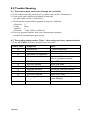
+CPBS – Select phonebook memory storage
This command selects phonebook memory storage. The available phonebooks are
the ADN (SIM), FDN (SIM fixdialling, restricted phonebook), and MSISDN
(SIM own numbers) phonebooks.
Application to GSM
GSM to application
Application to GSM
GSM to application
OK
Application to GSM
GSM to application
AT+CPBS= ”SM”
OK
AT+CPBS=?
+CPBS: (”SM”,”FD”,”ON”)
Select ADN phonebook
ADN phonebook is selected
Possible values
ADN, FDN, MSISDN
Phonebooks supported
AT+CPBS?
Status
+CPBS: ”SM”,10,20
ADN phonebook selected,
OK
10 used locations, 20 locations
available
The ADN phonebook could not be selected is FDN is active.
+CPBR – Read phonebook entries
This command returns phonebook entries for a location range from the current phonebook
memory storage selected with +CPBS.
Application to GSM
GSM to application
AT+CPBR=?
+CPBR: (1-50), 20,10
OK
Application to GSM
GSM to application
AT+CPBR=12,14
+CPBR: 12,”112”,129,
”Emergency” +CPBR: 13,
”+331290909”,145, ”Fred”
+CPBR: 14, ”0146290808”,
129, ”Zazi”
OK
AT+CPBR=10
+CPBR:10,”0146290921”,
129,”Rob”
OK
AT+CPBR=52
+CME ERROR: 21
Application to GSM
GSM to application
Application to GSM
GSM to application
22
Test command
50 locations (from 1 to 50),
max length of 20 for phone
10 characters max for the
associated text
Read entries from 12 to 14
Display locations 12,13,14
with Location, Number,
Type (TON/NPI), Text
Read entry 10
Display location 10
Read entry 52 (wrong)
Invalid index
6195-2201
+CPBF – Find phonebook entries
This command returns phonebook entries which alphanumeric field start with a given
string. The AT+CPBF= ”” command can be used to display all phonebook entries sorted
in alphabetical order.
Application to GSM
GSM to application
Application to GSM
GSM to application
Application to GSM
GSM to application
AT+CPBF=?
+CPBF: 20,10
OK
AT+CPBF= ”E”
+CPBF: 12,”112”,129,
”Emergency”
+CPBF: 15,”+331290101”,
145, ”Eric”
OK
AT+CPBF=”H”
+CME ERROR: 22
Test command
Max length of 20 for phone
10 characters for the text
Read entries with ”E”
Display locations with text
field starting with ”E”
Read entries with ”H”
Entry not found
+CPBW – Write phonebook entry
This command writes phonebook entry in location number <index> in the current phonebook memory storage.
Application to GSM
GSM to application
Application to GSM
GSM to application
Application to GSM
GSM to application
Application to GSM
GSM to application
Application to GSM
GSM to application
6195-2201
AT+CPBW=?
+CPBW: (1-50),20,
(129,145),10
OK
AT+CPBW=3
OK
AT+CPBW=5,
”112”,129 ,”SOS”
OK
AT+CPBW=5,”01290917”,
129,”Jacky”
OK
AT+CPBW=,
”+33145221100”,145,
”SOS”
OK
Test command
50 locations, phone length=20,
TON/NPI of 129 or 145, text
length=10
Erase location 3
Location 3 erased
Write at location 5
Location 5 written
Overwrite location 5
Location 5 is overwritten
Write at the first free location
Free location is written
23
Application to GSM
GSM to application
Application to GSM
GSM to application
Application to GSM
GSM to application
Application to GSM
GSM to application
AT+CPBW=,”0345221100”,
129,”SOS”
+CME ERROR: 20
AT+CPBW=57,”112”,
129 ,”WM”
+CME ERROR: 21
AT+CPBW=7,
”012345678901234567
890”,129 ,”WAVE”
+CME ERROR: 26
AT+CPBW=7,
”0122334455”,129 ,
”WAVECOM TEL”
+CME ERROR: 24
Write at the first free location
Phonebook full
Write at loc 57 (wrong)
Invalid index
Write at loc. 7 a long Phone
number (21 digits)
Phone too long
Write at loc. 7 a long Text
(11 characters)
Text too long
When the fixed dialling phonebook (FDN) is locked , this command is not allowed.
Moreover, when FDN is unlocked, PIN2 is required to write in the FDN phonebook.
But if PIN2 authentification has been done during the current cession ,
+CPBW command with FDN is allowed .
Application to GSM
GSM to application
Application to GSM
GSM to application
Application to GSM
GSM to application
Application to GSM
GSM to application
Application to GSM
GSM to application
24
AT+CPBS=”FD”
OK
AT+CPBW=5,”01290917”,
129,”Jacky”
+CME ERROR:17
AT+CPIN?
SIM PIN2
AT+CPIN=5678
OK
AT+CPBW=5,”01290917”,
129,”Jacky”
OK
Choose FDN
Write in FDN at location 5
SIM PIN2 is required
SIM PIN2 is required
Enter SIM PIN2
Write in FDN at location 5
Now writing in FDN is allowed
6195-2201
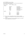
Data commands
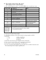
+CBST – Bearer type selection
Command syntax:
AT+CBST= <speed>, <name>, <ce>
No data compression is provided and only asynchronous modem is supported (<name> = 0).
<speed>
Description
Modem type
0 (default)
Autobauding
None
1
300 bit/s
V.21
2
1 200 bit/s
V.22
3
1 200/75 bit/s
V.23
4
2 400 bit/s
V.22bis
5
2 400 bit/s
V.26ter
6
4 800 bit/s
V.32
7
9 600 bit/s
V.32
8
Specific
65
300 bit/s
V.110
66
1 200 bit/s
V.110
68
2 400 bit/s
V.110
70
4 800 bit/s
V.110
71
9 600 bit/s
V.110
<ce>
Connection element
0
Transparent only
1(default)
Non transparent only
2
Transparent preferred
3
Non transparent preferred
Application to GSM
AT+CBST=7,0,1
Ask for a bearer
GSM to application
OK
Bearer supported
Application to GSM
AT+CBST=81,0,0
Ask for a bearer
GSM to application
+CME ERROR: 4
Bearer not supported
This command applies to both outgoing and incoming data calls but in a different way.
For outgoing call the two parameters (e.g. <speed> and <ce>) apply, whereas for
incoming call only the <ce> parameter applies.
Note 1) as far as incoming calls are concerned, if <ce> is set to T only and the network
proposes NT only or vice versa then the call is released.
Note 2) older values 100 and 101 for <ce> are retained for compatibility purpose but shall
not be used anymore, values 2 and 3 shall be used instead.
6195-2201
25
+FCLASS – Select mode
This command puts the module into a particular mode of operation (data or fax).
Command syntax:
AT+FCLASS= <n>
<n>
Description
0
Data
1
Fax class 1
Application to GSM
AT+FCLASS=?
Test command
GSM to application
+FCLASS: (0,1)
Done
OK
Application to GSM
AT+FCLASS=0
Data mode asked
GSM to application
OK
Command valid
Application to GSM
AT+FCLASS=1
Fax class 1 mode asked
GSM to application
OK
Command valid
Application to GSM
AT+FCLASS?
Current value
GSM to application
+FCLASS: 1
Command valid
OK
+CR – Service reporting control
This command enables a more detailed service reporting, in case of data incoming or outgoing call. Before sending the CONNECT response to the application, the GSM module
will precise the type of data connection that have been established.
These report types are:
+CR: ASYNC
For asynchronous transparent
+CR: REL ASYNC
For asynchronous non-transparent
Application to GSM
AT+CR=0
Extended reports disabled
GSM to application
OK
Command valid
Application to GSM
AT+CR=1
Extended reports enabled
GSM to application
OK
Command valid
26
6195-2201
+CRC – Cellular result codes
This command enables a more detailed ring indication, in case of incoming call (voice or
data). Instead of the string ”RING”, an extended string is used to indicate which type of
call is ringing (e.g. +CRING: VOICE).
These extended indications are:
+CRING: ASYNC
for asynchronous transparent
+CRING: REL ASYNC for asynchronous non-transparent
+CRING: VOICE
for normal speech.
+CRING: FAX
for fax calls
Application to GSM
AT+CRC=0
Extended reports disabled
GSM to application
OK
Command valid
Application to GSM
AT+CRC=1
Extended reports enabled
GSM to application
OK
Command valid
+DOPT – Other radio link parameters
This Wavecom specific command allows to change some supplementary radio link
protocol parameters.
Command syntax:
AT+DOPT=<reset_allowed>,<dtx_allowed>
<reset_allowed>
Description
0
Data communication is hung up in case of bad radio link.
1 (default)
Data communication goes on in case of bad radio link
(possible loose of data)
The second parameter is reserved for future use.
Application to GSM
AT+DOPT=?
Test command
GSM to application
(0,1),(0,1)
OK
Application to GSM
AT+DOPT=1
Set new parameters
GSM to application
OK
Command valid
Application to GSM
AT+DOPT?
Current values
GSM to application
1,1
Command valid
OK
6195-2201
27
V24-V25 commands
+IPR – Fixed DTE rate
This commands specifies the data rate at which the DCE will accept commands.
Application to GSM
AT+IPR?
GSM to application
+IPR: 9 600
current rate is 9 600 bit/s
OK
Application to GSM
AT+IPR=?
GSM to application
+IPR:(0, 2 400, 4 800, 9 600, 19 200) , possible values (1)
(300, 600, 1 200, 38 400, 57 600, 115 200)
OK
Application to GSM
AT+IPR=38 400
GSM to application
OK
disable autobauding and set rate to
38 400 bit/s
Application to GSM
AT+IPR=0
GSM to application
OK
enable autobauding
Note (1): first set of values indicates the range of auto detectable speeds. The second set
of values indicates all the possible speeds which can be used by DCE.
An autobauding is provided which operates from 2 400 to 19 200 baud.
However some constraints have to be dealt with:
Any AT command issued by DTE must start with a capital ‘A’ and ‘T’ (or ‘\’). If not, DCE
may send back some garbagge characters and get de-synchronized. Should it happen,
DTE shall just issue once or twice ‘AT\r’ (at 2 400 or 4 800 baud) or just ‘AT’
(at 9 600 baud) to get the modem re-synchronized.
The DTE shall wait for 1ms after receipt of the last character of the AT response
(which is always ‘\n’ or 0x0A) to send a new AT command at either the same rate or a
new rate. Shoud this delay ignored, DCE can get de-synchronised. Once again, sending
once or twice ‘AT\r’ or just ‘AT’ causes the DCE to recover.
Be careful: at start-up if autobauding is enabled and no AT command has been received
yet, the module sends all unsolicited responses (like RING) at 9 600 baud.
28
6195-2201
+ICF – DTE-DCE character framing
This command is used to determine the local serial port start-stop (asynchronous)
character framing that the DCE shall use.
Command syntax:
* <format>:
0
1
2
3
4
5
6
* <parity>:
0
1
2
3
4
AT+ICF= <format>, <parity>
Autodetect
8 Data 2
8 Data 1
8 Data 1
7 Data 2
7 Data 1
7 Data 1
Not supported
Stop supported
Parity 1 Stop supported
Stop supported
Stop supported
Parity 1 Stop supported
Stop supported
Odd
Even
Mark
Space
None
Supported
Supported
Supported
Supported
Supported
Note 1) Setting a character framing different from 8N1 will disable autobauding
(in the case it was activated). However setting it back to 8N1 will not re-enable
autobaud.
Note 2) Setting the framing to 8N1 will let the autobauding enabled, if it was already
enabled (implying framing was already 8N1).
6195-2201
29
+IFC – DTE-DCE local flow control
This command is used to control the operation of local flow control between the DTE
and DCE.
AT+IFC=<DCE_by_DTE>,<DTE_by_DCE>
* < DCE_by_DTE >:
0
1
2
3
none
Xon/Xoff local circuit 103
RTS
Xon/Xoff global on circuit 103
Supported
Not supported
Supported
Not supported
Important note: When this parameter is set to 2 (DTE invokes flow control through RTS)
the behavior of the DCE is the following:
If the DCE has never detected RTS in high (or ON) condition since
startup then it ignores RTS, assuming this signal is not connected.
As soon as DCE detects RTS high, then this signal acts upon it.
Therefore subsequent RTS transition to OFF will prevent DCE from
sending any further data in online and in offline as well.
This behavior allows the user to use the default settings (hardware flow
control) and let RTS disconnected. In the case RTS is connected and is
high at least once then it acts upon DCE.
< DTE_by_DCE >:
0
none
Supported
1
Xon/Xoff circuit 104
Not supported
2
CTS
Supported
When this parameter is set to 0 (none) then CTS is kept high all the time.
Application to GSM
AT+IFC?
GSM to application
+IFC: 2,2
Current values
OK
Application to GSM
AT+IFC=?
GSM to application
+IFC: (0,2),(0,2)
Possible values
OK
Application to GSM
AT+IFC=0,0
GSM to application
OK
New values
30
6195-2201
&C – Set DCD signal
This commands controls the Data Carrier Detect (DCD) signal.
Application to GSM
GSM to application
Application to GSM
AT&C0
OK
AT&C1
GSM to application
OK
DCD always on
Command valid
DCD matches state of the remote
modem’s data carrier
Command valid
&D – Set DTR signal
This commands controls the Data Terminal Ready (DTR) signal.
Application to GSM
GSM to application
Application to GSM
AT&D0 the
OK
AT&D1
GSM to application
Application to GSM
OK
AT&D2
GSM to application
OK
DTR signal is ignored
Command valid
Modem switches from data to
command mode when DTR
switches from ON to OFF
Command valid
Upon DTR switch from ON to
OFF, the call is clear down
Command valid
&S – Set DSR signal
This commands controls the Data Set Ready (DSR) signal.
Application to GSM
GSM to application
Application to GSM
AT&S0 DSR
OK
AT&S1
GSM to application
OK
Always on
Command valid
DSR off in command mode,
DSR on in data mode
Command valid
O – Back to online mode
If you have established a connection and the mobile is in online command mode, this
command allows to return to online data mode.
Application to GSM
GSM to application
6195-2201
ATO
OK
Command valid
31
Q – Result code suppression
Determines whether the mobile sends result codes or not.
Application to GSM
GSM to application
Application to GSM
ATQ0
OK
ATQ1
GSM to application
(none)
DCE transmits result codes
Command valid
Result codes are suppressed and
not transmitted
No response
V – DCE response format
Determines the DCE response format, with or without header characters
<CR><LF>, and with the use of numeric result codes.
Information
responses
Result codes
V0
<text><CR><LF>
<numeric code><CR>
Application to GSM
ATV0
GSM to application
Application to GSM
0
ATV1
GSM to application
OK
V1
<CR><LF>
<text><CR><LF>
<CR><LF>
<verbose code><CR><LF>
DCE transmits limited headers
and trailers and numeric result
codes
Command is valid (0 means OK)
DCE transmits full headers and
trailers and verbose response text
Command is valid
Z – Default configuration
Restores the configuration profile. Any call is released.
Application to GSM
GSM to application
ATZ
OK
Command valid
&W – Save configuration
This commands writes the active configuration to a non-volatile memory (EEPROM).
Application to GSM
AT&W
GSM to application
OK
32
Writes current configuration
to EEPROM
Command valid
6195-2201
E – Echo
This command is used to determines whether or not the modem echoes characters received by an external application (DTE).
Application to GSM
GSM to application
Application to GSM
GSM to application
ATE0
OK
ATE1
OK
Characters are not echoed
Done
Characters are echoed
Done
&F – Restore factory settings
This command is used to restore the factory settings from EEPROM.
Application to GSM
AT&F
GSM to application
Application to GSM
OK
AT&F0
GSM to application
OK
Ask for restoring the factory
settings
Done
Ask for restoring the factory
settings
Done
&V – Display configuration
This command is used to display modem configuration.
&V0:
Display the modem configuration in RAM.
&V1:
Display the modem configuration in EEPROM.
&V2:
Display the factory modem configuration.
The parameters which are displayed are the following:
Q, V, S0, S2, S3, S4, S5, +CR, +CRC, +CMEE, +CBST, +SPEAKER, +ECHO
Application to GSM
GSM to application
6195-2201
AT&V0
RAM modem parameters
Q:0 V:1 S0:000 S2:043 Done
S3:013 S4:010 S5:008
+CR:0 +CRC:0
+CMEE:0 +CBST:0,0,1
+SPEAKER:0 +ECHO:0
OK
33
I – Request identification information
This command causes the GSM module to transmit one or more lines of specific
information text.
Display the manufacturer followed by model identifications.
This command is equivalent to +CGMI and +CGMM.
I3:
Display the revision identification (equivalent to +CGMR).
I4:
Display the modem configuration in RAM (equivalent to &V0).
I5:
Display the modem configuration in EEPROM (equivalent to &V1).
I6:
Display the modem data features. This command enumerates the supported data rates, data modes, and fax classes.
I7:
Display the modem voice features.
If the value is different, an ”OK” string will be sent back.
I0:
Application to GSM
ATI0
GSM to application
WAVECOM MODEM
900P
OK
ATI3
Application to GSM
GSM to application
Application to GSM
GSM to application
Application to GSM
34
310_G250.51 806216
032199 17:04
OK
ATI6
DATA RATES:
AUTOBAUD, 300, 1 200,
1 200/75, 2 400, 4 800, 9 600
DATA MODES:
T/NT, ASYNCHRONOUS
FAX CLASS 1
OK
ATI7
Manufacturer and model
identifications
GSM 900 MHz
primary band
Revision identification
Software release 3.10,
revision 51 generated on
the 21st of March 1999
Modem data features
Done
Modem voice features
6195-2201
Short Message commands
Parameters definition
<da>
<dcs>
<dt>
<sn>
<st>
<stat>
<tooa>
<tora>
<tosca>
<total1>
<total2>
<used1>
<used2>
<vp>
Destination Address, coded like GSM 03.40 TP-DA.
Data Coding Scheme, coded like in document [5].
Discharge Time in string format: ”yy/MM/dd,hh:mm:ss±zz”
(Year [00-99], Month [01–12], Day [01–31], Hour, Minute,
Second and Time Zone [quarters of an hour]).
First Octet, coded like SMS-SUBMIT first octet in
document [4], default value is 17 for SMS-SUBMIT.
Place of storage in memory.
Text mode (+CMGF=1): number of characters PDU mode
(+CMGF=0): length of the TP data unit in octets.
Memory used to list, read and delete messages.
(+CMGL, +CMGR and +CMGD).
Memory used to write and send messages.
(+CMGW, +CMSS).
CBM Message Identifier.
Message Reference.
Originator Address.
Protocol Identifier.
For SMS: GSM 04.11 SC address followed by GSM 03.40
TPDU in hexadecimal format, coded as specified in doc [4]
For CBS: GSM 03.41 TPDU in hexadecimal format.
Recipient Address.
Service Center Address.
Service Center Time Stamp in string format:
“yy/MM/dd,hh:mm:ss±zz”.
(Year/Month/Day,Hour:Min:Seconds±TimeZone).
CBM Serial Number.
Status of a SMS-STATUS-REPORT.
status of message in memory.
Type-of-Address of <oa>.
Type-of-Address of <ra>.
Type-of-Address of <sca>.
Number of message locations in <mem1>.
Number of messages locations in <mem2.
Total number of messages locations in <mem1>.
Total number of messages locations in <mem2.
Validity Period of the short message, default value is 167.
6195-2201
35
<fo>
<index>
<length>
<mem1>
<mem2>
<mid>
<mr>
<oa>
<pid>
<pdu>
<ra>
<sca>
<scts>
+CSMS – Select message service
The supported services are GSM originated (SMS-MO) and terminated short message
(SMS-MT), Cell Broadcast Message (SMS-CB) services.
The syntax is:
AT+CSMS=<service>
<service>:
0: SMS AT commands are compatible with GSM 07.05 Phase 2 version 4.7.0.
1: SMS AT commands are compatible with GSM 07.05 Phase 2 + version .
Application to GSM
AT+CSMS=0
SMS AT command Phase
2 version 4.7.0
GSM to application
+CSMS: 1, 1, 1
SMS-MO,SMS-MT
OK
and SMS-CB supported
Application to GSM
AT+CSMS=1 SMS
AT command Phase 2 +
GSM to application
+CMS ERROR: 301
SMS service Phase 2+
not supported
GSM to application
+CSMS: 0, 1, 1, 1
GSM 03.40 et 03.41
OK
(SMS AT command
Phase 2 version 4.7.0),
SMS-MO,SMS-MT
and SMS-CB supported
Application to GSM
AT+CSMS=?
Possible service
GSM to application
+CSMS: (0)
Only GSM 03.40 et 03.41
OK
is possible (SMS AT command
Phase 2 version 4.7.0)
+CPMS – Preferred Message Storage
This command allows to define the message storage area to be used for reading, writing…
Command syntax:
AT+CPMS=<mem1>, [<mem2>]
<mem1>: Memory used to list, read and delete messages. It can be:
• ”SM”: SMS message storage (in SIM) (default)
• ”BM”: CBM message storage (in volatile memory).
<mem2>: Memory used to write and send messages
• ”SM”: SMS message storage (in SIM) (default).
36
6195-2201
If the command is correct, the following indication message is sent:
+CPMS: <used1>,<total1>,<used2>,<total2>
When <mem1> is selected, all following +CMGL, +CMGR and +CMGD commands are
related to the type of SMS stored in this memory.
Application to GSM
AT+CPMS=?
Possible message storages
GSM to application
+CPMS: ((”SM”,”BM”),
Read, list, delete: SMS or
(”SM”))
CBM. Write,send: SMS
OK
Application to GSM
AT+CPMS?
Read it
GSM to application
+CPMS: ”SM”,
Read, write…SMS from/to
3, 10,”SM”,3,10
SIM 3 SMS are stored in
OK
SIM. 10 is the total available
SIM memory.
Application to GSM
AT+CPMS=”AM”
Select false message storage
GSM to application
+CMS ERROR: 302
Application to GSM
AT+CPMS=”BM”
Select CBM message storage
GSM to application
+CPMS: 2, 20,3,10
Read, list,delete CBM from
OK
RAM. 2 CBM are stored in
RAM
Application to GSM
AT+CPMS?
Read it
GSM to application
+CPMS: ”BM”, 2, 20,
Read, list,delete CBM from
”SM”,3,10
RAM. Write SMS to SIM.
OK
+CMGF – Preferred Message Format
The formats implemented are the text mode and the PDU mode.
In PDU mode, a complete SMS Message including all header information is passed as a
binary string (in hexadecimal format, so only this set of characters is allowed:
{‘0’,’1’,’2’,’3’,’4’,’5’,’6’,’7’,’8’,’9’, ‘A’, ‘B’,’C’,’D’,’E’,’F’}).
Each pair or characters is converted to a byte (ex: ‘41’ is converted to the ASCII
character ‘A’, which ASCII code is 0x41 or 65).
In Text mode, every commands and responses are in ASCII characters.
The chosen format is stored in EEPROM by the command +CSAS.
Application to GSM
AT+CMGF?
Current message format
GSM to application
+CMGF: 1
OK
Application to GSM
AT+CMGF=?
GSM to application
+CMGF: (0-1)
OK
Example to send a SMS Message in PDU mode:
6195-2201
Text mode
Possible message format
Text or PDU modes are available
37
Application to GSM
GSM to application
Application to GSM
AT+CMGF=0
OK
AT+CMGS=14<CR>
0001030691214365000004
C9E9340B
+CMGS: 4
PDU message format
PDU mode valid
Send complete MSG in
PDU mode, no SC address
GSM to application
MSG correctly sent, <mr>
OK
is returned
The message <pdu> is composed of the SC address («00 means no SC address given, use
default SC address read with +CSCA command) and the TPDU message.
The length of octets of the TPDU buffer is 14, coded as GSM 03.40
In this case the TPDU is: 0x01 0x03 0x06 0x91 0x21 0x43 0x65 0x00
0x00 0x04 0xC9 0xE9 0x34 0x0B, which means regarding GSM 03.40:
<fo>:
0x01 (SMS-SUBMIT, no validity period)
<mr> (TP-MR):
0x03 (Message Reference)
<da> (TP-DA):
0x06 0x91 0x21 0x43 0x65
(destination address +123456)
<pid> (TP-PID):
0x00 (Protocol Identifier)
<dcs> (TP-DCS):
0x00 (Data Coding Scheme: 7 bits alphabet)
<length> (TP-UDL):
0x04 (User Data Length, 4 characters of text)
TP-UD:
0xC9 0xE9 0x34 0x0B (User Data: ISSY)
TPDU in hexadecimal format must be converted into two ASCII characters, e.g. octet
with hexadecimal value 0x2A is presented to the mobile as two characters ‘2’ (ASCII 50)
and ‘A’ (ASCII 65).
+CSAS – Save Settings
All settings specified in command +CSCA and +CSMP are stored in EEPROM if the SIM
card is a phase 1 card or in the SIM card if it is phase 2.
Application to GSM
AT+CSAS
Store +CSCA and +CSMP parameters
GSM to application
OK
Parameters are saved
+CRES – Restore settings
All settings specified in command +CSCA and +CSMP are restored from EEPROM if the
SIM card is phase 1 or from the SIM card if it is a phase 2 SIM card.
Application to GSM
AT+CRES
GSM to application
OK
38
Restore +CSCA and +CSMP
parameters
Parameters are restored
6195-2201
+CSDH – Show text mode parameters
This commands gives more informations in text mode result codes. These informations
are in brackets in commands +CMTI, +CMT, +CDS, +CMGR, +CMGL.
Application to GSM
GSM to application
AT+CSDH?
+CSDH: 0
OK
Current value
Do not show header values
+CNMI – New message indication
This command selects the procedure how receiving the message from the network.
The application must send the following command:
Command syntax:
AT+CNMI=<mode>,<mt>,<bm>,<ds>,<bfr>
<mode>: controls the processing of unsolicited result codes
Only <mode>=2 is supported.
Any other value for <mode> (0,1 or 3) is accepted (return code will be OK), but the
processing of unsolicited result codes will be the same than for <mode>=2.
0
Buffer unsolicited result codes in the TA. If TA result code
buffer is full, indications can be buffered in some other place
or the oldest indications may be discarded and replaced with
the new received indications.
1
Discard indication and reject new received message
unsolicited result codes when TA-TE link is reserved.
Otherwise forward them directly to the TE.
2
Buffer unsolicited result codes in the TA when TA-TE link is
reserved and flush them to the TE after reservation.
Otherwise forward them directly to the TE
3
Forward unsolicited result codes directly to the TE. TA-TE
link specific in band used to embed result codes and data
when TA is in on-line data mode.
<mt>: sets the result code indication routing for SMS-DELIVERs. Default is 0.
0
No SMS-DELIVER indications are routed.
1
SMS-DELIVERs are routed using unsolicited code:
+CMTI: « SM », <index>
2
SMS-DELIVERs (except class 2 messages) are routed using
unsolicited code:
+CMT: [<alpha>,] <length> <CR> <LF> <pdu>
(PDU mode)
or
+CMT: <oa>,[<alpha>,] <scts> [,<tooa>, <fo>, <pid>, <dcs>,
<sca>,<tosca>, <length>] <CR><LF><data>
(text mode)
3
Class 3 SMS-DELIVERS are routed directly using code in
<mt>=2 ;
Message of other classes result in indication <mt>=1
6195-2201
39
<bm>: set the rules for storing received CBMs (Cell Broadcast Message) types depend on
its coding scheme, the setting of Select CBM Types (+CSCB command)
and <bm>. Default is 0.
0
No CBM indications are routed to the TE. The CBMs are
stored.
1
The CBM is stored and an indication of the memory location
is routed to the customer application using unsolicited result
code: +CBMI: ”BM”, <index>
2
New CBMs are routed directly to the TE using unsolicited
result code.
+CBM: <length><CR><LF><pdu> (PDU mode)
or
+CBM:<sn>,<mid>, <dcs>,<page>,<pages> (Text mode)
<CR><LF> <data>
3
Class 3 CBMs: as <bm>=2.
Other classes CBMs: as <bm>=1.
<ds> for SMS-STATUS-REPORTs. Default is 0.
0
No SMS-STATUS-REPORTs are routed.
1
SMS-STATUS-REPORTs are routed using unsolicited code:
+CDS: <length> <CR> <LF> <pdu> (PDU mode)
or
+CDS: <fo>,<mr>, [<ra>] , [<tora>], <scts>,<dt>,<st>
(Text mode)
<bfr> Default is 0.
0
TA buffer of unsolicited result codes defined within this
command is flushed to the TE when <mode> 1...3 is entered
(OK response shall be given before flushing the codes)
1
TA buffer of unsolicited result codes defined within this
command is cleared when <mode> 1...3 is entered.
Application to GSM
AT+CNMI=2,1,0,0,0
<mt>=1
GSM to application
OK
GSM to application
+CMTI: ”SM”, 1
Message received
Application to GSM
AT+CNMI=2,2,0,0,0 <mt>=2
GSM to application
OK
GSM to application
+CMT:”123456”,
Message received
”98/10/01,12:30:00+00”,
129, 4, 32, 240, ”15379”,
129,5<CR><LF>
Received Message
Application to GSM
AT+CNMI=2,0,0,1,0 <ds>=1
GSM to application
OK
Application to GSM
AT+CMGS=”+33146290800”<CR> Send a message in
Message to send <ctrl-Z>
text mode
40
6195-2201
GSM to application
GSM to application
+CMGS: 7
OK
+CDS: 2, 116, ”+33146290800”,
145,
”98/10/01,12:30:07+04”,
”98/10/01 12:30:08+04”, 0
Successful
transmission
Message was
delivered correctly
+CMGR – Read message
This command allows the application to read stored messages.
Command syntax:
AT+CMGR=<index>
Response syntax for text mode:
+CMGR:<stat>,<oa>,[<alpha>,] <scts> [,<tooa>,<fo>,
<pid>,<dcs>,<sca>,<tosca>,<length>] <CR><LF> <data>
(for SMS-DELIVER only)
+CMGR:<stat>,<da>,[<alpha>,] [,<toda>,<fo>,<pid>,<dcs>, [<vp>],
<sca>, <tosca>,<length>]<CR><LF> <data>
(for SMS-SUBMIT only)
Response syntax for PDU mode:
+CMGR: <stat>, [<alpha>] ,<length> <CR><LF> <pdu>
A message read with status ”REC UNREAD” will be updated in memory with the status
”REC READ” because it has been read.
Example:
GSM to application
+CMTI: ”SM”,1
New message received
Application to GSM
AT+CMGR=1
Read the message
GSM to application
+CMGR: ”REC UNREAD”,
”0146290800”,”98/10/01,18:22:11+0
0” , <CR><LF>
ABCdefGHI
OK
Application to GSM
AT+CMGR=1
Read the message
again
GSM to application
Application to GSM
GSM to application
Application to GSM
GSM to application
6195-2201
+CMGR: ”REC READ”,
”0146290800”,”98/10/01,18:22:11+0
0”, <CR><LF>
ABCdefGHI
OK
AT+CMGR=2
+CMS ERROR: 321
AT+CMGF=0 ;+CMGR=1
+CMGR: 2,,<length> <CR><LF>
<pdu>
OK
Message is read now
Read a bad index
Error: invalid index
in PDU mode
Message is stored but
unsent,
No <alpha> field
41
+CMGL – List message
This command allows the application to read stored messages, by indicating the type of
the message to read.
Command syntax: AT+CMGL=<stat>
Response syntax for text mode:
+CMGL: <index>,<stat>,<da/oa>[,<alpha>], [<scts>, <tooa/toda>,
<length>] <CR><LF><data> (for SMS-DELIVER and SMS-SUBMIT,
may be followed by other <CR><LF>+CMGL:<index>…)
Response syntax for PDU mode:
+CMGL: <index>,<stat>, [<alpha>], <length> <CR><LF> <pdu>
(for SMS-DELIVER and SMS-SUBMIT, may be followed by other
<CR><LF>+CMGL:<index>…)
<stat> possible values (status of message in memory):
PDU mode
Text mode
0
”REC UNREAD” (received unread message)
1
”REC READ” (received read message)
2
”STO UNSENT” (stored unsent message)
3
”STO SENT” (stored sent message)
4
”ALL” (all messages)
Application to GSM
AT+CMGL=”REC UNREAD”
List unread messages
in text mode
GSM to application
+CMGL: 1, ”REC UNREAD”,
2 messages are
”0146290800”, <CR><LF>
unread, these
Unread Message!
messages will then
+CMGL: 3, ”REC UNREAD”,
have their status
”46290800”, <CR><LF>
changed to
Another Unread Message!
”REC READ”.
OK
(+CSDH: 0)
Application to GSM
AT+CMGL=”REC READ”
List read messages
in text mode
GSM to application
+CMGL: 2, ”REC READ”,
”0146290800”, <CR><LF>
Keep cool
OK
Application to GSM
AT+CMGL=”STO SENT”
Read stored and sent
messages
GSM to application
+CMS ERROR: 322
No message found
42
6195-2201
+CMGS – Send message
Command syntax in text mode:
AT+CMGS= <da> [ ,<toda> ] <CR>
text is entered
<ctrl-Z / ESC >
Command syntax in PDU mode:
AT+CMGS= <length> <CR>
PDU is entered
<ctrl-Z / ESC >
The <address> field is the address of the terminal network to whom the message is sent.
To send the message, simply type <ctrl-Z> character (ASCII 26). The text can contain all
existing characters except <ctrl-Z> and <ESC> (ASCII 27).
This command is abortable using the <ESC> character when entering text.
In PDU mode, only hexadecimal characters are used (‘0’...’9’,’A’...’F’).
Example of use:
Application to GSM
AT+CMGS=”+33146290800”<CR> Send a message in text
Please Call me soon, Fred.<ctrl-Z>
mode
GSM to application
+CMGS: <mr>
Successful transmission
OK
Application to GSM
AT+CMGS=<length><CR>
Send a message in PDU
<pdu><ctrl-Z>
mode
GSM to application
+CMGS: <mr>
Successful transmission
OK
The message reference <mr> which is returned back to the application is allocated by the
GSM module. This number begins with 0 and is incremented by one for each outgoing
message (successful and failure case) ; it is cyclic on one byte (0 follows 255).
Note: this number is not a storage number - outgoing messages are not stored.
6195-2201
43
+CMGW – Write Message to Memory
This command stores a message to memory storage (either SMS-SUBMIT or
SMS-DELIVERS). The memory location <index> is returned (no choice possible
as with phonebooks +CPBW).
The entering of text or PDU is done similarly as specified in command Send Message
+CMGS.
Command syntax in text mode:
(<index> is returned in both cases)
AT+CMGW= <oa/da> [,<tooa/toda> [,<stat> ] ] <CR>
enter text <ctrl-Z / ESC>
Command syntax in PDU mode:
AT+CMGW= <length> [,<stat>] <CR>
give PDU <ctrl-Z / ESC>
Response syntax:
+CMGW: <index>
or +CMS ERROR: <err> if writing fails
Parameter Definition:
<oa/da>: Originating or Destination Address Value in string format.
<tooa/toda>: Type of Originating / Destination Address.
<stat>: Integer type in PDU mode (default 2 for +CMGW), or string type in text mode
(default ”STO UNSENT” for +CMGW). It indicates the status of message in memory.
If <stat> is omitted , the stored message is considered like a message to be send.
Defined <stat> values:
PDU mode
Text mode
0
”REC UNREAD”
1
”REC READ”
2
”STO UNSENT”
3
”STO SENT”
<length>: The length of the actual data unit in octets
Example:
Application to GSM
GSM to application
Application to GSM
GSM to application
44
AT+CMGW=”+33146290800”<CR>
Hello, how are you?<ctrl-Z>
+CMGW: 4
OK
AT+CMGW=<length><CR>
<pdu><ctrl-Z>
+CMGW: <index>
OK
Write a message in
text mode
Message stored in
index 4
Write a message in
PDU mode
Message stored in
<index>
6195-2201
+CMSS – Send Message From Storage
This command sends message with location value <index> from storage to the network.
Command syntax:
Response syntax:
AT+CMSS=<index>[,<da> [,<toda>] ]
+CMSS: <mr>
or +CMS ERROR: <err> if sending fails
If new recipient address <da> is given, it will be used instead of the one stored with the
message.
Example of use in Text Mode:
Application to GSM AT+CMGW=0660123456<CR> Write a message in text mode
Today is my birthday<ctrl-Z>
GSM to application +CMGW: 5
Message stored in index 5
OK
Application to GSM AT+CMSS=5
Send the message 5
GSM to application +CMSS: <mr>
Successful Transmission
OK
Application to GSM AT+CMSS=5, 0680654321
Send the message 5 to a different
GSM
GSM to application +CMSS: <mr>
Successful Transmission
OK
+CSMP – Set Text Mode Parameters
This command shall be used to select value for the <vp>, <pid>, the <dcs>.
The application must send the following command:
Command syntax:
AT+CSMP=<fo>, <vp>, <pid>,<dcs>
<fo> byte is composed of 6 different fields:
b7
b6
b5
b4
b3
b2
b1
b0
RP
UDHI SRR VPF VPF RD MTI MTI
RP: Reply Path, not used in text mode.
UDHI: User Data Header Information, b6=1 if the beginning of the User Data field contains a Header in addition to the short message. This option is not supported in +CSMP
command, but can be used in PDU mode (+CMGS).
SRR: Status Report Request, b5=1 if a status report is requested. This mode is supported.
VPF: Validity Period Format
b4=0 & b3=0 -> <vp> field is not present
b4=1 & b3=0 -> <vp> field is present in relative format
Others formats (absolute & enhanced) are not supported.
RD: Reject Duplicates, b2=1 to instruct the SC to reject an SMS-SUBMIT for an SM still
held in the SC which has the same <mr> and the same <da> as the previously submitted
6195-2201
45
SM from the same <oa>.
MTI: Message Type Indicator
b1=0 & b0=0 -> SMS-DELIVER (in the direction SC to MS)
b1=0 & b0=1 -> SMS-SUBMIT (in the direction MS to SC)
In text mode <vp> is only coded in ”relative” format. The default value is 167 (24 hours).
This means that one octet can describe different values:
VP value
Validity period value
0 to 143
(VP + 1) x 5 minutes (up to 12 hours)
144 to 167
12 hours + ((VP - 143) x 30 minutes)
168 to 196
(VP - 166) x 1 day
197 to 255
(VP - 192) x 1 week
<pid> is used to indicate the higher layer protocol being used or indicates interworking
with a certain type of telematic device. For example, 0x22 is for group 3 telefax, 0x24 is
for voice telephone, 0x25 is for ERMES.
<dcs> is used to determine the way the information is encoded. UCS2 alphabet and compressed text are not supported. Only GSM default alphabet and 8 bit data are supported.
Application to GSM
GSM to application
AT+CSMP?
+CSMP: 0,0,0,0
OK
Application to GSM
AT+CSMP=17,23,64,244
GSM to application
OK
Current values
No validity period
<dcs>= PCCP437 alphabet
(8 bits -> 7 bits)
<vp> = 23 (2 hours, relative
format) <dcs> = GSM 8 bits
alphabet
Command correct
+CMGD – Delete message
This command shall be used after a read-command in order to delete the any stored
message.
For example:
GSM to application
Application to GSM
GSM to application
Application to GSM
GSM to application
46
+CMTI: ”SM”,3
AT+CMGR=3 Read it
+CMGR: ”REC UNREAD”,
”0146290800”,,”98/10/01,
18:19:20+0
0” <CR><LF>
Received Message!
OK
AT+CMGD=3
OK
New message received
Unread message
received from 0146290800
on the 01/10/1998 at 18H
19m 20s
Delete it
Message deleted
6195-2201
+CSCA – Service center address
This command shall be used to indicate to which service center the message has to be
sent.
The GSM module has no default value for this address. If the application tries to send a
message without having indicated the service centre address, an error will be generated.
So, the application has to indicate this address at initialization. This address is then
valid all the time. The application may change it if needed.
Application to GSM
GSM to Application
Application to GSM
GSM to application
Application to GSM
GSM to application
AT+CMGS=”+33146290800”<CR>
Send a message
Hello, how are you?<ctrl-Z>
+CMS ERROR: 330
Service centre unknown
AT+CSCA=”0696741234”
Service centre initialisation
OK
AT+CMGS=”+33146290800” Send the same
<CR>
message again
Happy Birthday!<ctrl-Z>
+CMGS: 1
Successful transmission
OK
+CSCB – Select Cell Broadcast Message
Command syntax:
AT+CSCB= <mode>, [ <mids>, [ <dcss> ] ]
Set command selects which types of CBMs are to be received by the ME, This command
is allowed in both PDU and text modes.
The <bm> parameter of +CNMI command controls the message indication.
Test read command (AT+CSCB?) is not supported.
The activation of CBM reception (<mode>=0) can select only specific Message Identifiers
(list in <mids>) for specific Languages (list in <dcss>), but the deactivation stops any
reception of CBMs (only AT+CSCB=1 is allowed)
Message Identifiers (<mids> parameter) indicates which type of message identifiers the
ME should listen to.
Supported languages (<dcss> parameter) are: 0 for German, 1 for English, 2 for Italian, 3
for French, 4 for Spanish, 5 for Dutch, 6 for Swedish, 7 for Danish, 8 for Portuguese,
9 for Finnish, 10 for Norwegian, 11 for Greek, 12 for Turkish, 13 for Hungarian, 14
for Polish and 32 for Czech.
Application to GSM
GSM to Application
Application to GSM
6195-2201
AT+CSCB=0,”15-17,50,86”, ”” Accept SMS-CB types
15,16,17,50 and 86 in
any language
OK
CBMs can be received
+CBM: 10<CR><LF>
CBM length of a received
00112233445566778899
Cell Broadcast message
(SMS-CB), CBM bytes in
PDU mode
47
GSM to application
AT+CSCB=1
Application to GSM
OK
Deactivate the reception of
CBMs
CBM reception is completely
stopped
+WCBM – Cell Broadcast Message Identifiers
Command syntax:
AT+WCBM= <mode> [, <mids>, <dcss> ]
This specific command is used to read the SIM file EF-CBMI.
This file is not used with +CSCB command, the application should read this file
(AT+WCBM?) and combine the Message Identifiers with those required for the application.
Application to GSM
AT+WCBM=”10,100,
Write 4 message
1000,10000”
identifiers in EF-CBMI
GSM to Application
OK
CBMIs are stored if
EF-CBMI
Application to GSM
AT+WCBM?
Read the CBMIs in EF-CBMI
GSM to application
+WCBM=”10,100,1000,10000” 4 CBMIs are stored if
EF-CBMI
+WMSC – Message status modification
Command syntax: AT+WMSC= <loc>, <status>
<loc>
location number of the stored message (integer)
<status>
new status to be stored, as for +CMGL command
Possible responses:
OK
if the location is valid
+CME ERROR: 22
if <loc> is invalid or free
+CME ERROR: 3
if the new <status> and the previous one are incompatible (1)
Note 1: The accepted status changes are from READ to NOT READ
and vice versa, and from SENT to NOT SENT and vice versa.
If all the parameters are correct, the module overwrites the whole SMS in the SIM. Only
the first byte (Status byte) is changed.
48
6195-2201
+WMGO – Message overwriting
The +CMGW writes a SMS to the first free location. To write a SMS to a specified location, the +WMGO specific command forces the module to write a SMS (with +CMGW
command) to the location specified with +WMGO, but just for one +CMGW command.
Command syntax:
AT+WMGO= <loc>
<loc> location number of the SIM record to write or overwrite
Possible responses:
OK
if <loc> is a valid SMS location, for AT+WMGO=? and
for AT+WMGO?
+CME ERROR: 21
if <loc> is out of the SIM capacity range.
+WMGO: <loc>
for AT+WMGO?
Then on the next AT+CMGW command, the used record number will be that one specified by AT+WMGO command. The location is then forgotten, and to make a second over
writing, the +WMGO shall be used again.
If the external application specifies a free location, and if an incoming message is received before the AT+CMGW command, the module may store the incoming message in a
free location, which could be unfortunately the one specified by +WMGO (the module
does not prevent this case). Then if the user issues a AT+CMGW command, without
changing the AT+WMGO location, the new message will be overwritten!
Be aware that this location number is not kept over a software reset.
A complete manual with all AT-commands is available at our web site as a PDF-file
(www.westermo.se)
6195-2201
49
6.0 LED Function
• LED Off
• LED On
• LED flashing slowly
• LED flashing rapidly
Device switch off – Not ready
Device switched on – Connecting to network
Device switched on – Idle mode
Device switched on – Transmission mode
7.0 Application examples
The AT-commands are used to configure the modems. The AT-commands can be sent from
a terminal or a PC with a terminal program (Hyperterminal, Procomm etc.) Make sure the
number of data bits is the same in both the modem and the terminal. Factory default in
GS-01 is 8,N,1 and the data rate is set to automatic baud rate detection.
These tests have been made with PC to modem cables, fully wired.
The modems/adapters have been factory default before any commands have been sent.
To restore factory settings type AT&F followed by AT&W.
To be able to get to the command mode when the modem is online, type +++
(no Enter) and wait. An OK will appear on the screen.
Type ATH to hang up. Type ATO to go online.
The connection can be shut down from both sides.
Hint! Always check the Signal Quality with AT+CSQ before dialling (See 8.3 b).
7.1 GS-01 to GS-01
Data between GS-01 and GS-01 with V.32 protocol
GS-01 in the dialling end
AT+CPIN=xxxx
Insert PIN number if required
AT+CBST=7,0,1
Bearer type selection. Choose data rate and protocol.
(9 600, V.32)
ATDxxxxxxxxxx
Dial the number
GS-01 in the receiving end
AT+CPIN=xxxx
Insert PIN number if required before expected call
AT+CBST=7,0,1
Bearer type selection. Choose data rate and protocol.
(9 600, V.32)
ATS0=1 or
Automatic answering after 1 ring signal
ATA
Answer a call
AT&W
Store active configuration
7.2 GS-01 to GS-01 with V.110 protocol for faster connection.
Same as above but replace AT+CBST=7,0,1 to:
AT+CBST=71,0,1
Bearer type selection, choose data rate and protocol.
(9 600, V.110)
AT&W
Store active configuration
50
6195-2201
7.3 GS-01 to TD-32 (Analogue)
Data between GS-01 and TD-32 with GS-01 in the dialing end.
GS-01 in the dialling end
AT+CPIN=xxxx
Insert PIN number if required
AT+CBST=7,0,1
Bearer type selection. Choose data rate and protocol.
(9 600, V.32)
ATDxxxxxxxxxx
Dial the number
AT&W
Store active configuration
TD-32 in the receiving end.
Factory default settings except for SW4.
It was set for 9 600,8,N,1 i.e. 2,3,5 and 6 ON.
TD-32 answers automatically after 2 ring signals
7.4 GS-01 to ISDN (ID-90)
The necessary settings to send data between GS-01 and ID-90 (ISDN terminal adapter).
Data between GS-01 and ID-90 (ISDN terminal adapter)
GS-01 in the dialling end
AT+CPIN=xxxx
Insert PIN number if required
AT+CBST=71,0,1
Bearer type selection. Choose data rate and protocol.
(9 600, V.110)
ATDxxxxxxxxxx
Dial the number
AT&W
Store active configuration
ID-90 in the receiving end
AT&F0
AT&F1
ATB0
ATN4
AT**V110LLC=1
AT%B4
AT&W
Factory default
Sets the B channel protocol to V.110 asynchronous
Sets line baudrate for B channel protocol V.110 to 9 600 bit/s
Sets low layer compatibility to pass detailed information
about the V.110 protocol to the called party.
Sets local baudrate to 9 600 bit/s
Store active configuration
Generally, the MSN number is given by the network provider (e.g. Telia) including the
area code.
E.g. area code = 016 and subscriber number 480 130 the MSN should be programmed as
AT**MSN=016480130.
If your ISDN-Controller is connected to the internal S0 bus of a PBX, use the MSN of the
respective extension. For more information, please refer to your PBX supplier manual.
6195-2201
51
7.5 GS-01 to GS-01 with Short
GS-01 in the sending end
AT+CPIN=xxxx
AT+CMGS=”0709999999”<CR>
> Hello darling.<ctrl-Z>
Message Service SMS
Insert PIN number if required
After the AT command, type the number to dial
followed by Enter. Do not forget the “ “.
The cursor will jump to the next line and a > will
appear. Type your message followed by ctrl Z.
no is the number of SMS that have been sent.
+CMGS: no
OK
The same procedure is done when a message is sent to a GSM cellular phone.
GS-01 in the receiving end
+CMTI: “SM”,n
Indicates that a message have been received
and can be read at location n.
AT+CMGR=n
To read what is stored at location n.
+CMGR: ”REC UNREAD”,
Message from GS-01.
”+46708888888”,,”00/09/21,
08:38:35-04”
Hello darling.
Message from sender.
7.6 GS-01, Dial up when DTR is activated
AT+CPIN=xxxx
Insert PIN number if required
AT+CPBS=”SM”
Select ADN phonebook memory storage
AT+CPBW=1,”xx”,129
Storage of number to call in the first location in the
current phonebook memory storage.
“xx”= number to call.
AT%D1
Activates automatic dialling of the phone number
stored in the first location of ADN phonebook when
DTR goes from OFF to ON.
AT&W
Store active configuration.
It is not possible to send SMS-message with above application.
52
6195-2201
8.0 Trouble Shooting
8.1 The modem does not answer through the serial link
a) Is the modem correctly powered on? (see table under section “Connections”)
b) Is the serial cable suitable and adjusted in both ends
(see table under section “Connections”)
c) Check that the communication program is properly configured:
• Data Bits: 8
• Parity:
None
• Stop bit:
1
• Data rate: 2 400, 4 800 or 9 600 bit/s
d) Does any program interfere with your communication program
(conflict on communication port access)
8.2 The modem always return “Error” when trying to issue a communication
a) Issue AT+CMEE=1 to have extended error cause retry
Cause value
0
3
4
10
Diagnostic
Phone failure
Operation not allowed
Operation not supported
SIM not inserted
11
12
13
16
17
18
26
SIM PIN required
SIM PUK required
SIM Failure
Incorrect password
SIM PIN2 required
SIM PUK2 required
Dial string too long
30
No network service
6195-2201
Hint
Contact Westermo
Insert the SIM card and check
that it is properly mounted
Enter PIN code
Enter PUK code
Check validity of your SIM card.
Check the code you entered
Enter PIN2 code
Enter PUK2 code
Check your phone number
(max 20 digits)
53
8.3 The modems always return “No carrier”
when trying to issue a communication
a) After s failed attempt (no carrier”), issue AT+CEER to have extended error cause
Cause value
1
16
17
18
19
20
21
31
50
68
252
253
3,6,8,29,34,
38,41,42,43,
44,47,49,57,
58,63,65,69
70,79,254
Diagnostic
Unallocated phone number
Normal call clearing
User busy
No user responding
User alerting, no answer
Call rejected
Number changed
Normal, unspecified
Requested facility not subscribed
ACM => ACM max
Hint
Check your subscription
(data subscription available)
Credit of your pre-paid
SIM card expired
Call baring on outgoing calls
Call baring on incoming calls
See AT command manual for further details
or call network provider
b) Is the received signal strong enough?
Use AT+CSQ commands to check that the signal is strong enough to establish
a connection.
• 1–10
Could be insufficient
• 11–33
Should be sufficient
• 99
Insufficient
c) Insure the selected bearer type is supported by the called party.
d) Then, insure the selected bearer type is supported by the network.
e) If no success, try bearer selection type: AT+CBST=0,0,3
f) Use the AT-command AT+GCAP to insure the SIM card is available for data/fax calls.
This command gives the complete capabilities list.
54
6195-2201
Subsidiaries
Westermo Data Communications Ltd
Unit 14 Talisman Business Centre • Duncan Road
Park Gate, Southampton • SO31 7GA
Phone: +44(0)1489 580 585 • Fax.:+44(0)1489 580586
E-Mail: [email protected] • Web: www.westermo.co.uk
Westermo Data Communications GmbH
Bruchsaler Straße 18, 68753 Waghäusel
Tel.: +49(0)7254-95400-0 • Fax.:+49(0)7254-95400-9
E-Mail: [email protected]
6195-2201
Westermo Teleindustri AB • S-640 40 Stora Sundby, Sweden
Phone +46 16 612 00 Fax +46 16 611 80
E-mail: [email protected] • Westermo Web site: www.westermo.se
10.00 Mälartryck AB, Eskilstuna, Sweden
Westermo Teleindustri AB have distributors in several countries,
contact us for further information.