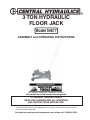
1
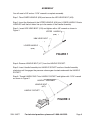
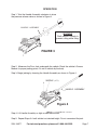
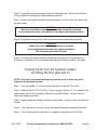
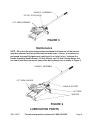
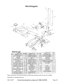
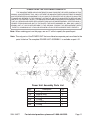
3 TON HYDRAULIC
FLOOR JACK
Model 54877
ASSEMBLY and OPERATING INSTRUCTIONS
®
3491 Mission Oaks Blvd., Camarillo, CA 93011
Visit our Web site at http://www.harborfreight.com
TO PREVENT SERIOUS INJURY,
READ AND UNDERSTAND ALL WARNINGS
AND INSTRUCTIONS BEFORE USE.
Copyright© 2005 by Harbor Freight Tools® . All rights reserved. No portion of this manual or any
artwork contained herein may be reproduced in any shape or form without the express written
consent of Harbor Freight Tools.
For technical questions and replacement parts, please call 1-800-444-3353.
SPECIFICATIONS
Capacity
Height Range
Saddle Size
Saddle Swivel
Overall Dimensions
Front Wheel Diameter
Rear Wheel Diameter
Weight
Material
6000 lbs
4-1/2”H to 19-3/8” H
4-1/4” Square
360 degrees
24”L x 14-3/8”W x 4-1/2”H
2”W X 3-1/2” DIA.
1”W X 2-5/16” DIA.
81.9 Ibs.
Plate Steel
UNPACKING
When unpacking, check to make sure all the parts shown on the Parts Lists on page
10 and 11 are included. If any parts are missing or broken, please call Harbor Freight
Tools at the number shown on the cover of this manual as soon as possible.
SAVE THIS MANUAL
You will need this manual for the safety warnings and precautions, assembly,
operating, inspection, maintenance and cleaning procedures, parts list and
assembly diagram. Keep your invoice with this manual. Write the invoice number
on the inside of the front cover. Keep this manual and invoice in a safe and dry
place for future reference.
GENERAL SAFETY PRECAUTIONS
WARNING!
READ AND UNDERSTAND ALL INSTRUCTIONS
Failure to follow all instructions listed in the following
pages may result in electric shock, fire, and/or serious injury.
SAVE THESE INSTRUCTIONS
SKU 54877
For technical questions, please call 1-800-444-3353.
Page 2
GENERAL SAFETY RULES
1.
Keep your work area clean and well lit. Cluttered work areas invite accidents.
2.
Do not operate tools and equipment in explosive atmospheres, such as in
the presence of flammable liquids, gases, or dust. Power tools and equipment create sparks which may ignite flammables.
3.
Keep bystanders, children, and visitors away while operating tools and
equipment. Distractions can cause you to lose control. Protect others in the
work area. Provide barriers or shields as needed.
4.
Stay alert. Watch what you are doing, and use common sense when
operating a power tool. Do not use tools and equipment while tired or
under the influence of drugs, alcohol, or medication. A moment of
inattention while operating power tools may result in serious personal injury.
5.
Dress properly. Do not wear loose clothing or jewelry. Contain long hair.
Keep your hair, clothing, and gloves away from moving parts. Loose
clothes, jewelry, or long hair can be caught in moving parts.
6.
Do not overreach. Keep proper footing and balance at all times. Proper
footing and balance enables better control of the tool in unexpected situations.
7.
Use safety equipment. Always wear ANSI approved safety impact goggles,
safety shoes/boots, and heavy duty work gloves when using this product.
8.
Do not force the tool. Use the correct tool for your application. The correct
tool will do the job better and safer at the rate for which it is designed.
9.
Store idle tools and equipment out of reach of children and other untrained
persons. Tools and equipment are dangerous in the hands of untrained users.
10.
Maintain tools with care. Do not use a damaged tool. Tag damaged tools “Do
not use” until repaired.
11.
If damaged, have the tool serviced before using. Check for loose screws,
misalignment or binding of moving parts, loose mounting, cracked or broken
parts, low hydraulic oil level, and any other condition that may affect its safe
operation. Many accidents are caused by poorly maintained tools.
12.
Tool service must be performed only by qualified repair personnel. Service
or maintenance performed by unqualified personnel could result in a risk of injury.
SKU 54877
For technical questions, please call 1-800-444-3353.
Page 3
13.
When servicing a tool, use only identical replacement parts. Follow
instructions in the “Inspection, Maintenance, And Cleaning” section of this
manual. Use of unauthorized parts or failure to follow maintenance instructions
may create a risk of injury.
SPECIFIC SAFETY RULES
1.
WARNING! Do not exceed the maximum lift capacity (3 Tons / 6,000
pounds) for this Floor Jack. Overloading the Jack could cause serious
personal injury and/or property damage.
2.
The Floor Jack is designed for intermittent use only. Do not use the Jack
to support a vehicle over extended periods of time. The duration of the lifting job
should be kept as short as possible.
3.
Maintain labels and nameplates on the Floor Jack. These carry important
information. If unreadable or missing, contact Harbor Freight Tools for a replacement.
4.
Prior to using the Bottle Jack, make sure to read and understand all
warnings, safety precautions, and instructions as outlined in the
manufacturer’s instruction manual for the vehicle (or object) you will lift.
5.
When lifting only one wheel, make sure to support the load immediately
with one jack stand (not included) placed under the side of the vehicle being
lifted. Align the saddle of the jack stand directly under the vehicle’s seam or a
recommended lifting point.
6.
When lifting the entire front end or rear end of a vehicle, make sure to
support the load immediately with two jack stands. Align the saddles of the jack
stands directly under the vehicle’s frame or recommended lifting points. Also make
sure the jack stands are adjusted at the same height.
7.
Make sure the Floor Jack is used only on a dry, oil/grease free, flat, level,
ground surface capable of supporting the weight of the vehicle being
lifted and any additional tools and equipment.
8.
Do not work under the vehicle without properly supporting the vehicle with
jack stands. Make sure the load and jack stands are stable before getting
under a vehicle.
SKU 54877
For technical questions, please call 1-800-444-3353.
Page 4
9.
Use the Floor Jack only on vehicles whose frames have lifting points
(on its seam or frame) capable of aligning with the Elevating Screw of the
Jack.
10.
Avoid dangerous oncoming traffic. Always use the Floor Jack as far away
from the roadside as possible.
11.
Do not use the Floor Jack with the vehicle’s engine running. Make sure
to place the vehicle’s transmission in “Park” (if automatic) or “1st Gear”
(if manual). Then set the emergency brake, and block the tires opposite the tire
being lifted.
12.
Industrial applications must follow OSHA requirements.
13.
Always keep hands, fingers, and feet away from all moving parts of the Floor
Jack when applying or releasing a load. Remain clear of the vehicle being
raised or lowered. People and animals should be kept at a safe distance when
using the Jack.
14.
Use extreme caution when applying or releasing a load. Never allow the load
to suddenly release. Slowly and carefully apply and release the load.
15.
Do not allow anyone in the vehicle while using the Bottle Jack. Keep all
bystanders a safe distance away from the vehicle.
16.
Never leave the Floor Jack unattended when the Jack is under a load.
17.
Never support both ends of the vehicle at the same time.
18.
Before lowering the Floor Jack, make sure tool trays, jack stands, and
all other tools and equipment are removed from under the vehicle.
19.
Do not stand on the Floor Jack as it may tip, causing personal injury.
20.
If changing a damaged tire, make it easier to remove the lug nuts by
slightly loosening the lug nuts before raising the tire off the ground.
21.
This Floor Jack is not to be used for aircraft purposes. Never modify the
Floor Jack in an attempt to use it for a purpose it was not designed for.
22.
WARNING! The warnings, precautions, and instructions discussed in
this manual cannot cover all possible conditions and situations that may
occur. The operator must understand that common sense and caution are
factors which cannot be built into this product, but must be supplied by the
operator.
SKU 54877
For technical questions, please call 1-800-444-3353.
Page 5
ASSEMBLY
You will need a 3/8" and an 11/16" wrench to complete assembly.
Step 1. Take LOWER HANDLE (#20) and remove the HEX HEAD BOLT (#19).
Step 2: Insert the fitted end of the UPPER HANDLE (#18) into LOWER HANDLE. Rotate
HANDLES until the bolt holes line up in the center of the Handle Assembly.
Step 3: Insert HEX HEAD BOLT (#19) and tighten with a 3/8" wrench as shown in
Figure 1.
UPPER HANDLE
(#18)
HEX HEAD BOLT
(#19)
LOWER HANDLE
(#20)
FIGURE 1
Step 4: Remove HANDLE BOLT (#17) from the HANDLE SOCKET .
Step 5: Insert Handle Assembly into HANDLE SOCKET and turn Handle Assembly
clockwise until it engages the pressure release gear located underneath the HANDLE
SOCKET.
Step 6: Thread HANDLE BOLT into HANDLE SOCKET and tighten with 11/16" wrench
as shown in Figure 2.
HANDLE ASSEMBLY
HANDLE BOLT
(#17)
HANDLE SOCKET
FIGURE 2
SKU 54877
For technical questions, please call 1-800-444-3353.
Page 6
OPERATION
Step 1: Twist the Handle Assembly clockwise to close
the pressure release valve as shown in Figure 3.
HANDLE ASSEMBLY
WARNING
Chalk vehicle’s wheels to
prevent rolling while lifting.
FIGURE 3
Step 2: Maneuver the Floor Jack underneath the vehicle. Check the vehicle’s Owners
Manual for proper jacking points. Do not lift vehicle by the body.
Step 3: Begin jacking by lowering the Handle Assembly as shown in Figure 4.
SADDLE (#31)
HANDLE ASSEMBLY
Figure 4
Step 4: Lift Handle Assembly as high as clearance allows.
Step 5: Repeat Steps 3-4 until vehicle is at desired height. Do not overextend the jack.
SKU 54877
For technical questions, please call 1-800-444-3353.
Page 7
Step 6: Place jack stands underneath vehicle at specified points. Refer to the vehicle’s
Owners Manual for proper jack stand placement locations.
Step 7: Slowly twist Handle Assembly counterclockwise. This will lower the vehicle onto
the jack stands.
WARNING:
Watch for movement of vehicle or jack stands as vehicle is lowered.
If any movement occurs, jack vehicle up and adjust jack stands properly.
Step 8: Completely lower the Floor Jack and remove from underneath the vehicle.
CAUTION:
When not in use, make sure pressure is released
by turning Handle Assembly fully counterclockwise.
This will prolong the life of the jack.
Step 9: To make sure vehicle is stable, stand away and attempt to rock the vehicle. If
movement is detected, jack up the vehicle and adjust jack stands properly. Test again.
Purging the air from the hydraulic system
and filling the floor jack with oil
NOTE: If the Floor Jack stops working it may be low on oil or there may be air
trapped in the hydraulic system.
Step 1: Turn the Handle 1-1/2 turns counterclockwise to lower the Floor Jack.
Step 2: Remove the FILL PLUG (#31A), shown on page 9 Figure # 5, It is located in the
gap between the Lift Arm Assembly (#30) and the Handle Socket. You can remove it
using a flat head screw driver.
Step 3: Rapidly pump the Handle Assembly several times to purge air from the hydraulic
system.
Step 4: Close the release valve by turning the Handle Assembly completely clockwise.
Step 5: Top off the pump with hydraulic oil if needed and replace the Oil Fill Plug.
SKU 54877
For technical questions, please call 1-800-444-3353.
Page 8
HANDLE ASSEMBLY
OIL FILL PLUG (#31A)
LIFT ARM ASSEMBLY
FIGURE 5
Maintenance
NOTE : Other than the maintenance steps mentioned in this manual, all tool service
must be performed only by qualified service technicians. Service or maintenance
performed by unqualified personnel could result in a risk of injury. Lubricate the
Handle Assembly, Handle Socket, Lift Arm, Wheels, and Lift Arm Linkage before first
use and at least twice per month (more often during heavy use) as shown in Figure 6.
HANDLE ASSEMBLY
LIFT ARM LINKAGE
HANDLE SOCKET
LIFT ARM
WHEELS
FIGURE 6
LUBRICATION POINTS
SKU 54877
For technical questions, please call 1-800-444-3353.
Page 9
Parts Diagram
Parts List
Note: Some parts are listed and shown for illustration purposes only and are not available
individually as replacement parts.
SKU 54877
For technical questions, please call 1-800-444-3353.
Page 10
PLEASE READ THE FOLLOWING CAREFULLY
THE MANUFACTURER AND/OR DISTRIBUTOR HAS PROVIDED THE PARTS DIAGRAM IN THIS
MANUAL AS A REFERENCE TOOL ONLY. NEITHER THE MANUFACTURER NOR DISTRIBUTOR MAKES
ANY REPRESENTATION OR WARRANTY OF ANY KIND TO THE BUYER THAT HE OR SHE IS QUALIFIED
TO MAKE ANY REPAIRS TO THE PRODUCT OR THAT HE OR SHE IS QUALIFIED TO REPLACE ANY
PARTS OF THE PRODUCT. IN FACT, THE MANUFACTURER AND/OR DISTRIBUTOR EXPRESSLY STATES
THAT ALL REPAIRS AND PARTS REPLACEMENTS SHOULD BE UNDERTAKEN BY CERTIFIED AND LICENSED TECHNICIANS AND NOT BY THE BUYER. THE BUYER ASSUMES ALL RISK AND LIABILITY
ARISING OUT OF HIS OR HER REPAIRS TO THE ORIGINAL PRODUCT OR REPLACEMENT PARTS
THERETO, OR ARISING OUT OF HIS OR HER INSTALLATION OF REPLACEMENT PARTS THERETO.
Note: When ordering parts on this page, use an “A” suffix to specify the specific part.
Note: The only parts of the POWER UNIT that are offered as separate parts are listed in the
parts list below. The complete POWER UNIT ASSEMBLY is available as part # 21.
Power Unit Assembly Parts List
Part
10A
11A
17A
27A
31A
34A
SKU 54877
Description
O-Ring
Backup Ring
O-Ring
O-Ring
Oil Fill Plug
O-Ring
Qty
2
2
1
1
1
1
For technical questions, please call 1-800-444-3353.
Page 11