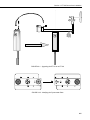
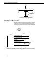
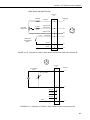
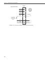
1
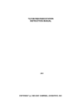
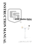
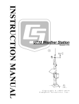
INSTRUCTION MANUAL
ET106 Weather Station
Revision: 9/02
C o p y r i g h t ( c ) 1 9 9 3 - 2 0 0 2
C a m p b e l l S c i e n t i f i c , I n c .
Warranty and Assistance
The ET106 WEATHER STATION is warranted by CAMPBELL
SCIENTIFIC, INC. to be free from defects in materials and workmanship under
normal use and service for twelve (12) months from date of shipment unless
specified otherwise. Batteries have no warranty. CAMPBELL SCIENTIFIC,
INC.'s obligation under this warranty is limited to repairing or replacing (at
CAMPBELL SCIENTIFIC, INC.'s option) defective products. The customer
shall assume all costs of removing, reinstalling, and shipping defective products
to CAMPBELL SCIENTIFIC, INC. CAMPBELL SCIENTIFIC, INC. will
return such products by surface carrier prepaid. This warranty shall not apply
to any CAMPBELL SCIENTIFIC, INC. products which have been subjected to
modification, misuse, neglect, accidents of nature, or shipping damage. This
warranty is in lieu of all other warranties, expressed or implied, including
warranties of merchantability or fitness for a particular purpose. CAMPBELL
SCIENTIFIC, INC. is not liable for special, indirect, incidental, or
consequential damages.
Products may not be returned without prior authorization. The following
contact information is for US and International customers residing in countries
served by Campbell Scientific, Inc. directly. Affiliate companies handle repairs
for customers within their territories. Please visit www.campbellsci.com to
determine which Campbell Scientific company serves your country. To obtain
a Returned Materials Authorization (RMA), contact CAMPBELL
SCIENTIFIC, INC., phone (435) 753-2342. After an applications engineer
determines the nature of the problem, an RMA number will be issued. Please
write this number clearly on the outside of the shipping container.
CAMPBELL SCIENTIFIC's shipping address is:
CAMPBELL SCIENTIFIC, INC.
RMA#_____
815 West 1800 North
Logan, Utah 84321-1784
CAMPBELL SCIENTIFIC, INC. does not accept collect calls.
ET 106 Weather Station
Table of Contents
PDF viewers note: These page numbers refer to the printed version of this document. Use
the Adobe Acrobat® bookmarks tab for links to specific sections.
1. Preparation and Siting.............................................1-1
1.1
1.2
1.3
1.4
Installation Tasks .................................................................................. 1-1
Tools Required...................................................................................... 1-2
Siting and Exposure .............................................................................. 1-5
Determining True North for Wind Vane Orientation............................ 1-7
2. ET Tower Installation...............................................2-1
2.1 Base Installation.................................................................................... 2-1
2.2 Tower Installation ................................................................................. 2-3
2.3 Tower Grounding.................................................................................. 2-4
3. ET Instrumentation Installation ..............................3-1
3.1
3.2
3.3
3.4
Enclosure, Datalogger, Power Supply................................................... 3-2
Sensor Connection ................................................................................ 3-5
Communication and Data Storage Peripherals...................................... 3-6
Sealing and Desiccating the Enclosure ............................................... 3-12
4. ET106 Sensor Arm Installation ...............................4-1
4.1 Components .......................................................................................... 4-1
4.2 Installation ............................................................................................ 4-1
4.3 Sensor Connection ................................................................................ 4-1
4.4 034A Wind Sensor Installation ............................................................. 4-2
4.5 RH and Temperature Radiation Shield ................................................. 4-3
4.6 Pyranometer .......................................................................................... 4-3
4.7 Soil Temperature Sensor (Optional) ..................................................... 4-3
4.8 Sensor Verification and Clock Set ........................................................ 4-3
4.9 Upgrading an ET101 to an ET106 ........................................................ 4-4
4.10 Sensor Schematics .............................................................................. 4-6
5. ET Software Installation ..........................................5-1
5.1 Quick Start Review ............................................................................... 5-1
6. Maintenance and Troubleshooting.........................6-1
6.1 Maintenance.......................................................................................... 6-1
6.2 Troubleshooting .................................................................................... 6-3
i
This is a blank page.
Section 1. Preparation and Siting
These guidelines apply to several different Campbell Scientific weather stations.
1.1 Installation Tasks
1.1.1 Indoors
•
Immediately upon receipt of your shipment…
⇒ Open shipping cartons.
⇒ Check contents against invoice. Contact CSI immediately about any
shortages.
•
Several days prior to the planned installation date…
⇒ Collect tools and site information (Section 1)
⇒ Assemble datalogger, communications device, and power supply in
enclosure (Section 3)
⇒ Install datalogger support software on PC (Section 5)
⇒ Establish communications between the datalogger and the PC
(Section 5)
⇒ Program datalogger, test sensors, and retrieve data (Section 5)
⇒ Trial run the tower / tripod installation, assembling as much as
possible (Section 2)
⇒ Repackage equipment for transport to the field site
1.1.2 Outdoors
•
Locate suitable site (Section 1)
•
Prepare tower or tripod base (Section 2)
•
Tripod and UT10 (3 meter tower) tower stations:
⇒ Raise tripod or tower (Section 2)
⇒ Install instrumentation enclosure (Section 3)
⇒ Install sensors (Section 4)
1-1
Section 1. Preparation and Siting
•
UT30 (10 meter tower) tower stations:
⇒ Install 3 to 10 meter level sensors (Section 4)
⇒ Raise tower (Section 2)
⇒ Install instrumentation enclosure (Section 3)
⇒ Install 0 to 3 meter level sensors (Section 4)
•
ET101 / ET106 ET Stations:
⇒ Place instrumentation enclosure low on the ET Tower (Section 3)
⇒ Install sensor option (Section 4)
⇒ Slide enclosure to top of tower and secure with correct orientation
(Section 3)
1.2 Tools Required
Tools required to install and maintain a weather station are listed below.
1.2.1 Tools for Tower Installation
All Towers
Shovel
Rake
Open end wrenches: 3/8", 7/16", ½", (2) 9/16"
Magnetic compass
6' Step ladder
CM6/CM10
Tape measure (12')
Level (12" to 24")
Small sledge hammer
Teflon tape or pipe dope
Allen hex wrench (5/64)
UT10
Tape measure (12' to 20')
Level (24" to 36")
Pick or digging bar
Claw Hammer
Materials for concrete form:
Hand saw
(4) 12" wood stakes
(1) 2"x 4"x 8' piece of lumber
(8) 8p double-head nails
(8) 16p double-head nails
Concrete trowels
(2) 1 to 1.5" thick x 24" boards to support base above forms (optional)
Concrete (0.4 cubic yards)
1-2
Section 1. Preparation and Siting
ET Tower
Tape measure (12’ to 20’)
Claw hammer
Level (24” to 36”)
Hand saw
Materials for concrete form:
(4) 1" x 2" x 12" stakes
(2) 2" x 4" x 96" lumber
(12) 8p double-head nails
(8) 16p double-head nails
20 ft form wire
½ Yard concrete
Concrete trowel, edger
Electrical Fish tape or 20 feet of small diameter rope
Wheelbarrow
UT30
Tape measure (12' and 20')
Nut driver (3/8")
Level (36" to 48")
Small sledge hammer
Pliers
Tie wire
Climbing harness
Hard hat
Haul rope (50')
Non-stretch line (20')
Wire rope cutters
Materials for B18 Base and UTEYE Anchors:
(4) Wood stakes 12"
Pick or digging bar
Concrete form materials (2"x 4" lumber, stakes, saw, hammer, nails, etc.)
Concrete trowel and edger
Materials for UTDUK Duckbill Anchors
Sledgehammer
Highlift jack
Chain (to attach jack to anchor loops)
Materials for RFM18 Base:
(3) anchors appropriate for mounting surface
(3) bolts and washers to secure base to anchors
1.2.2 Tools for Instrumentation and Maintenance
All Towers
Lock and key for enclosure
Magnetic declination angle (Section 4)
Magnetic compass
Straight bit screwdrivers (small, medium, large)
Phillips-head screwdrivers (small, medium)
Small diagonal side-cuts
Needle-nose pliers
Wire strippers
Pocket knife
Calculator
Volt / Ohm Meter
Electrical Tape
1-3
Section 1. Preparation and Siting
Step ladder (6')
Datalogger prompt sheet (Section 6)
Station manuals
Station log and pen
Open end wrenches: 3/8", 7/16", ½", (2) 9/16"
Socket wrench and 7/16" deep well socket
Adjustable wrench
Pliers
Conduit and associated tools (as required)
Felt-tipped marking pen
Claw hammer
Pipe wrench (12")
CM6/CM10
Tape measure (12')
Level (12" to 24")
Teflon tape or pipe dope
UT10
Tape measure (12' to 20')
3/8" nut driver
Level (24" to 36")
Teflon tape or pipe dope
(12) 1/4" washers (for the 015 Crossarm stand only)
Allen wrench set
UT30
Tape measure (12' to 20')
3/8" nut driver
Level (36" to 48")
Pliers
Climbing harness
Hard hats
50' haul rope
Crescent wrench
Channel-lock pliers
1/4" washers (spacers for U-bolts)
5/64" Allen hex wrench
1.2.3 Supplies for Power and Communications Options
AC Power
Wire, conduit, and junction boxes as needed
Phone Modem
Hayes compatible calling modem for PC
Phone line to weather station or junction box
Short-Haul Modem
4 Conductor communications cable from PC to weather station or junction box
6' copper ground rod and clamp for PC surge protection (optional)
1-4
Section 1. Preparation and Siting
1.3 Siting and Exposure
CAUTION
If any part of the weather station comes in contact with
power lines, you could be killed. Contact local utilities for
the location of buried utility lines before digging or driving
ground rods.
Selecting an appropriate site for the weather station is critical in order to obtain
accurate meteorological data. In general, the site should be representative of
the general area of interest, and away from the influence of obstructions such as
buildings and trees.
The weather station should not be located where sprinkler irrigation water will
strike sensors or instrument enclosure.
Some general guidelines for site selection are listed below, which were
condensed from EPA (1988)1, WMO (1983)2, and AASC (1985)3 publications.
1.3.1 Wind Speed and Direction
Wind sensors should be located over open level terrain, and at a distance of at
least ten times (EPA) the height of any nearby building, tree or other
obstruction, as illustrated in Figure 1.3-1.
Standard measurement heights:
3.0 m ± 0.1 m recommended (AASC)
2.0 m ± 0.1 m, 10.0 m ± 0.5 m optional (AASC)
10.0 m (WMO and EPA)
1.3.2 Temperature and Relative Humidity
Sensors should be located over an open level area at least 9 m (EPA) in
diameter. The surface should be covered by short grass, or where grass does
not grow, the natural earth surface. Sensors should be located at a distance of
at least four times the height of any nearby obstruction and at least 30 m (EPA)
from large paved areas. Sensors should be protected from thermal radiation,
and adequately ventilated.
Situations to avoid include:
• large industrial heat sources
• rooftops
• steep slopes
• sheltered hollows
• high vegetation
• shaded areas
• swamps
• areas where snow drifts occur
• low places holding standing water after rains
1-5
Section 1. Preparation and Siting
Standard measurement heights:
1.5 m ± 1.0 m (AASC)
1.25 - 2.0 m (WMO)
2.0 m temperature (EPA)
2.0 m and 10.0 m for temperature difference (EPA)
1.3.3 Precipitation
A rain gage should be sited on level ground that is covered with short grass or
gravel. In open areas, the distance to obstructions should be two to four times
(EPA, AASC) the height of the obstruction.
The height of the opening should be as low as possible, but should be high
enough to avoid splashing from the ground. Wind shields, such as those used
by the National Weather Service, are recommended for open areas.
Collectors should be heated, if necessary, to properly measure frozen
precipitation. The gage must be mounted above the average level of snow
accumulation in areas that experience significant snowfall.
Standard measurement heights:
1.0 m ± 1.0 cm (AASC)
30.0 cm minimum (WMO, EPA)
1.3.4 Solar Radiation
Pyranometers should be located to avoid shadows on the sensor at any time.
Mounting it on the southern most (northern hemisphere) portion of the weather
station will minimize the chance of shading from other weather station
structures. Reflective surfaces and sources of artificial radiation should be
avoided. The height at which the sensor is mounted is not critical.
1.3.5 Soil Temperature
The measurement site for soil temperature should be at least 1 m2 and typical of
the surface of interest. The ground surface should be level with respect to the
immediate area (10 m radius).
Standard measurement depths:
10.0 cm ± 1.0 cm (AASC)
5.0 cm, 10.0 cm, 50.0 cm, 100.0 cm (WMO)
1-6
Section 1. Preparation and Siting
H
REGCOMENDED
Feed
Serial
SENSORS
27115
Portland Or USA
REGCOMENDED
Feed
SENSORS
Serial 27115 27115
Portland Or USA
DEDNEMOCGER
SROSNES
51172
deeF
laireS
ASU rO dnaltroP
H
Height of tree (T)
10
T
0
1
FIGURE 1.3-1. Effect of Structure on Wind Flow
1.4 Determining True North for Wind Vane
Orientation
Magnetic declination, or other methods to find True North, should be determined
prior to installing the weather station. True North is usually found by reading a
magnetic compass and applying the correction for magnetic declination*; where
magnetic declination is the number of degrees between True North and Magnetic
North. Magnetic declination for a specific site can be obtained from a USFA map,
local airport, or through an internet service called NSSDC CGM (Section 1.4.1). A
general map showing magnetic declination for the contiguous United States is
shown in Figure 1.4-1.
Declination angles east of True North are considered negative, and are subtracted
from 0 degrees to get True North as shown Figure 1.4-2. Declination angles west
of True North are con-sidered positive, and are added to 0 degrees to get True
North as shown in Figure 1.4-3. For example, the declination for Logan, Utah is
14.5° East. True North is 360° - 14.5°, or 345.5° as read on a compass.
*
Other methods employ observations using the North Star or the sun, and
are discussed in the Quality Assurance Handbook for Air Pollution
Measurement Systems, Volume IV - Meteorological Measurements4.
1-7
Section 1. Preparation and Siting
Subtract declination from 360°
Add declination to 0°
20 W
22 E
18 W
16 W
20 E
14 W
12 W
18 E
10 W
8 W
16 E
6 W
4 W
14 E
2 W
0
12 E
10 E
8 E
6 E
4 E
2 E
FIGURE 1.4-1. Magnetic Declination for the Contiguous United States
1.4.1 NSSDC CGM Service
The NSSDC CGM (Corrected Geomagnetic) Service provides an easy way of
determining magnetic declination of a specific site. Since magnetic declination
fluctuates with time, it should be determined each time the wind vane
orientation is adjusted. It can be accessed on the world wide web at
http://nssdc.gsfc.nasa.gov/space/cgm/cgm.html
If you know the latitude and longitude of your site, fill out Form 1as shown
below for an accurate magnetic declination. If you do not know the latitude
and longitude of your site, fill out Form 2 for estimate of magnetic declination.
Note that longitude is expressed in 0 to 360 degrees east of the Greenwich
prime meridian, and that north latitudes are positive.
Query Form 1: Latitude/Longitude
Latitude/Longitude below specified in: Geographic
Year (from 1945 to 2000): 1998
Altitude above Earth's surface (km) [from 0. to 40000.]: 0
Latitude (degrees) [from -90.00 to 90.00]: 42.03
Longitude (degrees) [from 0.00 to 360.00]: 248.15
Query Form 2: Image Map
Year (from 1945 to 2000): 1998
Altitude above Earth's surface (km) [0. - 40000.]: 0
Click on map to specify location and submit: (select area on map provided)
A table containing similar information to the following will be returned after
submitting Forms 1 or 2.
1-8
Section 1. Preparation and Siting
Geographic
Lat.
Long.
Alt.
(km)
CGM
Lat.
Long.
IGRF Magnetic Field
H(nT)
D(deg)
Z(nt)
Lat.
42.03
0.
49.80
20608.
49.68
248.15
311.06
14.417
50505.
Dipole
Long.
312.14
Magnetic declination is bold in this example to show its location in the table. A
positive declination is east, while a negative declination is west. The
declination in this example is 14.417 degrees. As shown in Figure 1.4-1, the
declination for Logan, UT is east, so True North for this site is 360 - 14.417, or
345.5 degrees.
FIGURE 1.4-2. Declination Angles East of True North Are
Subtracted From 0 to Get True North
FIGURE 1.4-3. Declination Angles West of True North Are
Added to 0 to Get True North
1-9
Section 1. Preparation and Siting
References
1
EPA, (1987). On-Site Meteorological Program Guidance for Regulatory
Modeling Applications, EPA-450/4-87-013. Office of Air Quality Planning
and Standards, Research Triangle Park, North Carolina 27711.
2
WMO, (1983). Guide to Meteorological Instruments and Methods of
Observation. World Meteorological Organization No. 8, 5th edition, Geneva,
Switzerland.
3 The State Climatologist, (1985) Publication of the American Association of
State Climatologists: Height and Exposure Standards for Sensors on Automated
Weather Stations, v. 9, No. 4 October, 1985.
4 EPA, (1989). Quality Assurance Handbook for Air Pollution Measurement
Systems, EPA Office of Research and Development, Research Triangle Park,
North Carolina 27711.
1-10
Section 2. ET Tower Installation
DANGER: Do not install near power lines. If any part of the tower comes in contact with
power lines you could be KILLED. Contact local utilities for the location of buried utility
lines before digging or driving grounding rods.
CAUTION: Do not fit the 3 meter ET Tower sections together until the appropriate time.
Once attached, they cannot be detached.
The ET Tower provides a support structure for mounting the ET101 and ET106 weather
station components. Figure 2.1-1 shows a typical ET Tower installation option. The
tower is designed to withstand winds of 100 mph. The lightning rod assembly is attached
after the instrumentation enclosure is installed (Section 3.1).
Transformer
User Supplied
Junction Box
16 VAC
Power
ET Tower
Valve Box
110 VAC
Ground
Rod
Communications
Line
Direct Bury
Splices
Concrete
Base
FIGURE 2.1-1. ET Tower Installation
2.1 Base Installation
2.1.1 Supplied Components
(3) ½ inch L-Bolts
(9) ½ inch Nuts
(1) Anchor Template
Refer to Section 1 for components supplied by installer.
2-1
Section 2. ET Tower Installation
2.1.2 Installation
2-2
1.
The ET Tower attaches to a user supplied concrete foundation constructed
as shown in Figure 2.1-2.
2.
Construct the concrete form with 2" x 4" lumber and 16p nails.
3.
Assemble the template and anchor bolts. There should be two nuts below
and one nut above the template on each bolt.
4.
Clear an area large enough to set the form at the desired elevation.
5.
Dig a hole 2 feet x 2 feet x 2 feet. Lighter soils may require a deeper hole.
About 20 inches below the top of the hole, gouge a small cavity in one wall
of the hole. The cavity should be about 4 inches deep and just large
enough in diameter to insert one end of the conduit. Make certain the
cavity "points" in the direction from which power and communications
cables will come.
6.
Center the form over the hole. Adjacent to the form, drive four stakes into
the soil. Secure the leveled form to the stakes with the 8p nails.
7.
Cap the ends of the conduit with duct tape. Position the conduit and wire
into place by securing the wire to nails in the form.
8.
Fill the hole and form with approximately ½ yard of concrete. Screed the
concrete level with the top of the form. Center the template assembly over
the conduit and press into the concrete. Put 2 x 4 spacers between the
template and the top of the form. The bottom of the bolt threads should be
about ½ inch above the concrete. The template must be level in two
dimensions. Use a trowel and edger to finish.
9.
Wait 24 hours before removing the concrete form. Wait 7 days before
mounting the ET Tower.
Section 2. ET Tower Installation
SIDE VIEW
FORM
TOP VIEW
2"
FORM WIRE
NORTH
ANCHOR BOLT
24"
24"
SMALL
CAVITY
CEMENT PAD
24"
FORM WIRE
TEMPLATE
FIGURE 2.1-2. ET Tower Base Installation
2.2 Tower Installation
2.2.1 Supplied Components
(1) Upper Tower Section (Tapered)
(1) Lower Tower Section
(6) ½ inch Washers
(1) 12 foot 12 AWG Ground Cable
(1) Tower Cap
(1) 20' communications cable
(1) 20' power cable
Refer to Section 1 for components supplied by installer.
2.2.2 Installation
Attach the tower to the base as shown in Figure 2.2-1.
1.
Dig a hole close to the concrete base to access the lower conduit opening.
From the hole, trench to the power and communications sources. Remove
the duct tape from both ends of the conduit.
2.
Remove the template. Attach the two pieces of the tower. This is a
permanent connection and cannot be undone. Lay the tower on the ground
with the base next to the concrete foundation.
3.
Thread communications and power cables through the tower and conduit.
Electrical fish tape will help.
2-3
Section 2. ET Tower Installation
4.
Cut and save a 9 inch piece of 12 AWG ground wire from the 12 foot
length provided. Thread the remaining 11 foot ground wire through the
tower. Secure all wiring so it does not slip back into the tower or conduit.
5.
Place the tower cap over the tower end.
6.
Raise the tower on a still day. Place a washer on top of the two nuts on
each foundation bolt. Taking great care not to damage cables between the
tower and conduit, raise the tower and lower it onto the conduit and
mounting bolts. Install a washer and nut on each bolt and hand tighten.
Check plumb of the tower by placing a level on the north and east sides of
the lower tower section. Adjust the topmost of the two lower nuts (leveling
nut) on each bolt as necessary. When plumb is established, lock the
leveling nut in place by tightening the lowest nut against it. Tighten the
three top nuts with the wrench.
Ground Lug
12AWG Wire
4AWG Cable
FIGURE 2.2-1. Raising and Grounding the ET Tower
2.3 Tower Grounding
2.3.1 Supplied Components
(1) 5 foot 4 AWG Ground Cable
(1) Copper Ground Lug, Bolt
(1) Ground Rod, Clamp
Refer to Section 1 for components supplied by installer.
2-4
Section 2. ET Tower Installation
2.3.2 Grounding Procedure
Ground the tower as shown in Figure 2.2-1.
1.
Place the ground rod clamp on the rod. Secure it about 3 inches from the
top. Do this before the rod is driven into the ground. Be careful not to
damage the clamp with the hammer
2.
Taking care not to damage power or communications lines, drive the
ground rod close to the foundation using a fence post driver or sledge
hammer. Drive the rod at an angle if an impenetrable hardpan layer exists.
Soften hard clay soils with water if necessary.
3.
Strip 1 inch of insulation from both ends of the 4 AWG ground cable.
Strip 1 inch of insulation from the lower end of the 14 AWG ground wire.
Install the tower grounding lug to the tower base with the 7/16 bolt
provided (Figure 2.1-5). Loosen the lug's set screw and insert the 4 AWG
and 14 AWG wire. Tighten the set screw.
4.
Loosen the ground rod clamp. Insert the 4 AWG wire. Tighten the clamp
(Figure 2.1-5).
2-5
Section 2. ET Tower Installation
This is a blank page.
2-6
Section 3. ET Instrumentation
Installation
The weather station datalogger, power supply, sensor connection panel, communications
devices, and data retrieval peripherals are mounted in the ET enclosure at the locations
shown in Figure 3-1. Components include:
(1) ET Enclosure
(1) 4 unit Desiccant Pack
(1) Flat Point Screw Driver
(1) Power Supply Option
(1) Telecommunications Option
(1) 9-inch piece of 12 AWG ground wire
(1) Lightning rod and clamp
Logan, Utah
ET101
MADE IN USA
ET106
FIGURE 3-1. ET101 and ET106 Instrumentation Mounted on the ET Tower
3-1
Section 3. ET Instrumentation Installation
3.1 Enclosure, Datalogger, Power Supply
3.1.1 Battery Option Installation
a)
Alkaline Option: The BPALK houses 8 "D" cell batteries. Install it as
shown in Figure 3.1-1. Remove the external circuit board with wire and
connector by loosening the 2 Phillips head screws. Discard the external
circuit board. Mount the BPALK into the enclosure. To install the battery
pack, loosen the thumbscrew and remove the cover. Insert the battery pack
and plug the battery lead into the connector labeled "ALK".
Logan, Utah
INTERNAL BATTERY
BPALK
12V ALKALINE BATTERY PACK
TEMPORARY BATTERY
MADE IN USA
ALK Battery
Connection
FIGURE 3.1-1. Alkaline Power Mounting and Connections
Solar Panel or 16 VAC
Power Cable
YUASA
LA Battery Connection
FIGURE 3.1-2. Rechargeable Power Mounting and Connections
b) Sealed Rechargeable Battery Option: Install the kit as shown in Figure
3.1-2. An unregulated solar panel or 17 to 24 VAC must be used with the
rechargeable battery at all times. In either case, power is routed through
the Heyco fitting on the enclosure back and connected to the CHG ports by
depressing connector levers. Polarity of the CHG connection does not
matter. Install the rechargeable battery and plug the battery lead into the
connector labeled “LA”.
3-2
Section 3. ET Instrumentation Installation
3.1.2 Solar Panel Installation
FIGURE 3.1-3. Solar Panel Mounting
a)
Mount the solar panel to the tower using the mounting brackets as shown
in Figure 3.1-3. Mount the solar panel to the tower so it faces south
(northern hemisphere). Position it as high off the ground as practical,
ensuring it cannot interfere with air flow or sunlight around the sensors.
The solar panel should be oriented to receive maximum insolation over the
course of the year. Suggested tilt angles (referenced to the horizontal
plane) are listed below.
Site Latitude
Tilt Angle
0 to 10 degrees
10 degrees
11 to 20
Latitude + 5 degrees
21 to 45
Latitude + 10 degrees
46 to 65
Latitude + 15 degrees
>65
80 degrees
b) After determining the tilt angle, loosen the two bolts that attach the
mounting bracket to the panel. Adjust the angle, then tighten the bolts.
Secure the lead wire to the mast using wire ties. Make electrical
connections as described in 2b above.
3.1.3 AC Power Installation
a)
The AC power option includes a 120 VAC to 16 VAC. The transformer
should be mounted inside a user-supplied junction box according to local
electrical codes. Dangerous electrical accidents may be avoided by
locating the transformer remotely and burying a low voltage line to the
station. The low voltage will carry up to 500 feet on an 18 AWG power
cable.
3-3
Section 3. ET Instrumentation Installation
b) Shut off 110 VAC power at the main breaker. Connect the primary leads
of the transformer to 110 VAC following instructions provided with the
transformer. Connect a two-conductor cable to the secondary terminals of
the transformer. Route the cable from the transformer to the ET Enclosure
according to local electrical codes.
3.1.4 Enclosure Installation
1.
Mount and ground the ET enclosure on the ET Tower as shown in Figure
3.1-4.
a)
Place the enclosure low on the tower. Do not tighten clamps.
b) Install the sensor arm (ET106) or reduced sensor set as described in
Section 4.
9-inch
Ground
Wire
NOR
TH
Tower
Ground
Wire
FIGURE 3.1-4. Mounting and Grounding the ET Enclosure
c)
Slide the enclosure to the top of the ET tower. Position it on the north side
of the tower (northern hemisphere). The top of the enclosure should be
flush with the top of the tower, with the width of the sensor arm extending
above the tower. Tighten the clamps until the enclosure is snug. Do not
over-tighten since doing so may damage the tower or enclosure.
d) Carefully mount the lightning rod and clamp to the top of the ET Tower.
Clearance between the clamp and the enclosure is minimal. Care should be
taken not to scratch the enclosure or sensor assembly. Strip 1 inch of
insulation from the top end of the 12 AWG green tower ground wire, curl
the end and place the curled end under the head of one of the lightning rod
clamp bolts. Tighten the bolt.
3-4
Section 3. ET Instrumentation Installation
e)
Strip 1 inch of insulation from each end of the 9-inch piece of 12 AWG
ground wire. Insert one end into the brass ground lug located at the top
back of the enclosure. Curl the other end and place under the head of one
of the lightning rod clamp bolts. Tighten the bolt.
3.2 Sensor Connection
1) Install the sensor set as described in Section 4.
2) Remove the protective connector cover from the back of the ET Enclosure
by removing the two Phillips head screws. Sensors connect to one of
seven labeled bulkhead connectors as shown in Figure 3.2-1.
Earth
Ground
Stand off
Connector
Sensors
#4
TEMP
CS615
#2
WS/WD
#6
SDI 12
GYP BLOCK
#7
TEMP
#5
RAIN
(PRECIP)
#1
TEMP / RH
#3
SOLAR
RADIATION
#8
COMM
CS I/O
POWER CABLE PORT
STAND OFF
COAXIAL CONNECTION
FIGURE 3.2-1. Position of Sensor Bulkhead Connectors
3) Replace the protective connector cover after sensors are connected and
power and communications cables are installed. Ensure that all cables and
connector caps are under the cover before tightening the screws.
4) Configure sensor switch settings as shown in Figure 3.2-2 if necessary.
3-5
Section 3. ET Instrumentation Installation
604 Ohm
(LI190SB)
Open
(LI1200X)
100 Ohm
(LI200S)
1K
(HMP35C)
Open
(CS500, HMP45C)
Open
SW 12V
Open
(CS500, HMP45C)
(HMP35C)
5V
FIGURE 3.2-2. Default Sensor Switch Settings
3.3 Communication and Data Storage Peripherals
One communications kit can be mounted to the ET Enclosure back plate.
Communications kits ordered with the ET Enclosure are pre-mounted and prewired; no further connections inside the enclosure are necessary. Follow the
"External Installation" procedures outlined below to make the external
connections.
If you received a telecommunications kit separate from the ET Enclosure,
follow the "Internal Installation" procedures outlined below.
3.3.1 Phone Modems
Phone modems enable communications between the ET Enclosure and a Hayes
compatible modem in your PC over a dedicated phone line. Phone line surge
protection in built into the ET Enclosure.
P/N 10588 Cable
RJ11 Patch
Cord
Ground
Wire
Modem
FIGURE 3.3-1. Phone Modem Mounting and Connections
3-6
Section 3. ET Instrumentation Installation
3.3.1.1 Internal Installation
For installation inside the ET Enclosure, the following components are
provided in the phone modem kit:
(1) COM200 or COM300 Phone Modem
(1) 12 inch RJ-11 Patch Cord
(1) Mounting Bracket
(4) Screws
(1) 12 inch 14 AWG Ground Wire
Install the phone modem as shown in Figure 3.3-1.
1.
Attach the modem to the modem bracket with the 4 screws provided.
Mount the modem and bracket into the ET Enclosure with the 3 prethreaded screws on the mounting plate.
2.
Connect the modem 9-pin port to the ET Enclosure port with the
P/N 10588 ribbon cable supplied with the ET Enclosure.
3.
Connect the modem RJ-ll jack to the ET Enclosure RJ-11 jack with the RJll patch cord.
4.
Connect the modem ground port to the ET Enclosure ground with the 14
AWG ground wire.
3.3.1.2 External Installation
The following modem kit components are used to make the external
connections:
(1) Direct Bury Splice Kit
(1) 20 foot Telephone Patch Cord with Connector
1) Connect the 20 foot patch cord to connector #8 on the external back panel,
under the protective cover.
2) Splice the labeled "Tip" and "Ring" lines of the patch cord to the telephone
service line. Use the direct bury splice kit when splices are in a valve box
or buried.
3.3.2 Cellular Phone Transceiver
CAUTION
Do not power the transceiver until the antenna is
connected!
Cellular service and programming of your transceiver must be coordinated with
your local cellular provider. Cellular service enables communication between
the ET Enclosure and the Hayes compatible modem at your PC without
hardwire connections. The cellular transceiver kit must be purchased with one
of the phone modem kits.
3-7
Section 3. ET Instrumentation Installation
3.3.2.1 Internal Installation
For installation inside the ET Enclosure, the following components are
provided in the cell phone modem kit:
(1) COM100 Transceiver, Power Connector
(1) Mounting Bracket
(6) Screws
(1) 12 inch Coaxial Patch Cable
Install the phone modem and cellular transceiver as shown in Figure 3.3-2.
1.
2.
3.
4.
5.
6.
3-8
Attach the modem to the modem bracket with 4 of the screws provided.
Attach the cellular transceiver with 2 of the screws provided. Mount the
bracket into the ET Enclosure with the 3 pre-threaded screws on the
mounting plate.
Mount the RJ11C Interface to the side of the battery bracket.
Connect the modem 9-pin port to the ET Enclosure port with the blue 9 pin
ribbon cable supplied with the ET Enclosure.
Connect the modem RJ-ll jack to the RJ11C Interface with the RJ-ll patch
cord. Connect the cellular transceiver coaxial connection to the bulkhead
coaxial connector with the coaxial patch cable.
Connect the modem ground terminal to the recessed ET Enclosure ground
with the 14 AWG ground wire.
Do this step after the antenna is connected (Section 3.3.2.2). Connect the
transceiver power cord assembly to the transceiver's 25 pin connector.
Connect the red 12 V lead to the 12V terminal in the ET Enclosure.
Connect the black ground lead to the GND terminal. Connect the green
power control lead to the RCV+ and terminal.
Section 3. ET Instrumentation Installation
Motorola M600
Transceiver
COM200 or VS1
Telephone Modem
Green Modem
Ground Wire to
Modem “GND”
Terminal
Green Modem Ground
Wire to Recessed
“GND” Lug
Blue 9 Pin
Ribbon Cable
(1 Extra Connector)
Cellular Power
Connector
RJ11C
Patch Cord
Cellular Handset
Connector
(normally not used)
Black Transceiver
Ground Wire to “GND”
Red Transceiver
12 Volt Wire
to “12 V”
Green Transceiver
Control Wire to“RCV+”
(Program Control Port 2)
Power
Indicator
(do not press)
RJ11C Interface
Coax Bulkhead
Connector
Antenna Coax
Cable
Battery
FIGURE 3.3-2. Cellular Phone Mounting and Connection
3-9
Section 3. ET Instrumentation Installation
3.3.2.2 External Installation
The following cellular kit components are used to make the external
connections:
(1) Cellular Antenna
(1) 9 foot Coaxial Antenna Cable
(1) Antenna Mounting Bracket
FIGURE 3.3-3. Cellular Phone Antenna Mounting
1) Mount the antenna to the ET Tower as shown in Figure 3.3-3.
2) Connect the antenna to the external coaxial bulkhead connector with the
9-foot antenna cable.
3.3.3 Short-Haul Modem
CAMPBELL
SCIENTIFIC LTD
SC932 - S/N E1055
QC
Short-haul modems enable communication between a datalogger and computer
over two twisted pairs of wires. The maximum distance between modems is
determined by baud rate and wire gauge. At 9600 baud, the approximate range
is 4.0 miles. DCE / DTE switches on the modems are set to DCE.
FIGURE 3.3-4. Short-Haul Modem Mounting and Connection
3-10
Section 3. ET Instrumentation Installation
3.3.3.1 Internal Installation
For installation inside the ET Enclosure, the following components are
provided in the short-haul modem kit:
(1) SC932C Interface
(1) Rad Modem
(1) Rad/SC932C Mounting Bracket
(4) Screws
(1) 12 inch 4-wire patch cable
Install the short-haul modems as shown in Figure 3.3-4 and 3.3-5.
1.
Mount the Rad / SC932C mounting bracket into the ET Enclosure with the
3 pre-threaded screws provided.
2.
Connect the Rad Modem and SC932C. Strap them into the mounting
bracket under the Velcro strap.
3.
Connect the SC932C 9-pin port to the internal ET Enclosure 9-pin port
with the blue ribbon cable provided.
4.
Wire the Rad Modem to the ET Enclosure with the 12-inch patch cord.
Match wire labels to wiring panel labels on both the ET Enclosure and the
Rad Modem (+XMT to +XMT, etc.). A small screwdriver in provided
with the ET Enclosure to access the Rad Modem connections.
3.3.3.2 External Installation
The following short-haul kit components are used to make the external
connections:
At the ET Enclosure:
(1) 20 foot 4-Wire Patch Cable
(2) 2 Direct Bury Splice Kits
(1) Length of User Supplied Wire (Supplier: Anixter, p/n F-02P22BPN,
Phone 847-677-2600)
At the PC:
(1) Rad Modem
(1) 5 foot 4-wire Patch Cable
(1) 10 foot 14 AWG Ground Wire
(1) Surge Protector and Case
1) Connect the 20 foot patch cable to connector #8 on the external back panel
of the ET Enclosure. Splice this cable to the user supplied cable, using the
direct bury splice kits.
2) Mount the surge protector to a flat surface within 10 inches of the PC's
serial port. Ground the center terminal to an earth (or building) ground
using the 14 AWG wire.
3-11
Section 3. ET Instrumentation Installation
3) Connect the 5-foot patch cord to the Rad Modem. Fasten the cable to the
strain relief tab with a cable tie. Connect the Rad to the PC's serial port
either directly (25 pin port) or through a 9 to 25 pin serial converter.
4) Route the user-supplied cable from the remote splice to the surge protector.
Connect it and the 5-foot patch cord to the surge protector.
- RCV (white)
CQ
+ RCV (green)
ET106 ENCLOSURE
ET106 ENCLOSURE
LLEBPMAC
DTL CIFITNEICS
5501E N/S - 239CS
- XMT (black)
+ XMT (red)
+ RCV (red)
- RCV (black)
+ XMT (green)
- XMT (white)
To # 8
External Connector
Surge
Protector
PC
SRM-5A
1
+ RCV (red)
- RCV (black)
2
User
Supplied
Cable
Splices
1
+ RCV
RED
2
- RCV
BLACK
+ XMT (green)
3
- XMT (white)
3
4
4
+ XMT
GREEN
- XMT
WHITE
Earth Ground
FIGURE 3.3-5. Short-Haul Modem Wiring Diagram
3.4 Sealing and Desiccating the Enclosure
The ET Enclosure is supplied with a desiccant pack. The desiccant maintains a
low humidity in the enclosure to minimize the chance of condensation on the
instrumentation. Desiccant should be changed when the internal ET Enclosure
humidity sensor measures 30% or higher. Install the desiccant as shown in
Figure 3.4-1. Keep unused desiccant tightly sealed in an airtight container.
1) Take the desiccant pack out of its sealed plastic bag. Place it under the
desiccant strap just before leaving the station.
2) Be sure to close the enclosure hasp securely. A padlock may be used on
the latch for extra security.
3-12
Section 3. ET Instrumentation Installation
Desiccant
Pack
DO NOT EAT
UNITED DESICCAN
101CHRISTINE, BELEN,
TS-GATES
NEW MEXICO 87002
DESI PAK
SPECIFICATION MIL-D-3464
TYPE I &II
REACTIVATION TIME
IN-BAG 16 HOURS
AT 250 O F
DESICCANT
CONTENTS
PACKAGE USE
ACTIVATED
4
AND STATIC
BAGGED FOR
UNITS
DEHUMIDIFICATION
DO NOT EAT
UNITED DESICCAN
101CHRISTINE, BELEN,
TS-GATES
NEW MEXICO 87002
DESI PAK
SPECIFICATION MIL-D-3464
TYPE I &II
REACTIVATION TIME
IN-BAG 16 HOURS
AT 250O F
DESICCANT
CONTENTS
PACKAGE USE
ACTIVATED
4
AND STATIC
BAGGED FOR
UNITS
DEHUMIDIFICATION
FIGURE 3.4-1. Desiccant Installation
3-13
Section 3. ET Instrumentation Installation
This is a blank page.
3-14
Section 4. ET106 Sensor Arm
Installation
4.1 Components
(1) ET106 Sensor Arm
(1) Met One 034A Wind Sensor
(1) 034A Mounting Shaft
(1) Radiation Shield
4.2 Installation
Install the ET106 Sensor Arm after the ET Enclosure is mounted low on the ET
Tower. You may need to temporarily remove communications option. Mount
the sensor arm as shown in Figure 4.2-1 without the wind sensor attached.
ET Sensor
Arm
ET Enclosure
Screws
(4)
FIGURE 4.2-1. ET106 Sensor Arm Mounting
1) Remove the cover from the ET Enclosure
2) Place the sensor arm on top of the enclosure, lining up the four threaded
holes on the under side of the arm with the four holes in the top of the
enclosure. Attach the arm to the enclosure by inserting and tightening four
Phillips head screws. Adjust the position of the ET Enclosure so that the
sensor arm is oriented along a due east to due west axis.
4.3 Sensor Connection
Refer to Section 3 for sensor connection details.
4-1
Section 4. ET106 Sensor Arm Installation
4.4 034A Wind Sensor Installation
Install the 034A Wind Sensor as shown in Figure 4.4-1 after the sensor arm is
securely installed. The wind vane is oriented after the datalogger has been
programmed (Section 5), and the location of True North has been determined
(Section 1.2). Orientation is most easily done with two people, one to aim and
adjust the sensor, while the other observes the wind direction displayed by
CR10KD Keyboard Display or a laptop PC.
FIGURE 4.4-1. Wind and RH/Temperature Sensor Installation
1) Place the 034A in the 034A Mounting Shaft pointing the vane due south.
Tighten the alignment screw.
2) Attach the 034A and mounting shaft to the sensor arm. Insert the mounting
shaft into the U-bolt clamp. Adjust sensor height to 2 or 3 meters by
moving the mounting shaft up or down in the clamp. Lightly tighten clamp
nuts.
3) Attach the 034A connector to the 034A.
4) Establish a reference point on the horizon for True North.
5) Sighting down the instrument center line, aim the counter weight at True
North. Display input location #8 (Section 4.6) for wind direction using the
*6 Mode of the datalogger, or the Monitor Mode of PC208.
6) While holding the wind vane position, slowly rotate the sensor base until
the datalogger indicates 0 degrees. Securely tighten the clamp nuts.
4-2
Section 4. ET106 Sensor Arm Installation
4.5 RH and Temperature Radiation Shield
Mount the radiation shield to the sensor arm as shown in Figure 4.4-1. Place
the RH and temperature assembly inside the shield shaft. Attach the shield to
the sensor arm with the two screws.
4.6 Pyranometer
Level the pyranometer as indicated in Figure 4.6-1. Adjust the three leveling
screws until the bubble level indicates plumb. Remove the red cap from the
pyranometer.
Leveling
Screws
FIGURE 4.6-1. Pyranometer Leveling
4.7 Soil Temperature Sensor (Optional)
Bury the soil temperature sensor at the desired depth. To minimize solar
loading of the sensor cable, bury the cable between the tower base and the
sensor.
4.8 Sensor Verification and Clock Set
Check the measurements of all sensors after the datalogger is programmed.
Display measurements using the *6 Mode with the CR10KD (refer to the
laminated prompt sheet, or the Monitor Mode of the PC208 Datalogger
Support Software.
4-3
Section 4. ET106 Sensor Arm Installation
Input
Location
Parameter
Normal
Range
1
Battery (Volt)
9.6 to 14.0 Volts
2
Enclosure Temperature (°C)
Close to air temperature
3
Air Temperature (°C)
-40° to +50°
4
Air Temperature (°F)
-40° to +122°
5
RH (%)
0 to 100%
-2
6
Solar Radiation(kW m )
0 to 1.2 kW m-2
7
Wind Speed (mph)
0 to 110 mph
8
Wind Direction (°)
0 to 359
9
Rain Fall (inches)
0 to .2
10
Soil Temperature 107
-40° to +122°F
28
Enclosure RH
-40° to +50°C or 0% to 30% when
sealed for several hours
Display and set clock time using the *5 mode with the CR10KD (refer to the
laminated prompt sheet).
4.9 Upgrading an ET101 to an ET106
The ET101 can be upgraded to an ET106 by installing part number 10574
ET101 to ET106 Upgrade Kit as shown in Figure 4.9-1, 4.9-2, and 4.9-3.
1) Loosen the three leveling screws on the ET101 sensor bracket. Remove
the bracket.
2) Move the three leveling screws on the bracket as shown.
3) Remove the white temperature sensor from the bracket by removing the
three screws under its base.
4) Reverse the orientation of the bracket, and place it on the upgrade arm.
Thread the three leveling screws into the pre-threaded holes two to three
turns.
5) Install the sensor arm as described in Sections 4.1 to 4.7.
4-4
Section 4. ET106 Sensor Arm Installation
ET101 to ET106
Logan, Utah
MADE IN USA
FIGURE 4.9-1. Upgrading the ET101 to an ET106
FIGURE 4.9-2. Modifying the Pyranometer Plate
4-5
Section 4. ET106 Sensor Arm Installation
Metal Washers
FIGURE 4.9-3. Installing Leveling Screws
4.10 Sensor Schematics
Schematics of ET106 sensors and associated connectors are provided in
Figures 4.10-1, 4.10-2, 4.10-3, and 4.10-4 for help in troubleshooting.
Knowledge of the schematics is not necessary for routine installation and
maintenance.
3
4
2
6
1
5
Connector
Pin
Air Temperature and
Relative Humidity
Sensor
Relative Humidity (0-1VDC)
1
Air Temperature (0-1VDC)
2
Not Used
3
12V Switched Supply
4
Analog Ground
5
Shield
6
Datalogger
1H
1L
12VDC Switched
Supply
AG
G
FIGURE 4.10-1. Schematic of CS500-LC RH and Temperature Probe and Connector #1
4-6
Section 4. ET106 Sensor Arm Installation
Wind Speed and Wind Direction
Connector
Pin
10K OHM
1K OHM
10K OHM
Potentiometer
Excitation
3
Wind Direction
Signal Return
1
Datalogger
E2
2H
3
4
2
6
Analog Ground
2
Wind Speed
4
Pulse
Magnetically
Activated Reed
Switch
Ground
Shield
1
5
AG
P1
5
G
6
G
FIGURE 4.10-2. Schematic of 034A-LC Wind Speed and Direction Probe and Connector #2
3
4
2
6
1
5
Connector
Pin
Solar Radiation
Sensor
Datalogger
1
3H
40.2 - 90.2 OHM
2
3L
Shield
Not Used
3
Not Used
4
Not Used
5
6
G
FIGURE 4.10-3. Schematic of LI200X-LC Solar Radiation Sensor and Connector #3
4-7
Section 4. ET106 Sensor Arm Installation
Connector
Pin
Tipping Rain Bucket
Not Used
1
3
4
2
6
Not Used
2
Not Used
4
Pulse
3
Ground
5
1
5
Datalogger
Magnetically
Activated Reed
Switch
Shield
P2
G
6
G
FIGURE 4.10-4. Schematic of TE525-LC Rain Sensor and Connector #5
4-8
Section 5. ET Software Installation
The ET Evapotranspiration Stations are supported by PC120 "ETPro" for MS-DOS.
ETPro is used to write and download the station program, and to retrieve and report data.
ETPro works in conjunction with PC208 Datalogger Support Software. PC120 and
PC208 each have their own manual, which should be consulted for installation procedures
and operational details.
5.1 Quick Start Review
1) Start PC120 by entering "ET" at the DOS prompt (refer to the PC120
manual).
2) Create the ET datalogger program by clicking your mouse cursor on the
main screen "Edit," then on "Create Station Program" (Edit | Create Station
Program). Follow the prompts until you return to the main screen.
3) Click on "Edit | Communications Param." to set up the PC-to-ET
telecommunications link. Check the link by attempting to set the clock
(Maintenance | Set Clock).
4) Download the program by selecting "Maintenance | Download Station
Prog."
5) After at least an hour, retrieve data from the ET datalogger to a comma
delimited ASCII file called WEATHER.DAT by selecting "Data | Collect
Data."
6) Weather reports can be generated by selecting "Reports | Hourly
Summary" or "Reports | Daily Summary."
5-1
Section 5. ET Software Installation
This is a blank page.
5-2
Section 6. Maintenance and
Troubleshooting
These guidelines apply to several different Campbell Scientific weather stations.
6.1 Maintenance
Proper maintenance of weather station components is essential to obtain
accurate data. Equipment must be in good operating condition, which requires
a program of regular inspection and maintenance. Routine and simple
maintenance can be accomplished by the person in charge of the weather
station. More difficult maintenance such as sensor calibration, sensor
performance testing (i.e., bearing torque), and sensor component replacement,
generally requires a skilled technician, or that the instrument be sent to
Campbell Scientific or the manufacturer.
A station log should be maintained for each weather station that includes serial
numbers, dates that the site was visited, and maintenance that was performed.
6.1.1 Instrumentation Maintenance
The instrumentation requires a minimum of routine maintenance. A few
preventative maintenance steps will optimize battery life and decrease the
chances of datalogger failure.
6.1.2 Batteries
Instruction 10 can be used to measure battery voltage. By recording battery
voltage the user can determine how long a fresh set of batteries will last (see the
Installation Section of the datalogger Operator's Manual for cold temperature
effects on alkaline batteries). Short Cut and ETPro automatically program the
weather station to measure battery voltage.
When alkaline batteries are used, the battery voltage should not be allowed to
drop below 9.6 VDC before replacement. Where CR10 or 21X dataloggers are
used in the instrumentation, an external battery must be used to maintain power
to the datalogger when changing batteries, otherwise the clock, program, and
data will be lost (refer to the Installation Section of the datalogger's Operator's
Manual for details). When not in use, remove the eight cells to eliminate
potential corrosion of the contact points, and store in a cool dry place.
Rechargeable power supplies should be connected to an AC transformer or
unregulated solar panel at all times. The charge indicating diode should be
"ON" when voltage to the charging circuitry is present. Be aware of battery
voltage that consistently decreases over time, which indicates a failure in the
charging circuitry.
6-1
Section 6. Maintenance and Troubleshooting
6.1.3 Desiccant
Enclosure humidity is monitored in the ET Enclosure and MetData1 systems by
an RH chip incorporated into the connector board. Change the desiccant packs
when the enclosure RH exceeds 35%. The RH chip should be changed every 3
to 5 years.
In standard weather stations, a humidity indicator card is provided with the
enclosure. A small RH sensor (10162) can be purchased separately to record
the RH inside the enclosure. Change the desiccant when either the card or the
sensor read about 35% RH.
Desiccant may be ordered through Campbell Scientific (DSC 20/4).
Desiccant packs inside of the dataloggers do not require replacement under
normal conditions.
6.1.4 Sensor Maintenance
Sensor maintenance should be performed at regular intervals, depending on the
desired accuracy and the conditions of use. A suggested maintenance schedule is
outlined below.
1 week
•
Check the pyranometer for level and contamination. Gently clean, if
needed.
•
Visually inspect the wind sensors and radiation shield.
1 month
•
Check the rain gage funnel for debris and level.
•
Do a visual/audio inspection of the anemometer at low wind speeds.
•
Check the filter of the temperature/humidity sensor for contamination.
General Maintenance
•
An occasional cleaning of the glass on the solar panel will improve its
efficiency.
•
Check sensor leads and cables for cracking, deterioration, proper routing,
and strain relief.
•
Check the tripod or tower for structural damage, proper alignment, and for
level/plumb.
6 months
6-2
•
Clean the temperature/humidity sensor.
•
Clean the Gill Radiation Shield.
Section 6. Maintenance and Troubleshooting
1 year
•
Replace anemometer bearings.
•
Calibrate the rain gage.
•
Calibrate the HMP45C/HMP35C probe.
•
Check calibration of CS500 RH Probe; replace RH chip if necessary.
•
Check internal RH chip (MetData1 and ET101/106 only). Replace if >5%
off.
2 years
•
Calibrate the solar radiation sensors (some users suggest yearly).
•
Calibrate the temperature sensor.
•
Replace the wind vane potentiometer and bearings.
4 - 5 years
•
Replace sensor cables as required.
6.2 Troubleshooting
6.2.1 No Response Using the Keypad
Check keypad response after each of the following steps.
A. Make sure the battery has been installed, and the power switch, if any, is
"ON" (Section 7).
B. Use a voltmeter to measure the voltage on the 12 V and G terminals; the
voltage must be between 9.6 and 16 VDC.
C. Disconnect any sensor or peripheral wires connected to the 5 V and 12 V
terminals.
D. Disconnect any communications or storage peripherals from the
datalogger.
E. Reset the datalogger by turning the power switch to "OFF", then to "ON"
or disconnecting and reconnecting the battery.
F.
If still no response, call Campbell Scientific.
6.2.2 No Response from Datalogger through SC32A or Modem
Peripheral
At the datalogger:
A. Make sure the battery has been installed, and the power switch, if any, is
"ON" (Section 7).
B. Use a voltmeter to measure the voltage on the 12 V and G terminals; the
voltage must be between 9.6 and 16 V DC.
6-3
Section 6. Maintenance and Troubleshooting
C. Make sure the datalogger is connected to the modem, and the modem is
properly configured and cabled (Section 9).
At the computer:
D. Make sure the Station File is configured correctly (PC208 Manual).
E. Check the cable(s) between the serial port and the modem. If cables have
not been purchased through Campbell Scientific, check for the following
configuration using an ohm meter:
25-pin serial port:
computer end
modem end
2
3
7
20
2
3
7
20
9-pin serial port:
computer end
2
3
4
5
F.
modem end
3
2
20
7
Make sure the modem is properly configured and cabled (Section 9).
G. If still no response, call Campbell Scientific.
6.2.3 -99999 Displayed in an Input Location
A. Make sure the battery voltage is between 9.6 and 16 VDC.
B. With the MetData1 or ET106, verify that the sensor is connected to the
proper bulkhead connector. With custom weather stations, verify the
sensor is wired to the analog channel specified in the measurement
instruction or Short Cut .FSL file (single-ended channels are not labeled on
the older silver-colored wiring panels and are numbered sequentially
starting at 1H; i.e. 1L is single-ended channel 2).
C. Make sure the Range parameter in the measurement instruction covers the
full scale voltage output by the sensor.
6.2.4 Unreasonable Results Displayed in an Input Location
A. Inspect the sensor for damage and/or contamination.
B. Make sure the sensor is properly wired to the datalogger.
C. Check the multiplier and offset parameters in the measurement instruction.
6-4
Section 6. Maintenance and Troubleshooting
6.2.5 6999 or 99999 Stored in Final Storage (or Storage
Module)
A. Final Storage format limitations exceeded (any number larger than 6999 in
low resolution, or 99999 in high-resolution format is stored as the
maximum number). Change the datalogger program.
6-5
Section 6. Maintenance and Troubleshooting
This is a blank page.
6-6
This is a blank page.
Campbell Scientific Companies
Campbell Scientific, Inc. (CSI)
815 West 1800 North
Logan, Utah 84321
UNITED STATES
www.campbellsci.com
[email protected]
Campbell Scientific Africa Pty. Ltd. (CSAf)
PO Box 2450
Somerset West 7129
SOUTH AFRICA
www.csafrica.co.za
[email protected]
Campbell Scientific Australia Pty. Ltd. (CSA)
PO Box 444
Thuringowa Central
QLD 4812 AUSTRALIA
www.campbellsci.com.au
[email protected]
Campbell Scientific do Brazil Ltda. (CSB)
Rua Luisa Crapsi Orsi, 15 Butantã
CEP: 005543-000 São Paulo SP BRAZIL
www.campbellsci.com.br
[email protected]
Campbell Scientific Canada Corp. (CSC)
11564 - 149th Street NW
Edmonton, Alberta T5M 1W7
CANADA
www.campbellsci.ca
[email protected]
Campbell Scientific Ltd. (CSL)
Campbell Park
80 Hathern Road
Shepshed, Loughborough LE12 9GX
UNITED KINGDOM
www.campbellsci.co.uk
[email protected]
Campbell Scientific Ltd. (France)
Miniparc du Verger - Bat. H
1, rue de Terre Neuve - Les Ulis
91967 COURTABOEUF CEDEX
FRANCE
www.campbellsci.fr
[email protected]
Campbell Scientific Spain, S. L.
Psg. Font 14, local 8
08013 Barcelona
SPAIN
www.campbellsci.es
[email protected]
Please visit www.campbellsci.com to obtain contact information for your local US or International representative.