1
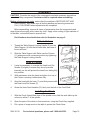
5-SPEED DRILL PRESS
Model 38119
Set up and Operating Instructions
Visit our website at: http://www.harborfreight.com
Read this material before using this product.
Failure to do so can result in serious injury.
Save this manual.
Copyright© 1998 by Harbor Freight Tools®. All rights reserved. No portion of this manual or any artwork contained
herein may be reproduced in any shape or form without the express written consent of Harbor Freight Tools. Diagrams within this manual may not be drawn proportionally. Due to continuing improvements, actual product may
differ slightly from the product described herein. Tools required for assembly and service may not be included.
For technical questions or replacement parts, please call 1-800-444-3353.
Revised Manual 10e
Contents
Important SAFETY
Information���������������������������� 3
General Tool Safety
Warnings�������������������������������������� 3
Drill Press Safety Warnings5
Vibration Safety�������������������� 6
Grounding Instructions����� 6
Grounded Tools: Tools
with Three Prong Plugs������� 6
Unpacking���������������������������������� 8
Features������������������������������������ 9
Specifications�������������������������� 9
Assembly���������������������������������� 10
Table to Column������������������������ 10
CHANGING DRILL (SPINDLE)
SPEED�������������������������������������������12
DRILL SPEED TABLE���������������������� 13
Operation�������������������������������� 13
Cutting Speeds��������������������������� 14
After Operation������������������� 14
Maintenance��������������������������� 15
Troubleshooting���������������������� 15
Parts Lists and Assembly
Diagrams�������������������������������� 16
Pulley Assembly����������������������� 16
Head Assembly��������������������������� 17
Quill Assembly��������������������������� 18
Base and Table Assembly������ 18
LIMITED 90 DAY WARRANTY���� 19
Head to Column������������������������� 10
Installing the Chuck��������������� 10
Pulley Cover Knob������������������� 11
Adjusting the Drive Belt������� 11
Settings and Adjustments11
TO ADJUST THE TABLE����������������� 11
SETTING THE REQUIRED ANGLE� 12
TO SET DRILLING DEPTH�������������� 12
SKU 38119
For technical questions, please call 1-800-444-3353.
Page 2
CAUTION, used
with the safety
alert symbol, indicates a
hazardous situation which, if
not avoided, could result in
minor or moderate injury.
Save This Manual
Keep this manual for the safety
warnings and precautions, assembly,
operating, inspection, maintenance and
cleaning procedures. Write the product’s
serial number in the back of the manual
near the assembly diagram (or month
and year of purchase if product has no
number). Keep this manual and the
receipt in a safe and dry place for future
reference.
NOTICE is used to
address practices
not related to personal injury.
CAUTION, without
the safety alert
symbol, is used to address
practices not related to
personal injury.
Important SAFETY
Information
General Tool Safety Warnings
In this manual, on the labeling,
and all other information
provided with this product:
This is the safety alert
symbol. It is used to alert
you to potential personal
injury hazards. Obey all
safety messages that
follow this symbol to avoid
possible injury or death.
DANGER indicates
a hazardous
situation which, if not
avoided, will result in death or
serious injury.
WARNING
indicates a
hazardous situation which, if
not avoided, could result in
death or serious injury.
SKU 38119
WARNING Read all safety
warnings and instructions.
Failure to follow the warnings and
instructions may result in electric
shock, fire and/or serious injury.
Save all warnings and
instructions for future reference.
1.
KEEP GUARDS IN PLACE and in
working order.
2.
REMOVE ADJUSTING KEYS AND
WRENCHES. Form habit of checking
to see that keys and adjusting
wrenches are removed from tool
before turning it on.
3.
KEEP WORK AREA CLEAN.
Cluttered areas and benches invite
accidents.
4.
DON’T USE IN DANGEROUS
ENVIRONMENT. Don’t use power
tools in damp or wet locations, or
expose them to rain. Keep work area
well lighted.
For technical questions, please call 1-800-444-3353.
Page 3
5.
KEEP CHILDREN AWAY. All visitors
should be kept safe distance from
work area.
6.
MAKE WORKSHOP KID PROOF
with padlocks, master switches, or by
removing starter keys.
7.
DON’T FORCE TOOL. It will do the
job better and safer at the rate for
which it was designed.
8.
USE RIGHT TOOL. Don’t force tool
or attachment to do a job for which it
was not designed.
RECOMMENDED MINIMUM WIRE
GAUGE FOR EXTENSION CORDS
(120 VOLT)
NAMEPLATE
AMPERES
(at full load)
EXTENSION CORD
LENGTH
25’
50’ 100’ 150’
0–6
18
16
16
14
6.1 – 10
18
16
14
12
10.1 – 12
16
16
14
12
12.1 – 16
14
12
Do not use.
TABLE A
9.
USE PROPER EXTENSION CORD.
Make sure your extension cord
is in good condition. When using
an extension cord, be sure to use
one heavy enough to carry the
current your product will draw. An
undersized cord will cause a drop in
line voltage resulting in loss of power
and overheating. Table A shows the
correct size to use depending on cord
length and nameplate ampere rating.
If in doubt, use the next heavier gage.
The smaller the gage number, the
heavier the cord.
10. WEAR PROPER APPAREL. Do
not wear loose clothing, gloves,
neckties, rings, bracelets, or other
SKU 38119
jewelry which may get caught in
moving parts. Nonslip footwear is
recommended. Wear protective hair
covering to contain long hair.
11. ALWAYS USE SAFETY GLASSES.
Also use face or dust mask if
cutting operation is dusty. Everyday
eyeglasses only have impact
resistant lenses, they are NOT safety
glasses.
12. SECURE WORK. Use clamps or a
vise to hold work when practical. It’s
safer than using your hand and it
frees both hands to operate tool.
13. DON’T OVERREACH. Keep proper
footing and balance at all times.
14. MAINTAIN TOOLS WITH CARE.
Keep tools sharp and clean for best
and safest performance. Follow
instructions for lubricating and
changing accessories.
15. DISCONNECT TOOLS before
servicing; when changing
accessories, such as blades, bits,
cutters, and the like.
16. REDUCE THE RISK OF
UNINTENTIONAL STARTING. Make
sure switch is in off position before
plugging in.
17. USE RECOMMENDED
ACCESSORIES. Consult the
owner’s manual for recommended
accessories. The use of improper
accessories may cause risk of injury
to persons.
18. NEVER STAND ON TOOL. Serious
injury could occur if the tool is tipped
or if the cutting tool is unintentionally
contacted.
For technical questions, please call 1-800-444-3353.
Page 4
19. CHECK DAMAGED PARTS. Before
further use of the tool, a guard or
other part that is damaged should be
carefully checked to determine that
it will operate properly and perform
its intended function – check for
alignment of moving parts, binding
of moving parts, breakage of parts,
mounting, and any other conditions
that may affect its operation. A guard
or other part that is damaged should
be properly repaired or replaced.
20. DIRECTION OF FEED. Feed work
into a blade or cutter against the
direction of rotation of the blade or
cutter only.
21. NEVER LEAVE TOOL RUNNING
UNATTENDED. TURN POWER OFF.
Don’t leave tool until it comes to a
complete stop.
Drill Press Safety Warnings
For Your Own Safety Read Instruction
Manual Before Operating Drill Press
1.
Wear eye protection.
2.
Do not wear gloves, necktie, or loose
clothing.
3.
Clamp workpiece or brace against
column to prevent rotation.
4.
Use recommended speed for drill
accessory and workpiece material.
5.
The use of accessories or
attachments not recommended by
the manufacturer may result in a risk
of injury to persons.
6.
When servicing use only identical
replacement parts.
7.
Only use safety equipment that has
been approved by an appropriate
SKU 38119
standards agency. Unapproved
safety equipment may not provide
adequate protection. Eye protection
must be ANSI-approved and
breathing protection must be NIOSHapproved for the specific hazards in
the work area.
8.
Maintain labels and nameplates on
the tool. These carry important safety
information. If unreadable or missing,
contact Harbor Freight Tools for a
replacement.
9.
Avoid unintentional starting. Prepare
to begin work before turning on the
tool.
10. People with pacemakers should
consult their physician(s) before
use. Electromagnetic fields in close
proximity to heart pacemaker could
cause pacemaker interference or
pacemaker failure. In addition,
people with pacemakers should:
• Avoid operating alone.
• Do not use with power switch locked
on.
• Properly maintain and inspect to
avoid electrical shock.
• Any power cord must be properly
grounded. Ground Fault Circuit
Interrupter (GFCI) should also be
implemented – it prevents sustained
electrical shock.
11. Some dust created by power
sanding, sawing, grinding, drilling,
and other construction activities,
contains chemicals known [to the
State of California] to cause cancer,
birth defects or other reproductive
harm. Some examples of these
chemicals are:
• Lead from lead-based paints
• Crystalline silica from bricks and
For technical questions, please call 1-800-444-3353.
Page 5
cement or other masonry products
• Arsenic and chromium from
chemically treated lumber
Your risk from these exposures
varies, depending on how often you
do this type of work. To reduce your
exposure to these chemicals: work in
a well ventilated area, and work with
approved safety equipment, such as
those dust masks that are specially
designed to filter out microscopic
particles. (California Health & Safety
Code § 25249.5, et seq.)
12. WARNING: Handling the cord on
this product will expose you to lead,
a chemical known to the State of
California to cause cancer, and
birth defects or other reproductive
harm. Wash hands after handling.
(California Health & Safety Code §
25249.5, et seq.)
13. The warnings, precautions,
and instructions discussed in
this instruction manual cannot
cover all possible conditions and
situations that may occur. It must
be understood by the operator that
common sense and caution are
factors which cannot be built into this
product, but must be supplied by the
operator.
Vibration Safety
This tool vibrates during use.
Repeated or long-term exposure to
vibration may cause temporary or
permanent physical injury, particularly
to the hands, arms and shoulders. To
reduce the risk of vibration-related
injury:
1.
first be examined by a doctor and
then have regular medical checkups to ensure medical problems are
not being caused or worsened from
use. Pregnant women or people
who have impaired blood circulation
to the hand, past hand injuries,
nervous system disorders, diabetes,
or Raynaud’s Disease should not
use this tool. If you feel any medical
or physical symptoms related to
vibration (such as tingling, numbness,
and white or blue fingers), seek
medical advice as soon as possible.
2.
Do not smoke during use. Nicotine
reduces the blood supply to the
hands and fingers, increasing the risk
of vibration-related injury.
3.
Wear suitable gloves to reduce the
vibration effects on the user.
4.
Use tools with the lowest vibration
when there is a choice between
different processes.
5.
Include vibration-free periods each
day of work.
6.
Grip tool as lightly as possible (while
still keeping safe control of it). Let
the tool do the work.
7.
To reduce vibration, maintain the tool
as explained in this manual. If any
abnormal vibration occurs, stop use
immediately.
Save these
instructions.
Anyone using vibrating tools regularly
or for an extended period should
SKU 38119
For technical questions, please call 1-800-444-3353.
Page 6
understood, or if in doubt as to
whether the tool is properly grounded.
Grounding Instructions
To prevent
electric shock
and death from
incorrect grounding
wire connection
Read and follow these
instructions:
5.
Use only 3-wire extension cords that
have 3-prong grounding plugs and
3-pole receptacles that accept the
tool’s plug.
6.
Repair or replace damaged or worn
cord immediately.
7.
This tool is intended for use on a
circuit that has an outlet that looks
like the one illustrated above in 125
V~ 3-Prong Plug and Outlet. The
tool has a grounding plug that looks
like the plug illustrated above in 125
V~ 3-Prong Plug and Outlet.
8.
The outlet must be properly installed
and grounded in accordance with all
codes and ordinances.
9.
Do not use an adapter to connect this
tool to a different outlet.
Grounded Tools: Tools with Three
Prong Plugs
1.
2.
3.
4.
In the event of a malfunction or
breakdown, grounding provides a
path of least resistance for electric
current to reduce the risk of electric
shock. This tool is equipped with an
electric cord having an equipmentgrounding conductor and a grounding
plug. The plug must be plugged into
a matching outlet that is properly
installed and grounded in accordance
with all local codes and ordinances.
Do not modify the plug provided –
if it will not fit the outlet, have the
proper outlet installed by a qualified
electrician.
Improper connection of the
equipment-grounding conductor can
result in a risk of electric shock. The
conductor with insulation having
an outer surface that is green with
or without yellow stripes is the
equipment-grounding conductor. If
repair or replacement of the electric
cord or plug is necessary, do not
connect the equipment-grounding
conductor to a live terminal.
Check with a qualified electrician or
service personnel if the grounding
instructions are not completely
SKU 38119
For technical questions, please call 1-800-444-3353.
Page 7
Unpacking
Unpack and check contents. Make sure you have all parts described in the Parts Lists and Figure 1.
Remove all preservative lubricants from parts with a clean dry cloth.
Some of the parts are heavy and may require two people for lifting.
If any parts are missing or broken, please call Harbor Freight Tools at 1-800-444-3353. The shipping box should contain:
A.
C.
E.
G.
Table Assembly
Instruction manual and warranty card
Head assembly
One (1) bag of loose items
B. Column Assembly
D. Base
F. Head Assembly
4 MM
5 MM I.D. x 11 MM O.D.
Flat Washer
Figure 1
REV 01b
SKU 38119
For technical questions, please call 1-800-444-3353.
Page 8
Features
1. Pulley Cover 2. Belt Tension Locking Screw 3. Head Lock Set Screws 4. Table Support 5. Column Support
6. Table Support Locking Handle
7. Base
8. Quill Spring Assembly
9. Pointer
19. Switch
10.
11.
12.
13.
14.
15.
16.
17.
18.
20.
Depth Scale
Column
Bevel Scale
Table Lock Set Screw
Table
Feed Handles
Chuck
Feed Stop Rod
Stop Nuts
Motor Stop
Specifications
Electrical Requirements
Maximum Distance from
Chuck to Base
10”
Maximum Swing
8”
Drill Chuck Capacity
120 V~ / 60 Hz
620, 1100, 1720,
2340, 3100 RPM
1/2”
Column Diameter
1.89”
Maximum Spindle Stroke
2”
Table Size
6-5/16” x 6-1/2”
6-3/4”
Overall Dimensions
23” x 7” x 17”
Base Size
7” x 11-1/8”
Spindle Speeds
Maximum Distance from
Chuck to Table
E105017
Rev 99f, 07b, 10e
SKU 38119
For technical questions, please call 1-800-444-3353.
Page 9
Assembly
CAUTION! Consider the weight of the components and take necessary precautions
when lifting components. Assistance will be required when assembling.
Before adjustments are made, ensure that the machine is SWITCHED OFF AND
UNPLUGGED. Also make sure all locking handles and securing screws are
FULLY TIGHTENED when adjustments are completed.
Before assembling, remove all traces of preservative from the components and
wipe all parts thoroughly with a clean dry cloth. Apply a thin coating of light machine oil
to the table, column and base to prevent rust.
Part Numbers described below refer to illustration on page 9.
Table to Column
1.
Thread the Table Support Locking Handle (6) into the
Table Support (4) from the left hand side, and leave it
loose until later.
2.
Slide the Table Support with Table over the Column
(11) and secure at a convenient position by tightening
the Table Support Locking Handle.
Figure 2
Head to Column
1.
It may be necessary to unscrew the Head Lock Set
Screws (3) slightly to ensure they do not protrude
internally, as this will prevent the head from sliding fully
into position.
2.
With assistance, raise the Head and place it on top of
the Column, ensuring it slides home fully.
3.
Align the head with the base (7), and firmly secure with
the Head Lock Set Screws (3).
4.
Screw the three Feed Handles (15) firmly into the hub of the Feed Shaft.
Installing the Chuck
1.
With the Chuck Guard lifted clear of the spindle nose, slide the work table up the
column to within 6” of the spindle.
2.
Open the jaws of the chuck to their maximum, using the Chuck Key supplied.
3.
Put a piece of scrap wood on the table to protect the Chuck Nose.
SKU 38119
For technical questions, please call 1-800-444-3353.
Page 10
4.
Ensuring all parts are thoroughly clean and dry and burr free, place the chuck over
the end of the spindle, and pull the spindle down using the feed handles, pressing
the chuck jaws hard against the piece of scrap wood until the chuck is forced
home.
Pulley Cover Knob
1.
Locate the knob with pan head screw and attach to the cover.
2.
Screw on tightly.
Adjusting the Drive Belt
The drive belt is pre-installed. However, if the belt requires tightening or the
spindle speed needs to be changed, proceed with the following steps:
1.
Undo the Belt Tension Locking Screw to loosen the belt.
2.
Consult the chart inside the pulley cover (or the Drill Speed chart in this manual),
and install the belt in the position corresponding to spindle/drill speed required.
3.
Lever the motor, on its bracket, away from the head, so that tension is applied
to the belt. Tension is correct when the belt deflects by approximately 1/2” at its
center when using reasonable thumb pressure. Lock the motor in this position
using the locking screw.
Note: If the belt slips during operation, adjust the belt tension.
Settings and Adjustments
Before adjustments are made, ensure that the machine is
SWITCHED OFF AND UNPLUGGED. Also make sure
all locking handles and securing screws are FULLY
TIGHTENED when adjustments are completed.
Figure 3
WARNING! To prevent serious injury:
Secure the drill press to the bench or table top
before using.
TO ADJUST THE TABLE
The table is capable of being raised, lowered, or
swiveled about the column by:
1.
Loosening the table support locking handle (A),
adjusting as desired, and re-tightening the handle; or,
2.
Loosening the Set Screw (B), tilting to the desired
position (up to 45° in either direction), and tightening.
SKU 38119
For technical questions, please call 1-800-444-3353.
REV 01b
Page 11
SETTING THE REQUIRED ANGLE
1.
The Bevel Scale (C), on the table mounting, is graduated in degrees to assist in
setting the angle. For normal operations the table should be set at 0°.
(See Figure 3)
2.
To ensure the drill is precisely perpendicular to the table, insert a piece of straight
round bar in the chuck, place a square on the table and bring it up to the round bar.
Adjust the table tilt if necessary so that the table is correctly aligned.
TO SET DRILLING DEPTH
Located on the left side of the drill head (G) is the Spindle Feed (or depth feed)
adjuster assembly, which allows the depth of the hole to be
set. The procedure for setting the drilling depth is as
follows (See Figure 4):
1.
Lower the Chuck (F) until the drill contacts the surface
of the workpiece and hold that in position.
2.
Screw down the adjuster nut (B) so that the gap
between its underside and face (E) is the depth of the
hole required.
3.
Screw down nut (C) and lock it against the adjuster nut
(B).
Figure 4
The drill is now set to drill holes to your predetermined depth from that particular
start point (i.e., providing the surface of your workplace is flat and level, you may drill a
series of holes, each to the same depth.
The scale (H) and pointer (D) can be used to drill one off, by lowering the chuck —
as explained above in “To Set Drilling Depth” section — until the drill contacts the work,
setting the pointer (D) against a set point on the scale (H), switching the drill ON and
proceeding to drill to the required depth using the scale (H) as a guide.
CHANGING DRILL (SPINDLE) SPEED
1.
Switch machine OFF and unplug it.
2.
Open the pulley cover.
3.
Loosen the Belt Tension Locking Screw to relieve tension on the drive belt.
4.
Consult the chart inside the pulley cover (or Figure 5) and position the belt on the
pulleys according to the spindle/drill speed required
5.
When the belts have been correctly positioned, tighten them by levering the motor
away from the head until the belt deflects by approximately 1/2” at its center when
REV10e
SKU 38119
For technical questions, please call 1-800-444-3353.
Page 12
using moderate thumb pressure. Lock the motor in this position with the Belt
Tension Locking Screw.
DRILL SPEED TABLE
The table below shows the belt arrangements for given drill speeds (A full chart
is also located on the inside of the pulley cover). In the diagram, the belts are fitted to
Step Three of the Spindle Pulley, producing a drill speed of 1,720 RPM.
Figure 5
Spindle Pulley Step
1
2
3
4
5
Spindle Speed (RPM)
3100
2340
1720
1100
620
Operation
1.
Secure the tool to a supporting structure before use.
2.
Insert the drill into the jaws of the chuck approximately 1”, ensuring that the jaws
do not touch the flutes of the drill. Before tightening the chuck, ensure that the drill
is centered within the jaws. Refer to Figure 6.
3.
Make sure the table height and position is set
so that the drill travel range is sufficient for the
material to be drilled.
4.
Make sure the work is securely clamped. That
is, held in a drill vice, or bolted to the table. Never
hold the material with your bare hands while
drilling. Severe personal injury may be caused if
the material is flung out of the operator’s hand.
5.
IF THE MATERIAL IS IRREGULARLY SHAPED and cannot be laid flat on the
table, it should be securely blocked and clamped. Any tilting, twisting or shifting
will result not only in a roughly drilled hole but also increases the chances of
damage to the drill.
SKU 38119
For technical questions, please call 1-800-444-3353.
Figure 6
Page 13
6.
FOR FLAT WORK, lay the piece on to a wooden base and clamp it down firmly
against the table to prevent it from turning.
7.
FOR SMALL MATERIALS that cannot be clamped to the table, use a drill press
vice. Make sure the vice is clamped or bolted to the table.
8.
WHEN DRILLING COMPLETELY THROUGH WOOD, always position a piece
of scrap wood between the material and the table to prevent splintering on the
underside of the material as the drill breaks through. The scrap piece of wood
must make contact with the left side of the column as shown in Figure 5. Also, set
the depth of the drill so that the drill will not come in contact with the table - or align
the table so that the hole in its center is in line with the drill bit.
9.
Once the instructions above have been followed, lower the Chuck Guard into place
and switch the machine ON .
Note: A switch inside the Pulley Cover will prevent the machine from operating unless
the Pulley Cover is fully closed.
The motor housing may get hot under normal operating conditions.
Cutting Speeds
Factors which determine the best speed to use in the drill press operation are:
a.Type of material to be drilled
b.Size of hole
c. Type of drill bit
d.Quality of the hole/cut desired.
Generally, the SMALLER THE DRILL BIT the GREATER THE OPTIMAL RPM. In soft
material, the speed should be higher than for hard metals. As a guide, the drill speed for
a given drill bit size is listed in the chart below.
SPEED RANGE
Wood
Zinc Diecast
Aluminum & Brass
Mild Steel & Iron
(RPM)
in
mm
in
mm
in
mm
in
mm
3100
3/8
9.5
1/4
6.4
7/32
5.6
3/32
2.4
2340
5/8
18
3/8
9.5
11/32
8.75
5/32
4
1720
7/8
22
1/2
12.5
15/32
12
1/4
6.4
1100
1-1/4
31.75
3/4
19
11/16
17.5
3/8
9.5
620
1-5/8
41.4
7/8
25.4
3/4
19
1/2
12.5
After Operation
1.
Remove debris and drill bits from the machine. Thoroughly clean and dry all
surfaces. Oil machined surfaces lightly.
2.
Child-proof the machine and work area. Use padlocks, master switches and/or
remove starter keys.
SKU 38119
For technical questions, please call 1-800-444-3353.
Page 14
Maintenance
CLEANING: Regularly clean the work surface with dry brush or clean cloth. Keep machined parts of the press lightly
greased. Always keep the motor and chuck clean. Prevent metal, wood, dust and debris from accumulating in this
area. If jaws do not operate smoothly, have the chuck serviced by a qualified technician.
LUBRICATION: For average use, lubricate twice a year with #20-30 weight household oil. Lubricate more frequently
with increased usage.
POWER CORD: Inspect the power cord periodically and, if damaged, have it repaired by an authorized technician.
REPLACEMENT PARTS: Replace belts at the first sign of slippage or fraying.
replacement parts. Use of any other parts will void the warranty.
When servicing, use only identical
STORAGE: Always remove and store drill bits.
KEEP OUT OF REACH OF CHILDREN
Troubleshooting
SKU 38119
For technical questions, please call 1-800-444-3353.
Page 15
Parts Lists and Assembly Diagrams
Pulley Assembly
Figure 7
Item
1
2
3
4
5
6
7
8
9
10
11
12
13
14
15
16
Description
Rubber Bushing
Knob
Pan Head Screw
“V” Belt K26
Pulley Cover w/labels
Washer Hd. Screw M6
Retaining Ring 17mm
Ball Bearing 60203
Spacer
Pulley Insert
Retaining Ring 22mm
Spindle Pulley
Hex Socket Set Screw
Pan Head Screw M5
Cable Clamp
Foam Washer
No.
2005010
1505008
GB818-85
0805007
0805000
GB9074.1-88
GB894.1-86
GB278-89C
1302023
0802022A
GB894.1-86C
0805006D
GB80-85
GB818-85B
1502014A
0805009
REV 01d
SKU 38119
For technical questions, please call 1-800-444-3353.
Page 16
Head Assembly
Figure 8
Part Numbers shown below
have an “A” suffix
Item
1A
2A
3A
4A
5A
6A
7A
8A
9A
10A
11A
12A
13A
14A
15A
16A
17A
Description
Head w/Roll Pin/trim
Locknut M8
Washer 5/16
Hex. Screw M8
Motor Pulley
Screw Hex. Skt. M6
Motor
Stop Motor
Spring (Motor Stop)
Belt Tension Lock Screw
Hex. Skt. Screw M8
Knob
Feed Handle
Pinion Shaft
Hex. Nut M8
Fit Set Screw M8
Ext. Lockwasher 5mm
SKU 38119
No.
0802001
DIN985-85
GB97.2-85
GB5781-86A
0805005B
GB80-85A
0802020B
0802002
0802004
0802005
GB80-85B
0804011F
0804005F
0804002E
GB6170-86C
0802021
GB862.1-87
Item
18A
19A
20A
21A
22A
23A
24A
25A
26A
27A
28A
29A
30A
31A
32A
33A
Description
No.
Pan Head Screw M5
GB818-85B
Switch Box w/Depth Scale S0802008A
Pan Head Screw M5
GB818-85B
No Voltage Switch
1502010E
Self Tapping Screw M5
GB845-85
Switch Plate Cover
0802009B
Allen Key 4mm
GB5356-85B
Connector Wire
1302019
Spring Seat
0804006
Spring Retainer
0804007
Quill Spring
0804009
Quill Spring Cap
0804008
Hex. Nut 3/8
n/a
Hex. Nut M10
GB6171-86
Pointer
0806002
Power Cable
1302015F
For technical questions, please call 1-800-444-3353.
Page 17
Quill Assembly
Base and Table Assembly
Figure 9
Figure 10
11
10
8
Part Numbers shown
here have “B” suffix
Part Numbers shown
here have “C” suffix
9
Item
1B
2B
3B
4B
5B
6B
7B
8B
9B
10B
11B
12B
Description
Quill Gasket
Ball Bearing
Quill Shaft
Spindle Shaft
Stop Rod
Hex. Nut M4
Pan Hd. Screw M5x20
Hex. Nut M6
Chuck
Collar
Retaining Ring
Chuck Key
No.
1303003
GB278-89
0803002A
0803001B
0803005
GB6170-86
GB818-85
GB6170-86
1303009
0803004
GB894.1-86
1303010
Item
1C
2C
3C
4C
5C
6C
7C
Description
Table Support w/scale
Table Spt. Lock Handle
Column Support
Base
Hex. Hd. Screw
Hex. Hd. Screw 1/2”
Table
No.
0801004
0501013A
0801002/03
0801001
GB5761-86
na
0801014
REV 01b
SKU 38119
For technical questions, please call 1-800-444-3353.
Page 18
LIMITED 90 DAY WARRANTY
Harbor Freight Tools Co. makes every effort to assure that its products meet high
quality and durability standards, and warrants to the original purchaser that this product
is free from defects in materials and workmanship for the period of 90 days from the date
of purchase. This warranty does not apply to damage due directly or indirectly, to misuse,
abuse, negligence or accidents, repairs or alterations outside our facilities, criminal activity,
improper installation, normal wear and tear, or to lack of maintenance. We shall in no event
be liable for death, injuries to persons or property, or for incidental, contingent, special
or consequential damages arising from the use of our product. Some states do not allow
the exclusion or limitation of incidental or consequential damages, so the above limitation
of exclusion may not apply to you. This warranty is expressly in lieu of all
other warranties, express or implied, including the warranties of
merchantability and fitness.
To take advantage of this warranty, the product or part must be returned to us with
transportation charges prepaid. Proof of purchase date and an explanation of the complaint
must accompany the merchandise. If our inspection verifies the defect, we will either
repair or replace the product at our election or we may elect to refund the purchase price
if we cannot readily and quickly provide you with a replacement. We will return repaired
products at our expense, but if we determine there is no defect, or that the defect resulted
from causes not within the scope of our warranty, then you must bear the cost of returning
the product.
This warranty gives you specific legal rights and you may also have other rights which
vary from state to state.
3491 Mission Oaks Blvd. • PO Box 6009 • Camarillo, CA 93011 • (800) 444-3353
SKU 38119
For technical questions, please call 1-800-444-3353.
Page 19