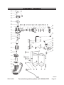
1
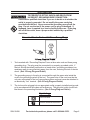
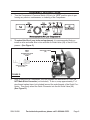
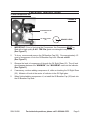
AIR COMPRESSOR
2 HP - TWIN TANK - 4 GALLON
95498
Set up and Operating Instructions
CAUTION!
Your Warranty Is Voided If:
A. You do not put compressor oil in the Compressor’s crankcase prior to its first use.
Before each use, check the oil level. Never run the Compressor with low or no compressor oil. Running the Compressor with low or no oil will permanently damage the unit.
B. You drop the Air Compressor.
Always lift the Air Compressor using its Handle.
Visit our website at: http://www.harborfreight.com
Read this material before using this product.
Failure to do so can result in serious injury.
Save this manual.
Copyright© 2007 by Harbor Freight Tools®. All rights reserved. No portion of this manual or any artwork
contained herein may be reproduced in any shape or form without the express written consent of
Harbor Freight Tools. Diagrams within this manual may not be drawn proportionally. Due to continuing
improvements, actual product may differ slightly from the product described herein. Tools required for
assembly and service may not be included.
For technical questions or replacement parts, please call 1-800-444-3353.
Cover revised 08k, 09j
PRODUCT SPECIFICATIONS
Electrical Requirements
Maximum Air Pressure
Air Flow Capacity
Auto Turn On/Shut Off
Air Tank Capacity
Air Outlet Size
Recommended Oil Type
120 V~ / 60 Hz / 16 A / 2 HP Motor / 3400 RPM
115 PSI
5.8 Cubic Feet Per Minute (CFM) @ 40 PSI
4.4 Cubic Feet Per Minute (CFM) @ 90 PSI
Pressure On @ 85 PSI / Pressure Off @ 115 PSI
4 Gallons Total
1/4”-18 NPT Male Threads
SAE 15W-30W Non-Detergent Compressor Oil
SAVE THIS MANUAL
You will need this manual for the safety warnings and precautions, assembly,
operating, inspection, maintenance and cleaning procedures, parts list and assembly
diagram. Keep your invoice with this manual. Write the invoice number on the inside
of the front cover. Keep this manual and invoice in a safe and dry place for future reference.
GENERAL SAFETY RULES AND PRECAUTIONS
WARNING!
READ AND UNDERSTAND ALL INSTRUCTIONS
Failure to follow all instructions listed below may result in
electric shock, fire, and/or serious injury.
SAVE THESE INSTRUCTIONS
WORK AREA
1.
Keep your work area clean and well lit. Cluttered benches and dark areas invite
accidents.
Do not operate air tools in explosive atmospheres, such as in the
presence of flammable liquids, gases, or dust. Power tools create
sparks which may ignite the dust or fumes.
2.
3.
Keep bystanders, children, and visitors away while operating a power tool.
Distractions can cause you to lose control. Protect others in the work area from
debris such as chips and sparks. Provide barriers or shields as needed. Children
should not be allowed in the work area.
PERSONAL SAFETY
1.
Stay alert. Watch what you are doing, and use common sense when operating a power tool. Do not use a power tool while tired or under the influence
of drugs, alcohol, or medication. A moment of inattention while operating power
tools may result in serious personal injury.
REV 07b;07h; 09c; 09g
SKU 95498
For technical questions, please call 1-800-444-3353.
Page 2
2.
Dress properly. Do not wear loose clothing or jewelry. Contain long hair.
Keep your hair, clothing, and gloves away from moving parts. Loose clothes,
jewelry, or long hair can be caught in moving parts.
3.
Avoid accidental starting. Be sure the Compressor Control Knob (83) is in
its “OFF” position before moving the Compressor and before performing any
service, maintenance, or cleaning procedures on the unit.
4.
Remove adjusting keys or wrenches before turning the Compressor on. A
wrench or a key that is left attached to a rotating part of the machine may result in
personal injury.
5.
Do not overreach. Keep proper footing and balance at all times. Proper footing and balance enables better control of the power tool in unexpected situations.
Use safety equipment. Always wear eye protection. Always wear
ANSI-approved safety impact glasses and full face shield when using
this product. ANSI-approved hearing protection must also be used.
6.
TOOL USE AND CARE
1.
Do not force the tool. Use the correct tool for your application. The correct
tool will do the job better and safer at the rate for which it is designed.
2.
Do not use the Compressor if the Compressor’s Pressure Switch (64) does
not turn it on or off. Any tool that cannot be controlled with its Pressure Switch is
dangerous and must be replaced.
3.
Store idle tools out of reach of children and other untrained persons. Tools
are dangerous in the hands of untrained users.
4.
Maintain tools with care. Properly maintained tools are less likely to bind and are
easier to control. Do not use a damaged tool. Tag damaged tools “Do not use”
until repaired.
5.
Check for misalignment or binding of moving parts, breakage of parts, and
any other condition that may affect the tool’s operation. If damaged, have
the tool serviced before using. Many accidents are caused by poorly maintained
tools.
6.
Use only accessories that are recommended by the manufacturer for your
model. Accessories that may be suitable for one tool may become hazardous
when used on another tool.
SERVICE
1.
Tool service must be performed only by qualified repair personnel. Service or
maintenance performed by unqualified personnel could result in a risk of injury.
SKU 95498
For technical questions, please call 1-800-444-3353.
Page 3
2.
When servicing a tool, use only identical replacement parts. Follow instructions in the “Inspection, Maintenance, And Cleaning” section of this manual.
Use of unauthorized parts or failure to follow maintenance instructions may create
a risk of electric shock or injury.
SAVE THESE INSTRUCTIONS
SPECIFIC SAFETY RULES AND PRECAUTIONS
1.
Your Warranty is voided if:
a.You do not put compressor oil in the Compressor’s crankcase prior to its
first use. Before each use, check the oil level. Never run the Compressor with
low or no compressor oil. Running the Compressor with low or no oil will permanently damage the unit.
b.You drop the Air Compressor. Always lift the Air Compressor using its Handle.
2.
Maintain labels and nameplates on the Air Compressor. These carry important
information. If unreadable or missing, contact Harbor Freight Tools for a replacement.
3.
This Air Compressor is NOT equipped and should not be used “as-is” to supply
breathing quality air. For any application of air for human consumption, you must
fit the Air Compressor with suitable in-line safety and alarm equipment (not included). This additional equipment is necessary to properly filter and purify the air
to meet minimal specifications for Grade D breathing as described in Compressed
Gas Association Commodity Specification G 7.1-1966, OSHA 29 CFR 1910. 134,
and/or Canadian Standards Associations (CSA). In the event the Air Compressor is used for the purpose of breathing air application and proper in-line safety
and alarm equipment is not simultaneously used, existing warranties are void, and
Harbor Freight Tools disclaims any liability whatsoever for any loss, personal injury,
or damage.
4.
Never attempt to repair or modify the Air Tanks (51). Welding, drilling, or any other
modification will weaken the Tanks resulting in damage from rupture or explosion.
Always replace worn, cracked, or damaged Tanks.
5.
Never use plastic (PVC) pipe for compressed air. Serious injury or death could
result. Any tube, pipe, or hose used must have a pressure rating higher than 150
PSI. Minimum recommended pipe size: Up to 50 feet long use 1/2” diameter.
Greater than 50 feet use 3/4” diameter. Larger diameter pipe is always better.
6.
Make sure all tools and equipment used with the Air Compressor are rated to
the appropriate capacity. Do not use any tool or equipment that does not operate from 85 PSI to 115 PSI.
7.
Drain the Air Compressor every day. Do not allow excessive moisture to build
up inside the Air Compressor’s Tanks. Do not open the Drain Valves (52) with
SKU 95498
For technical questions, please call 1-800-444-3353.
Page 4
more than 10 PSI of air pressure in the Tanks. Do not unscrew the Drain Valves so
that more than four threads are showing.
8.
Avoid injury. Never direct the Air Outlet Valve (68) at people or animals.
9.
Do not alter or remove the Safety Release Valve (62).
10. Make sure the Air Compressor is located on a flat, level, sturdy surface capable of supporting the weight of the Compressor, operator(s), and any additional tools and equipment.
11. Industrial applications must follow OSHA guidelines.
12. Never stand on the Air Compressor. Serious injury could result if the Compressor is tipped.
13. Never leave the Air Compressor unattended when it is plugged in and running. Turn off the Compressor, and unplug the unit before leaving.
14. Do not allow children and other unauthorized people to handle or play with
the Air Compressor.
15. Do not move or transport the Compressor if the Air Tanks (51) are under
pressure.
16. Do not force the Compressor. This tool will do the work better and safer at the
speed and capacity for which it was designed.
17. Avoid body contact with oils and lubricants used in the Compressor. If swallowed, seek medical treatment immediately. For skin contact, immediately wash
with soap and water. For eye contact, immediately flush eyes with clean water.
18. Prolonged exposure to noise levels above 85 dBA is hazardous to hearing.
Always wear hearing protection when operating or working around the Compressor
when it is running.
19. WARNING: The brass components of this product contain lead, a chemical known
to the State of California to cause birth defects (or other reproductive harm).
(California Health & Safety code § 25249.5, et seq.)
20. People with pacemakers should consult their physician(s) before use. Electromagnetic fields in close proximity to heart pacemaker could cause pacemaker interference or pacemaker failure.
21. WARNING! The warnings and precautions discussed in this manual cannot cover
all possible conditions and situations that may occur. It must be understood by the
operator that common sense and caution are factors which cannot be built into this
product, but must be supplied by the operator.
SAVE THESE INSTRUCTIONS
SKU 95498
For technical questions, please call 1-800-444-3353.
Page 5
Grounding
To prevent electric shock and death from
incorrect grounding wire connection:
Check with a qualified electrician if you are in doubt as to whether the
outlet is properly grounded. Do not modify the power cord plug
provided with the tool. Never remove the grounding prong from the
plug. Do not use the tool if the power cord or plug is damaged. If
damaged, have it repaired by a service facility before use. If the plug
will not fit the outlet, have a proper outlet installed by a qualified
electrician.
Grounded Tools: Tools with Three Prong Plugs
1.
Tools marked with “Grounding Required” have a three wire cord and three prong
grounding plug. The plug must be connected to a properly grounded outlet. If
the tool should electrically malfunction or break down, grounding provides a low
resistance path to carry electricity away from the user, reducing the risk of electric
shock. (See 3-Prong Plug and Outlet.)
2.
The grounding prong in the plug is connected through the green wire inside the
cord to the grounding system in the tool. The green wire in the cord must be the
only wire connected to the tool’s grounding system and must never be attached to
an electrically “live” terminal. (See 3-Prong Plug and Outlet.)
3.
The tool must be plugged into an appropriate outlet, properly installed and grounded in accordance with all codes and ordinances. The plug and outlet should look
like those in the preceding illustration. (See 3-Prong Plug and Outlet.)
Symbology
Double Insulated
Canadian Standards Association
SKU 95498
For technical questions, please call 1-800-444-3353.
Page 6
Symbology
Underwriters Laboratories, Inc.
V~
A
Volts Alternating Current
Amperes
No Load Revolutions per Minute
n0 xxxx/min. (RPM)
UNPACKING
When unpacking, check to make sure all the parts shown on the Parts List on
page 13 are included. If any parts are missing or broken, please call Harbor Freight
Tools at the number shown on the cover of this manual as soon as possible.
SKU 95498
For technical questions, please call 1-800-444-3353.
Page 7
ASSEMBLY INSTRUCTIONS
1.
Turn the Compressor’s Pressure Switch (64) is in its “OFF” position prior to performing any service, maintenance, or cleaning of the Compressor.
2.
To extend the life of your tools and equipment, it is recommended that you
install an oiler and water filter in-line with the Air Outlet Valve (68) of the Air Compressor. (See Figure C.)
WRAP
WITH
PIPE SEALANT TAPE
AIR OUTLET VALVE
(68)
(NOT INCLUDED)
HERE
QUICK CONNECTOR
(NOT INCLUDED)
FIGURE D
3.
Prior to using the Air Compressor, the unit requires the attachment of a 1/4”-18
NPT Male Quick Connector (not included). To do so, wrap approximately 3” of
pipe thread sealant tape (not included) around the male threads of the Quick Connector. Then firmly screw the Quick Connector into the Air Outlet Valve (68).
(See Figure D.)
SKU 95498
For technical questions, please call 1-800-444-3353.
Page 8
PRE-START INSTRUCTIONS
To Add Compressor Oil:
FIGURE E
OIL BREATHER CAP
(25)
OIL SIGHT GLASS
(22)
DESIRED LEVEL
1.
IMPORTANT! Prior to first using the Compressor, the Compressor MUST be filled with a high quality S.A.E. 15W-30w grade non-detergent compressor oil.
(See Figure E.)
2.
To do so, unscrew and remove the Oil Breather Cap (25). Pour approximately 1/2
quart of compressor oil into the Oil Breather Cap hole. Do not overfill.
(See Figure E.)
3.
Observe the level of compressor oil through the Oil Sight Glass (22). The oil level
should appear between the “MINIMUM” and “MAXIMUM” marks on the Indicator.
(See Figure E.)
4.
If necessary, continue adding compressor oil, while re-checking the Oil Sight Glass
(22). Maintain oil level at the center of indicator in the Oil Sight glass.
5.
When finished adding compressor oil, re-install the Oil Breather Cap (25) back into
the Oil Breather Cap hole.
SKU 95498
For technical questions, please call 1-800-444-3353.
Page 9
OPERATING INSTRUCTIONS
To Start The Compressor:
REGULATOR
(67)
PRESSURE SWITCH
(64)
AIR
OUTLET
VALVE
(68)
AIR HOSE
(NOT INCLUDED)
TANK DRAIN VALVE
(52)
TOOL
PRESSURE
GAUGE
(66)
TANK
PRESSURE
GAUGE
(63)
SAFETY
RELEASE
VALVE
(62)
FIGURE F
1.
Check to make sure the Air Tank’s Drain Valve (52), located on the bottom Air Tank
(51), is fully closed.
2.
Turn the Air Outlet Valve (68) to its closed position.
3.
Connect an air hose (not included) to the previously installed Quick Connector.
Then, connect the other end of the air hose to the pneumatic tool (not included).
4.
Plug the Power Cord (55) into the nearest 120 volt, grounded, electrical outlet.
5.
Pull up on the Pressure Switch (64) to its “START” position to turn on the unit.
6.
When the Tank Pressure Gauge (63) reaches at least 85 PSI, turn the Air Outlet
Valve to its open position to allow air to the pneumatic tool.
7.
Once the air pressure reaches the pneumatic tool, observe the Tool Pressure
Gauge (66). Adjust the Regulator (67) to feed the proper PSI to the tool. To do so,
turn the Regulator clockwise to increase the PSI. Turn the Regulator counterclockwise to decrease the PSI.
Note: When the maximum air pressure, 115 PSI, is reached as indicated by the Tank
Pressure Gauge (63), the motor will stop. The Compressor will automatically restart when the air pressure drops below 85 PSI.
IMPORTANT: To decompress the air pressure in the Air Tanks (51), push down on the
Pressure Switch (64) to its “STOP” position. Then, pull out on the Safety Release
Valve to immediately release air pressure from the Air Tanks.
SKU 95498
For technical questions, please call 1-800-444-3353.
Page 10
To Stop The Compressor:
1.
Push down on the Pressure Switch (64) to its “STOP” position.
2.
Unplug the Air Compressor from its electrical outlet.
3.
Turn the Air Outlet Valve (68) to its closed position. (See Figure F.)
4.
Squeeze the trigger on the pneumatic tool to release any remaining air pressure
from the tool. Then disconnect the air hose from the tool, and store the tool in a
clean, dry, safe location out of reach of children.
5.
Disconnect the other end of the air hose from the Compressor’s Air Outlet Valve
(68), and store the air hose in a clean, dry, safe location out of reach of children.
6.
Pull out on the Safety Release Valve (62) to release all remaining air pressure from
the Air Tanks (51). (See Figure F.)
7.
Remove any moisture in the Air Tanks (51) by opening the Tank Drain Valve (52).
Then, retighten the Drain Valve. (See Figure F.)
8.
Allow the Air Compressor to completely cool. Then store the unit in a clean, dry,
safe location out of reach of children.
SKU 95498
For technical questions, please call 1-800-444-3353.
Page 11
INSPECTION, MAINTENANCE, AND CLEANING
Procedures not specifically explained in this manual must be performed
only by a qualified technician.
To prevent serious injury from accidental
operation:
Turn the Power Switch of the tool to its “OFF” position and unplug the
tool from its electrical outlet before performing any inspection,
maintenance, or cleaning procedures.
1.
Before each use, inspect the general condition of the Air Compressor. Check for
loose screws, misalignment or binding of moving parts, cracked or broken parts,
damaged electrical wiring, loose air fittings, and any other condition that may affect
the safe operation of the Compressor. If abnormal noise or vibration occurs, have
the problem corrected before further use. Do not use damaged equipment.
2.
Before each use, check the compressor oil level in the Oil Sight Glass (22). If
necessary, fill the crankcase of the Air Compressor with the proper amount and
type of compressor oil.
3.
Daily, purge the Air Tanks (51) of all air and moisture to prevent corrosion. To do
so, slowly and carefully unscrew (no more than four threads) the Tank Drain Valve
(52) until the compressed air and condensation begins to be released from the
Tanks. Allow sufficient time for all of the air and condensation to escape from the
Tanks. Then, firmly re-tighten the Drain Valve.
TROUBLESHOOTING
Problem
Compressor will not
start.
Low pressure.
Possible Cause
1. Blown fuse or circuit
breaker tripped.
2. Loose electrical
connections.
3. Bad capacitors.
1. Restricted air filter.
2. Defective check valve.
3. Air leak in safety valve.
Safety valve releasing.
SKU 95498
4. Defective valve plate.
1. Defective pressure
switch.
2. Defective safety valve.
Possible Solution
1. Replace or reset fuse/circuit breaker.
2. Plug Compressor into a working, 120 volt,
grounded, electrical outlet.
3. Replace capacitors.
1. Replace air filter.
2. Have a qualified service technician replace
check valve.
3. Check valve by pulling on ring. If condition
persists, have a qualified service technician
replace valve.
4. Replace valve plate.
1. Have a qualified service technician replace
pressure switch.
2. Replace safety valve.
For technical questions, please call 1-800-444-3353.
Page 12
Problem
Possible Cause
Oil discharge in air.
1. Too much oil in
crankcase.
2. Compressor overheated.
3. Restricted oil breather
cap.
Pressure switch will not Defective pressure switch.
turn off Compressor.
Possible Solution
1. Drain crankcase and refill to proper level on
sight glass.
2. Reduce air pressure regulation.
3. Clean or replace oil breather cap.
Immediately unplug Compressor from its
electrical outlet. Do not operate Compressor
until a qualified service technician can replace
pressure switch.
PLEASE READ THE FOLLOWING CAREFULLY
The manufacturer and/or distributor has provided the parts list and assembly
diagram in this manual as a reference tool only. Neither the manufacturer or
distributor makes any representation or warranty of any kind to the buyer that
he or she is qualified to make any repairs to the product, or that he or she is
qualified to replace any parts of the product. In fact, the manufacturer and/
or distributor expressly states that all repairs and parts replacements should
be undertaken by certified and licensed technicians, and not by the buyer. The
buyer assumes all risk and liability arising out of his or her repairs to the
original product or replacement parts thereto, or arising out of his or her
installation of replacement parts thereto.
PARTS LIST
Part
1
2
3
4
5
6
7
8
9
10
11
13
14
15
16
17
18
19
20
21
22
23
Description
Plastic Housing
Spring Washer
Washer
Screw (M5 x 14)
Fan
Screw (5 x 115)
Rear Cap
Washer
Bearing (6202)
Stator
Rotor
Running Capacitor
Bearing (6204)
Oil Seal
Nut (M8)
Crankcase
Crankshaft
Screw (M8 x 16 – Left hand)
Gasket
Crankcase Cover
Oil Sight Glass
Drain Plug
Part
24
25
26
27
28
29
30
31
32
33
34
35
36
37
38
39
40
41
42
43
44
45
Description
Pan Head Screw
Oil Breather Cap
Spring Washer (#8)
Washer (#8)
Screw (M8 x 20)
Connecting Rod
Piston
Spring Washer
Piston Pin
Cylinder Gasket
Cylinder
Spring Washer (#6)
Washer (#6)
Screw (M6 x 40)
Gasket
Sealer Ring
Valve Gasket
Valve Plate Assy.
Air Intake Valve
Limit Pin
Cylinder Gasket
Air Filter
Part
46
47
48
49
50
51
52
53
54
55
56
61
62
63
64
65
66
67
68
79
Description
Cylinder Head
Elbow Exhaust
Exhaust Pipe
Check Valve
Unload Pipe
Air Tank
Tank Drain Valve
Rubber Foot
Screw (M6 x 20)/Nut (M6)
Power Cord
Rubber Gasket
Rubber Grip
Safety Release Valve
Tank Pressure Gauge
Pressure Switch
Connector
Tool Pressure Gauge
Regulator
Air Outlet Valve
Frame Assy.
Note: Some parts are listed and shown for illustration purposes only, and are not available individually as replacement parts.
REV 08k
SKU 95498
For technical questions, please call 1-800-444-3353.
Page 13
ASSEMBLY DIAGRAM
23 22 21
20
45
44
43
42
41
40
39
38
37
36
35
34
33
32
31
30
29
28
27
26
19
18
46
17
47
11
10
49 50
68 67 66 65 62 64
13
48 79 56
16 15 14
63
79
9
8
7
6
5
4 3 2
61
51
52
54
53
55
1
Page 14
For technical questions, please call 1-800-444-3353.
SKU 95498
25
24
REV 08k
Limited 1 year / 90 day Warranty
Harbor Freight Tools Co. makes every effort to assure that its products meet high
quality and durability standards, and warrants to the original purchaser that for a period
of one year from date of purchase that the tank is free of defects in materials and workmanship (90 days if used by a professional contractor or if used as rental equipment).
Harbor Freight Tools also warrants to the original purchaser, for a period of ninety days
from date of purchase, that all other parts and components of the product are free from
defects in materials and workmanship. This warranty does not apply to damage due directly or indirectly to misuse, abuse, negligence or accidents, repairs or alterations outside our facilities, normal wear and tear, or to lack of maintenance. We shall in no event
be liable for death, injuries to persons or property, or for incidental, contingent, special
or consequential damages arising from the use of our product. Some states do not allow
the exclusion or limitation of incidental or consequential damages, so the above limitation of exclusion may not apply to you. This warranty is expressly in lieu of
all other warranties, express or implied, including the warranties
of merchantability and fitness.
To take advantage of this warranty, the product or part must be returned to us with
transportation charges prepaid. Proof of purchase date and an explanation of the complaint must accompany the merchandise. If our inspection verifies the defect, we will either repair or replace the product at our election or we may elect to refund the purchase
price if we cannot readily and quickly provide you with a replacement. We will return repaired products at our expense, but if we determine there is no defect, or that the defect
resulted from causes not within the scope of our warranty, then you must bear the cost
of returning the product.
This warranty gives you specific legal rights and you may also have other rights
which vary from state to state.
3491 Mission Oaks Blvd. • PO Box 6009 • Camarillo, CA 93011 • (800) 444-3353
SKU 95498
For technical questions, please call 1-800-444-3353.
Page 15