1
FCC COMPLIANCE STATEMENT
FOR AMERICAN USERS
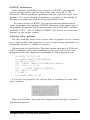
This equipment generates and uses radio frequency energy and if not installed and used properly, that is, in strict accordance with the manufacturer’s instructions, may cause interference
to radio and television reception. It has been type tested and found to comply with the limits
for a Class B computing device in accordance with the specifications in Subpart J of part 15 of
FCC Rules, which are designed to provide reasonable protection against such interference in a
residential installation. However, there is no guarantee that interference will not occur in a
particular installation. If this equipment does cause interference to radio or television reception, which can be determined by turning the equipment off and on, the user is encouraged to
try to correct the interference by one or more of the following measures:
— Reorient the receiving antenna
— Relocate the printer with respect to the receiver
— Plug the printer into a different outlet so that the printer and receiver are on different
branch circuits.
If necessary, the user should consult the dealer or an experienced radio/television technician
for additional suggestions. The user may find the following booklet prepared by the Federal
Communications Commission helpful:
“How to Identify and Resolve Radio-TV Interference Problems.”
This booklet is available from the U.S. Government Printing Office, Washington, DC 20402.
Stock No. 004-000-0345-4.
WARNING
The connection of a non-shielded printer interface cable to this printer will invalidate the FCC
Certification of this device and may cause interference levels which exceed the limits established by the FCC for this equipment. If this equipment has more than one interface connector, do not leave cables connected to unused interfaces.
All rights reserved. No part of this publication may be reproduced, stored in a retrieval system, or
transmitted, in any form or by any means, mechanical, photocopying, recording or otherwise,
without the prior written permission of Seiko Epson Corporation. No patent liability is assumed
with respect to the use of the information contained herein. While every precaution has been taken
in the preparation of this book, Seiko Epson Corporation assumes no responsibility for errors or
omissions. Neither is any liability assumed for damages resulting from the use of the information
contained herein.
Graphics created with UniPaint by Unison World Inc. and EPSON 3D-Graph.
Apple is a registered trademark of Apple Computer, Inc.
Centronics is a registered trademark of Centronics Data Computer Corporation.
Epson is a registered trademark of Seiko Epson Corporation.
IBM is a registered trademark of International Business Machines Corporation.
Microsoft is a trademark of Microsoft Corporation.
ESC/P is a registered trademark of Seiko Epson Corporation.
Copyright © 1986 by Seiko Epson Corporation
Nagano, Japan
ii
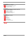
Contents
Introduction
2
About This Manual
Chapter 1
Setting Up Your FX Printer
1-1 Unpacking Your Printer
1-2 Selecting the Right Location
1-3 Installing the Ribbon
1-6 Loading Continuous-feed Paper
1-12 Turning On the Printer
1-12 Operating the Control Panel
1-14 SelecType
1-16 Running the Self Test
1-17 Connecting the Printer to Your Computer
1-18 Choosing the Operating Mode with DIP Switches
Chapter 2
Choosing and Loading Paper
2-1 Choosing Paper
2-1 Using Single-sheet Paper
2-6 Reinstalling the Tractor Unit
2-8 The Paper Thickness Lever
Chapter 3
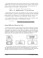
Using the FX with Application Programs
3-1
3-2
3-3
3-4
3-6
3-6
Printer Selection Menus
Computer -Printer Communication
Word Processors
Spreadsheets
Graphics Programs
Programming Languages
Contents
iii
Chapter 4
FX Printer Features
4-1 Quality and Fonts
4-2 Print Size and Character Width
4-2 Pitches and Proportional Spacing
4-3 Special Effects and Emphasis
4-4 Using Different Character Sets
4-5 Page Layout and Other Commands
Chapter 5
Graphics and User-defined Characters
5-2 The Print Head
5-3 Pin Labels
5-4 Graphics Commands
5-6 Simple Graphics Programming
5-8 Density Varieties
5-10 Designing Your Own Graphics
5-13 User-defined Characters
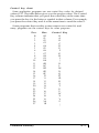
Appendix A
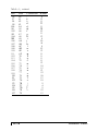
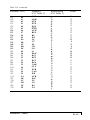
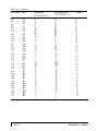
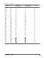
Command Summary
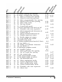
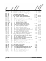
A-4 Commands in Numerical Order
A-7 Epson (ESC/P) Commands
A-36 IBM Printer Emulation Mode Commands
Appendix B
Character Tables
El Epson Mode
B-9 Epson International Character Sets
B-11 IBM Printer Emulation Mode
Appendix C
Problem Solving and Maintenance
C-1
C-3
C-3
C-4
C-5
C-7
iv
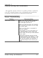
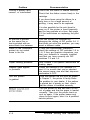
General Troubleshooting
Troubleshooting Graphics Problems
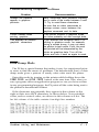
Data Dump Mode
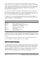
IBM PC BASIC Solutions
Maintaining Your Printer
Transporting the Printer
Contents
Appendix D
Defaults and DIP Switches
D-1 Default and Initialization Settings
D-2 DIP Switch Settings
D-3 International Character Sets
Appendix E
Choosing and Setting Up Optional Interfaces
E-1
E-2
E-3
E-6
E-7
Compatible Interfaces
Choosing an Interface
Installing an Interface
Inserting the Interface board
Serial Interface Settings
Appendix F
Technical Specifications
F-1
F-1
F-2
F-2
F-3
F-3
F-5
Printing
Paper
Mechanical
Electrical
Environment
Parallel Interface
Data Transfer Sequence
Index
Contents
v
Introduction
The FX-86e and FX-286e printers combine all the well-known virtues
of previous Epson 9-pin printers with many features normally exclusive
to costly 24-pin printers.
l
The speed of draft printing is 240 characters per second in draft elite
and 200 in draft pica. When you have perfected a document, you
can switch to one of two Near Letter Quality fonts-Roman or
Sans Serif.
Draft printing is extremely fast.
NLQ Roman is clear and typewriter-like.
NLQ Sans Serif is crisp and distinctive.
l
l
l
l
The SelecType feature gives you access to Near Letter Quality
(NLQ) and condensed print. All you have to do is press the button
for the style you want. While the FX is printing, the SelecType panel
shows you what choices it’s using.
If you are using software designed for an IBM@ printer, you have the
choice of using the FX in Epson mode or IBM printer emulation
mode. Even better, you can combine the best of both worlds; the
powerful Epson mode commands can now print character graphics
like those used by IBM printers and computers.
Loading paper is now easier than ever. Single sheets can be loaded
by just moving a lever, and the tractor lets you load a wide range of
widths of continuous-feed paper, including labels.
For headings and other emphasis, you can use double-high and
double-wide printing.
Introduction
1
About this Manual
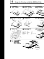
To make it easier to set up your new FX-86e or FX-286e, this manual
includes a lo-step guide. This guide, which is printed on the inside of
the back flap, summarizes the first chapter’s setting up instructions.
Chapters 2 through 5 cover the basic and advanced functions, and
the appendixes contain reference information, including all the details
you need to use any of the printer’s commands, and some advice on
solving problems.
Finally, there is a comprehensive index, and inside the back of the
manual is a pull-out quick reference card containing the information
you need most.
2
Introduction
Chapter 1
Setting Up Your FX Printer
Setting up your new FX is easy. Simply follow the steps in this
chapter.
Note
The FX-86e and FX-286e are basically the same printer except that the
FX-286e can accept wider paper. Therefore, the illustrations in this
manual show only the FX-86e.
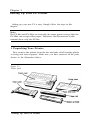
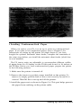
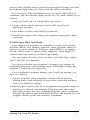
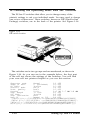
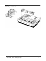
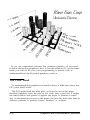
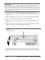
1 Unpacking Your Printer
First, remove the printer from the box and take off all outside plastic
covering and foam supports. Make sure you have received all the parts
shown in the illustration below.
Figure 1-1
Printer parts
Setting Up Your FX Printer
1-1
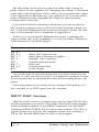
Tilt the tractor cover up and remove the two foam pads underneath
it. (These pads protect the tractor unit during shipping; be sure to save
them.)
WARNING
The printer is protected by a print head protector, a platen
protector and two locking tabs during shipping. These protective
items must be removed before you turn on the printer. Follow the
steps below Figure 1-2.
Also, you should install the paper feed knob. To install the knob,
simply push it onto the shaft on the right side of the printer as
shown in Figure 1-2.
1. Remove the left locking tab.
2. Remove the print head protector.
3. Move the print head to the left.
4. Remove the right locking tab and the platen protector.
2 Selecting the Right Location
The most important consideration in choosing a location for your
printer is that it be close enough to connect a cable to your computer.
But also keep the following tips in mind:
1-2
Setting Up Your FX Printer
l
l
l
l
l
l
Place the printer or printer stand on a solid and level foundation.
Avoid setting it on carpet or on unstable surfaces such as chairs.
Use a grounded outlet-one that has three holes to match the power
plug on the printer. Don’t use an adapter plug.
Avoid using electrical outlets that are controlled by wall switches. If
you accidentally turn off a switch, you could wipe out valuable
information and stop your printing.
Keep your printer and computer away from base units for cordless
telephones.
Avoid using an outlet on the same circuit breaker with large
electrical machines or appliances that might disrupt the flow of
power to your printer.
Choose a place that is clean and away from moisture, dust, and
excessive heat (such as a heater or direct sunlight).
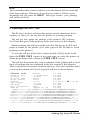
If you are going to use continuous-feed paper, clear enough space
around the printer so that the paper has an unobstructed path in and
out of the printer. There are three common methods of arranging a
printer and continuous paper:
l
l
l
Using a printer stand with the paper stacked underneath it.
Using a desk or table as a stand, with the printer near the rear edge
and the paper on the floor or on a shelf.
Putting the printer on a desk or table and stacking the paper behind
the printer.
3 Installing the Ribbon
To install the ribbon, follow the directions below:
1. Remove the tractor cover that comes installed on the printer. To
remove it, simply pull the back of the cover toward you until the
cover is vertical. Then lift it up and off the printer.
2. Manually move the print head to the middle of the platen.
Setting Up Your FX Printer
1-3
WARNING
The power must be OFF when you move the print head. Moving the
print head when the power is ON may damage your printer. If you’ve
been using your printer just before changing the ribbon cartridge, be
careful not to touch the print head because it becomes hot during use.
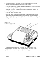
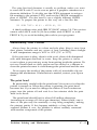
3. before installing the ribbon cartridge, turn the small knob on top in
the direction of the arrow to tighten the ribbon as shown in Figure 1-3.
Figure 1-3
Tightening the ribbon
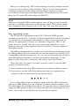
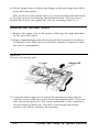
4. For the FX-86e, hold the ribbon cartridge by the raised plastic fin
on top of the cartridge; for the FX-286e hold the cartridge by the
two plastic tabs. Lower the cartridge into the printer, guiding the
two pins on each end of the cartridge into the slots in the printer
frame, as shown in Figure 1-4. Press firmly on each end of the
cartridge to make sure the pins are firmly seated in the slots.
5. Now use the point of a pencil to guide the ribbon into place between the ribbon guide and the print head as shown in Figure 1-5.
(There is also a diagram on the top of the ribbon cartridge itself.)
6. With the cartridge in place, again turn the ribbon knob in the
direction of the arrow to tighten the ribbon.
And that’s it-the ribbon is now installed.
1-4
Setting Up Your FX Printer
Figure 1-4.
Installing the ribbon cartridge
Figure 1-5.
Positioning the ribbon
Setting Up Your FX Printer
1-5
4 Loading Continuous-feed Paper
When you receive your FX, it is set up to print on continuous-feed
paper. If you plan to use single-sheet paper, turn to Chapter 2 for
instructions on setting up the printer for single sheets. If you have
bought the optional automatic sheet feeder, complete the remainder of
the setup steps before you install the automatic sheet feeder (which has
its own manual).
The FX tractor units are adjustable to accommodate different widths
of paper-from 4 to 10 inches on the FX-86e and from 4 to 16 inches on
the FX-286e. Before you load continuous-feed paper, prepare the printer
in the following manner:
1. Make sure the printer is turned off.
2. Remove the tractor cover that comes installed on the printer. To
remove it, simply pull the back of the cover toward you until it is
vertical. Then lift the cover up and off the printer.
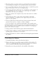
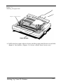
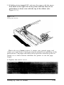
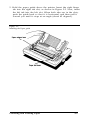
3. Install the paper rest as shown in Figure 1-6. This part helps prevent
the paper from catching on the printer cable.
1-6
Setting Up Your FX Printer
Figure 1-6.
Installing the paper rest
4. Pull both the paper release lever and the paper bail lever toward the
front of the printer. (Figure 1-6 shows where these levers are.)
Setting Up Your FX Printer
1-7
Now you are ready to load the continuous-feed paper. Just follow the
steps below:
1. Using Figure 1-7 as a guide, pull the locking levers on the
pin-feed holders forward so that you can move the holders to
the left and right.
Figure 1-7.
Pin-feed locking levers
2. Move the left holder so that the locking lever is about 1/4 inch
from the left side and push the locking lever back to lock that
holder in place. Leave the right holder unlocked.
3. Open the pin-feed covers as shown in Figure 1-8.
WARNING
Do not use the pin-feed covers to move the pin-feed holders.
1-8
Setting Up Your FX Printer
Figure 1-8.
Open pin-feed cover
4. Guide the paper into the paper slot, and push it through until it
comes up between the ribbon guide and the platen. (Moving the
paper with a side-to-side motion makes it easier to push the paper
through.)
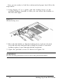
5. Pull the paper up until the top is above the pin-feed holders. Fit the
holes on the left side of the paper over the pins in the left holder (as
shown in Figure 1-9) and close the cover.
Figure 1-9.
Fitting the paper over the pin feeds
Setting Up Your FX Printer
1-9
6. Fit the right side of the paper into the right holder, moving the
holder as needed to match the width of the paper.
7. Close the right cover, making sure the paper has no dips or wrinkles
and lock the right holder in place.
Now that you have loaded the continuous-feed paper, prepare the
printer for printing.
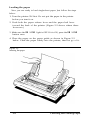
1. Push the paper bail lever back.
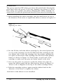
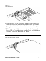
2. Hold the paper guide above the printer with the edge tab on the
left. Insert the right hinge tab into the right tab slot, as shown in
Figure 1-10. Then insert the left tab into the left slot and push
the guide back so that it is horizontal.
Figure 1-10
This guide keeps paper that is coming out of the printer from
interfering with the paper going in. The guide is also used in the
upright position for printing on single sheets of paper.
1-10
Setting Up Your FX Printer
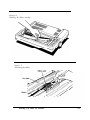
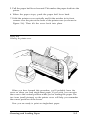
3. With the printer turned OFF, advance the paper with the paper
feed knob on the right side of the printer until the first row of
perforations is about even with the top of the ribbon. (See
Figure 1-1 1.)
Figure 1-11.
Setting top of form
This is the top of form position. It makes your printed pages end
where you want them to and prevents the printer from printing on the
perforations. The paper should be in this position when the power is
turned on or when software initializes the printer or sets the page
length.
4. Replace the tractor cover.
Setting Up Your FX Printer
1-11
5 Turning On the Printer
Before plugging in the power cord, see that the power switch near
the back of the left side of the printer is turned off; then plug the
power cord into a properly grounded socket.
WARNING
Before turning on the printer, be absolutely sure you have removed all
packing materials. Turning on the printer when the print head cannot
move may seriously damage the mechanism.
Now, turn the power ON with the switch on the left side of the
printer. When you turn on the printer, three things happen:
l
l
l
The print head moves back and forth and stops at the left side of the
printer; this is the home position.
The printer is initialized and set to certain default settings (which are
fully described in Appendix D).
The green power light on the control panel comes on.
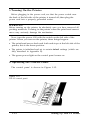
6 Operating the Control Panel
The control pane! is shown in Figure 1-12.
Figure 1-12.
The FX control panel.
1.12
Setting Up Your FX Printer
The three buttons nearest the front of the printer control advancing
the paper and communication with the computer. The four indicator
lights show when the printer is turned on and when it is ready to use.
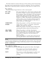
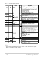
The buttons
There are three large buttons on the control panel.
OFF LINE/
ON LINE
The green light next to this button indicates that
the printer is able to receive and print data from
the computer. When the light is off, the printer is
off line and cannot receive any data. Press the
button to change from on line to off line or from
off line to on line. The printer automatically goes
off line when you try to print without paper in
the printer. Pressing the button then has no
effect until you load paper.
FORM FEED/
ROMAN
When the printer is off line, this button ejects a
single sheet of paper or advances continuous
paper to the next top of form.
When the printer is on line and in NLQ mode,
pressing the button selects the Roman font.
LINE FEED/
SANS SERIF
When the printer is off line, this button
advances the paper one line each time you press
it or continuously if you hold it down. When
the printer is turned on, use this button to
advance paper.
When the printer is on line and in NLQ mode,
pressing the button selects the Sans Serif font.
Note
Use the paper feed knob on the right side of the printer only when the
printer is turned OFF Using it when the printer is on can damage the
printer mechanism.
The indicator lights
In addition to the ON LINE light, the printer has three other lights.
POWER
This comes on to show that the printer is
connected to the power and is turned on.
READY
This comes on when the printer is on line and
ready to print. It normally flickers during
printing.
Setting Up Your FX Printer
1-13
PAPER OUT
This comes on when the printer is out of paper.
Also on the control panel are two touch switches that let you choose
the print style and size. These are the SelecType buttons, which are
described in the next section.
7 SelecType
The SelecType feature consists of two buttons on the control panel.
These buttons select the most used printing features-Near Letter
Quality (NLQ) and condensed.
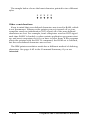
With the two SelecType buttons, you can produce any of the four
typestyles shown below:
NLQ can also be condensed for more characters on a line.
Draft is for fast printing and NLQ for higher-quality work. In the
condensed mode all characters are about 60% of their normal width.
Two NLQ fonts are available: Roman and Sans Serif. You select
them by using the FORM FEED and LINE FEED buttons while the
printer is on line. The FORM FEED button selects Roman, and the
LINE FEED button selects Sans Serif, A software command to change
the NLQ typeface is also available in the Epson mode.
NLQ Roman is clear and typewriter-like.
NLQ
Sans
Serif
is
c r i s p and
distinctive.
If you want NLQ printing, simply press the NLQ button. If you want
condensed printing, simply press the CONDENSED button.
When you press either SelecType button, it beeps twice and its
orange indicator light turns on to show that you have selected it. If you
1.14
Setting Up Your FX Printer
want to turn off either mode, press its button again. It beeps once and
the indicator light turns off to show that the mode is cancelled.
As you can see, SelecType makes it easy to choose either NLQ or
condensed, and the indicator lights always tell you which modes you’ve
selected.
Trying out SelecType is a simple three-step process:
1. Create a short sample document or file with your favorite
application program.
2. Press either or both of the SelecType buttons.
3. Print the document or file using your application program’s print
command.
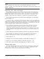
If SelecType Does Not Work
Some applications programs are designed to control all typestyle
functions. Before each printing operation, these programs cancel all
previous typestyle settings by sending a signal (INIT) or by sending
specific control codes to cancel certain typestyles. These signals or
control codes may cancel your SelecType settings.
One reset signal, however, does not affect your SelecType settings.
This is the ESC @ command.
You can see whether your program is changing your settings by
watching the buttons when printing starts. If the lights change, the
program is controlling the typestyles.
If your application program changes your SelecType settings, you
have two choices:
1. Use the program’s setup procedure (which could be called by
another name, such as install) to remove the codes that interfere
with your SelecType settings.
2. Use the print control codes for your application program instead of
SelecType to control your printing. Most programs that cancel
SelecType settings also have sophisticated print control commands
that give the same results that SelecType does. The manual for your
program should explain the necessary commands.
Setting Up Your FX Printer
1-15
Note
Also remember that control codes in your document will override the
SelecType settings. Therefore, if you have a code for NLQ in your
document and you press the DRAFT SelecType button, your printing
will still be in NLQ.
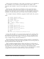
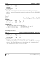
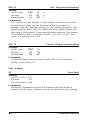
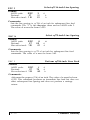
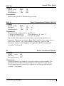
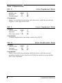
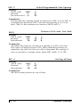
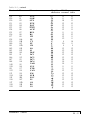
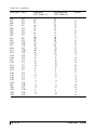
8 Running the Self Test
The FX has a built-in self test that prints out the characters in its
memory so that you can see that the printer is working properly.
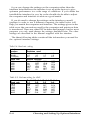
The self test also prints the settings of the printer’s DIP switches.
You’ll use this part of the printout in the last section of this chapter.
Before running the self test, make sure that the power is OFF and
paper is loaded in the printer. (Use wide paper in the FX-286e to avoid
printing on the platen.)
To run the self test in the Near Letter Quality (NLQ) mode, hold
down the FORM FEED button at the same time you turn the printer on.
When the printing starts, release the FORM FEED button.
The self test first prints the version number of the printer and several
lines of settings that are explained in the last section of this chapter.
Then it prints the characters from its memory. The test continues until
you turn the printer off. Part of a typical self test is shown below.
Character mode
Normal
1-1 OFF
Shape of zero
0 (Unslashed)
1-2 OFF
CG Table
Italic6
1-3 OFF
Protocol mode
ESC/P
1-4 OFF
Print Quality
Draft
1-5 OFF
Country
U.S.A.
1-6 ON 1-7 ON 1-8 ON
Page Length
11 inch
2-1 OFF
CSF Mode
Invalid
2-2 OFF
Skip Perforation
None
2-3 OFF
Auto LF
2-4 OFF
Depend on I/F
!"#$%&'()*+,-./0123456789:;<=>?@ABCDEFGHIJKLMNOPQRSTUVWXYZ[
!"#$%&'()*+,-./0123456789:;<=>?@ABCDEFGHIJKLMNOPQRSTUVWXYZ[\
"#$%&'()*+,1./0123456789:;<=>?@ABCDEFGHIJKLMNOPQRSTUVWXYZ[\]
#$%&'()*+,-./0123456789:;<=>?@ABCDEFGHIJKLMNOPQRSTUVWXYZ[\]~
$%&'()*+,-./0123456789:;<=>?@ABCDEFGHIJKLMNOPQRSTUVWXYZ[\]%&'()*+,-./0123456789:;<=>?@ABCDEFGHIJKLMNOPQRSTUVWXYZ[\]!-.
&'()*+,-./0123456789:;<=>?@ABCDEFGHIJKLMNOPQRSTUVWXYZ[\]-.a
'()*+,-./0123456789:;<=>?@ABCDEFGHIJKLMNOPQRSTUVWXYZ[\]-.ab
()*+,-./0123456789:;<=>?@ABCDEFGHIJKLMNOPQRSTUVWXYZ[\]~-.abc
1-16
Setting Up Your FX Printer
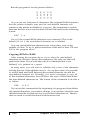
To run the same test in the draft mode, hold down the LINE FEED
button instead of the FORM FEED button while you turn the printer on.
The FX cannot print a draft self test, however, if the NLQ DIP switch is
on. Therefore, if the Print Quality line of the self test printout says NLQ,
you cannot print a draft test without changing a DIP switch.
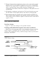
9 Connecting the Printer to Your Computer
Your FX printer communicates with your computer through a
Centronics® compatible parallel interface. If your computer uses this
type of interface and you have a suitable cable, you can connect your
computer immediately. (Be sure that your cable is a shielded cable.)
If you do not know what kind of interface your computer requires,
consult its manual or your dealer. For information on optional
interfaces available from Epson, see Appendix E, and for further
information on the standard interface, see Appendix F.
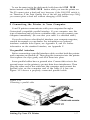
The parallel interface
Before connecting a parallel interface cable, see that both the printer
and computer are turned off. Then plug the connector into the printer.
Next squeeze the clips gently and click them into place.
Some parallel cables have a ground wire. Connect this wire to the
ground screw on the printer to protect data from interference. Then
plug the other end of the cable into the computer and connect the
ground wire on the computer end of the cable if it has one.
Figure 1-13 shows a properly connected parallel cable.
Figure 1-13.
Connecting a parallel cable
Setting Up Your FX Printer
1-17
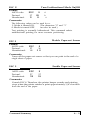
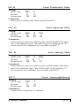
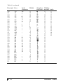
10 Choosing the Operating Mode with DIP Switches
The FX has 12 switches that allow you to change many of the
printer’s settings to suit your individual needs. You may need to change
one or two of them now. These switches, known as DIP (Dual In-line
Package) switches, are in the back of the printer. See Figure 1-14.
Figure 1-14.
DIP switch location
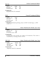
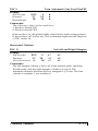
The switches are in two groups and are numbered, as shown in
Figure 1-14. As you can see in the example below, the first part
of the self test shows the settings of the switches. You will find
your own self test printout helpful as you use this section.
Character mode
Normal
1-1 OFF
Shape of zero
0 (Unslashed)
1-2 OFF
CG Table
Italics
1-3 OFF
Protocol mode
ESC/P
1-4 OFF
Print Quality
Draft
1-5 OFF
Country
U.S.A.
1-6 ON 1-7 ON 1-8 ON
Page Length
11 inch
2-1 OFF
CSF Node
Invalid
2-2 OFF
Skip Perforation
None
2-3 OFF
Auto LF
Depend on I/F
2-4 OFF
.!"#$%&'()*+,-./0123456789:;<=>?@ABCDBFGHIJKLMNOPQRSTUVWXYZ[
!"#$%&'()*+,-./0123456789:; <=>?@ABCDEFGHIJKLMNOPQRSTUVWXYZ[\
"#$%&'()*+,-./0123456789:;<=>?@ABCDEFGHIJKLMNOPQRSTUVWXYZ[\]
#$%&'()*+,-./0123456789:;<=>?@ABCDEFGHIJKLMNOPQRSTUVWXYZ[\]~
1-18
Setting Up Your FX Printer
Before you change any DIP switch settings, turn the printer around
to give you easy access to the switches. Then you can easily turn the
switches on and off with a thin pointed object, such as a small
screwdriver or the cap of a ballpoint pen. The switches are ON when
they are UP, and OFF when they are DOWN.
Note
When you change a DIP switch setting, turn off the power, reset the
switch or switches, then turn on the power again. The printer checks
and recognizes new settings only at the time you turn the power on.
The operating mode
The FX has two operating modes, ESC/P® and IBM® printer
emulation mode. ESC/P stands for Epson Standard Code for Printers,
a powerful set of commands developed by Epson and supported by
almost all application software for personal computers. This is the
mode that you should find the most useful and valuable for your
printing. The rest of this manual refers to the ESC/P mode simply as
the Epson mode.
The IBM printer emulation mode is for software that is designed only
for IBM printers. It is not necessary to use this mode for your FX to be
compatible with IBM computers. As you can see from the list of Epson
and IBM printer emulation mode commands in Appendix A, the
Epson mode has more commands and many more capabilities.
There are only two cases in which you may want to use the IBM
printer emulation mode:
1. Your software lists only IBM printers in its printer selection menu.
2. You need to use the following characters and your application
software will not print them in the Epson mode:
If you select IBM printer emulation mode with the DIP switch and
choose an IBM printer in your software’s printer selection menu, your
FX will behave as an IBM printer does. You can use most software that
supports IBM printers, but you will notice that the commands do not
allow you access to all the features of your Epson printer.
Setting Up Your FX Printer
1-19
DIP switch 1-4 controls the choice of operating modes. Turning the
switch OFF selects Epson mode, and turning it ON selects IBM printer
emulation mode.
The Epson character graphics set
Half of the characters used by IBM PCs and compatibles are special
character graphics and international characters. Most previous Epson
printers printed italics instead of these characters. With the FX-86e and
FX-286e, however, you can print the character graphics without losing
italics or any of the power of the Epson commands.
DIP switch 1-3 controls the choice between the italic and the
character graphic table (called CG table in the DIP switch printout).
Turning the switch ON selects the character graphic table, and turning
it OFF selects the italic table. Remember that italics are available even
if you select the character graphic table.
Making the choice
The decision you make about the operating mode and the character
graphics set depends upon the software you use. For most applications,
choose the Epson mode and the Character Graphics set (DIP switch
1-4 OFF and DIP switch 1-3 ON). That way you can set up your
software for an Epson printer and have the full power of the Epson
commands.
If you have trouble printing italics, change DIP switch 1-3 to OFF to
choose italics instead of character graphics. On the other hand, if you
have trouble printing character graphics, change the printer to IBM
printer emulation mode by setting DIP switch 1-4 ON and set your
software to match.
WARNING
You must always be careful to set up your printer and software to
match. Although the IBM commands are based on some of the Epson
commands, important differences affect much software. These
differences can cause erratic printing. In particular, line spacing and
page layout are likely to be wrong, and extra characters may appear.
Other DIP switch settings
Appendix D summarizes all the DIP switch settings in a group of
tables. See that appendix for reference and further information.
1-20
Setting Up Your FX Printer
Chapter 2
Choosing and Loading Paper
The FX printer can accommodate many different sizes and types of
paper, using either its automatic single-sheet loading feature or its
adjustable tractor.
The easy-to-use tractor can handle a wide range of paper widths, and
the automatic single-sheet loading feature handles individual sheets
quickly and easily. For greater efficiency with individual sheets you can
add an optional automatic sheet feeder.
Choosing Paper
Without any accessories, you can use single-sheet paper from 7¼ to
8½ inches wide (up to 14½ inches on the FX-286e) and continuous
paper from 4 to 10 inches wide (up to 16 inches on the FX-286e)
including the perforated edge strips.
Carbon copies
If you use multi-part forms or carbon copies in the FX, use no more
than three sheets or parts at a time, with a total thickness of no more
than 0.25 mm. Also change the paper thickness setting as described at
the end of this chapter.
Using Single-sheet Paper
The automatic sheet loading feature of the FX gives you short
printing times by combining fast loading with fast printing.
If you print large amounts on single sheets of paper, however, you
may find it more convenient to use an automatic sheet feeder. This is
an optional device that holds a stack of paper and inserts a new sheet
whenever required, making single sheets as easy and convenient to use
as continuous paper. The automatic sheet feeder has its own user’s
manual.
Choosing and Loading Paper
2-1
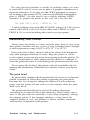
Before you load single-sheet paper the first time, you must prepare
the printer by removing the tractor unit and installing the paper guide,
as described in the next five steps. (If you have previously loaded
continuous-feed paper, you have already done some of the steps.)
Preparing the printer
1. Remove the tractor cover that comes installed on the printer. To
remove it, simply pull the back of the cover toward you until it is
vertical. Then lift the cover up and off the printer.
2. Be sure that you have removed the protective items as described on
page 1-2.
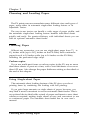
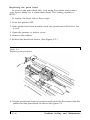
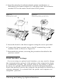
3. Remove the tractor unit. Simply press the release levers (shown in
Figure 2-1) with your thumbs, rock the tractor unit back, and lift it
off the printer.
Figure 2-1.
Removing the tractor unit
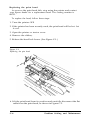
4. Move the edge guides on the paper guide to accomodate the
width of the sheet of paper.
2-2
Choosing and Loading Paper
5. Hold the paper guide above the printer. Insert the right hinge
tab into the right tab slot, as shown in Figure 2-2. Next, insert
the left tab into the left slot. When both tabs are in the slots,
push the guide back so that it is horizontal, and then pull it
toward you until it stops at an angle (about 45 degrees).
Figure 2-2.
Installing the Paper guide
Choosing and Loading Paper
2-3
Loading the paper
Now you are ready to load single-sheet paper. Just follow the steps
below:
1. Turn the printer ON first. Do not put the paper in the printer
before you turn it on.
2. Push both the paper release lever and the paper bail lever
toward the back of the printer. (Figure 2-2 shows where these
levers are.)
3. Make sure the ON LINE light is OFF. If it is ON, press the ON LINE
button once.
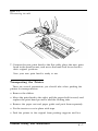
4. Place the paper on the paper guide as shown in Figure 2-3
below. Push the paper firmly into the printer; then let go of it.
Figure 2-3.
Inserting the paper
2-4
Choosing and Loading Paper
5. Pull the paper bail lever forward. This makes the paper feed into the
printer.
6. When the paper stops, push the paper bail lever back.
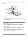
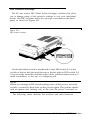
7. Hold the printer cover vertically and fit the notches in its front
corners over the pins at the front of the printer case (as shown in
Figure 2-4). Then tilt the cover back into place.
Figure 2-4.
Installing the printer cover
When you have learned this procedure, you’ll probably leave the
cover on when you load single-sheet paper. If you wish, you can raise
the cover to the vertical position while you’re loading the paper. The
two icons (small pictures) on the printer cover will help you remember
the correct positions of the levers.
Now you are ready to print on single-sheet paper.
Choosing and Loading Paper
2-5
If the paper does not load
If the platen (the black roller) turns but the paper does not load,
remove the paper from the printer and try again, starting at Step 2.
This time press the paper a little more firmly into place.
If nothing happens at all, see that the printer is ON and that the
ON LINE light is off. Then remove the paper and try again.
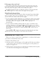
Reloading during printing
When you print a document more than one page long using single
sheets of paper, there are two different ways your software can allow
you to load a new sheet at the end of a page.
l
l
If your software sends characters in a continuous stream, the printer
stops printing when it reaches the bottom of the paper and sounds
the beeper. When this happens, the ON LINE light goes off
automatically.
If your software handles printing page by page, it probably stops
sending characters at the end of a page and prompts you to insert
more paper. In this case the ON LINE light probably remains on, and
the first thing you should do is press the ON LINE button once to
turn it off.
Once the ON LINE light is off, remove the sheet that has just been
printed and load a new sheet in the same way as before.
Reinstalling the Tractor Unit
When you want to switch from single-sheet to continuous-feed paper,
you need to reinstall the tractor unit.
1. Remove the printer cover.
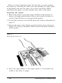
2. Hold the tractor with the gears to the right and fit the rear notches
on the tractor unit over the rear mounting pins on the printer, as
shown in Figure 2-5.
3. Tilt the tractor unit toward you until the front latches click in place
over the front mounting pins on the printer.
2-6
Choosing and Loading Paper
Figure 2-5.
Reinstalling the tractor unit
Choosing and Loading Paper
2-7
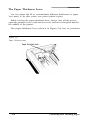
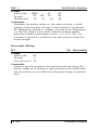
The Paper Thickness Lever
You can adjust the FX to accommodate different thicknesses of paper.
You need to do this when you print carbon copies.
Before moving the paper thickness lever, always turn off the power,
open the printer cover or the tractor cover, and move the print head to
the middle of the printer.
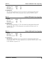
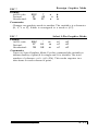
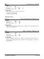
The paper thickness lever (shown in Figure 2-6) has six positions.
Figure 2-6.
Paper thickness lever
2-8
Choosing and Loading Paper
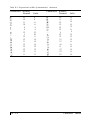
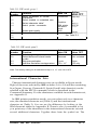
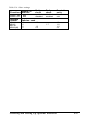
If you want to change or check the lever, push it toward the platen
(the black roller) until it stops. This is the first position. Then pull the
lever toward you. You will feel three more click stops. The table below
shows which position you should use.
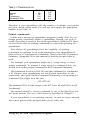
Table 2-I. Paper thickness lever positions
Paper
thickness
Lever
position
Single
With 1 copy
With 2 copies
2nd
3rd
4th
*Maximum total thickness IS 0.25mm
Position 1 is for thinner paper, and positions 5 and 6 are for
thicker paper. These positions should rarely be used. If they are,
the printing quality will not necessarily be as good as on paper as
specified in the technical specifications.
Always return the lever to the second position when you resume
printing on normal paper.
Choosing and Loading Paper
2-9
Chapter 3
Using the FX with Application Programs
Now that you’ve set up and tested the printer, you need to start
using it with your application programs.
Printer Selection Menus
Most application programs let you specify the type of printer you’re
using so that the program can take full advantage of the printer’s
features. Many programs provide an installation or setup procedure
that presents a list of printers to choose from. If your application
program has a printer selection menu, use the instructions below.
The rest of this chapter covers word processors, spreadsheets,
graphics programs, and programming languages.
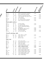
Menu selections
If your software has a printer selection menu, simply choose FX-86e
or FX-286e. If the menu does not list either of these printers, choose
one of the following. They are listed in order of preference.
FX-86e
EX-800
FX-85
FX-80 +
FX-80
FX
LX
Epson printer
Draft printer
FX-286e
EX-1000
FX-286
FX-185
FX-100+
FX-100
FX
LX
Epson printer
Draft printer
If you plan to use the IBM printer emulation mode, choose IBM
Proprinter (if you have an FX-86e), IBM Proprinter XL (if you have an
FX-286e), IBM Graphics printer, or IBM printer, in that order of
preference.
Using the FX with Application Programs
3-1
Note
If your application program does not list the FX-86e or FX-286e, you
may want to contact the manufacturer to find whether an update is
available.
A quick test
After setting up your application program, print a sample document
to be sure the program and the FX are communicating properly. If the
document doesn’t print correctly, recheck the program’s printer
selection and installation procedure. If you’re still having trouble
printing, consult the troubleshooting section in Appendix C.
Computer - Printer Communication
Computers and printers communicate by using codes to represent
characters and commands. To be sure the two devices use the same
codes, almost all manufacturers of computers, printers, and software
use the American Standard Code for Information Interchange, which
is usually referred to by its abbreviation, ASCII.
The ASCII standard includes codes for printable characters (letters,
punctuation marks, numerals, and mathematical symbols) and 33 other
codes called control codes. The control codes are for such functions as
sounding the beeper and performing carriage returns. Because the 33
control codes are not enough to control all possible printer functions,
most printer commands are actually a sequence of two or more codes.
One of the 33 control codes, the escape code, signals the beginning
of a sequence of codes. Therefore, most printer commands are
sequences of codes, the first of which is the escape code. This manual
uses the ASCII abbreviation ESC for this code.
When using control codes to select printer functions for an
application program or programming language, check the manual for
the program or language to find the appropriate method of inserting
the code into the program. Further details on the methods to use are in
the rest of this chapter.
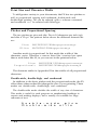
Naming and using commands
The most common way of naming codes or commands is with one of
two numbering systems, decimal or hexadecimal.
3-2
Using the FX with Application Programs
The decimal system is the standard numbering system based on units
of ten, using the numerals O-9.
The hexadecimal, or hex, system is based on units of 16 and is often
used by programmers. Instead of using only the numerals 0 through 9,
the hex system also uses the letters A through F. For example, the
decimal numbers 9, 10, 11, and 12 are 09, 0A, 0B, and 0C in hex.
Since the most frequently used hexadecimal numbers are between 0
and FF hex (0 to 255 in decimal), it’s common to write hexadecimal
numbers that are less than 16 with a zero in front, as shown above.
In this book, hex numbers are distinguished from decimal numbers
by the word hex after them (for example, 1B hex). Other common
ways of denoting a hexadecimal number are the following:
1BH
$1B
&1B
&HlB
<1B>H
The Command Summary and the Quick Reference card give both
the decimal and hex numbers for each command.
Word Processors
In many ways, word processors demand the most from your printer.
When you create and print a document, you may use many print styles
and fonts, add headers and footers, and use bold, italic, and other
effects.
Once you have installed your word processor by using the lists on
page 3-1, you can ordinarily use a fixed set of printer features by using
a word processor command to place markers around the text to be
altered. When the document is printed, the markers are recognized and
translated into suitable commands for your printer. On your screen
some programs show the markers; others display the text as it will
appear-for example, in bold or italics.
This method is normally restricted to features that can be found on
almost all printers, such as bold and underlining.
Some programs also provide a way of placing complete printer
commands in the text. These commands may or may not be visible on
your screen. This method has the advantage of allowing you to use any
printer command, not just a limited set. To make use of it, however,
you need to understand how to use the printer’s commands.
Using the FX with Application Programs
3-3
Check the manual for your word processor to see if you can place
printer commands in your text. If this is possible, use the Command
Summary (Appendix A) in this manual to find the command, and use
the manual for your word processor to find how to assign the
command.
If your FX is not printing correctly, check both the FX and your
word processor and do the following:
l
l
l
l
Make sure you’ve selected the correct printer.
Carefully read the printer setup and installation information in your
word processor’s manual.
Check the printer options that may be part of the installation or
setup section (line feeds, interface, etc.).
Make sure your word processor is capable of sending the proper
commands to your printer.
If you’re still having difficulty printing, check the troubleshooting
section in your word processor’s manual and Appendix C of this
manual.
Spreadsheets
Although spreadsheets seldom use as many printing styles as word
processors, they do have some very specific requirements.
Installation and column width
If your spreadsheet program provides a list of printers, use the list on
page 3-1 to find the proper selection. If your spreadsheet doesn’t have a
printer setup routine, carefully read the program’s manual for
information on printing.
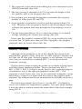
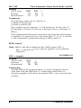
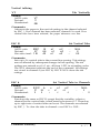
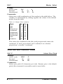
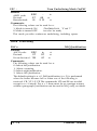
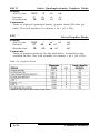
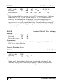
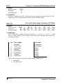
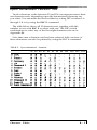
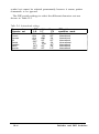
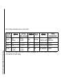
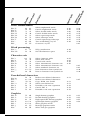
A major concern for printing spreadsheets is the width of the printer.
The FX-86e is an 80-column printer, and the FX-286e is a 136-column
printer. You can, however, increase the number of characters on a line
by using one of the modes in Table 3-1. You can turn on condensed
with a button on the control panel (see SelecType in Chapter 1), and
the other modes are explained in Chapter 4.
3-4
Using the FX with Application Programs
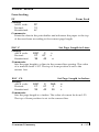
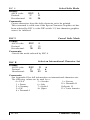
Table 3-1. Characters per line
FX-86e
FX-286e
80
136
Condensed
96
132
233
Condensed Elite
160
272
Normal
Elite
163
Therefore, if your spreadsheet asks the number of columns your printer
can print, decide which mode you will use and supply the appropriate
number from Table 3-1.
Printer commands
Unlike word processors, spreadsheet programs usually don’t let you
change printer commands within a spreadsheet. Instead, one style or
mode of printing is used for the whole spreadsheet. With the FX, there
are two main ways of sending commands to control the printing of a
spreadsheet.
First, almost all spreadsheets have the capability of sending
commands to a printer. Look in the manual for your spreadsheet to
find out how to send printer commands. Then look in the Command
Summary (Appendix A) in this manual to find the proper codes to
send.
For example, your spreadsheet might use a “setup string” to send
printer commands. To prepare a setup string for condensed elite, you
would look up the proper command in the Command Summary.
The command for elite is ESC M, and the command for condensed
is SI. Because most spreadsheets use the decimal equivalent for the
commands, (also given in the Command Summary), a setup string for
condensed elite might look like this:
/027/077/015
The number 027 is for the escape code, 077 is for M, and 015 is for SI
(condensed).
The second method to choose condensed is one of the SelecType control panel buttons. The use of this button is described in Chapter 1.
If your spreadsheet is not printing correctly, be sure you have selected
the correct printer if the program asks you to select one.
Using the FX with Application Programs
3-5
If you’re using the program’s print facility, recheck the FX’s
Command Summary to make sure you’re sending the correct
commands.
If you’re still having difficulty printing, check the troubleshooting
section in your spreadsheet program’s manual or Appendix C of this
manual.
Graphics Programs
The FX is capable of producing finely detailed graphic images.
Although Chapter 5 gives specific information on the graphics
commands, the easiest way to take advantage of the FX’s capabilities is
with one of the many graphics programs available.
When buying graphics software, always make sure it has a suitable
option to allow printouts on an FX printer. Any program with an
option for an FX printer should give excellent results, using different
dot densities to produce a realistic scale of grays.
Most graphics programs have a printer selection procedure, in which
case you should check the lists on page 3-1 to find the proper selection.
Programming Languages
Most users rely on application programs to send commands to the
printer. An awareness of programming languages, however, can be
helpful in exploring a printer’s potential or troubleshooting a printing
problem.
For example, if you want to set up your application program to send
a command for italic printing, you can use a programming language,
such as BASIC or Pascal, to do a quick printout before setting up the
program.
If, on the other hand, you’ve set up a program to send a certain
command to the printer, but it’s not printing correctly, you can send
the same command with a programming language to find whether the
problem lies with your application program, the command, or the
printer.
3-6
Using the FX with Application Programs
Sending printer commands with BASIC
You can send printer commands with any programming language.
The examples in this manual are written in BASIC, because BASIC is
included with most computer systems.
In most forms of BASIC, and in particular Microsoft’” BASIC, the
normal method of producing printed output is to use the LPRINT
statement followed by the text to be printed enclosed in quotation
marks, as shown below:
100 LPRINT "This text will be printed."
Individual printer control codes can be sent by using the CHR$
function with the LPRINT statement:
110 LPRINT CHR$(27);CHR$(69);
This line sends ASCII codes 27 and 69 to the printer, selecting
emphasized printing.
Most versions of BASIC permit the ASCII codes in the CHR$
function to be given in either decimal (as above) or hexadecimal. Also,
if the code corresponds to a printable character, the character itself can
be used in quotation marks in the LPRINT statement. The command
shown above could therefore be given in two other forms:
LPRINT CHR$(27);"E"
LPRINT CHR$(&H1B);CHR$(&H45)
As you can see, Microsoft BASIC uses &H to denote hexadecimal
numbers.
If you have another version of BASIC or a different programming
language, consult the manual for the language to find the correct
formats for these commands.
Using the FX with Application Programs
3-7
Chapter 4
FX Printer Features
You can obtain many different printing effects with the FX printer,
from arranging the printout on the paper to giving extra emphasis to
particular words and phrases. This chapter shows you the features you
may want to select with your software. Once you have read about the
features, you can find their commands in the Command Summary.
SelecType, as you know, controls the printing style of a whole
document. Software commands, on the other hand, can change
anything from a single character to the entire document.
Quality and Fonts
The most fundamental changes you can make to printing on the FX
are in the print quality and NLQ fonts.
The FX has two levels of print quality: draft and NLQ (Near Letter
Quality). Draft printing is fast, making it ideal for drafts and other
preliminary work. NLQ printing takes a little longer, but it produces
more fully-formed characters for presentation-quality documents.
The printout below shows the differences between draft, NLQ
Roman, and NLQ Sans Serif so that you can compare the different
styles and densities:
D r a f t
p r i n t i n g
i s
extremely
f a s t .
NLQ Roman is clear and typewriter-like.
NLQ Sans Serif is crisp and distinctive.
SelecType gives you an easy way of changing the print quality and
NLQ font, but if you prefer to print in NLQ Roman most of the time,
you can select it with a DIP switch (see Appendix D). You can also
choose the print quality and NLQ font with software commands.
FX Printer Features
4-1
Print Size and Character Width
To add greater variety to your documents, the FX has two pitches as
well as proportional spacing and condensed, double-wide and
double-high printing. All can be selected with a software command,
and condensed can be selected with SelecType.
Pitches and Proportional Spacing
The two pitches are pica and elite. Pica is 10 characters per inch (cpi)
and elite is 12 cpi. The printout below shows the difference between the
two.
Pica: ABCDEFGHIJKLMnopqrstuvwxyz
Elite: ABCDEFGHIJKLMnopqrstuvwxyz
Another mode is proportional. In this mode the width of the
characters varies. Therefore, a narrow letter like i receives less space
than a wide letter like W, as you can see in the printout below:
Pica:
Proportional:
ABCDEFGHIJKLMnopqrstuvwxyz
ABCDEFGHIJKLMnopqrstuvwxyz
The character tables in Appendix B list the widths of all proportional
characters.
Double-wide, double-high, and condensed
In addition to the basic pitches and the proportional mode, the FX
offers three other modes that change the size of your printing. These
modes are double-wide, double-high, and condensed.
The double-wide mode doubles the width of any size of characters.
This mode is useful for such purposes as emphasizing headings in
reports and making displays, but is usually not suitable for large
amounts of text.
D o u b l e - w i d e
D o u b l e - w i d e
4-2
p i c a
e l i t e
FX Printer Features
Another mode for headings and other special uses is double-high,
which is shown below.
This is double high printing
Because of its height you must leave a blank line above a line of
double-high. Otherwise the double-high letters will overlap the letters
on the previous line.
Pica and elite can be reduced to about 60% of their normal width
with the condensed mode. This mode is particularly useful for printing
wide spreadsheets because condensed elite allows you up to 160
characters on an B-inch line and 272 on a 13½-inch line.
Condensed can be selected with SelecType, by setting a DIP switch
(see Appendix D), or with a software command. Even if you turn
condensed on with the DIP switch, you can still turn it off with
SelecType or the software command.
Condensed pica gives more characters on a line.
Condensed elite gives you even more.
Widening or narrowing the characters also widens or narrows the
spaces between words and letters. Because word processors usually
create a left margin by printing spaces, you may need to change the
number of characters on a line to keep the margins correct if you
change widths. For example, a left margin of five pica characters is the
same as one of six elite characters.
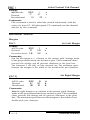
Special Effects and Emphasis
The FX offers two ways of emphasizing parts of your text and also
allows you to use underlining, superscripts, and subscripts. These
features can be controlled only by software commands, but many
application programs can produce them if they are properly installed.
Emphasized and double-strike modes both slow the printer down
slightly to produce bolder text. In emphasized mode, the FX prints
each character twice as the print head moves across the paper, with the
second slightly to the right of the first. This produces darker, more
fully-formed characters.
FX Printer Features
4-3
In double-strike mode, the FX prints each line twice, with the second
slightly below the first. This makes the characters bolder. While NLQ is
in use, however, double-strike is ignored because NLQ characters are
already formed by two passes of the print head.
This is normal NLQ printing
This is emphasized NLQ printing
Superscripts and subscripts are valuable for such purposes as printing
footnote numbers or parts of mathematical formulas, and the underline
mode provides an automatic way of underlining fully any piece of text.
It underlines spaces, subscripts, and superscripts without a break.
The example below shows underlining with text and combined with
superscripts and subscripts in a mathematical formula.
average = (a1 + a2 + . . . . . + an)
n
Using Different Character Sets
The FX incorporates a new character set: Epson Character Graphics.
This set allows you to take advantage of the power of the Epson mode
commands and still print out the character graphics used by IBM and
compatible computers and by much commercial software. For example,
if your word processor can include the characters to draw boxes and
shade areas, you can produce some very professional effects.
You can select the Epson character graphics set with your software or
by setting DIP switch 1-3 ON. For many applications it is best to use
the DIP switch instead of the software command because the character
graphics are then available as soon as you turn the printer on.
4-4
FX Printer Features
The other important change you can make to the standard character
set is to change some characters for ones commonly used in other
languages-chiefly European and Scandinavian-such as accented
characters and symbols. In Epson mode, eight international character
sets can be selected by setting DIP switches 1-6 to 1-8: USA, French,
German, UK, Danish, Swedish, Italian, and Spanish. See Appendix D
for the DIP switch settings.
In Epson mode, these eight, and five more, can also be selected by a
software command. The additional character sets are the following:
Norwegian, a second Danish set, Japanese, a second Spanish set, and
Latin American. A complete list of these characters is in Appendix B.
Also, all text characters can be printed in italics in Epson mode. You
can use this typestyle for special emphasis or as an alternative typeface.
Italics give e m p h a s i s
They
are
an
to
attractive
words.
alternative
style.
Page Layout and Other Commands
The remaining commands in the command summary are not
normally needed when using commercial software. You may need some
of them if you are using a printer installation program provided with
an application package, but most deal with features (such as tabs,
margins, and line spacing) that are provided directly by commercial
programs and are therefore only useful to you if you want to program
the printer using a programming language such as BASIC.
FX Printer Features
4-5
Chapter 5
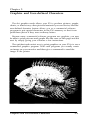
Graphics and User-defined Characters
The dot graphics mode allows your FX to produce pictures, graphs,
charts, or almost any other pictorial material you can devise, and the
user-defined character feature allows you or a commercial software
program to put special characters in the FX’s memory so that it can
print them just as if they were ordinary letters.
Because many commercial software programs use graphics, you may
be able to print pictures and graphs like the ones on this page and the
next by simply giving your software a few instructions.
The quickest and easiest way to print graphics on your FX is to use a
commercial graphics program. With such programs you usually create
an image on your monitor and then give a command to send the
image to the printer.
Graphics and User-defined Characters
5-1
If you use commercial software that produces graphics, all you need
to know about dot graphics is how to use the software. If, on the other
hand, you wish to do your own programming or merely wish to
understand how the FX prints graphics, read on.
The Print Head
To understand dot graphics you need to know a little about how the
FX’s print head works.
The FX’s print head has nine pins. As it moves across the page,
electrical impulses cause the pins to fire. Each time a pin fires, it strikes
the inked ribbon and presses it against the paper to produce a small
dot. As the head moves across the paper, the pins fire time after time in
different patterns to produce letters, numbers, or symbols.
5-2
Graphics and User-defined Characters
Dot patterns
The FX’s print head is able to print graphics in addition to text
because graphic images are formed on the FX about the same way that
pictures in newspapers and magazines are printed.
If you look closely at a newspaper photograph, you can see that it is
made up of many small dots. The FX also forms its images with
patterns of dots, as many as 240 dot positions per inch horizontally and
72 dots vertically. The images printed by the FX can, therefore, be as
finely detailed as the one on the first page of this chapter.
In its main graphics mode the FX prints one column of dots for each
code it receives, and it uses only the top eight of the nine pins.
Therefore, your graphics program must send codes for dot patterns,
one number for each column in a line. For each of those columns the
print head prints the pattern of dots you have specified.
To print figures taller than eight dots, the print head makes more
than one pass. The printer prints one line, then advances the paper
and prints another, just as it does with text.
To keep the print head from leaving gaps between the graphics lines
as it does between the text lines, the line spacing must be changed to
eliminate the space between lines. With a change in line spacing, the
FX can print finely detailed graphic images that give no indication that
they are made up of separate lines, each no more than 8/72nds of an
inch tall.
Each pass of the print head prints one piece of the total pattern,
which can be as tall or short and as wide or narrow as you desire. You
don’t have to fill the whole page or even an entire line with your
graphics figures. In fact, you can use as little or as much space as you
like for a figure and put it anywhere on the page.
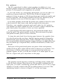
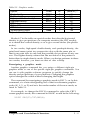
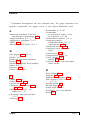
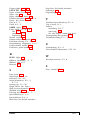
Pin Labels
The graphics mode requires a method to tell the printer which pins
to fire in each column. Since there are 256 possible combinations of
eight pins, you need a numbering system that allows you to use a single
number to specify which of the 256 possible patterns you want. This
numbering system is shown in Figure 5-1 on the next page.
Graphics and User-defined Characters
5-3
To fire any one pin, you send its number. To fire more than one pin
at the same time, add up the numbers of the pins and send the sum to
the printer. Therefore, with these labels for the pins, you fire the top
pin by sending 128. To fire the bottom pin, you send 1. If you want to
fire only the top and bottom pins, you simply add 128 and 1, then
send 129.
By adding the appropriate label numbers together, you can fire any
combination of pins. Figure 5-1 shows three examples of how to
calculate the number that fires a particular pattern of pins.
Figure 5-1.
Pin numbering system
128
64
32
16
8
4
2
1
128
32
8
2
170
128
64
32
16
8
4
2
1
64
8
2
74
128
64
32
16
8
4
2
1
128
4
2
134
With this numbering system, any combination of the eight pins adds
up to a decimal number between 0 and 255, and no numbers are
duplicated. Before you can put these numbers in a graphics program,
however, you need to know the format of the graphics commands.
Graphics Commands
The graphics mode commands are quite different from most other
commands. For most of the other modes, such as emphasized and
double-wide, one command turns the mode on and another turns it
off. For graphics, the command is more complicated because the
command that turns on a graphics mode also specifies how many
columns of graphics will be printed. After the printer receives this
command, it interprets the next numbers as pin patterns and prints
them on the paper.
5-4
Graphics and User-defined Characters
The graphics command format
There are several different graphics commands giving different
horizontal dot densities and printing speeds. Because the format is
almost the same for all the commands, however, the example here
keeps things simple by using only the single-density graphics command,
ESC K. In single-density graphics, there are 60 dots per inch
horizontally.
The command to enter single-density graphics mode is ESC K nl n2.
In BASIC the command is given in this format:
LPRINT CHR$(27);"K";CHR$(nl);CHR$(n2);
ESC K specifies single-density graphics, and the next two numbers
(nl and n2) specify the number of columns reserved for graphics.
Column reservation numbers
Even in single-density graphics mode, one 8-inch line can
accommodate 480 columns of graphics; in quadruple-density, almost
2000 columns can fit on the same 8-inch line. Since the printer does
not use decimal numbers larger than 255, the graphics commands use
two numbers for reserving columns.
Because the commands are set up for two numbers, you must supply
two even if you need only one. When you need fewer than 256
columns, it is easy to determine nl and n2: nl is the number of
columns you are reserving and n2 is zero. For example, to send data for
200 columns of graphics, nl is 200 and n2 is 0.
For more than 256 columns of graphics data, n2 is the number of
complete groups of 256 columns, and n1 is the number of columns to
complete the line. For example, to send 1632 columns of graphic data,
nl is 96 and n2 is 6 because 96 + (6 x 256) = 1632.
You can calculate both nl and n2 by dividing the total number of
columns by 256. The quotient is n2 and the remainder is nl. If you are
using a programming language with MOD (modulus) and INT (integer)
functions, you can use the following formulas, in which n is the total
number of columns.
n1 = n MOD 256
n2 = INT (n/256)
Graphics and User-defined Characters
5-5
Graphics data
After receiving a graphics command such as ESC K nl n2, the
printer prints the number of codes specified by nl and n2 as graphics
data, no matter what codes they are. This means that you must be sure
to supply exactly the right amount of graphics data. If you supply too
little, the printer will stop and wait for more data and will seem to be
locked. The next data sent will then be printed as graphics, even if it is
really text. On the other hand, if you supply too much graphics data,
the excess will be printed as regular text.
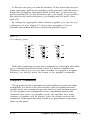
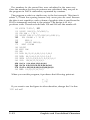
Simple Graphics Programming
The first example in this section shows how a graphics command,
column reservation numbers, and data can be used to print a single
line of graphics. The example is a BASIC program. If you prefer
another programming language, the principles are exactly the same.
Therefore, you can easily adapt the program to the language you prefer.
The first line of the program specifies single-density graphics for 40
columns:
100 LPRINT CHR$(27);"K";CHR$(40);CHR$(0);
The second line is the data that is printed as pin patterns. It uses the
number 74 to produce one of the patterns shown in Figure 5-1. The
FOR-NEXT loop sends 40 columns of data.
200 FOR X=1 TO 40: LPRINT CHR$(74);: NEXT X
That is the whole program. In BASIC, semicolons at the ends of the
lines are very important; they prevent the computer from sending
other codes after the ones you specify. In other languages you may have
to use a special command to send a single code at a time. Run the
program to see the result below. Although it is not as interesting as the
examples at the beginning of this chapter, it shows exactly how the
mode works.
5-6
Graphics and User-defined Characters
WIDTH statements
Some software (including most versions of BASIC) automatically
inserts carriage return and line feed codes after every 80 or 130
characters. This is usually no problem with text, but it can spoil your
graphics. Two extra columns of graphics are printed in the middle of
the ones you send, and are left over and printed as text.
In some versions of BASIC you can prevent unwanted control
codes in graphics by putting a WIDTH statement at the beginning of
all graphics programs. The format in many forms of BASIC is either
WIDTH “LPTl:“, 255 or WIDTH LPRINT 255. Check your software
manual for the proper format.
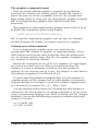
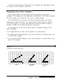
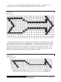
Printing taller patterns
The next example shows how several lines of graphics can be formed
into a figure taller than eight dots. It uses programming techniques for
producing textured or repetitive patterns.
The program is listed below. The lines inside each pair of FOR and
NEXT statements have been indented so that you can see how the
program works; the spaces are not needed for the program to run.
100 WIDTH "LPTl:", 255
110 LPRINT CHR$(27);"A";CHR$(8);
120 FOR R = 1 TO 6
130 LPRINT CHR$(27);"K";CHR$(100);CHR$(0);
140 FOR X = 1 to 50
150
LPRINT CHR$(170);CHR$(85);
160 NEXT X: LPRINT
170 NEXT R
180 LPRINT CHR$(27);"@"
If you run the program, you will see how it combines six print lines
into a pattern.
There are five basic steps that the program goes through to produce
this kind of pattern.
Graphics and User-defined Characters
5-7
1. The computer is prevented from adding any extra characters by the
WIDTH statement (line 100).
2. The line spacing is changed to 8/72 of an inch-the height of the
dot patterns used in the program (line 110).
3. The program goes through the graphics commands the required
number of times (lines 120 and 170).
4. A new graphics command is used for each line printed (lines 130160). This part of the program is similar to the last example, but two
columns are printed each time through the loop making a total of
100.
5. The last important thing to do is to reset the printer to its default
settings, including the normal line spacing (line 180).
Notice that the graphics command (ESC K) can be in effect for only
one print line. To print more than one line of graphics, the graphics
command must be issued before each line.
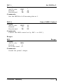
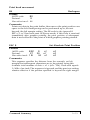
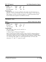
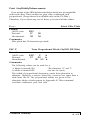
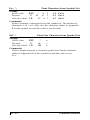
Density Varieties
Although all the examples so far in this chapter have been in the
single-density graphics mode, there are six other eight-pin densities and
two that use all nine pins. Nine-pin graphics is not necessary for most
uses, but you can find the command (ESC ^) in the Epson mode
command summary.
The four most common eight-pin modes are available in both Epson
and IBM printer emulation modes. Their commands are ESC K,
ESC L, ESC Y, ESC Z. In Epson mode, there is also a general-purpose
command for any of the eight-pin graphics modes: ESC *. This
command is used in the same way as the individual commands, except
that before n1 and n2 you must send the code for the graphics mode
required. The different modes are summarized in the table on the next
page.
The following example shows how to use the ESC * command to
reserve 40 columns for single-density graphics. This uses mode number
0 from the table to achieve exactly the same effect as the first example
using ESC K.
LPRINT CHR$(27);"*";CHR$(0);CHR$(40);CHR$(0);
5-8
Graphics and User-defined Characters
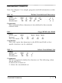
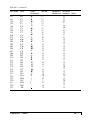
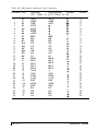
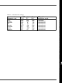
Table 5-1. Graphics modes
Option
Single-density
Double-density
High-speed double-density*
Alternate
Code
Quadruple-density*
CRT I
Plotter (1:1)
ESC K
ESC L
ESC Y
ESC Z
none
none
CRT II
Double-density plotter
none
none
m
0
1
Horiz. density
(dots/in.)
60
120
2
3
120
4
5
80
72
6
7
144
240
90
*Adjacent dots cannot be printed in this mode.
Modes 4-7 in the table are special modes that alter the horizontal
density to give proportions of a computer monitor (the CRT modes),
or to match the vertical density so as to give round circles (the plotter
modes).
In two modes, high-speed double-density and quadruple-density, the
print head cannot print two consecutive dots with the same pin, so
that it can print dots in only half the possible dot positions in any one
row. The higher density means that the resolution of the pattern is
better than in single-density mode. When you design patterns in these
two modes, however, you must see that no dots overlap.
Reassigning a graphics mode
Another graphics command lets you assign a different eight-pin
graphics mode to one of the specific eight-pin graphics commands. You
can use it with graphics software programs to quickly change the
density and proportions of your printouts. Changing the graphics
option changes the width without changing the height.
The command for reassigning a graphics mode is ESC ? c m. In this
command, c is a letter designating one of the four alternate graphics
codes (K, L, Y, or Z) and m is the mode number of the new mode, as
listed in Table 5-1.
For example, to change the ESC K command to select the CRT I
screen graphics mode, the command in BASIC would be the following:
LPRINT CHR$(27);"?K";CHR$(4);
Graphics and User-defined Characters
5-9
A little experimentation should tell you whether the reassigning code
can improve your graphics printouts.
Designing Your Own Graphics
This section takes you through the development of a graphics
program. The example is not especially complicated, but it does include
the same steps you would use for a more complex figure.
You should plan your figure with dots on graph paper, but before
beginning to place the dots, you must decide which graphics density
you want. Figure 5-2 shows the differences between three common
modes so that you can choose the one you want.
In this figure you can see the main rules for graphic design in the
three densities:
l
l
l
In single-density no dots can be placed on vertical lines.
In high-speed double-density, dots can be placed on vertical lines, but
no dots can overlap.
In low-speed double-density, dots can be placed on vertical lines, and
they can overlap.
Figure 5-2.
Designing in different densities
Single
5-10
High-speed
double
Low-speed
double
Graphics and User-defined Characters
Now look at the high-speed double-density design in Figure 5-3. It
should point you in the right direction for your own work.
Figure 5-3.
Arrow design
After plotting the dots on a grid, you calculate the numbers for each
pin pattern by dividing the design grid into separate print lines. For the
arrow design, the grid was divided into two lines, each seven dots high.
Then each column was examined to calculate the graphics data. The
results for the first line are shown in Figure 5-4. The pin values are on
the left and the sums at the bottom of each column.
Figure 5-4.
Calculating data
Graphics and User-defined Characters
5-11
The numbers for the second line were calculated in the same way.
Once the numbers for the pin patterns are calculated, they are put in
the program in DATA statements, separated by commas.
The program works in a similar way to the last example. This time it
selects 7/72-inch line spacing because only seven pins are used. Because
the data is not repetitive, each column of graphics data is read from the
DATA statements and sent to the printer. The design is 41 dot
positions wide. Therefore both lines 130 and 140 use the number 41.
100 WIDTH "LPTl:", 255
110 LPRINT CHR$(27);"A";CHR$(7);
120 FOR ROW = 1 TO 2
130 LPRINT CHR$(27);"Y";CHR$(41);CHR$(0);
140 FOR COLUMN = 1 TO 41
150
READ N
160
LPRINT CHR$(N);
170 NEXT COLUMN
180 LPRINT
190 NEXT ROW
200 END
210 DATA 64,32,80,8,68,2,64,0,64,0
220 DATA 64,0,64,0,32,0,16,0,8,0
230 DATA 8,0,8,0,8,0,8,0,8,0,8,0,8,0
240 DATA 184,64,32,16,8,4,2
250 DATA 8,16,40,64,136,0,8,0,8,0
260 DATA 8,0,8,0,16,0,32,0,64,0,64,0
270 DATA 64,0,64,0,64,0,64,0,64,0,64,0
280 DATA 116,8,16,32,64,128,0
When you run this program, it produces the following printout:
If you want to see the figure in other densities, change the Y in line
130 to L or Z.
5-12
Graphics and User-defined Characters
User-defined Characters
The FX has a command that allows you to define and print
characters of your own design. You can design an entirely new
alphabet or typeface, create mathematical or scientific symbols, or
create graphic patterns to serve as building blocks for larger designs.
These user-defined characters work only in draft mode.
Also, you can buy commercial software programs that assist you in
creating characters or supply you with sets of characters already
created. In addition, some popular application packages make use of
the user-defined character function to enhance printouts. (These
characters are called download characters in some programs.)
The printout below shows a few user-defined characters to give you
an idea of what can be done, but remember that you can create what
you need or want.
When you define a character of your own, the definition is stored in
temporary memory (RAM). The original character with the same code
remains in the printer’s permanent memory (ROM) and you can print
either of them when needed.
Design grids
The process of defining a character is much like printing dot graphics
because you send the printer precise instructions on where you want
each dot printed. In fact, planning a user-defined character is like
planning a small dot graphics pattern.
To design a character you use a grid that has nine rows and eleven
columns. Figure 5-5 on the next page shows three of these grids. Most
characters do not use the two rows below the heavy line. Those rows
are only for characters with descenders, like y and g. Also, even
though you can use up to 11 columns, it is best to leave the last two
blank for the space between characters.
The grid in the middle of Figure 5-5 shows a plan for a character.
Although there are nine pins in the FX print head, you can use only
eight of them in a single user-defined character. The design in
Graphics and User-defined Characters
5-13
Figure 5-5 uses the top eight, but you can also use the bottom eight by
using the grid on the right as explained later in this section.
Once the character is planned on the grid, you simply add the pin
values for each column together, just as you do for graphics. Then, the
next step in defining a character is to send this information to the
printer.
Figure 5-5.
Design grids
128
128
64
64
32
16
32
16
8
8
4
2
1
4
2
1
123456789
128
64
32
16
8
4
2
1
123456789
123456789
Sending the character definition
The command to define characters is complex:
ESC & 0 nl n2 al dl . . . d n
You can define more than one character with a single command.
The values nl and n2 are the ASCII codes of the first and last
characters you are defining. If you are defining only one character, nl
and n2 are the same. You can use any codes between 32 and 127 or 161
and 254 decimal for nl and n2, but it is best not to define decimal 32,
which is the code for a space. You can also use other codes by using the
ESC 6 and ESC I commands (see the Command Summary).
An example will show how to specify nl and n2. If, for instance, you
want to redefine the characters A to Z, nl is A (or ASCII code 65) and
n2 is Z (or ASCII code 90). So the command ESC & 0 AZ (followed
by the appropriate data) would replace the entire alphabet of capital
letters.
5-14
Graphics and User-defined Characters
Following the specification of the range of characters to be defined in
this command is one number (al) that specifies the width of the
character and whether it uses the top eight pins or the bottom eight
pins.
The last part of the character definition is the actual data that
defines the dot patterns for each column of each character. Since a
character can use up to eleven columns, you must supply eleven data
numbers for each character even if some of the columns are blank.
An example character definition program should make the process
clear:
100 LPRINT CHR$(27);"x0";
110 LPRINT CHR$(27);"&";CHR$(0);
120 LPRINT "@@";
130 LPRINT CHR$(l36);
140 FOR I = 1 to 11
READ A: LPRINT CHR$(A);
150
160 NEXT I
170 LPRINT "@ @ @ @ @"
180 LPRINT CHR$(27);"%l";CHR$(1);
190 LPRINT "@ @ @ @ @"
200 LPRINT CHR$(27);"%";CHR$(0);
210 LPRINT "@ @ @ @ @"
220 END
230 DATA 32,80,168,84,42,84,168,80,32,0,0
In line 100, the ESC x 0 command selects draft style printing. The
actual character definition starts in line 110. The two at signs (@) in
line 120 are nl and n2, the range of characters being defined (in this
case, a range of one). Line 130 contains a1.
The information about the character design (which is contained in
the data statements at the end of the program) is sent to the printer in
the loop between lines 140 and 160.
This example program defines a heart and places it in the area of
RAM reserved for ASCII code 64, which corresponds to the at sign in
the characters in the ROM. The next part of the program (lines
170-210) prints out a three-line sample. The first and third lines contain
at signs; the second line contains the heart that was defined.
Graphics and User-defined Characters
5-15
Run the program to see the printout below:
As you can see, both sets of characters (the original ROM characters
that the printer normally uses and the user-defined character set)
remain in the printer available for your use. The command to switch
between the two sets is used in lines 180 and 200 and has the following
format:
ESC % n
If n is 0, the normal ROM character set is selected. (This is the
default.) If n is 1, the user-defined character set is selected.
You can switch between character sets at any time, even in the
middle of a line. To try it, place semicolons at the end of lines 170 and
190 in the program above.
Copying ROM to RAM
After running the program above, if you select the user-defined
character set and try to print other characters, the only one that will
print is the heart. If you send the code for a character that is not
defined, it is printed as a space.
In many cases, you will want to redefine only a few of the characters,
leaving the rest of the alphabet as it is. As you have seen, it is possible
to switch back and forth between the normal character set and the
user-defined character set. Normally, it is more convenient to copy all
of the standard characters from ROM to the area of RAM that holds
the user-defined character set. The format of the command to do this is
as follows:
ESC : 0 0 0
If you use this command at the beginning of a program, then define
the special characters you want to change, you can then select the userdefined character set and use it as your normal character set. There is
then no need to switch back and forth between sets.
5-16
Graphics and User-defined Characters
Note
This command will cancel any user-defined characters you have
already created. You must send this command to the printer before you
define characters.
Specifying the width and height
The example program uses 136 for al (in line 130 of the definition
program), but you can use other values. The number a1 specifies two
things: the width of the character and its position on the grid. The
width is used when the character is printed in proportional mode.
If you want a character to use the bottom eight pins, use the third
grid in Figure 5-5.
A value of 136 is suitable for all characters that use the top eight pins
and start in column I and finish in column 9. For a character the same
width, but printed with the bottom eight pins, al should be 8. For any
other character follow these rules to calculate al :
1. If you design a character narrower than nine columns, you can
balance the number of empty columns on either side with the
following method: Starting with a1 equal to 8, subtract 1 for every
blank column on the right and add 16 for every blank column on
the left.
2. If the character should be printed with the top eight pins, add 128.
For example, if a character uses the top eight pins and starts in
column 3 and ends in column 7, the calculation is as follows:
l
start with al = 8
l
subtract 2 for two blank columns on the right, giving a1 = 6
l
add 32 for two blank columns on the left, giving a1 = 38
l
add 128 to print with the top eight pins, so that a1 = 166.
Mixing print styles
The user-defined characters can be used in combination with most
print styles (except NLQ, of course). For example, emphasized and
double-wide work well with user-defined characters.
Graphics and User-defined Characters
5-17
The sample below shows the heart character printed in two different
styles.
Other considerations
Keep in mind that user-defined characters are stored in RAM, which
is not permanent. Whenever the printer power is turned off or your
computer sends an initialization (NT) signal, all of the user-defined
characters are lost. For example, some computers send an INIT signal
each time BASIC is loaded or when certain application programs start
up, and most computers do it if you have to reset them. If the program
resets the printer with the ESC @ command, the ROM set is selected,
but the user-defined characters are not lost.
The IBM printer emulation mode has a different method of defining
characters. See page A-45 in the Command Summary if you are
interested.
5-18
Graphics and User-defined Characters
Appendix A
Command Summary
This appendix lists and describes all the commands, both Epson
(ESC/P) mode and IBM printer emulation mode, available on the FX.
The first part of this appendix lists all commands in numerical order
and gives the page number where each is fully described. If you know
which command you are looking for, consult the numerical list to find
the page number where it is described.
The Quick Reference card at the end of the book also contains a list
of the commands divided by topic, with page number references that
direct you to full explanations of the commands. The numerical list
and the Quick Reference card also show the differences between the
Epson mode and the IBM printer emulation mode.
The second part of this appendix lists and describes Epson mode
commands and IBM printer emulation mode commands separately; the
commands are divided into the following subjects:
Printer Operation
Data Control
Vertical Motion
Horizontal Motion
Overall Printing Style
Print Size
Print Enhancement
Word Processing
Character Sets
User-defined Characters
Graphics
Each command has a format section and a comment section. The
format section gives the ASCII, decimal, and hexadecimal values for
the command; the comment section describes the effect of the
command and gives any additional information necessary for using it.
All three formats are equivalent, and it should be easy to pick the
one most suited to your purpose.
Note
Some application programs can use control key sequences. See the
Control Key chart on page A-3 for information on using these.
Command Summary
A . 1
For the following commands that use only 0 or 1 for the variable,
either the ASCII codes 1 and 0 or the characters 1 and 0 can be used:
ESC S, ESC U, ESC X, ESC p, ESC W, ESC S, ESC - , and
ESC %
For example, in BASIC you can turn on double-wide with either of
these statements:
LPRINT CHR$(27);"W";CHR$(l)
LPRINT CHR$(27);"W";"l"
The simplest type of command consists of a single character to be
sent to the printer. For instance, to print in condensed mode the code
format is:
ASCII code: S I
15
Decimal:
Hexadecimal: OF
This code can be sent from a program by sending the code 15 directly.
More complex commands consist of two or more character codes.
For example, to print in proportional mode the code format is the
following:
ASCII code:
Decimal:
Hexadecimal:
ESC
27
1B
112
70
n
n
n
In this case n can be either 1 or 0, to begin or end proportional
printing. You can use either of the following commands to turn ON
proportional print from BASIC:
LPRINT CHR$(27);CHR$(112);CHR$(l)
LPRINT CHR$(27);"p";CHR$(l)
A-2
Command Summary
Control key chart
Some application programs can use control key codes for decimal
values O-27. The table below gives you the proper values. The Control
Key column indicates that you press the control key at the same time
you press the key for the letter or symbol in that column. For example,
you press the control key and A at the same time to send the value 1.
Some programs that use this system cannot use control-@, and
many programs use the control keys for other purposes.
Dec.
Hex.
Control Key
0
1
2
3
4
5
6
7
8
9
10
11
12
13
14
15
16
17
18
19
20
21
22
23
24
25
26
27
00
01
02
03
04
05
06
07
08
09
0A
0B
0C
0D
0E
0F
@
A
B
C
D
E
F
G
H
I
J
K
L
M
N
O
10
P
11
12
13
14
15
16
17
18
19
1A
1B
Q
R
S
T
U
V
W
X
Y
Z
[
Command Summary
A-3
Commands in Numerical Order
This section lists all the FX commands, with their decimal and
hexadecimal values. The numbers in the columns on the right are the
page numbers in this appendix where a complete description of the
command can be found. If the Epson and IBM printer emulation mode
page numbers are the same, the command is the same in both modes
and is described only in the Epson mode section.
7
BEL
BS
8
HT
9
10
LF
11
VT
12
FF
13
CR
14
SO
15
SI
DC1
17
DC2
18
DC2
18
DC3
19
DC4
20
CAN
24
127
DEL
ESC SO
14
15
ESC SI
ESC EM 25
ESC SP
32
ESC !
33
ESC #
35
ESC $
36
ESC %
37
ESC &
38
ESC *
42
ESC 45
A-4
07 Beeper
08 Backspace
09 Tab horizontally
0A Line feed
0B Tab vertically
0C Form feed
0D Carriage return
0E Select double-wide (1 line)
0F Select condensed mode
11 Select printer
12 Cancel condensed mode
12 Cancel condensed/elite
13 Deselect printer
14 Cancel double-wide (1 line)
18 Cancel line
7F Delete character
0E Select double-wide (1 line)
0F Select condensed mode
19 Automatic sheet feeder on/off
20 Set intercharacter space
21 Master select
23 Cancel MSB control
24 Set absolute print position
25 Select user-defined set
26 Define user-defined characters
2A Select graphics mode
2D Turn underlining on/off
A-11
A-19
A-20
A-14
A-17
A-13
A-12
A-24
A-23
A-7
A-24
A-8
A-25
A-12
A-12
A-24
A-24
A-10
A-29
A-22
A-11
A-19
A-31
A-31
A-34
A-28
A-11
A-19
A-20
A-14
A-17
A-13
A-12
A-24
A-23
A-7
A-42
A-25
A-12
A-24
A-24
A-28
Command Summary
ESC /
ESC 0
ESC 1
ESC 2
ESC 2
ESC 3
ESC 4
ESC 4
ESC 5
ESC 5
ESC 6
ESC 6
ESC 7
ESC 7
ESC 8
ESC 9
ESC :
ESC :
ESC <
ESC =
ESC =
ESC >
ESC ?
ESC @
ESC A
ESC A
ESC B
ESC C
ESC CO
ESC D
ESC E
ESC F
ESC G
ESC H
ESC I
ESC I
47 2F Select vertical tab channel
48 30 Select l/8-inch line spacing
49 3 1 Select 7/72-inch line spacing
50 32 Select l/6-inch line spacing
50 32 Select programmable line spacing
5 1 33 Select n/216-inch line spacing
52 34 Select italic mode
52 34 Set top of form
53 35 Cancel italic mode
53 35 Turn automatic line feed on/off
54 36 Printable code area expansion
54 36 Select international character set
55 37 Cancel ESC 6
55 37 Select standard character set
56 38 Disable paper-out sensor
57 39 Enable paper-out sensor
58 3A Copy ROM into RAM
58 3A Select elite pitch
60 3C Select unidirectional mode (1-line)
61 3D Set MSB to 0
61 3D Define user-defined characters
62 3E Set MSB to 1
63 3F Reassign graphics mode
64 40 Initialize printer
65 41 Select n/72-inch line spacing
65 41 Set n/72-inch line spacing
66 42 Set vertical tabs
67 43 Set page length in lines
67 43 Set page length in inches
68 44 Set horizontal tabs
69 45 Select emphasized mode
70 46 Cancel emphasized mode
71 47 Select double-strike mode
72 48 Cancel double-strike mode
73 49 Printable code area expansion
73 49 Select font
Command Summary
A-18
A-15 A-15
A-15 A-15
A-15
A-38
A-16 A-16
A-30
A-38
A-30
A-39
A-32
A-43
A-32
A-43
A-9
A-9
A-9
A-9
A-31
A-41
A-8
A-10
A-45
A-11
A-35
A-7
A-16
A-37
A-17 A-17
A-13 A-13
A-13 A-13
A-21 A-40
A-26 A-26
A-26 A-26
A-26 A-26
A-27 A-27
A-32
A-40
A - 5
ESC J
ESC K
ESC L
ESC M
ESC N
ESC O
ESC P
ESC I’
ESC Q
ESC Q3
ESC Q22
ESC R
ESC R
ESC SO
ESC S l
ESC T
ESC U
ESC W
ESC X
ESC Y
ESC Z
ESC [@
ESC \
ESC \
ESC A
ESC A
ESC _
ESC a
ESC b
ESC k
ESC l
ESC p
ESC s
ESC t
ESC w
ESC x
A.6
74
75
76
77
78
79
80
80
81
81
81
82
82
83
83
84
85
87
88
89
90
91
92
92
94
94
95
97
98
107
108
112
115
116
119
120
4A Perform n/216-inch line feed
4B Select single-density graphics
4C Select double-density graphics
4D Select elite pitch
4E Set skip-over-perforation
4F Cancel skip-over-perforation
50 Select pica pitch
50 Turn proportional on/off (286e)
5 1 Set right margin
5 1 Deselect printer (86e)
5 1 Deselect printer (286e)
52 International character set
52 Restore default tab settings
53 Select superscript mode
53 Select subscript mode
54 Cancel superscript/subscript
55 Turn unidirectional mode on/off
57 Turn double-wide on/off
58 Set left and right margins
59 High-speed dbl-density graphics
5A Quadruple-density graphics
5B Turn double-high on/off (286e)
5C Set relative position
5C Print characters from symbol set
5E Select 9-pin graphics
5E Print 1 character from symbol set
5F Turn overscore on/off
61 NLQ justification
62 Set vertical tabs in channels
6B Select NLQ font
6C Set left margin
70 Turn proportional mode on/off
73 Turn half-speed mode on/off
74 Select character table
77 Turn double-high on/off
78 Select NLQ or draft
A-16
A-33
A-33
A-23
A-14
A-14
A-22
A-18
A-38
A-33
A-33
A-14
A-14
A-41
A-37
A-37
A-30
A-40
A-27
A-27
A-27
A-9
A-25
A-39
A-33 A-33
A-34 A-34
A-42
A-20
A-44
A-35
A-44
A-43
A-28
A-17
A-21
A-18
A-23
A-8
A-29
A-25
A-21
A-27
A-27
A-27
A-9
A-25
Command Summary
Epson (ESC/P) Commands
The following section lists and describes all the Epson (ESC/P)
commands.
Printer Operation
Initialization
Initialize Printer
ESC @
Format:
ASCII code:
Decimal:
Hexadecimal:
ESC
27
1B
@
40
64
Comments:
Resets the printer mode and clears the buffer of printable data on
the print line preceding the command.
Selection
Select Printer
DC1
Format:
ASCII code:
Decimal:
Hexadecimal:
DC1
17
11
Comments:
Returns the printer to the selected state if it has been deselected by
the printer deselect code (DC3). Does not select the printer if it has
been switched off line by pressing the ON LINE button.
Command Summary
A - 7
Deselect Printer
DC3
Format:
ASCII code:
Decimal:
Hexadecimal:
DC3
19
13
Comments:
Puts the printer into the deselected state until select printer code
(DC1) is received. The printer cannot be reselected with the ON LINE
button.
Speed
Turn Half-speed Mode On/Off
ESCs
Format:
ASCII code:
Decimal:
Hexadecimal:
ESC
27
1B
s
115
73
n
n
n
Comments:
The following values can be used for n:
(The characters “0” and “1”
1: Mode is turned ON.
can also be used.)
0: Mode is turned OFF,
Printing direction
Select Unidirectional Mode (one line)
ESC <
Format:
ASCII code:
Decimal:
Hexadecimal:
ESC
<
27
60
1B
3C
Comments:
Printing is normally bidirectional. This command selects
unidirectional printing for one line only. (It is cancelled by a carriage
return.) The print head moves to the extreme left (home) position,
and printing takes place from left to right.
A-8
Command Summary
Turn Unidirectional Mode On/Off
ESC U
Format:
ASCII code:
Decimal:
Hexadecimal:
ESC
27
1B
U
85
55
n
n
n
Comments:
The following values can be used for n:
(The characters “0” and “1”
1: Mode is turned ON.
can also be used.)
0: Mode is turned OFF.
Text printing is normally bidirectional. This command selects
unidirectional printing for more accurate positioning.
Disable Paper-out Sensor
ESC 8
Format:
ASCII code:
Decimal:
Hexadecimal:
ESC
8
27
1B
56
3 8
Comments:
Turns off the paper-out sensor so that you can print to the end of a
single sheet of paper.
Enable Paper-out Sensor
ESC 9
Format:
ASCII code:
Decimal:
Hexadecimal:
ESC
9
27
57
1B
39
Comments:
Cancels ESC 8. Therefore, the printer beeper sounds and printing
stops when the printer reaches a point approximately 3/4 of an inch
from the end of the paper.
Command Summary
A - 9
ESC EM
Format:
ASCII code:
Decimal:
Hexadecimal:
Turn Automatic Sheet Feed Mode On/Off
ESC
27
1B
EM
25
19
n
n
n
Comments:
The following values can be used for n:
4: Mode is turned ON.
0: Mode is turned OFF.
The variables are the characters “0” (48 decimal or 30 hex) and “4”
(52 decimal or 34 hex). Do not use 1 decimal, 01 hex, 4 decimal, or
04 hex.
The command should not be used unless the automatic sheet feeder
is installed. It is ignored if any value other than “0” or “4” is used for
n. The command overrides the setting of DIP switch 2-2.
MSB control
Note: MSB is the Most Significant Bit. MSB control (ESC = ,
ESC >, and ESC #) is not valid for graphics or user-defined
characters.
Set MSB to 0
ESC = (equal)
Format:
ASCII code:
Decimal:
Hexadecimal:
ESC
27
1B
=
61
3D
Comments:
Sets the MSB of all incoming data to 0. Some computers always
send data with the MSB set to 1, which means that italics or
character graphics will always be printed. ESC = can overcome this
problem.
A-10
Command Summary
ESC >
Format:
ASCII code:
Decimal:
Hexadecimal:
Set MSB to 1
ESC
>
27
62
1B
3E
Comments:
Sets the MSB bit of all incoming data as 1.
Cancel MSB Control
ESC #
Format:
ASCII code:
Decimal:
Hexadecimal:
ESC
#
27
35
1B
23
Comments:
Cancels the MSB control set by ESC = or ESC ).
Beeper
BEL
Format:
Beeper
BEL
ASCII code:
7
Decimal:
Hexadecimal: 07
Comments:
Sounds the printer’s beeper.
Command Summary
A-11
Data Control
CR
Format:
ASCII code:
Decimal:
Hexadecimal:
Carriage Return
CR
13
0D
Comments:
Prints the data in the buffer and returns the print position to the left
margin. A line feed may be added if DIP switch 2-4 is ON or the
AUTO PEED XT line on the parallel interface is held LOW.
Cancel Line
CAN
Format:
ASCII code:
Decimal:
Hexadecimal:
CAN
24
18
Comments:
Removes all text on the print line, but does not affect control codes.
DEL
Format:
Delete Character
ASCII code:
DEL
Decimal:
127
Hexadecimal: 7 F
Comments:
Removes the last text character on the print line but does not affect
control codes.
A-12
Command Summary
Vertical Motion
Form feeding
Form Feed
FF
Format:
ASCII code:
Decimal:
Hexadecimal:
FF
12
0C
Comments:
Prints the data in the print buffer and advances the paper to the top
of the next form according to the current page length.
Set Page Length in Lines
ESC C
Format:
ASCII code:
Decimal:
Hexadecimal:
ESC
27
1B
C
67
43
n
n
n
Comments:
Sets the page length to n lines in the current line spacing. The value
of n must be from 1-127. The top of form position is set to the
current line.
Set Page Length in Inches
ESC C0
Format:
ASCII code:
Decimal:
Hexadecimal:
ESC
27
1B
C
67
43
NUL
0
00
n
n
n
Comments:
Sets the page length to n inches. The value of n must be from 1-22.
The top of form position is set to the current line.
Command Summary
A-13
Set Skip-over-perforation
ESC N
Format:
ASCII code:
Decimal:
Hexadecimal:
ESC
27
1B
N
78
4E
n
n
n
Comments:
The variable n is the number of lines skipped between the last line
printed on one page and the first line on the next page. For
example, with the standard settings for line spacing (l/&inch), and
page length (66 lines), ESC N 6 causes the FX to print 60 lines and
then skip 6. DIP switch 2-3 performs the same function. This setting
is cancelled by ESC O and also by ESC C or ESC C NUL. The
value of n must be from 1-127.
Cancel Skip-over-perforation
ESC O
Format:
ASCII code:
Decimal:
Hexadecimal:
ESC
27
1B
O
79
4F
Comments:
Cancels the skip-over-perforation set by ESC N. Overrides the
setting of DIP switch 2-3.
Line feeding
LF
Format:
Line Feed
ASCII code: L F
Decimal:
10
Hexadecimal: 0 A
Comments:
When this command is received, the data in the print buffer is
printed and the paper advances one line in the current line spacing.
A-14
Command Summary
Select l/&inch Line Spacing
ESC 0
Format:
ASCII code:
Decimal:
Hexadecimal:
ESC
0
27
48
1B
30
Comments:
Sets the line spacing to l/8 of an inch for subsequent line feed
commands. The 0 is the character zero and not ASCII code 0.
ESC 1
Format:
ASCII code:
Decimal:
Hexadecimal:
Select 7/72-inch Line Spacing
ESC
1
27
49
1B
31
Comments:
Sets the line spacing to 7/72 of an inch for subsequent line feed
commands. The 1 is the character one and not lower case L or
ASCII code 1.
Select 1/64-inch Line Spacing
ESC 2
Format:
ASCII code:
ESC
Decimal:
27
Hexadecimal: 1 B
2
50
32
Comments:
Sets the line spacing to l/6 of an inch for subsequent line feed
commands. The “2” is the character two and not ASCII code 2. This
is the default at power on.
Command Summary
A.15
Select n/2 16-inch Line Spacing
ESC 3
Format:
ESC
ASCII code:
27
Decimal:
Hexadecimal: 1 B
3
51
33
n
n
n
Comments:
Sets the line spacing to n/216 of an inch for subsequent line feed
commands. The “3” is the character three and not ASCII code 3.
The value of n must be from O-255.
Select n/72-inch Line Spacing
ESC A
Format:
ESC
ASCII code:
27
Decimal:
Hexadecimal: 1 B
A
65
41
n
n
n
Comments:
Sets the line spacing to n/72 of an inch for subsequent line feed
commands. The value of n must be from O-85.
Perform n/216-inch Line Feed
ESC J
Format:
ESC
ASCII code:
27
Decimal:
Hexadecimal: 1 B
J
74
4A
n
n
n
Comments:
Advances the paper n/216 of an inch. The value of n must be from
O-255. This command produces an immediate line feed but does not
affect subsequent line spacing and does not produce a carriage
return.
A-16
Command Summary
Vertical tabbing
VT
Tab Vertically
Format:
ASCII code:
Decimal:
Hexadecimal:
VT
11
0B
Comments:
Advances the paper to the next tab setting in the channel selected
by ESC /. If no channel has been selected, channel 0 is used. If no
vertical tabs have been selected, the paper advances one line.
Set Vertical Tabs
ESC B
Format:
ASCII code:
ESC
27
Decimal:
Hexadecimal: 1 B
B
66
42
n1
n1
n1
n2
n2
n2
...
...
...
NUL
0
00
Comments:
Sets up to 16 vertical tabs in the current line spacing. Tab settings
are not affected by subsequent changes in line spacing. The tab
settings are entered as nl, n2, etc., all from 1-255, in ascending order.
The NUL character indicates the end of the command. All settings
are stored in channel 0 (see ESC b). ESC B NUL clears the tab
settings.
ESC b
Format:
ASCII code:
Decimal:
Hexadecimal:
Set Vertical Tabs in Channels
ESC b
27
98
1B
62
c
c
c
n1
n1
n1
n2
n2
n2
...
...
NUL
0
..
00
Comments:
Functions the same as ESC B, except that the variable c selects a
channel for the vertical tabs, which must be between O-7. Therefore,
up to eight sets of vertical tabs can be set. The channels are selected
by ESC /. To clear the tabs in channel c use ESC b c NUL.
Command Summary
A.17
Select Vertical Tab Channel
Format:
ASCII code:
Decimal:
Hexadecimal:
ESC
/
c
27
1B
47
c
2F
c
Comments:
This command is used to select the vertical tab channel, with the
value of c from 0-7. All subsequent VT commands use the channel
selected by this command.
Horizontal Motion
Margins
Set Left Margin
ESC l
Format:
ESC
ASCII code:
27
Decimal:
Hexadecimal: 1 B
I
108
6C
n
n
n
Comments:
Sets the left margin to n columns in the current pitch. Settings made
in the proportional mode are treated as pica. This command clears
previous tab settings and all previous characters in the print line.
Use lowercase 1 (for left), not the numeral one. The minimum space
between the margins is the width of one double-wide pica character.
Set Right Margin
ESC Q
Format:
ASCII code:
Decimal:
Hexadecimal:
ESC
27
1B
Q
81
51
n
n
n
Comments:
Sets the right margin to n columns in the current pitch. Settings
made in the proportional mode are treated as pica. This command
clears previous tab settings and all previous characters in the print
line. The minimum space between the margins is the width of one
double-wide pica character.
A-18
Command Summary
Print head movement
Backspace
BS
Format:
BS
ASCII code:
Decimal:
8
Hexadecimal: 08
Comments:
Prints out data in the print buffer, then moves the print position one
space to the left. Backspacing can be performed up to, but not
beyond, the left margin setting. The BS code is also ignored if
ESC a 2, or 3 has been sent. In Epson mode, if this code is received
immediately after graphics printing, the print position of subsequent
data is moved back to the point at which graphics printing started.
Set Absolute Print Position
ESC $
Format:
ASCII code:
ESC
Decimal:
27
Hexadecimal: 1 B
$
36
24
n1
n1
n1
n2
n2
n2
Comments:
This sequence specifies the distance from the currently set left
margin that subsequent characters are to be printed, using this
formula: total number of dots = n1 + (n2 x 256). Each unit equals
1/60th of an inch. The sequence is ignored and the previous setting
remains effective if the position specified is beyond the right margin.
Command Summary
A-19
Set Relative Position
ESC \
Format:
ASCII code:
Decimal:
Hexadecimal:
ESC
27
1B
\
92
5C
n1
n1
n1
n2
n2
n2
Comments:
Determines the position (relative to the current position) at which
printing of following data will start. To find nl and n2, first calculate
the displacement required in 1/120ths of an inch. If the displacement
is to the left, subtract it from 65536. Send the resulting number
using this formula: total number of dots = n1 + (n2 x 256). The
command is ignored if it would move the print position outside the
current margins.
Horizontal tabbing
HT
Format:
Tab Horizontally
ASCII code:
HT
9
Decimal:
Hexadecimal: 09
Comments:
Advances the print position to the next horizontal tab setting. The
default settings are at intervals of eight characters in the default pitch,
and tab positions are not affected by subsequent changes in character
pitch.
A-20
Command Summary
ESC D
Format:
ASCII code:
Decimal:
Hexadecimal:
Set Horizontal Tabs
NUL
ESC
D
n1
n2
. . .
27
68
n1
n2
. . . 0
1B 44 n1 n2 . . . 0 0
Comments:
This command allows setting of up to 32 horizontal tabs, which are
entered as n1, n2, n3, etc. (from 1-137) with the NUL character or
any value less than the previous one terminating the command.
ESC D NUL clears all tabs. The settings on power up or after an
ESC @ command are every eight characters. The tab settings do not
change if the character pitch is changed, and for proportional
printing the size of pica characters determines the tab positions.
Overall Printing Style
Select NLQ or Draft
ESC x
Format:
ASCII code:
Decimal:
Hexadecimal:
ESC
27
1B
x
120
78
n
n
n
Comments:
The following values can be used for n:
(The characters “0” and “1”
0: Selects the draft mode.
can also be used.)
1: Selects the Near Letter
Quality (NLQ) mode.
ESC k
Select NLQ Font
Format:
ASCII code:
Decimal:
Hexadecimal:
ESC
27
1B
k
107
6B
n
n
n
Comments:
This command affects only the Letter Quality typestyle, not draft.
The following values can be used for n:
0 = Roman
1 = Sans Serif
Command Summary
A.21
ESC !
Format:
ASCII code:
Decimal:
Hexadecimal:
Master Select
ESC
27
!
33
1B
21
n
n
n
Comments:
Selects any valid combination of the modes in the table below. The
variable n is determined by adding together the values of the desired
modes from the table.
Table A-1. Muster Select numbers
Mode
Pica
Elite
Proportional
Condensed
Emphasized
Double-strike
Double-wide
Italic
Underline
Dec Hex
0
00
1
01
2
4
8
16
32
64
128
02
04
08
10
20
40
80
Pica cannot be combined with elite, and proportional cannot be
condensed. If both proportional and condensed are selected,
proportional overrides condensed.
Print Size and Character Width
ESC P
Format:
ASCII code:
Decimal:
Hexadecimal:
Select Pica Pitch
ESC
P
27
80
1B
50
Comments:
Selects pica pitch (10 characters per inch). Because pica is the default
pitch, this command is normally used to cancel elite.
A-22
Command Summary
Select Elite Pitch
ESC M
Format:
ASCII code:
Decimal:
Hexadecimal:
ESC
M
27
77
1B
4D
Comments:
Selects elite pitch (12 characters per inch).
Turn Proportional Mode On/Off
ESC p
Format:
ASCII code:
Decimal:
Hexadecimal:
27
p
112
1B
70
ESC
n
n
n
Comments:
The following values can be used for n:
1: Mode is turned ON.
(The characters “0” and “1”
0: Mode is turned OFF.
can also be used.)
The width of proportional characters varies from character to
character. Therefore, a narrow letter like i receives less space than a
wide letter like W. The proportional widths are given in the
character tables, which appear in Appendix B. This command
overrides condensed.
SI
Format:
Select Condensed Mode
ASCII code: S I
15
Decimal:
Hexadecimal: 0 F
Comments:
Prints characters at about 60 percent of their normal width. For
example, the condensed pica mode has 17 characters per inch.
Proportional mode cannot be condensed, and proportional will
override condensed.
Command Summary
A.23
Select Condensed Mode
ESC SI
Format:
ASCII code:
Decimal:
Hexadecimal:
ESC
SI
27
15
IB
0F
Comments:
Duplicates the SI command.
Cancel Condensed Mode
DC2
Format:
ASCII code:
Decimal:
Hexadecimal:
DC2
18
12
Comments:
Cancels condensed printing set by SI, ESC SI, SelecType, or DIP
switch 1-1.
so
Select Double-wide Mode (one line)
Format:
ASCII code:
so
14
Decimal:
Hexadecimal: 0 E
Comments:
Double-wide mode doubles the width of all characters. This mode is
cancelled by a carriage return or DC4.
ESC SO
Format:
ASCII code:
Decimal:
Hexadecimal:
Select Double-wide Mode (one line)
ESC SO
27
14
1B
0E
Comments:
Duplicates the SO command.
A.24
Command Summary
Cancel Double-wide Mode (one line)
DC4
Format:
ASCII code:
Decimal:
Hexadecimal:
DC4
20
14
Comments:
Cancels one-line double-wide printing selected by SO or ESC SO,
but not double-wide printing selected by ESC W or ESC !.
Turn Double-wide Mode On/Off
ESC W
Format:
ASCII code:
Decimal:
Hexadecimal:
ESC
27
1B
W
87
57
n
n
n
Comments:
The following values can be used for n:
(The characters “0” and "1”
1: The mode is turned ON.
0: The mode is turned OFF.
can also be used.)
Double-wide mode doubles the width of all characters.
ESC w
Format:
ASCII code:
Decimal:
Hexadecimal:
Turn Double-high Mode On/Off
ESC
27
1B
w
119
77
n
n
n
Comments:
The following values can be used for n:
1: The mode is turned ON.
(The characters “0” and “1”
0: The mode is turned OFF.
can also be used.)
Double-high mode doubles the height of all characters. Superscript,
subscript, and condensed modes are not valid in the double-high
mode.
Command Summary
A.25
Print Enhancement
Select Emphasized Mode
ESC E
Format:
ASCII code:
Decimal:
Hexadecimal:
ESC
E
27
1B
69
45
Comments:
Makes text bolder by printing each dot twice, with the second dot
slightly to the right of the first.
Cancel Emphasized Mode
ESC F
Format:
ESC
ASCII code:
27
Decimal:
Hexadecimal: 1 B
F
70
46
Comments:
Cancels emphasized, the mode selected by ESC E.
ESC G
Select Double-strike Mode
Format:
ASCII code:
Decimal:
Hexadecimal:
ESC
27
1B
G
71
47
Comments:
Makes text bolder by printing each line twice, with the second
printing slightly below the first. In NLQ the mode is not available
but is not cancelled.
A-26
Command Summary
Cancel Double-strike Mode
ESC H
Format:
ASCII code:
Decimal:
Hexadecimal:
ESC
H
1B
48
27
72
Comments:
Turns off the double-strike mode selected by ESC G.
Select Superscript Mode
ESC S0
Format:
ASCII code:
Decimal:
Hexadecimal:
ESC
27
1B
S
83
53
NUL
0
00
Comments:
Prints characters about two-thirds of the normal height in the upper
part of the character space. The ASCII code 0 or the character “0”
can be used in this command. It is cancelled with ESC T.
ESC S1
Format:
ASCII code:
Decimal:
Hexadecimal:
Select Subscript Mode
ESC
27
1B
S
83
53
SOH
1
01
Comments:
Prints characters about two-thirds of the normal height in the lower
part of the character space. The ASCII code I or the character “1”
can be used in this command. It is cancelled with ESC T.
ESC T
Format:
ASCII code:
Decimal:
Hexadecimal:
Cancel Superscript/Subscript
ESC
T
27
84
1B
54
Comments:
Cancels either superscript or subscript.
Command Summary
A-27
Turn Underlining Mode On/Off
ESC Format:
ASCII code:
Decimal:
Hexadecimal:
ESC
27
1B
45
2 D
n
n
n
Comments:
The following values can be used for n:
(The characters “0” and “1”
1: Mode is turned ON.
can also be used.)
0: Mode is turned OFF.
This mode provides continuous underlining, including spaces.
Word Processing
ESC a
Format:
ESC
ASCII code:
27
Decimal:
Hexadecimal: 1 B
NLQ Justification
a
97
61
n
n
n
Comments:
The following values can be used for n:
0: Selects left justification.
1: Selects centering.
2: Selects right justification.
3: Selects full justification.
The default setting is n = 0. Full justification (n = 3) is performed
when the buffer becomes full or when one of the following is
received: CR, VT, LF, FE The commands HT and BS are invalid
except in n = 0 mode. For n = 3 there must be no carriage returns
within a paragraph. Justification can be used in NLQ only, not draft.
A-28
Command Summary
Set Intercharacter Space
ESC SP (space)
Format:
ASCII code:
Decimal:
Hexadecimal:
ESC
27
1B
SP
32
20
n
n
n
Comments:
Sets the amount of space added to the right of each character, in
addition to the space already allowed in the design of the character.
The number of units of space is equal to n, which should be from
O-63. Each unit of space is 1/120th of an inch.
Character Sets
Select Character Table
ESC t
Format:
ASCII code:
Decimal:
Hexadecimal:
ESC
27
1B
t
116
74
n
n
n
Comments:
The following values can be used for n:
0: Selects italics.
1: Selects Epson Character Graphics.
Selects the character table used by codes 128-255. Selecting Epson
Character Graphics does not disable italic printing. Italic printing
can still be selected by ESC 4. Duplicates the function of DIP switch
1-3. Note that the value of n must equal 00 hex or 01 hex; the
characters “0” and “1” cannot be used.
Command Summary
A-29
Select Italic Mode
ESC 4
Format:
ASCII code:
Decimal:
Hexadecimal:
ESC
4
27
1B
52
34
Comments:
Causes characters from the italic character set to be printed.
This command is valid even if the Epson Character Graphics set has
been selected by ESC t or the DIP switch 1-3, but character graphics
cannot be italicized.
Cancel Italic Mode
ESC 5
Format:
ASCII code:
Decimal:
Hexadecimal:
ESC
5
27
53
1B
35
Comments:
Cancels the mode selected by ESC 4.
Select an International Character Set
ESC R
Format:
ASCII code:
Decimal:
Hexadecimal:
ESC
R
27
82
1B
52
n
n
n
Comments:
See Appendix B for full information on international character sets.
The following values can be used for n:
9 = Norway
5 = Sweden
0=USA
10 = Denmark II
6 = Italy
1 = France
7 = Spain I
ll=Spain II
2 = Germany
12 = Latin America
8= Japan
3=UK
4 = Denmark I
A-30
Command Summary
User-defined Characters
Note: See Chapter 5 for sample programs and full information on this
topic.
Define User-defined Characters
ESC &
Format:
ASCII code:
Decimal:
Hexadecimal:
ESC
&
27
38
1B
26
NUL d1 d2 . . . d n
0
d1
d2
. . . d
n
00 d1 d2 . . . d n
Comments:
This command allows characters to be redefined in the currently
selected mode.
Copy ROM into RAM
ESC :
Format:
ASCII code:
ESC
27
Decimal:
Hexadecimal: 1 B
:
NUL NUL NUL
58
0
0
0
3A
00
00
00
Comments:
This code copies the characters in the ROM into RAM so that
specific characters can be redefined.
Select User-defined Set
ESC %
Format:
ASCII code:
Decimal:
Hexadecimal:
ESC
27
1B
%
37
25
n
n
n
Comments:
ESC & is required to define the character set. The following values
can be used for n:
0: Selects the normal set.
1: Selects the user-defined set.
Command Summary
A.31
Printable Code Area Expansion
ESC 6
Format:
ASCII code:
Decimal:
Hexadecimal:
ESC
6
27
54
1B
36
Comments:
Enables the printing of codes 128 through 159 (decimal) as
characters, not control codes. This allows the use of these characters
for user-defined characters.
Cancel ESC 6
ESC 7
Format:
ASCII code:
Decimal:
Hexadecimal:
ESC
27
1B
7
55
37
Comments:
This code causes codes 128 through 159 to be treated as control
codes. This is the default.
Printable Code Area Expansion
ESC I
Format:
ASCII code:
ESC
Decimal:
27
Hexadecimal: 1 B
I
73
49
n
n
n
Comments:
ASCII codes 0 to 31 and 128 to 159 are usually not printable. These
codes become printable upon input of the ESC I code if n = 1,
which allows the use of these codes for user-defined characters. If
n = 0, this command returns 0 to 31 and 128 to 159 to nonprintable codes.
A-32
Command Summary
Graphics
Note: See Chapter 5 for sample graphics programs.
Select Single-density Graphics Mode
ESC K
Format:
ASCII code:
Decimal:
Hexadecimal:
ESC
27
1B
K
75
4B
n1
n1
n1
n2
n2
n2
Comments:
Turns on eight-pin single-density graphics mode (60 dots per inch).
The total number of columns = nl + (n2 x 256).
Select Double-density Graphics Mode
ESC L
Format:
ESC
ASCII code:
27
Decimal:
Hexadecimal: 1 B
L
76
4C
n1
n1
n1
n2
n2
n2
Comments:
Turns on eight-pin low-speed double-density graphics mode (120 dots
per inch). The total number of columns = n1 + (n2 x 256).
ESC Y
Select High-speed Double-density Graphics Mode
Format:
ASCII code:
Decimal:
Hexadecimal:
ESC
27
1B
Y
89
59
n1
n1
n1
n2
n2
n2
Comments:
Turns on eight-pin high-speed double-density graphics mode (120
dots per inch). The total number of columns = nl + (n2 x 256).
Command Summary
A.33
Select Quadruple-density Graphics Mode
ESC Z
Format:
ASCII code:
Decimal:
Hexadecimal:
ESC
Z
n1
27
90
nl
n2
n2
1B
5A
n1
n2
Comments:
Turns on eight-pin quadruple-density graphics mode (240 dots per
inch). The total number of columns = nl + (n2 x 256).
ESC *
Select Graphics Mode
Format:
ASCII code:
Decimal:
Hexadecimal:
ESC
27
1B
*
42
2A
m
n1
m n1
m n1
n2
n2
n2
Comments:
Turns on graphics mode m. See the table below for details on the
available modes. The total number of columns = nl + (n2 x 256).
Table A-2. Graphics Modes
*Adjacent dots cannot be printed in this mode.
A.34
Command Summary
Reassign Graphics Mode
ESC ?
Format:
ASCII code:
Decimal:
Hexadecimal:
ESC
27
1B
?
63
3F
s
s
s
n
n
n
Comments:
Changes one graphics mode to another. The variable s is a character
(K, L, Y or Z), which is reassigned to a mode n (0-7).
Select 9-Pin Graphics Mode
ESC ^
Format:
ASCII code:
Decimal:
Hexadecimal:
ESC
27
1B
*
94
5E
m
m
m
n1
n1
n1
n2
n2
n2
Comments:
Turns on 9-pin Graphics Mode. For this command the variable m
defines density of print (0 for single and 1 for double). The total
number of columns = nl + (n2 x 256). This mode requires two
data items for each column of print.
Command Summary
A-35
IBM Printer Emulation Mode Commands
The Epson mode and the IBM printer emulation mode share many
of the same commands. Therefore, this part of the summary merely
lists and does not describe the commands already described in the
Epson mode command summary. The commands that are different are
described in detail.
Commands that Duplicate Epson Commands
Printer Operation
DC1, ESC U, ESC 8, ESC 9, BEL
Data Buffer Control
CR, CAN
Paper Feed Control
FF, ESC C, ESC C0, ESC N, ESC O, LF, ESC 0, ESC 1,
ESC 3, VT, ESC B
Print Head Control
BS, HT
Print Size/Character Width
SI, ESC SI, SO, ESC SO, DC4, ESC W, ESC E, ESC F,
ESC G, ESC H, ESC S0, ESC S1, ESC T, ESC Graphics
ESC K, ESC L, ESC Y, ESC Z
Note that IBM printer emulation mode graphics are the same as Epson
mode graphics except that ESC *, ESC ?, and ESC ^ are not available.
A.36
Command Summary
Commands that Are Different from Epson Commands
Printer Operation
Deselect Printer (FX-86e)
ESC Q3
Format:
ASCII code:
Decimal:
Hexadecimal:
ESC
27
1B
Q
81
51
ETX
3
03
Comments:
Places the printer in an off line state until the printer is turned off
and back on or until it receives a DC1 code.
Deselect Printer (FX-286e)
ESC Q22
Format:
ASCII code:
Decimal:
Hexadecimal:
ESC
27
1B
Q
81
51
SYN
22
16
Comments:
Places the printer in an off line state until the printer is turned off
and back on or until it receives a DC1 code.
Vertical Motion
Set n/72-inch Line Spacing
ESC A
Format:
ASCII code:
Decimal:
Hexadecimal:
ESC
27
1B
A
65
41
n
n
n
Comments:
Sets the line spacing to n/72 of an inch. This value is stored in
memory until the printer receives the ESC 2 command to put it into
effect. The value of n must be from O-85.
Command Summary
A.37
Select Programmable Line Spacing
ESC 2
Format:
ESC
ASCII code:
27
Decimal:
Hexadecimal: 1B
2
50
32
Comments:
Executes the line spacing stored in memory by ESC A. If no ESC A
command has been sent, ESC 2 sets the line spacing to l/6 of an
inch. (The 2 is the character two and not ASCII code 2.)
Perform n/216-inch Line Feed
ESC J
Format:
ASCII code:
Decimal:
Hexadecimal:
ESC
27
1B
J
74
4A
n
n
n
Comments:
Advances the paper by one line at a spacing of n/216 of an inch.
The value of n must be from O-255. This command produces an
immediate line feed but does not affect subsequent line spacing. It
does not produce a carriage return unless DIP switch 1-3 is OFF.
Set Top of Form
ESC 4
Format:
ASCII code:
Decimal:
Hexadecimal:
ESC
27
1B
4
52
34
Comments:
Sets the current position as top of form.
A-38
Command Summary
Turn Automatic Line Feed On/Off
ESC 5
Format:
ASCII code:
Decimal:
Hexadecimal:
ESC
27
1B
5
53
35
n
n
n
Comments:
The following values can be used for n:
1: Mode is turned ON.
0: Mode is turned OFF.
If the mode is on, the printer adds a line feed to each carriage return.
If the mode is off, it does not. This command duplicates the function
of DIP switch 2-4.
Horizontal Motion
Set Left and Right Margins
ESC X
Format:
ESC
ASCII code:
27
Decimal:
Hexadecimal: 1B
X
88
58
n1
n1
n1
n2
n2
n2
Comments:
The left margin column is set to nl in the current pitch, ignoring
double-wide, and the right margin column is set to n2. The
minimum distance between the two margins is l/2 inch. The first
column is number 1, not number 0.
Command Summary
A.39
Set Horizontal Tabs
ESC D
Format:
ASCII code:
Decimal:
Hexadecimal:
ESC
27
D
68
1B
n1
n1
44
n2
. . . N U L
n2
. . . 0
n1 n2 . . . 00
Comments:
This command allows setting of up to 32 horizontal tabs, which are
entered as nl, n2, n3, etc. (in the range 1 to 137) with the NUL
character terminating the command. The tab settings must be
entered in ascending order. ESC D NUL clears all tabs. The settings
on power up are every eight characters. The tab settings change if
the character pitch is changed, except that double-wide has no effect
on the tab positions.
Restore Default Tab Settings
ESC R
Format:
ESC
ASCII code:
27
Decimal:
Hexadecimal: 1B
R
82
52
Comments:
Resets all vertical and horizontal tab settings (set by ESC B and
ESC D) to their defaults.
Overall Printing Style
Select Font
ESC I
Format:
ESC
ASCII code:
27
Decimal:
Hexadecimal: 1 B
I
73
49
n
n
n
Comments:
When n=0, the standard draft font is selected; when n=2, the
standard NLQ font is selected. When n=4, a user-defined font is
selected; when n=6, a user-defined NLQ font is selected.
A-40
Command Summary
Print Size/Width/Enhancements
Four modes in the IBM printer emulation mode are incompatible
with each other. These modes are pica, elite, condensed, and
proportional. (Proportional is available only on the FX-286e.)
Therefore, if you select any one of these, you cancel all the others.
Select Elite Pitch
Esc:
Format:
ASCII code:
Decimal:
Hexadecimal:
ESC
27
1B
:
58
3A
Comments:
Elite pitch has 12 characters per inch.
Turn Proportional Mode On/Off (FX-286e)
ESC P
Format:
ASCII code:
Decimal:
Hexadecimal:
ESC
27
P
n
80
n
1B 50 n
Comments:
The following values can be used for n:
1: Mode is turned ON.
0: Mode is turned OFF.
(The characters “0” and "1"
can also be used.)
The width of proportional characters varies from character to
character. Therefore, a narrow letter like i receives less space than a
wide letter like W. The proportional widths are given in the
character tables, which appear in Appendix B. This command
overrides condensed, pica, and elite.
Command Summary
A-41
Cancel Condensed/Elite/Proportional
DC2
Format:
ASCII code:
Decimal:
Hexadecimal:
DC2
18
12
Comments:
Cancels condensed, elite, and proportional printing and selects pica
printing. The command does not cancel double-wide.
ESC [@
Select Double-high Printing (FX-286e)
Format:
ASCII code:
Decimal:
Hexadecimal:
@ n1
ESC [
27 91 64 n1
1B 5B 40 n1
n2
n2
n2
m1
m1
m1
m2
m2
m2
m3
m3
m3
m4
m4
m4
Comments:
The following values must be used: nl = 4, n2 = 0, ml = 0, and
m2 = 0. The value of m3 affects both character height and line feed
as shown below:
m3
Char height
Line feed
1
2
16
17
18
32
33
34
Standard
Double-high
Unchanged
Standard
Double-high
Unchanged
Standard
Double-high
Unchanged
Unchanged
Single
Single
Single
Double
Double
Double
The value of m4 selects the width of the characters.
1: Standard
2: Double-wide
A-42
Command Summary
Turn Overscore On/Off
ESC _
Format:
ESC
ASCII code:
27
Decimal:
Hexadecimal: 1B
_
95
5F
n
n
n
Comments:
The following values can be used for n:
1: Mode is turned ON.
0: Mode is turned OFF.
Character Sets
Select International Character Set
ESC 6
Format:
ASCII code:
ESC
27
Decimal:
Hexadecimal: 1B
6
54
36
Comments:
Selects the international character set (Table 2). See the character set
tables in Appendix B.
Select Standard Character Set
ESC 7
Format:
ASCII code:
ESC
Decimal:
27
Hexadecimal: 1 B
7
55
37
Comments:
Selects standard character set (Table 1) if international character set
(Table 2) has been previously selected. See the character set tables in
Appendix B.
Command Summary
A-43
Print Characters from Symbol Set
Esc \
Format:
ESC
\
n 7
ASCII code:
27
92
n 1
Decimal:
5C n 1
Hexadecimal: 1 B
n2 data
n2 data
n2 data
Comments:
Prints a number of characters from the symbol set. The number of
characters = nl + (n2 x 256). See the character tables in Appendix
B for the symbol set and the codes to use for data.
ESC ^
Format:
ESC
ASCII code:
27
Decimal:
Hexadecimal: 1 B
Print One Character from Symbol Set
^
c
94
c
5E
c
Comments:
Prints a single character (c) from the symbol set. See the character
tables in Appendix B for the symbol set and the codes to use
for c.
A-44
Command Summary
User-Defined Characters
Define User-defined Characters
ESC =
Format:
ASCII code:
Decimal:
Hexadecimal:
ESC
27
1B
=
61
3D
n1 n2 .
n1 n2 .
n1 n2 .
.
.
.
.
.
.
nk
nk
nk
Comments:
If C is the total number of characters to be defined,
B = (C x 13) + 2
nl = B MOD 256
n2 = INT(B/256)
n3 = 20 in all cases
n4 = the code of the first character to be defined
n5 = 0 if the top 8 pins are used; n5 = 128 for the bottom 8
n6 = 0 in all cases
n7 through nk are the data numbers that define the characters, with
11 data numbers for each character
The data numbers for each character are determined as shown on
the grid for the Epson mode in Figure 5-5. To print a user-defined
character, you must use ESC I, which is described on page A-40.
Command Summary
A-45
Appendix B
Character Tables
This appendix contains tables of the complete Epson mode character
set, including the extra characters for the 13 Epson international
character sets, and the IBM printer emulation mode character sets. The
tables give a printout of each character, the codes in decimal and
hexadecimal, and the proportional width of each character.
Epson Mode
The first half of the Epson mode table covers the standard ASCII
character codes from 0 to 127. The remainder of the table shows two
characters for each code: one from the standard italic character table
and one from the Epson character graphics table. The Epson character
graphics are selected by ESC t or DIP switch 1-3. Where appropriate,
two proportional widths are shown, one for the normal character and
one for the italic form.
Character Tables
B-1
Table B-1. Epson mode characters
Decimal Hex Character ASCII n a m e
0
1
00
01
2
3
4
5
6
7
8
9
02
03
04
05
06
07
08
09
0A
OB
0C
10
11
12
13
14
15
16
17
18
19
20
21
22
23
24
25
26
27
28
29
30
31
B - 2
0D
0E
0F
10
11
12
13
14
15
16
17
18
19
1A
1B
1C
1D
1E
1F
NUL
SOH
STX
ETX
EOT
ENQ
ACK
BEL
BS
HT
LF
VT
FF
CR
SO
SI
DLE
DC1
DC2
DC3
DC4
NAK
SYN
ETB
CAN
EM
SUB
ESC
FS
GS
RS
us
null
start of heading
start of text
end of text
end of transmission
enquiry
acknowledge
bell
backspace
tab horizontally
line feed
tab vertically
form feed
carriage return
shift out
shift in
data link escape
device control 1
device control 2
device control 3
device control 4
negative acknowledge
synchronous idle
end of transmitted block
cancel line
end of medium
substitute
escape
file separator
group separator
record separator
unit separator
Character Tables
Table B-1, continued
Dec
Hex
Character Width
32
33
34
35
36
37
38
39
40
41
42
43
44
45
46
47
48
49
50
51
52
53
54
55
56
57
58
59
60
61
62
63
20
21
22
23
24
25
26
27
28
29
2A
2B
2C
2D
2E
2F
30
31
32
33
34
35
36
37
38
39
3A
3B
3C
3D
3E
3F
SP
!
"
#
$
%
&
'
(
)
*
+
,
.
/
0
1
2
3
4
5
6
7
8
9
:
;
<
=
>
?
Character Tables
12
5
8
12
12
12
12
5
6
6
12
12
7
12
6
10
12
8
12
12
12
12
12
12
12
12
6
6
10
12
10
12
Dec
Hex
Character Width
64
65
66
67
68
69
70
71
72
73
74
75
76
77
78
79
80
81
82
83
84
85
86
87
88
89
90
91
92
93
94
95
40
41
42
43
44
45
46
47
48
49
4A
4B
4C
4D
4E
4F
50
51
52
53
54
55
56
57
58
59
5A
5B
5C
5D
5E
5F
@
A
B
C
D
E
F
G
H
I
J
K
L
M
N
O
P
Q
R
S
T
U
V
W
X
Y
Z
[
12
12
12
12
12
12
12
12
12
8
11
12
12
12
12
12
12
12
12
12
12
12
12
12
10
12
10
10
\
]
^
8
12
12
B-3
Table B-1, continued
Dec
Hex
96
97
98
99
100
101
102
103
104
105
106
107
108
109
110
111
112
113
114
115
116
117
118
119
120
121
122
123
124
125
126
127
60
61
62
63
64
65
66
67
68
69
6A
6B
6C
6D
6E
6F
70
71
72
73
74
75
76
77
78
79
7A
7B
7C
7D
7E
7F
B - 4
Character Width
j
5
12
11
11
11
12
10
11
11
8
10
k
10
l
m
n
8
12
11
12
11
11
11
12
11
12
12
12
10
12
10
9
5
9
12
'
a
b
c
d
e
f
g
h
i
o
P
q
r
S
t
U
V
W
X
Y
z
{
|
}
~
DEL
Character Tables
Table B-1, continued
Decimal Hex
Character
128
129
130
131
132
133
134
135
136
137
138
139
140
141
142
143
144
145
146
147
148
149
150
151
152
153
154
155
156
157
158
159
NUL
SOH
STX
ETX
EOT
80
81
82
83
84
85
86
87
88
89
8A
8B
8C
8D
8E
8F
90
91
92
93
94
95
96
97
98
99
9A
9B
9C
9D
9E
9F
Character Tables
ENQ
ACK
BEL
BS
HT
LF
VT
FF
CR
SO
SI
DLE
DC1
DC2
DC3
DC4
NAK
SYN
ETB
CAN
EM
SUB
ESC
FS
GS
RS
US
Graphics Widths:
character normal italic
12
11
10
12
12
12
12
11
12
12
12
8
10
8
12
12
12
12
12
10
10
10
11
11
12
12
12
11
12
12
12
11
12
12
11
12
11
11
11
11
12
11
11
10
11
8
12
12
12
12
12
12
11
11
11
11
11
12
12
11
12
12
12
12
B-5
Table B-1, continued
Decimal Hex
Width
Italic
character
160
161
162
163
164
165
166
167
168
169
170
171
172
173
174
175
176
177
178
179
180
181
182
183
184
185
186
187
188
189
190
191
SP
/
"
B - 6
A0
Al
A2
A3
A4
A5
A6
A7
A8
A9
AA
AB
AC
AD
AE
AF
B0
B1
B2
B3
B4
B5
B6
B7
B8
B9
BA
BB
BC
BD
BE
BF
#
$
%
&
'
(
)
*
+
,
.
/
0
1
2
3
4
5
6
7
8
9
:
;
<
=
>
?
12
10
10
12
11
12
12
5
8
8
12
12
8
12
7
10
12
9
12
12
12
12
11
12
12
11
8
9
10
11
9
11
Graphics Widths:
character normal italic
12
8
10
11
11
12
12
12
12
12
12
12
12
5
12
12
12
12
12
12
12
12
12
12
12
12
12
12
12
12
12
12
11
10
12
11
12
12
11
12
11
12
12
12
12
10
12
12
Character Tables
Table B-1, continued
Decimal Hex
192
193
194
195
196
197
198
199
200
201
202
203
204
205
206
207
208
209
210
211
212
213
214
215
216
217
218
219
220
221
222
223
C0
Cl
C2
C3
C4
C5
C6
C7
C8
C9
Width
Italic
character
@
A
B
C
D
E
F
G
H
I
CA
J
CB
CC
CD
CE
CF
D0
Dl
D2
D3
D4
D5
D6
D7
D8
D9
DA
DB
DC
DD
DE
DF
K
L
M
Character Tables
N
O
P
Q
R
S
T
U
V
W
X
Y
Z
[
\
]
^
12
12
12
12
12
12
12
12
12
10
12
12
10
12
12
12
12
12
12
12
12
12
11
12
12
12
12
12
7
11
10
12
Graphics Widths:
character normal italic
12
12
12
12
12
12
12
12
12
12
12
12
12
12
12
12
12
12
12
12
12
12
12
12
12
12
12
12
12
12
12
12
B-7
Table B-1, continued
Decimal Hex
224
225
226
227
228
229
230
231
232
233
234
235
236
237
238
239
240
241
242
243
244
245
246
247
248
249
250
251
252
253
254
255
B - 8
E0
El
E2
E3
E4
E5
E6
E7
E8
E9
EA
EB
EC
ED
EE
EF
F0
Fl
F2
F3
F4
F5
F6
F7
F8
F9
FA
FB
FC
FD
FE
FF
Width
Italic
character
5
.
a
b
C
d
e
f
g
h
i
j
k
l
m
n
o
p
q
r
s
t
u
V
w
x
y
z
{
|
}
~
11
11
11
12
11
12
11
11
9
10
11
9
11
10
11
11
11
10
11
10
11
10
12
12
11
12
10
9
10
12
12
Graphics Widths:
character normal italic
12
11
10
12
10
11
11
12
10
12
12
12
12
12
10
10
12
12
10
10
12
12
12
12
8
6
6
12
8
8
8
12
12
11
12
12
12
12
12
12
12
12
12
11
12
12
10
12
12
12
10
10
12
12
12
12
8
6
6
12
8
8
8
12
Character Tables
Epson International Character Sets
Twelve character codes between 35 and 126 can represent more than
one character each, depending upon the international character set
you select. You can make the choice either by setting DIP switches 1-6
through 1-8 or by using the ESC R command.
The table below shows all 13 character sets, together with the
number to use with ESC R to select each one. The DIP switch
combinations to select any of the first eight character sets are in
Appendix D.
Note that once a character set has been selected, italic versions of
these characters can also be printed by using the ESC 4 command.
Table B-2. Epson international characters
35 36 64 91 92 93 94 96 123 124 125 126
Character Tables
B - 9
Table B-3. Proportional widths of international characters
Characters Widths:
Normal
12
12
11
10
8
8
12
5
12
12
11
12
12
12
12
11
B-10
Italic
11
11
11
11
8
8
12
10
11
12
12
12
12
12
11
11
Characters Widths:
Normal
10
11
12
12
12
12
8
12
12
12
12
10
11
12
12
12
Italic
12
11
12
12
12
11
9
12
12
12
11
11
12
12
11
12
Character Tables
IBM Printer Emulation Mode
This section shows the characters available in IBM printer emulation
mode.
There are two main character tables: standard (CG Table 1) and
international (CG Table 2). The standard table is selected when DIP
switches 1-6 to 1-8 are all UP; the international table is selected by any
other setting of these three switches. You can also switch between the
two tables using the ESC 6 and ESC 7 commands.
To print characters from the symbol set use either the ESC A
command or ESC \. For example, to print the symbol ¶ in BASIC
the command is as follows:
LPRINT CHR$(27);"^";CHR$(20);
If you use ESC ^ or ESC \ to send a non-printable code, a blank is
printed.
All three tables are the same for codes from 32 to 127, and the
symbol table is identical to the international table from 128 to 255.
Character Tables
B-11
Table B-4. IBM printer emulation mode characters
Decimal Hex
0
1
00
01
2
3
4
5
6
7
8
9
02
03
04
05
06
07
08
09
0A
0B
0C
0D
0E
0F
10
11
12
13
14
15
16
17
18
19
1A
10
11
12
13
14
15
16
17
18
19
20
21
22
23
24
25
26
27
28
29
30
31
B-12
1B
1C
1D
1E
1F
International
Symbol
Standard
(CG Table 1) (CG Table 2) set
NUL
SOH
STX
ETX
EOT
NUL
SOH
STX
ENQ
ACK
BEL
BS
HT
LF
VT
FF
CR
SO
SI
DLE
DC1
DC2
DC3
DC4
NAY
SYN
ETB
CAN
EM
SUB
ESC
FS
GS
RS
us
BEL
BS
HT
LF
VT
FF
CR
SO
Sl
DLE
DC1
DC2
DC3
DC4
§
SYN
ETB
CAN
EM
SUB
ESC
FS
GS
RS
US
Width
12
12
12
12
10
12
12
12
12
12
12
12
12
12
12
12
12
12
12
12
12
12
12
12
12
12
12
12
12
12
12
12
Character Tables
Table B-4, continued
Dec
Hex
Character Width Dec
32
33
34
35
36
37
38
39
40
41
42
43
44
45
46
47
48
49
50
51
52
53
54
55
56
57
58
59
60
61
62
63
20
21
22
23
24
25
26
27
28
29
2A
2B
2C
2D
2E
2F
30
31
32
33
34
35
36
37
38
39
3A
3B
3C
3D
3E
3F
SP
!
"
#
$
%
&
Character
'
(
)
*
+
,
.
12
5
8
12
12
12
12
6
6
6
12
12
6
12
6
/
10
0
12
8
12
12
12
12
12
12
12
12
6
6
10
12
10
10
1
2
3
4
5
6
7
8
9
:
;
<
=
>
?
Tables
64
65
66
67
68
69
70
71
72
73
74
75
76
77
78
79
80
81
82
83
84
85
86
87
88
89
90
91
92
93
94
95
Hex
Character Width
40
41
42
43
44
45
46
47
48
49
4A
4B
4C
4D
4E
4F
50
51
52
53
54
55
56
57
58
59
5A
5B
5C
5D
5E
5F
@
A
12
12
12
12
12
12
12
12
12
8
12
12
12
12
12
12
12
12
12
12
12
12
12
12
10
12
12
8
10
8
12
12
B
C
D
E
F
G
H
I
J
K
L
M
N
0
P
Q
R
S
T
U
V
W
X
Y
Z
[
\
]
^
_
B-13
Table B-4, continued
Dec
Hex
Character Width
96
97
98
99
100
101
102
103
104
60
61
62
63
64
65
66
67
68
69
6A
6B
6C
6D
6E
6F
70
71
72
73
74
75
76
77
78
79
7A
7B
7C
7D
7E
7F
,
105
106
107
108
109
110
111
112
113
114
115
116
117
118
119
120
121
122
123
124
125
126
127
B-14
a
b
c
d
e
f
g
h
i
j
k
1
m
n
0
P
q
r
S
t
u
V
w
x
Y
z
{
|
}
~
6
12
11
11
11
12
12
11
12
8
10
10
8
12
12
11
11
11
11
12
10
12
12
12
10
12
10
9
4
9
12
12
Character Tables
Table B-4, continued
Decimal Hex
Standard
(CG Table 1)
128
129
130
131
132
133
NUL
SOH
STX
ETX
EOT
134
135
136
137
138
139
140
141
142
143
144
145
146
147
148
149
150
151
152
153
154
155
156
157
158
159
80
81
82
83
84
85
86
87
88
89
8A
8B
8C
8D
8E
8F
90
91
92
93
94
95
96
97
98
99
9A
9B
9C
9D
9E
9F
Character Tables
ENQ
ACK
BEL
BS
HT
LF
VT
FF
CR
SO
SI
DLE
DC1
DC2
DC3
DC4
NAK
SYN
ETB
CAN
EM
SUB
ESC
FS
GS
RS
US
International
(CG Table 2)
Width
12
12
12
12
12
12
12
12
12
12
12
9
10
8
12
12
12
12
12
11
11
11
12
12
11
11
12
12
12
12
12
12
B-15
Table B-4, continued
Decimal Hex
160
161
162
163
164
165
166
167
168
169
170
171
172
173
174
175
176
177
178
179
180
181
182
183
184
185
186
187
188
189
190
191
B-16
A0
Al
A2
A3
A4
A5
A6
A7
A8
A9
AA
AB
AC
AD
AE
AF
B0
B1
B2
B3
B4
B5
B6
B7
B8
B9
BA
BB
BC
BD
BE
BF
Standard
(CG Table 1)
International
(CG Table 2)
Width
12
12
12
12
12
12
12
12
12
12
12
12
12
12
12
12
12
12
12
12
12
12
12
12
12
12
12
12
12
12
12
12
Character Tables
Table B-4, continued
Decimal Hex
192
193
194
195
196
197
198
199
200
201
202
203
204
205
206
207
208
209
210
211
212
213
214
215
216
217
218
219
220
221
222
223
co
Cl
C2
C3
C4
C5
C6
C7
C8
C9
CA
CB
CC
CD
CE
CF
D0
Dl
D2
D3
D4
D5
D6
D7
D8
D9
DA
DB
DC
DD
DE
DF
Character Tables
Standard
(CG Table 1)
International
(CG Table 2)
Width
12
12
12
12
12
12
12
12
12
12
12
12
12
12
12
12
12
12
12
12
12
12
12
12
12
12
12
12
12
12
12
12
B-17
Table B-4, concluded
Decimal Hex
224
225
226
227
228
229
230
231
232
233
234
235
236
237
238
239
240
241
242
243
244
245
246
247
248
249
250
251
252
253
254
255
B-18
E0
El
E2
E3
E4
E5
E6
E7
E8
E9
EA
EB
EC
ED
EE
EF
F0
Fl
F2
F3
F4
F5
F6
F7
F8
F9
FA
FB
FC
FD
FE
FF
Standard
(CG Table 1)
International
(CG Table 2)
Width
12
12
11
12
12
12
12
11
12
12
12
12
12
12
10
12
12
12
10
10
12
12
12
11
8
6
6
12
10
8
8
12
Character Tables
Appendix C
Problem Solving and Maintenance
This appendix presents solutions for possible problems, explanations
of the FX’s advanced features, tips on maintaining and transporting
your printer, and instructions on replacing the print head.
General Troubleshooting
Recommendation
Problem
Printer does not print
Make sure that the printer is turned on
and is on line. Both the POWER and
ON LINE lights should be on.
Make sure that the printer and computer
are connected. Be certain you are using
the correct cable.
Make sure the printer is connected to
only one interface.
If the program you are using allows you
to choose between screen output and
printer output, see that you have selected
printer output.
If the printer still does not print, try the
self test procedure (see Chapter 1). If the
self test works correctly, the printer is all
right, and the problem lies elsewhere. If
the self test doesn’t work, contact your
dealer.
Problem Solving and Maintenance
C-1
Problem
Printing is patchy, faint,
uneven, or intermittent
Recommendation
Check that the ribbon is seated correctly.
Check that the ribbon moves freely in the
cartridge.
If you have been using the ribbon for a
long time or for a large amount of
printing, it may need to be replaced.
It is also possible for the print head to
wear out if the printer is used frequently
and for long periods at a time. See page
C-6 for instructions on replacing the print
head.
All the text is printed
on the same line or
text is printed with an
extra blank line between
This can usually be corrected by
changing the setting of DIP switch 2-4. If
that does not solve the problem, you may
need a different cable.
Some of the characters
printed do not match
those in the file
If they are international characters,
check the settings of DIP switches 1-6 to
1-8. If they are graphics characters, see
that your software is correctly installed
and that you have correctly set DIP
switches 1-3 and 1-4.
Paper feeding problems
See Chapter 2 for specific instructions on
loading paper.
Regular gaps appear
in printouts
Check the settings of DIP switches 2-1
and 2-3 to ensure that you’ve selected
the correct paper size and that skip-overperforation is OFF:
Self test pattern
is garbled
If the test pattern did not print as shown
in Chapter 1, the printer is faulty Refer
the problem to your dealer. If the pattern
is printed but is patchy or faint, check
that the ribbon is installed correctly.
Beeper sounds and
printer stops
Turn the printer off and see that it is not
out of paper and that the paper is loaded
correctly. Then turn the printer back on
and try again. If the printer beeps and
does not print again, take it to a qualified
C-2
Problem Solving and Maintenance
Troubleshooting Graphics Problems
Recommendation
Problem
Strange dot patterns
appear in graphics
printouts
Many computers have problems sending
one or more of the codes between 0 and
13. Try to avoid these characters.
Be sure that no other commands or
carriage returns come between the
graphics command and its data.
Printer freezes when
printing graphics
If the printer freezes in graphics mode,
you have probably not sent enough data.
Text appears as random
graphics characters
If you interrupt the computer while it is
printing in graphics mode, for example
during a screen dump, it may not reset
the printer to text mode. If not, the next
text printed will be interpreted by the
printer as graphics data. Turn off the
printer and turn it back on again to reset.
Data Dump Mode
The FX has a special feature that makes it easy for experienced printer users to find the causes of problems. The hexadecimal (hex) or data
dump mode gives a printout of exactly what codes reach the printer.
Enter this mode by turning on the printer while holding down the
FORM FEED and LINE FEED buttons at the same time. Then, when you
run a program, either an application program or one you have written
in any programming language, the FX prints all the codes being sent to
the printer in hexadecimal format.
If the characters are printable, they appear in the column on the
right as their true ASCII characters, as shown below. Non-printable
codes, such as control codes, are shown in this column as a dot. The
far left column of the table contains four-digit line numbers.
Problem Solving and Maintenance
C - 3
The data dump on the previous page was made while writing an
earlier version of this appendix. By comparing the column of characters
at the right with the printout of hex codes, you can see that the capital
A (for Appendix) in the third row, was printed as 41. You can use the
table of character codes (Appendix B) to find out what character
corresponds to each code.
If you look at the first character of the dump, you can see that the
ESC character appears in hex as 1B, and in the character column as a
dot. To find the command, look at the next character, 40 hex (@), and
refer to the numerical list of commands in Appendix A.
In this way you can quickly determine that prior to printing, the
word processor sent seven commands to set up the printer followed by
a BEL character to sound the beeper.
Command
Function
ESC @
ESC R 0
ESC t 1
ESC 6
DC2
ESC P
ESC p 0
BEL
Initialize printer
Select USA character set
Select Epson Character Graphics
Printable code expansion
Cancel condensed mode
Select pica
Cancel proportional
Sound beeper
If you find codes in your data dump that you did not enter in your
program or codes you did not expect your application program to send,
your computer may be changing the codes before sending them to the
printer.
Data dump mode can be turned off by turning off the printer; it is
also cancelled by an INIT signal from the computer.
IBM PC BASIC Solutions
IBM PC BASIC inserts a carriage return and line feed (CR-LF) after
each 80 characters you send it. It also adds a line feed to each carriage
return included explicitly in an LPRINT statement. Use the BASIC
statement WIDTH LPRINT 255 to remove this problem. The 255 is a
special number that prevents the computer system from inserting a
CR-LF into the line unless there is one in your program.
C-4
Problem Solving and Maintenance
The extra line feed character is usually no problem, unless you want
to send ASCII code 13 on its own as part of a graphics statement or a
character definition. To do this, use the OPEN statement to assign a
file number to the printer (LPTl:) and use the PRINT# statement in
place of LPRINT. You also need to use a slightly different WIDTH
statement. To prepare the printer in this way, use a line like this:
100 OPEN "LPTl: AS #l : WIDTH #l, 255
A third problem exists with IBM PC BASIC release 2.0. This version
cannot send ASCII code 26 (IA hex) either with LPRINT or with
PRINT #. Try to avoid including this code in your programs.
Maintaining Your Printer
Always keep the printer in a clean and safe place. Keep it away from
dust, grease, moisture and any source of heat, including direct sunlight.
A safe temperature range is 40°F to 95°F (5°C to 35°C).
If the outer case is dirty, clean it with a soft, clean cloth dampened
with mild detergent dissolved in water. Keep the printer or tractor
cover in place to prevent any water from getting inside the printer. Do
not use a hard brush or cloth, and never use alcohol or a thinner to
clean the printer because it could damage the print head and the case.
Do not spray the inside of the printer with oil: unsuitable oils can
damage the mechanism. If lubrication is needed, contact your Epson
dealer.
The print head
Be particularly careful with the print head. Never move it when the
printer is turned on. When the printer is printing, the print head
becomes hot. If you need to change the ribbon or load continuous
paper, turn the printer off and wait for a few minutes while the print
head cools down.
The print head should last for about 100 million characters
(assuming an average of 14 dots per character). When it fails, one or
more of the pins may fire erratically or stop firing completely, making
the printout patchy. If this happens suddenly or long before the
expected lifetime is over, the problem is almost certainly connected
with another component of the printer.
Problem Solving and Maintenance
C - 5
Replacing the print head
As soon as the print head fails, stop using the printer and contact
your Epson dealer for a replacement head. The catalog number is
#8731.
To replace the head, follow these steps:
1. Turn the printer OFF.
2. If the printer has been recently used, the print head will be hot. Let
it cool.
3. Open the printer or tractor cover.
4. Remove the ribbon,
5. Release the head lock levers. (See Figure C-1.)
Figure C-1.
Replacing the pint head
6. Lift the print head from its position and carefully disconnect the flat
cable from the print head, as shown in Figure C-2.
C-6
Problem Solving and Maintenance
7. Connect the new print head to the flat cable, place the new print
head in the head mount, and move the head lock levers back to
their original positions.
Now your new print head is ready to use.
Transporting the Printer
There are several precautions you should take when packing the
printer for transportation:
l
l
Remove the ribbon.
Move the print head to the right, pull the paper bail forward, and
replace the print head protector and the locking tabs.
l
Remove the paper rest and paper guide and pack them separately.
l
Fix the tractor cover in place with tape.
l
Pack the printer in the original foam packing supports and box.
Problem Solving and Maintenance
C-7
Appendix C
Problem Solving and Maintenance
This appendix presents solutions for possible problems, explanations
of the FX’s advanced features, tips on maintaining and transporting
your printer, and instructions on replacing the print head.
General Troubleshooting
Recommendation
Problem
Printer does not print
Make sure that the printer is turned on
and is on line. Both the POWER and
ON LINE lights should be on.
Make sure that the printer and computer
are connected. Be certain you are using
the correct cable.
Make sure the printer is connected to
only one interface.
If the program you are using allows you
to choose between screen output and
printer output, see that you have selected
printer output.
If the printer still does not print, try the
self test procedure (see Chapter 1). If the
self test works correctly, the printer is all
right, and the problem lies elsewhere. If
the self test doesn’t work, contact your
dealer.
Problem Solving and Maintenance
C-1
Problem
Printing is patchy, faint,
uneven, or intermrttent
Recommendation
Check that the ribbon is seated correctly.
Check that the ribbon moves freely in the
cartridge.
If you have been using the ribbon for a
long time or for a large amount of
printing, it may need to be replaced.
It is also possible for the print head to
wear out if the printer is used frequently
and for long periods at a time. See page
C-6 for instructions on replacing the print
head.
All the text is printed
on the same line or
text is printed with an
extra blank line between
This can usually be corrected by
changing the setting of DIP switch 2-4. If
that does not solve the problem, you may
need a different cable.
Some of the characters
printed do not match
those in the file
If they are international characters,
check the settings of DIP switches 1-6 to
1-8. If they are graphics characters, see
that your software is correctly installed
and that you have correctly set DIP
switches 1-3 and 1-4.
Paper feeding problems
See Chapter 2 for specific instructions on
loading paper.
Regular gaps appear
in printouts
Check the settings of DIP switches 2-1
and 2-3 to ensure that you’ve selected
the correct paper size and that skip-overperforation is OFF:
Self test pattern
is garbled
If the test pattern did not print as shown
in Chapter 1, the printer is faulty Refer
the problem to your dealer. If the pattern
is printed but is patchy or faint, check
that the ribbon is installed correctly.
Turn the printer off and see that it is not
out of paper and that the paper is loaded
correctly. Then turn the printer back on
and try again. If the printer beeps and
does not print again, take it to a qualified
service person.
C-2
Problem Solving and Maintenance
Troubleshooting Graphics Problems
Recommendation
Problem
Strange dot patterns
appear in graphics
printouts
Many computers have problems sending
one or more of the codes between 0 and
13. Try to avoid these characters.
Be sure that no other commands or
carriage returns come between the
graphics command and its data.
Printer freezes when
printing graphics
If the printer freezes in graphics mode,
you have probably not sent enough data.
Text appears as random
graphics characters
If you interrupt the computer while it is
printing in graphics mode, for example
during a screen dump, it may not reset
the printer to text mode. If not, the next
text printed will be interpreted by the
printer as graphics data. Turn off the
printer and turn it back on again to reset.
Data Dump Mode
The FX has a special feature that makes it easy for experienced printer users to find the causes of problems. The hexadecimal (hex) or data
dump mode gives a printout of exactly what codes reach the printer.
Enter this mode by turning on the printer while holding down the
FORM FEED and LINE FEED buttons at the same time. Then, when you
run a program, either an application program or one you have written
in any programming language, the FX prints all the codes being sent to
the printer in hexadecimal format.
If the characters are printable, they appear in the column on the
right as their true ASCII characters, as shown below. Non-printable
codes, such as control codes, are shown in this column as a dot. The
far left column of the table contains four-digit line numbers.
Problem Solving and Maintenance
C - 3
The data dump on the previous page was made while writing an
earlier version of this appendix. By comparing the column of characters
at the right with the printout of hex codes, you can see that the capital
A (for Appendix) in the third row, was printed as 41. You can use the
table of character codes (Appendix B) to find out what character
corresponds to each code.
If you look at the first character of the dump, you can see that the
ESC character appears in hex as 1B, and in the character column as a
dot. To find the command, look at the next character, 40 hex (a), and
refer to the numerical list of commands in Appendix A.
In this way you can quickly determine that prior to printing, the
word processor sent seven commands to set up the printer followed by
a BEL character to sound the beeper.
Command
Function
ESC @
ESCR 0
ESC t 1
ESC 6
DC2
ESC P
ESC p 0
BEL
Initialize printer
Select USA character set
Select Epson Character Graphics
Printable code expansion
Cancel condensed mode
Select pica
Cancel proportional
Sound beeper
If you find codes in your data dump that you did not enter in your
program or codes you did not expect your application program to send,
your computer may be changing the codes before sending them to the
printer.
Data dump mode can be turned off by turning off the printer; it is
also cancelled by an INIT signal from the computer.
IBM PC BASIC Solutions
IBM PC BASIC inserts a carriage return and line feed (CR-LF) after
each 80 characters you send it. It also adds a line feed to each carriage
return included explicitly in an LPRINT statement. Use the BASIC
statement WIDTH LPRINT 255 to remove this problem. The 255 is a
special number that prevents the computer system from inserting a
CR-LF into the line unless there is one in your program.
C-4
Problem Solving and Maintenance
The extra line feed character is usually no problem, unless you want
to send ASCII code 13 on its own as part of a graphics statement or a
character definition. To do this, use the OPEN statement to assign a
file number to the printer (LPT1:) and use the PRINT# statement in
place of LPRINT. You also need to use a slightly different WIDTH
statement. To prepare the printer in this way, use a line like this:
100 OPEN "LPT1: AS #1 : WIDTH #1, 255
A third problem exists with IBM PC BASIC release 2.0. This version
cannot send ASCII code 26 (1A hex) either with LPRINT or with
PRINT #. Try to avoid including this code in your programs.
Maintaining Your Printer
Always keep the printer in a clean and safe place. Keep it away from
dust, grease, moisture and any source of heat, including direct sunlight.
A safe temperature range is 40°F to 95°F (5” C to 35° C).
If the outer case is dirty, clean it with a soft, clean cloth dampened
with mild detergent dissolved in water. Keep the printer or tractor
cover in place to prevent any water from getting inside the printer. Do
not use a hard brush or cloth, and never use alcohol or a thinner to
clean the printer because it could damage the print head and the case.
Do not spray the inside of the printer with oil: unsuitable oils can
damage the mechanism. If lubrication is needed, contact your Epson
dealer.
The print head
Be particularly careful with the print head. Never move it when the
printer is turned on. When the printer is printing, the print head
becomes hot. If you need to change the ribbon or load continuous
paper, turn the printer off and wait for a few minutes while the print
head cools down.
The print head should last for about 100 million characters
(assuming an average of 14 dots per character). When it fails, one or
more of the pins may fire erratically or stop firing completely, making
the printout patchy. If this happens suddenly or long before the
expected lifetime is over, the problem is almost certainly connected
with another component of the printer.
Problem Solving and Maintenance
C-5
Replacing the print head
As soon as the print head fails, stop using the printer and contact
your Epson dealer for a replacement head. The catalog number is
#8731.
To replace the head, follow these steps:
1. Turn the printer OFE
2. If the printer has been recently used, the print head will be hot. Let
it cool.
3. Open the printer or tractor cover.
4. Remove the ribbon,
5. Release the head lock levers. (See Figure C-1.)
Figure C-I.
Replacing the pint head
6. Lift the print head from its position and carefully disconnect the flat
cable from the print head, as shown in Figure C-2.
C-6
Problem Solving and Maintenance
Figure C-2.
Disconnecting the cable
7. Connect the new print head to the flat cable, place the new print
head in the head mount, and move the head lock levers back to
their original positions.
Now your new print head is ready to use.
Transporting the Printer
There are several precautions you should take when packing the
printer for transportation:
l
l
Remove the ribbon.
Move the print head to the right, pull the paper bail forward, and
replace the print head protector and the locking tabs.
l
Remove the paper rest and paper guide and pack them separately.
l
Fix the tractor cover in place with tape.
l
Pack the printer in the original foam packing supports and box.
Problem Solving and Maintenance
C-7
Appendix D
Defaults and DIP Switches
This appendix lists all of the default settings and lists and explains
the settings of all the DIP switches.
Default and Initialization Settings
The FX can be initialized (returned to a fixed set of conditions) in
three different ways: when it is turned on, when it receives an INIT
signal at the parallel interface (pin 31 becomes LOW), and when it
receives the ESC @ command.
The following conditions are always reset:
l
The print head returns to the home position.
l
Interface signals are reset, and the printer is put on line.
l
The current print line is cleared.
l
l
l
Margins and vertical tab settings are cleared, line spacing is set to
l/6-inch, horizontal tabs are set at every eighth position and vertical
tab channel 0 is selected.
The page length and skip-over-perforation are set according to DIP
switches 2-1 and 2-3, and the top of form position is set to the
current line.
The ROM characters are selected, and the Epson mode character
table and international character set are reset according to DIP
switches 1-3 and 1-6 to 1-8.
In addition, when the printer is initialized by turning on the power
or by an INIT signal, the data buffer is cleared of all text.
ESC @ resets the typestyle to the current SelecType settings, but the
other two methods reset the typestyle according to the DIP switches.
Also, ESC @ does not check whether any DIP switches have been
altered since the printer was turned on; instead it uses the old settings.
Defaults and DIP Switches
D-1
DIP Switch Settings
The FX has twelve DIP (Dual In-line Package) switches that allow
you to change many of the printer’s settings to suit your individual
needs. The DIP switches are in two groups, mounted on the back
panel, as shown in Figure D-1.
Figure D-1.
DIP switch location
Each individual switch is numbered so that DIP switch 1-1 is the
switch at the far left side and the one at the far right is DIP switch 2-4.
You can easily reset the switches with a thin, pointed object such as a
small screwdriver or the cap of a ballpoint pen.
Note
When you change a DIP switch setting, turn off the power, reset the
switch or switches, then turn on the power again. The printer checks
and recognizes new settings only at the time the power is turned on.
The following tables describe the switches and their functions.
D-2
Defaults and DIP Switches
Table D-1. DIP switch group 1
Switch
number
1-1
1-2
1-3
1-4
1-5
1-6
Action
when ON
Function
Condensed
Select condensed or normal
characters
Select slashed or unslashed zero
Select character table*
Select printer commands
0
Graphics
IBM printer
emulation
mode
NLQ
Select print quality
Select international character set
1-7
I
1-8
‘In IBM printer emulation mode, a CR
I
IS added
See Table D-3
to an LF or ESC J if this switch
I
IS OFF
Table D-2. DIP switch group 2
Switch
number
2-1
2-2
2-3
2-4
Function
Select page length
Select automatic sheet feeder
mode
Skip-over-perforation
Add line feed after carriage return
Action
when ON
Action
when OFF
12 inch
Selected
11 inch
Not selected
1 inch
CR + LF
None
CR only
Note: The factory setting for all switches except 1-6, 1-7. and 1-8 iS OFF
International Character Sets
Thirteen international character sets are available in Epson mode.
Eight of these are selected by DIP switches 1-6 to 1-8 and the remaining
five (Japan, Norway, Denmark II, Spain II and Latin America) can be
selected with the ESC R command, which is described in the
Command Summary. For the characters available in each character set,
see Appendix B.
In IBM printer emulation mode, you can select only two character
sets; the standard character set (Table 1) and the international
character set (Table 2). You can see the differences by looking at the
IBM character tables in Appendix B. There is also a command to let
you print any of the characters in the international character set and
several additional characters. Together these form the symbol set. The
Defaults and DIP Switches
D-3
symbol set cannot be selected permanently because it causes printer
commands to be ignored.
The DIP switch settings to select the different character sets are
shown in Table D-3.
Table D-3. International settings
Epson mode
character set
USA
French
German
UK
Danish
Swedish
Italian
Spanish
D-4
DIP switch settings
1-6 1-7
1-8
ON
ON
ON
ON
OFF
OFF
OFF
OFF
ON
ON
ON
OFF
ON
ON
OFF
OFF
ON
OFF
ON
OFF
ON
OFF
ON
O FF
IBM printer
emulation mode
Standard
International
International
International
International
International
International
International
Defaults and DIP Switches
Appendix E
Choosing and Setting Up Optional Interfaces
This appendix contains information on Epson interfaces compatible
with the FX-86e and FX-286e printers, instructions on choosing the
right interface for a particular job, and instructions for installing
internally mounted interface boards.
Compatible Interfaces
You can use a number of optional interfaces that supplement the
FX’s built-in parallel interface and the standard 8K data buffer. These
fall into three main categories:
l
l
l
IEEE-488 and other special interfaces, which allow connection to
computers with other interface requirements (the Apple interface is
installed in the computer rather than the printer)
Buffered interfaces, which provide a larger data buffer to release the
computer for other tasks when printing large amounts of text
Serial interfaces providing a wide range of baud rates and other
additional features.
The following Epson interfaces are compatible with FX printers.
Note that some of these are no longer available, and that others are
not available in all countries.
#8131
#8143
#8145
#8148
#8149
#8149M
#8161
#8165
#8172
#8172M
Apple@’ II parallel interface
Serial interface with baud rate selectable between
75 and 9600
RS-232C/current loop interface type 2
Intelligent serial interface
32K buffer serial interface
128K buffer serial interface
IEEE-488 interface
Intelligent IEEE-488 interface
32K buffer parallel interface
128K buffer parallel interface
Choosing and Setting Up Optional Interfaces
E-1
Choosing an Interface
This section describes the interfaces.
IEEE-488 and Apple interfaces
The IEEE-488 system allows you to connect computers, printers, and
other peripherals so that they can share data freely. Epson offers two
types of IEEE-488 interfaces. The #8161 offers the basic ability to
operate in the IEEE-488 address and listen-only modes. The #8165 has
the basic features and an 8K data buffer and a line monitor function,
which provides a diagnostic printout of IEEE-488 commands.
The Apple II, II+ and IIe computers do not have a printer interface
as a standard feature. Epson produces a parallel interface board for the
Apple, which has software to control the functions of the printer. With
the #8131 interface installed in the Apple, no additional interface is
needed in the printer.
Buffered interfaces
If you often print very large amounts of text, a buffered interface can
free the computer for other tasks. Serial and parallel buffered interfaces
are available to increase the printer’s data buffering capacity to either
32K or 128K (about 20 or 80 pages). See Table E-1.
Table E-I. Buffered Interfaces
Serial
32K
128K
#8149
#8149M
Parallel
#8172
#8172M
Serial interfaces
Three Epson serial interfaces are suitable for FX printers. All three
offer a wide range of baud rates, a choice of 7-bit or 8-bit data, and
support Current Loop operation in addition to RS-232C. They also
offer a choice of other features, which are listed in Table E-2.
E-2
Choosing and Setting Up Optional Interfaces
Table E-2. Serial interface
#8145
#8143
X-on/X-off control
Self test
yes
no
no
loopback
Built-in data buffer
none
2K
#8148
yes
loopback/
line monitor
218K
X-on/X-off protocol is a system in which the printer transmits a code
to the computer to indicate that it cannot accept more data, and a
second code when it is once more ready.
The loopback self test mode allows direct testing of the functions of
the interface without connecting a computer; line monitor mode is
rather like the FX data dump mode.
Identifying a serial interface board
All Epson interfaces have the EPSON name printed on them. If the
board has an identification code printed on it, it will be a four digit
number beginning with an eight. The number should be one of the
numbers in Table E-3.
If the board has no identification code, or if you are unsure whether
the number you have located is the correct code, check the number of
DIP switches’ on the board against Table E-3.
Table E-3. Number of DIP switches
Installing an Interface
Before installing an interface, you must remove the printer’s cover.
Choosing and Setting Up Optional Interfaces
E-3
WARNING
Do not remove the cover unless the printer is turned OFF because
high voltages are present inside the printer when the power is on. Also
do not touch contacts on the circuit board of the printer because many
of the components can be destroyed by the static electricity charge that
may build up on your body.
1. Turn off the power to both the printer and the computer and
unplug the power cable and disconnect the interface cable from the
printer.
2. Remove the printer or tractor cover, tractor unit, and paper guide.
3. Remove the automatic sheet feeder if one is installed.
4. Remove the ribbon and move the print head to the middle of the
printer.
5. Remove the screw holding the upper casing of the printer (shown in
Figure E-1), using a cross-head type screwdriver.
Figure E-I.
Removing the screw
6. Push the retaining clips (shown in Figure E-2) through the holes,
using a screwdriver. The FX-86e has two clips, and the FX-286e has
four.
E-4
Choosing and Setting Up Optional Interfaces
Figure E-2.
Releasing the retaining clips
7. Lift the case so that you can unclip the control panel, as shown on
the left side of Figure E-3.
8. Tilt the upper case up and slip the control panel through the
opening as shown in Figure E-3, being careful not to strain the
connector linked to the control panel.
Figure E-3.
Removing the case
Choosing and Setting Up Optional Interfaces
E-5
9. Lift the upper case to release the hinges at the rear edge, then lift it
away from the printer.
After you have removed the case, you can then follow the directions
in the next section on inserting the interface board. After you have
inserted the board, you replace the case by reversing steps 2 to 9.
Inserting the Interface Board
1. Remove the upper case of the printer, following the steps described
in the previous section.
2. Remove the blanking plate above the paralle1-connector (as shown
in Figure E-4) to allow access to the new interface connector when
the case is re-assembled.
Figure E-4.
FG screw and blanking plate
3. Locate the three supports on which the interface board will rest,
and the screw at the rear of the circuit board labeled FG. These are
also shown in Figure E-4. The screw marked FG is the connection
for the frame ground wire. Unscrew it and connect the frame
ground wire before inserting the interface.
E-6
Choosing and Setting Up Optional Interfaces
4. Insert the interface board beneath the printer mechanism, as
indicated by the lines in Figure E-5, and plug it into the connector
marked CN2 on the main circuit board of the printer.
Figure E-5.
Inserting the board
I
Figure E-6.
Connecting frame ground wire
5. Secure the board to the three supports using the screws provided.
6. Connect the frame ground wire to the FG terminal tag on the
interface board, as shown in Figure E-6.
7. Reassemble the printer, reversing the procedure described in the
previous section.
Serial Interface Settings
If you are using an optional serial interface, you may need to change
the communications protocol of the printer or the computer for them
to communicate properly. The protocol used by the printer is decided
by one or two groups of DIP switches located on the serial interface
board; the protocol used by the computer can probably be altered by a
software command. It is essential that the printer and computer use
compatible protocols.
Choosing and Setting Up Optional Interfaces
E.7
If you can, change the settings on the computer rather than the
interface board because the interface is set up at the factory to give
optimum performance in a wide range of conditions. If your dealer has
installed the interface for you, he or she should also be able to adjust
the computer and interface to achieve a good match.
If you do need to change the settings on the interface yourself,
(perhaps in order to use a different computer), the tables below will
help you match the computer and interface. The settings given in the
table cover the conventions used by the computer and printer as data
is transferred. There are other DIP switches and jumpers, but for most
purposes you only need change the settings described here. The other
settings are described in the manual supplied with the interface.
The three following tables contain all the information you need for
the optional interface settings.
Table E-4. Baud rate setting
Interface
number
Switches used
#8143
#8148
#8149(M)
1-7
1-5
2-5
Baud rate
Switch settings
300
600
1200
2400
4800
9600
ON
ON
ON
OFF
OFF
OFF
1-1
1-6
2-6
OFF
OFF
OFF
ON
ON
ON
1-4
1-7
2-7
1-3
1-8
2-8
ON
ON
OFF
ON
OFF
OFF
OFF
ON
ON
OFF
ON
OFF
Table E-5. Bad rate setting for 8145
Baud rate
Switch Switch Switch Switch
1-1
1-2
1-3
1-4
300
600
1200
2400
4800
9600
ON
ON
ON
OFF
OFF
OFF
E-.8
OFF
OFF
OFF
ON
ON
ON
ON
OFF
OFF
ON
OFF
OFF
OFF
O N
OFF
OFF
ON
OFF
Choosing and Setting Up Optional Interfaces
Table E-6. Other settings
Number of
Function data bits
Parity
check
Parity
check
Even/odd
parity
switch ON 7 bits
switch OFF 8 bits
enabled
disabled
disabled
enabled
even
odd
Interface
number
Switches used
#8143
#8145
#8148
#8149(M)
1-2
2-1
1-1
2-1
1-6
1-7
1-2
2-2
Choosing and Setting Up Optional Interfaces
1-5
1-8
1-3
2-3
E-9
Appendix F
Technical Specifications
This appendix contains the specifications for the FX-86e and the
FX-286e, including the built-in parallel interface.
Printing
Printing method
Impact dot matrix
Printing speed
240 characters per second in draft elite
200 characters per second in draft pica
40 characters per second in Near Letter Quality pica
Printing direction
Bidirectional logic-seeking for text printing
Unidirectional for graphics and available by software command for
text
Character sizes
All except superscript and subscript are 3.1 mm high. The widths
and characters per inch (CPI) are given below:
Mode Width (mm) CR
Pica
2.1
10
Elite
2.1
12
Mode
Condensed Pica
Condensed Elite
Width (mm) CPI
1.05
17
1.05
20
Line spacing
l/6-inch, or programmable in increments of 1/216th of an inch
Paper
Number of copies
Total thickness not to exceed 0.25 mm
Paper width
Continuous feed
Single-sheet
FX46e
4” to 10”
7.15” to 8.5”
Technical Specifications
FX-286e
4” to 16”
7.15” to 14.4”
F-1
Mechanical
Ribbon
Cartridge, exclusive to FX, black #8750 for FX-86e or #8755
for FX-286e
Life expectancy (in characters, at 14 dots/character): 3 million
MCBF
5 million lines (excluding the print head)
Print head life
100 million characters, at 14 dots/character
Dimensions and Weight
Height (including tractor):
Width (with paper feed knob):
Depth:
Weight (including tractor):
FX-86e
5.6 in.
16.5 in.
13.1 in.
16.9 lbs.
FX-286e
5.6 in.
21.3 in.
13.4 in.
22.2 lbs.
Electrical
Voltage:
120V AC
Consumption
120 VA
Frequency
49.5 Hz - 60.5 Hz
Insulation resistance
10 Mohms between AC power line and chassis
Dielectric strength
Can withstand 1 kV rms applied between AC line and chassis for 1
minute, or 1.25 kV rms for 1 second
F-2
Technical Specifications
Environment
Temperature
Operation: 40°F to 95°F (5 C” to 35 C o)
Storage: -25°F to 150°F (-30 C” to 65 C o)
Humidity
Operation: 10% to 80% without condensation
Storage: 5% to 85% without condensation
Shock
Operation: Up to 1 G within 1ms
Storage: Up to 2 G within 1ms
Vibration
Operation: Up to 0.25 G at up to 55Hz
Storage: Up to 0.5 G at up, to 55Hz
Parallel Interface
Connector pin assignments and a description of respective interface
signals are shown in Table F- 1,
Table F-I. Pins and signals
Signal
- Pin
- .
1
Return
Pin
19
2
20
3
4
21
22
23
24
25
5
6
7
8
9
10
STROBE
27
DATA 1
DATA 2
DATA 3
DATA 4
DATA 5
DATA 6
DATA 7
DATA 8
28
ACKNLG
26
Description
Signal
Technical Specifications
STROBE pulse to read data in. Pulse
tiidth must be more than 0.5
microseconds at the receiving
terminal.
IN These signals represent information of
IN the 1 st to 8th bits of parallel data,
IN respectively. Each signal is at HIGH
I N level when data is logical 1 and LOW
IN when it is logical 0.
IN
IN
IN
OUT Approximately 12-microsecond pulse
LOW indicates that data has been
received and that the printer is ready
to accept more data.
F-3
Table F-1. Pins and signals continued
Signal
11
Return
Pin
29
12
30
Signal
BUSY
PE
13
14
AUTO FEED
XT
15
16
17
NC
OV
CHASSIS
GND
NC
GND
18
19-30
INIT
31
32
-
ERROR
33
34
35
GND
NC
-
36
SLCT IN
DirecDescription
tion
OUT A HIGH signal indicates that the
printer cannot receive data. The signal
goes HIGH in the following cases:
1) During data entry (ea. char. time)
2) During printing
3) When Off-Line
4) During printer-error state
OUT A HIGH signal indicates that the
printer is out of paper.
Pulled up to + 5 volts through 3.3K
ohm resistance.
When this signal is LOW, the paper is
IN automatically fed 1 line after printing.
(The signal level can be fixed to this by
setting DIP switch 2-4 to ON.)
Unused.
Logic around level
Printer’s chassis ground, which is
isolated from the logic around.
Unused
Twisted-pair return signal ground level.
IN When this level becomes LOW the
printer controller is reset to its powerup state and the print buffer IS
cleared. This level IS usually HIGH: its
pulse width must be more than 50
microseconds at the receivinq
terminal.
OUT This level becomes LOW when the
printer is in:
1) Paper-end state
2) Off-line.
3) Error state.
Same as for Pins 19 - 30.
Unused.
Pulled up to + 5V through 3.3K ohm
resistance.
The
DC1/DC3 code is valid only when
IN
this signal is “HIGH”.
Notes:
1. The column heading “Direction” refers to the direction of signal
flow as viewed from the printer.
F-4
Technical Specifications
2. “Return” denotes the twisted-pair return, to be connected at signal
ground level. For the interface wiring, be sure to use a twisted-pair
cable for each signal and to complete the connection on the return
side. To prevent noise, these cables should be shielded and
connected to the chassis of the host computer or the printer but not
at both ends.
3. All interface conditions are based on TTL level. Both the rise and
the fall times of each signal must be less than 0.2 microseconds.
4. Data transfer must be carried out by observing the ACKNLG or
BUSY signal. (Data transfer to this printer can be carried out only
after receipt of the ACKNLG signal or when the level of the BUSY
signal is LOW.)
Data Transfer Sequence
Interface timing
Figure F-1 shows the timing for the parallel interface.
Printing enabled/disabled signals and control conditions
Table F-2 on the next page shows the relationship between printing
being enabled or disabled, and the on-line/off-line condition, the
printer select signal (SLCT IN), and the receipt of data on/off control
character, DC1/DC3.
Figure F-1.
Parallel interface timing
Technical Specifications
F-5
Table F-2. Printing enabled/disabled signals and control conditions
On-Line
(Indicator on)
SLCT IN
DC1/DC3
(Data on/off contr.)
ERROR
BUSY
ACKNLG
Printing
(Disabled/enabled)
ENABLED
DC1/DC3
LOW
HIGH
HIGH/LOW
PULSED EA. CHAR. (normal cond.)
(interface)
(no effect)
HIGH
PULSED EA. CHAR. ENABLED
ON-LINE
DC1 RECV’D
HIGH/LOW
HIGH
HIGH
HIGH/LOW
PULSED EA. CHAR. *DISABLED
ON-LINE
DC3 RECV’D
HIGH
DC1 /DC3
HIGH/LOW
DISABLED
HIGH
NOT GENERATED
OFF-LINE
LOW
(no effect)
(no effect)
*Even though printing is disabled, data characters are received and acknowledged, since the printer is looking for another DC1 character,
which would allow it to resume printing.
ON-LINE
Index
Command descriptions are not indexed here. For page references for
specific commands, see pages A-4-6 or the Quick Reference card.
A
American Standard Code for
Information Interchange, 3-2
Apple interfaces, E-1 - 2
Application programs, 3-1-7
ASCII, 3-2
Automatic sheet feeder, Z-1- 3
B
Bail, paper, 1-10, 2-4 - 5
BASIC, 3-6 - 7
Baud rate. See Serial interface
Beeper, C-2
Bit image graphics. See Graphics
Buffer, E-2 - 3
Buttons, 1-13
Buzzer. See Beeper
C
Cables, 1-17
Carbon copies, 2- 1
Centronics, 1-17
Character graphics set, 1-20,
4-4, 5-13
Character sets, 5-13 - 18
tables, B-1 - 18
Choosing a place for printer,
1-2-3
Cleaning, C-5
Index
Commands, A- 1 - 45
Commands
in numerical order, A-4-6
by function, A-7 -45
Commerical software, 3-1 -6
Computer-printer
communications, 3-2 - 3
connections, 1-17
Condensed mode, 1 - 14
Continuous feed paper. See
Paper
Control keys, A-3
Control panel, 1-12— 16
Cover, printer, 2-5
tractor, 2-6
Cut sheet feeder. See Automatic
sheet feeder
D
Data Dump, C-3
Defaults, D-1
Dimensions of printer, F-2
DIP switches, 1-18—20, D-3,
E-7—9
Double strike, 4-4
Double-high, 4-2
Double-wide, 4-2 — 3
Download. See User-defined
Draft, 4-1
IN-1
E
K
Electrical specifications, F-2
Elite, 4-2
Emphasized, 4-3 — 4
ESC/E 1-19
Escape code (ESC), 3-2.
See also Commands
Knob, paper feed, 1-11
F
Foreign language characters.
See International characters
FORM FEED, 1-6
G
Graphics, 5-1- 18, D-3
Graphics software, 3-6
L
Levers, 2-2
Lights, 1-13
LINE FEED, 1-13
Loading paper. See Paper
Locating printer, 1-2 — 3
M
Maintenance, C-5 — 7
Menu, printer, 3-1
Moving the printer, C-7
Multi-part forms, 2-1
N
H
Near Letter Quality (NLQ), 4-1
Hexadecimal, 3-3
Hexadecimal (hex) dump.
See Data dump
O
ON LINE, 1-13
Operating mode, I-19-20
I
IBM printer emulation mode, 1-19 - 2 0
character tables, B-1 1 - 18
IBM PC BASIC, C-4 — 5
IEEE interfaces, E-1 - 2
Indicator lights, 1-13 - 14
Initialization, D-1
Installing software, 3-1 — 7
Interface, parallel, 1-17, F-3 - 6
Interfaces, optional, E-1 - 9
International characters, B-5 - 16,
D-3-4
Italics, 4-5
IN-2
P
Panel, control, 1-12- 14
Paper
choosing, 2- 1,
length, 2-1
loading continuous feed, 1-6- 10, 2-6
loading single sheets, 2-4
size, 2-1
Paper bail, 1-7
Paper feed knob, 1-1 1
Index
Paper guide, 1-10, 2-2
PAPER OUT light, 1-14
Paper release lever, 1-7
Paper rest, 2-3
Paper thickness lever, 2-8
Parallel interface, 1- 17, F-3 - 6
Parity. See Serial interface
Pica, 4-2 - 3
Pitch, 4-2 - 3
POWER light, 1-13
Print head, 5-2 -4, C-6
life, C-5
protector, C-5
replacing, C-6
Printer cover, 1-1
Printer selection menus, 3-1
Problem solving, C-1 - 3
Programming languages, 3-6—7
Proportional mode, 4-2
Protector, print head, 1-2
R
READY light, 1-7
Ribbon, installing, `-3 - 5
Ribbon, life, G-2
Roman, 4-1
S
Stop bits. See Serial interface
Subscript, 4-2
Superscript, 4-2
T
Technical specifications, F-1 - 6
Top of form, 1-1 1
Tractor
installing, 2-6- 7
removing, 2-2
See also Paper, continuous feed
Transporting the printer, C-7
Troubleshooting, C-1 - 3
U
Underlining, 4-3 - 4
User-defined characters, 5-13- 18
W
Word processors, 3-3 - 4
Z
Zero, slashed, D-3
Sans serif, 4-1
SelecType, 1-14- 16
Self test, 1-11—12
Serial interfaces, E-2 - 3,
E-7-9
Setting up, 1-1 - 20
Single sheet. See Paper
Skip-over-perforation, D-3
Slashed zero, D-3
Solving problems, C-1 - 3
Specifications, F- 1 - 6
Spreadsheets, 3-4 - 6
Start bits. See Serial interface
Index
IN-3
EPSON’
FX-86e/286e
Quick Reference
DIP Switch Settings
Switch
number
1-1
Function
1-4
Select condensed or normal
characters
Select slashed or unslashed zero
Select character table*
Select printer commands
1-5
1-6
Select print quality
Select international character set
1-2
1-3
Action
when ON
Action
when OFF
Condensed
Normal
0
Graphics
IBM printer
emulation
mode
NLQ
See
0
Italics
ESCIP
Draft
able 3
1-7
1-8
I
In IBM printer emulation mode, a CR is added to an LF
or ESC J if this switch is OFF.
Table 2. DIP switch group 2
Switch
number
Function
Action
when ON
Action
when OFF
2-1
2-2
Select page length
Select automatic sheet feeder
12 inch
Selected
11 inch
Cancelled
2-3
2-4
Skip-over-perforation
Add line feed after carriage return
1 inch
CR + LF
None
CR only
Table 3. International settings
E son mode
c haracter set
DIP switch settings
1-6
1-7
1-8
USA
French
German
UK
Danish
Swedish
Italian
Spanish
ON
ON
ON
ON
OFF
OFF
OFF
OFF
ON
ON
ON
OFF
ON
ON
OFF
OFF
ON
OFF
ON
OFF
ON
OFF
ON
OFF
IBM printer
emulation mode
Standard
International
International
International
International
International
International
International
The following list of commands is in the order used in the command
summary (Appendix A). To find details of the command you want to use,
refer to the page number in the column for your operating mode-Epson or
IBM printer emulation mode.
Note that for commands consisting of two or more codes, the decimal
and hexadecimal columns show only the second code.
Printer operation
ESC @
DC1
DC3
ESC Q3
ESC Q22
ESC s
ESC <
ESC U
ESC 8
ESC 9
ESC EM
ESC =
ESC >
ESC #
BEL
64 40
17 11
19 13
81 51
81 51
115 73
60 3C
85 55
56 38
57 39
25 19
61 3D
62 3E
35 23
7
07
13
24
0D
18
Initialize the printer
Select printer
Deselect printer
Deselect printer
Deselect printer
Half-speed mode on/off
Select unidirectional mode (1-line)
Turn unidirectional mode on/off
Disable paper-out sensor
A-7
A-7
A-8
A-8
A-8
A-9
A-9
A-9
A-10
A-10
A-7
A-37
A-37
A-9
A-9
A-9
Enable paper-out sensor
Automatic sheet feeder on/off
Set MSB to 0
Set MSB to 1
Cancel MSB control
Beeper
A-11
A-11
A-11
Carriage return
Cancel line
Delete character
A-12
A-12
A-12
A-12
A-12
Form feed
Set page length in lines
Set page length in inches
Set skip-over-perforation
Cancel skip-over-perforation
Set top of form
Line feed
Select l/&inch line spacing
Select 7/72-inch line spacing
Select l/6-inch line spacing
Select programmable line spacing
A-13
A-13
A-13
A-14
A-14
A-13
A-13
A-13
A-14
A-14
A-38
A-14
A-15
A-15
A-11
Data control
CR
CAN
DEL
127
7F
Vertical motion
FF
ESC C
ESC CO
ESC N
ESC 0
ESC 4
LF
ESC 0
ESC 1
ESC 2
ESC 2
12 0 C
67 43
67 43
78 4E
79 4F
52 34
10 OA
48 30
49 31
50 32
50 32
A-14
A-15
A-15
A-15
A-38
ESC
ESC
ESC
ESC
ESC
VT
ESC
ESC
ESC
3
A
A
J
5
B
b
/
51 33
65 41
65 41
74 4A
53 35
11 OB
66 42
98 62
47 2F
Select n/216-inch line spacing
Select n/72-inch line spacing
Set n/72-inch line spacing
Perform n/216-inch line feed
Turn automatic line feed on/off
Tab vertically
Set vertical tabs
Set vertical tabs in channels
Select vertical tab channel
A-16
A-16
Set left margin
Set right margin
Set left and right margins
Restore default tab settings
Backspace
Set absolute print position
Set relative position
Tab horizontally
Set horizontal tabs
A-18
A-18
Select NLQ or draft
Select NLQ font
Select font
Master select
A-21
A-21
Select pica pitch
Proportional mode on/off
Select elite pitch
Select elite pitch
Proportional mode on/off
Select condensed mode
Select condensed mode
Cancel condensed mode
Cancel condensed/elite
Select double-width (1 line)
Select double-width (1 line)
Cancel double-width (1 line)
Turn double-width on/off
Turn double-high on/off
Select double-high
A-22
A-16
A-17
A-17
A-17
A-18
A-16
A-37
A-38
A-39
A-17
A-17
Horizontal motion
ESC 1
ESC Q
ESC X
ESC R
BS
ESC $
ESC \
HT
ESC D
108 6C
81 51
88 58
82 52
8 08
36 24
92 5C
9 09
68 44
A-19
A-19
A-20
A-20
A-21
A-39
A-40
A-19
A-20
A-40
Overall printing style
ESC
ESC
ESC
ESC
x
k
I
!
120
107
73
33
78
6B
49
21
A-22
A-40
Print size
ESC P
ESC P
ESC M
ESC :
ESC p
SI
ESC SI
DC2
DC2
s o
ESC SO
DC4
ESC W
ESC w
ESC [@
80 50
80 50
77 4D
58 3A
112 70
15 OF
15 OF
18 12
18 12
14 OE
14 OE
20 14
87 57
119 77
91 5B
A-23
A-41
A-41
A-23
A-23
A-24
A-24
A-24
A-24
A-25
A-25
A-25
A-23
A-24
A-42
A-24
A-24
A-25
A-25
A-42
Print enhancement
ESC
ESC
ESC
ESC
ESC
ESC
ESC
ESC
ESC
E
F
G
H
SO
S1
T
_
69 45
70 46
71 47
72 48
83 53
83 53
84 54
45 2D
95 SF
Select emphasized mode
Cancel emphasized mode
Select double-strike mode
Cancel double-strike mode
Select superscript mode
Select subscript mode
Cancel superscript/subscript
Turn underlining on/off
Overscore on/off
A-26
A-26
A-26
A-27
A-27
A-27
A-27
A-28
NLQ justification
Set intercharacter space
A-28
A-29
Select character table
Select italic mode
Cancel italic mode
Select international character set
Select international character set
Select standard character set
Print characters from symbol set
Print 1 character from symbol set
A-29
A-30
A-30
A-30
A-26
A-26
A-26
A-27
A-27
A-27
A-27
A-28
A-43
Word processing
ESC a
E S C SP
97
32
61
20
Character sets
ESC
ESC
ESC
ESC
ESC
ESC
ESC
ESC
t
4
5
R
6
7
\
A
116 74
52 34
53 35
82 52
54 36
55 37
92 5C
94 SE
A-43
A-43
A-44
A-44
User-defined characters
ESC &
ESC =
ESC :
ESC %
ESC 6
ESC 7
ESC I
38 26
61 3D
58 3A
37 25
54 36
55 37
73 49
Define user-defined characters
Define user-defined characters
Copy ROM into RAM
Select user-defined set
Printable code area expansion
Cancel ESC 6
Printable code area expansion
A-31
75
76
89
90
42
63
94
Single-density graphics
Double-density graphics
High-speed dbl.-density graphics
Quadruple-density graphics
Select graphics mode
Reassign graphics mode
Select nine-pin graphics
A-33
A-33
A-33
A-34
A-34
A-35
A-35
A-45
A-31
A-31
A-32
A-32
A-32
Graphics
ESC K
ESC L
ESC Y
ESC Z
ESC *
ESC ?
ESC A
4B
4C
59
5A
2A
3F
SE
A-33
A-33
A-33
A-34
10
1
Steps to Printing with the FXA86e/286e
Unpacking
Your Printer
2
Selecting the
Right Location
3
Installing
the Ribbon
Featuring:
Setting Up
Choosing and Loading Paper
Printer Features
Graphics
User-defined Characters
EPSON AMERICA,
INC. 2780 Lomita Boulevard, Torrance, California 9
EPSON
Printed in Japa