1
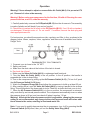
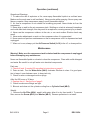
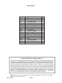
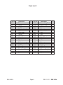
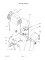
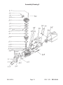
®
HOTDOG COMPRESSOR
4 GALLON - 2 HP
Model 45214
ASSEMBLY and OPERATING
INSTRUCTIONS
®
3491 Mission Oaks Blvd., Camarillo, CA 93011
Visit our Web site at http://www.harborfreight.com
Copyright © 2001 by Harbor Freight Tools®. All rights reserved. No portion of
this manual or any artwork contained herein may be reproduced in any shape or
form without the express written consent of Harbor Freight Tools.
For technical questions and replacement parts, please call 1-800-444-3353
Specifications
Motor Power
Electrical
NPT Air Outlet
Air Tank Size
Maximum PSI
Pressure Range
Air Delivery (cfm)
Pressure Disconnect
Pump Stage
Oil Requirement
2 HP, 3450 rpm
120V, 12 amps, 1400 watts, Single Phase, 60 Hz
1/4” NPT
3.5 Gallon
125 psi
Pressure Switch on at 80 psi, off at 110 psi
5 @ 40 psi / 4.5 @ 70 psi / 3.8 @ 90 psi / 3.0 @ 110 psi
Automatic at 170 psi
Single
Standard non-detegent, 30 weight compressor or motor oil
Optimal capacity for oil tank is 7.8 ounces.
Save This Manual
You will need the manual for the safety warnings and precautions, assembly instructions,
operating and maintenance procedures, parts list and diagram. Keep your invoice with this
manual. Write the invoice number on the inside of the front cover. Keep the manual and
invoice in a safe and dry place for future reference.
Safety Warnings and Precautions
WARNING: When using tool, basic safety precautions should always be followed to
reduce the risk of personal injury and damage to equipment.
Read all instructions before using this tool!
1.
Keep work area clean. Cluttered areas invite injuries.
2.
Observe work area conditions. Do not use machines or power tools in damp or wet
locations. Don’t expose to rain. Keep work area well lighted. Do not use electrically
powered tools in the presence of flammable gases or liquids.
3.
Keep children away. Children must never be allowed in the work area. Do not let
them handle machines, tools, or extension cords.
4.
Store idle equipment. When not in use, tools must be stored in a dry location to
inhibit rust. Always lock up tools and keep out of reach of children.
5.
Do not force tool. It will do the job better and more safely at the rate for which it was
intended. Do not use inappropriate attachments in an attempt to exceed the tool
capacity.
6.
Use the right tool for the job. Do not attempt to force a small tool or attachment to
do the work of a larger industrial tool. There are certain applications for which this tool
was designed. Do not modify this tool and do not use this tool for a purpose for which
it was not intended. Do not use to fill air/breathing tanks.
SKU 45214
Page 2
REV 02/04
7.
Dress properly. Do not wear loose clothing or jewelry as they can be caught in
moving parts. Protective, electrically non-conductive clothes and non-skid footwear
are recommended when working. Wear restrictive hair covering to contain long hair.
8.
Use eye and ear protection. Always wear ANSI approved impact safety goggles.
Wear a full face shield if you are producing metal filings or wood chips. Wear an ANSI
approved dust mask or respirator when working around metal, wood, and chemical
dusts and mists.
9.
Do not overreach. Keep proper footing and balance at all times. Do not reach over
or across running machines. Be careful not to trip on air hose.
10. Maintain tools with care. Keep tools clean for better and safer performance. Follow
instructions for lubricating and changing accessories. Inspect tool cords periodically
and, if damaged, have them repaired by an authorized technician. The handles must
be kept clean, dry, and free from oil and grease at all times.
11. Disconnect power. Unplug when not in use.
12. Remove adjusting keys and wrenches. Check that keys and adjusting wrenches
are removed from the tool or machine work surface before plugging it in.
13. Avoid unintentional starting. Be sure the switch is in the Off position when not in
use and before plugging in. Do not carry any tool with your finger on the trigger,
whether it is plugged in or not.
14. Stay alert. Watch what you are doing, use common sense. Do not operate any tool
when you are tired.
15. Check for damaged parts. Before using any tool, any part that appears damaged
should be carefully checked to determine that it will operate properly and perform its
intended function. Check for alignment and binding of moving parts; any broken parts
or mounting fixtures; and any other condition that may affect proper operation. Any
part that is damaged should be properly repaired or replaced by a qualified
technician. Do not use the tool if any switch does not turn On and Off properly.
16. Guard against electric shock. Prevent body contact with grounded surfaces such as
pipes, radiators, ranges, and refrigerator enclosures.
17. Replacement parts and accessories. When servicing, use only identical
replacement parts. Use of any other parts will void the warranty. Only use accessories
intended for use with this tool. Approved accessories are available from Harbor
Freight Tools.
18. Do not operate tool if under the influence of alcohol or drugs. Read warning
labels on prescriptions to determine if your judgment or reflexes are impaired while
taking drugs. If there is any doubt, do not operate the tool.
19. Use proper size and type extension cord. If an extension cord is required, it must
be of the proper size and type to supply the correct current to the tool without heating
up. Otherwise, the extension cord could melt and catch fire, or cause electrical
SKU 45214
Page 3
damage to the tool. This tool requires use of an extension cord of 0 to 10 amps
capability (up to 50 feet), with wire size rated at 18 AWG. Longer extension cords
require larger size wire. If you are using the tool outdoors, use an extension cord
rated for outdoor use. (signified by “WA” on the jacket).
20. Maintenance. For your safety, maintenance should be performed regularly by a
qualified technician.
21. Only use compressor with air. Never use with any other type of gas.
22. Powerful airstream. Never aim the compressor at humans or animals. Severe skin
damage may occur.
23. Transporting compressor. Use handle and wheels to move compressor. Never
move the compressor by pulling on the hoses. Never transport under pressure.
Release pressure in storage tank prior to moving.
Note: Your compressor comes with a grounded three-prong plug. If using an extension cord,
it must be a 3-prong type. Do not remove or disable the third prong (grounding prong).
Note: Performance of this tool (if powered by line voltage) may vary depending on
variations in local line voltage. Extension cord usage may also affect tool performance.
Warning: The warnings, cautions, and instructions discussed in this instruction manual
cannot cover all possible conditions and situations that may occur. It must be understood by the operator that common sense and caution are factors which cannot be
built into this product, but must be supplied by the operator.
Unpacking
When unpacking, check to make sure the parts listed on pages 7 and 8 are included. If any
parts are missing or broken, please call Harbor Freight Tools at the number on the cover of
this manual as soon as possible.
SKU 45214
Page 4
Operation
Warning!! Never attempt to adjust or remove Valve Air Outlet (#A-9). It is pre-set at 170
psi. Removal of valve voids warranty.
Warning!! Before using your compressor for the first time, fill with oil. Running the compressor with low, or no oil, voids the warranty.
1. Carefully and slowly unscrew the Oil Dipstick (#B-19) from the oil reservoir. The assembly
is made of plastic and will break if you are too forceful.
2. Check that oil reaches the full mark on the Oil Dipstick (#B-19). If not, fill with a standard,
non-detergent, 30-weight motor oil. Do not overfill. If overfilled, remove the drain plug and
drain appropriate amount.
For best service, you should incorporate an oiler, regulator, and filter, in line, as shown in the
diagram below. Hoses, couplers, oilers, regulators, and filters are all available from Harbor
Freight Tools.
Tool
1. Conncect your air hose to the 1/4” NPT.
2. Safety pre-check:
a. Make sure the drain valve at the bottom of the tank is closed.
b. Re-check the oil level.
c. Make sure the Valve Air Outlet (#A-9) is undamaged and functional.
3. Turn the Valve Air Outlet (#A-9) to the off position. In the off position, the handle is
perpendicular to the air hose fitting.
4. Turn on the compressor by pulling up the Air Pressure Switch (A-10). (To turn it off, push
the Air Pressure Switch (A-10) down.
5. Watch the Pressure Guage (#A-6) and allow the compressor to build up at least 80 psi.
6. After reaching 80 psi, open the Valve Air Outlet (#A-9) by turning it parallel to the air hose
fitting. This will pressurize the hoses and air tools. Check for air leaks and test your air tool.
7. When the Air Pressure Switch(A-10) is in the on position, the compressor is automatically controlled by an internal pressure switch. The compressor automatically turns on when
the pressure drops to 80 psi, and turns back off when it reaches 110 psi.
Warning! Although the internal pressure switch is adjustable, changing the pressure
setting is not recommended; any change to the on/off pressure levels will cause additional stress to the motor, resulting in shortened motor life.
Note: If you need to quickly depressurize the air compressor, turn it off by pressing the Air
Pressure Switch (A-10) down, then, pull out the Safety Valve Ring (#A-4).
SKU 45214
Page 5
REV 02/04
Operation (continued)
Operational Warnings:
1. To reduce the risk of explosion or fire, never spray flammable liquids in a confined area.
Make sure the work area is well ventilated. Never smoke while spraying. Never spray near
flames or sparks. Keep compressor away from all flammable objects.
2. Air from a compressor is not suitable for breathing purposes. Never inhale air from the
compressor.
3. Never alter or weld on the air compressor tank. Welding on a tank is extremely hazardous
and could affect tank strength; this may result in an explosion, causing severe injury or death.
4. Never use the compressor outdoors in the rain, or on a wet surface. Electric shock may
result.
5. Never make adjustments or work on the compressor when it is pressurized.
6. Never service or perform maintenance on the air compressor until it is depressurized and
unplugged.
7. When not in use, always put the Air Pressure Switch (A-10) in the off, or down position.
Maintenance
Warning! Make sure the compressor tank is drained and the compressor is unplugged
before attempting any maintenance.
Never use flammable liquids or solvents to clean the compressor. Clean with a mild detergent
and water. Be careful to not spill water onto electrical components.
Each use.
1. Check oil level. If needed, fill according to instructions on page 5.
2. Drain air tank. Turn the Water Valve (#A-5) clockwise. Reverse to close. It is good practice to leave it open between uses, to keep tank dry.
3. Check for worn or damaged cords or plugs.
After first 50 hours or 30 days.
1. Replace the oil. See the top of page 5.
2. Check to make sure fittings are tight.
3. Blow air and clean out the cylinder cooling fins on Cylinder Head (#B-5).
Weekly.
1. Remove the Air Filter (#B-4), wash it with water, allow it to dry, then install it. To remove
filter, remove the Screw (#B-2) and Washer (#B-3). Reverse procedure to re-install.
SKU 45214
Page 6
REV 02/04
Parts List 1
Part No.
A-1
A-2
A-3
A-4
A-5
A-6
A-7
A-8
A-9
A-10
A-11
A-12
A-13
A-14
A-15
A-16
A-17
Description
Wheel
Pin
One Way Valve
Safety Valve Ring
Water Valve
Pressure Guage
Non-return valve
PVC Tube
Valve Air Outlet
Air Pressure Switch
Cord and Plug
Pipe
Nut
Bolt
Tank and Handle
Rubber Foot
Axle
Qty.
2
2
1
1
1
1
1
1
1
1
1
1
2
2
1
2
1
PLEASE READ THE FOLLOWING CAREFULLY
THE MANUFACTURER AND/OR DISTRIBUTOR HAS PROVIDED THE PARTS DIAGRAM IN THIS
MANUAL AS A REFERENCE TOOL ONLY. NEITHER THE MANUFACTURER NOR DISTRIBUTOR MAKES ANY REPRESENTATION OR WARRANTY OF ANY KIND TO THE BUYER THAT HE
OR SHE IS QUALIFIED TO MAKE ANY REPAIRS TO THE PRODUCT OR THAT HE OR SHE IS
QUALIFIED TO REPLACE ANY PARTS OF THE PRODUCT. IN FACT, THE MANUFACTURER
AND/OR DISTRIBUTOR EXPRESSLY STATES THAT ALL REPAIRS AND PARTS REPLACEMENTS
SHOULD BE UNDERTAKEN BY CERTIFIED AND LICENSED TECHNICIANS AND NOT BY THE
BUYER. THE BUYER ASSUMES ALL RISK AND LIABILITY ARISING OUT OF HIS OR HER
REPAIRS TO THE ORIGINAL PRODUCT OR REPLACEMENT PARTS THERETO, OR ARISING
OUT OF HIS OR HER INSTALLATION OF REPLACEMENT PARTS THERETO.
NOTE: Some parts are listed and shown for illustration purposes only and are not available
individually as replacement parts.
SKU 45214
Page 7
Parts List 2
Part No.
B-1
B-2
B-3
B-4
B-5
B-6
B-7
B-8
B-9
B-10
B-11
B-12
B-13
B-14
B-15
B-16
B-17
B-18
B-19
B-20
SKU 45214
Description
Qty.
Bolt
4
Screw
2
Washer
2
Air Filter
1
Cylinder Head
1
Gasket
1
Valve Seat
1
Gasket
1
Valve Plate
1
Valve Seat
1
Gasket
1
Cylinder
1
Gasket
1
Compression Ring 2
Oil Ring
1
Piston
1
Piston Pin
1
Crankshaft Retainer 2
Dipstick
1
Screw
1
Part No.
B-21
B-22
B-23
B-24
B-25
B-26
B-27
B-28
B-29
B-30
B-31
B-32
B-33
B-34
B-35
B-36
B-37
B-38
B-39
B-40
Page 8
Description
Connecting Rod
Front Cover
Washer
Screw
Gasket
Crankshaft
Nut
Bolt
Cover
Fan Wheel
Washer
Motor
Screw
Capacitor
Bearing
Oil Seal
Nut
Thermal Switch
Crankshaft Case
Washer
REV 11/01
Qty.
1
1
4
4
1
1
4
4
1
1
4
1
4
2
1
1
2
1
1
4
REV 02/04
Assembly Drawing 1
SKU 45214
Page 9
Assembly Drawing 2
SKU 45214
Page 10
REV 11/01
REV 02/04