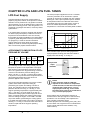
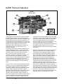
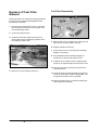
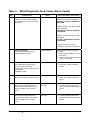
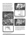
1
SB4136E00
Jun. 2004
Service Manual
G420E/G424E Tier
Lift Trucks
LP Engine
G15S-2, G18S-2, G20SC-2
GC15S-2, GC18S-2, GC20SC-2
With G420E Tier LP Engine
G20E-3, G25E-3, G30E-3, G32E-3
GC20E-3, GC25E-3, GC30E-3, GC32E-3
with G424E Tier LP Engine
Important Safety Information
Most accidents involving product operation, maintenance and repair are caused by failure to observe basic safety
rules or precautions. An accident can often be avoided by recognizing potentially hazardous situations before an
accident occurs. A person must be alert to potential hazards. This person should also have the necessary training,
skills and tools to perform these functions properly.
Read and understand all safety precautions and warnings before operating or performing lubrication,
maintenance and repair on this product.
Basic safety precautions are listed in the “Safety” section of the Service or Technical Manual. Additional safety
precautions are listed in the “Safety” section of the owner/operation/maintenance publication.
Specific safety warnings for all these publications are provided in the description of operations where hazards exist.
WARNING labels have also been put on the product to provide instructions and to identify specific hazards. If
these hazard warnings are not heeded, bodily injury or death could occur to you or other persons. Warnings in this
publication and on the product labels are identified by the following symbol.
WARNING
Improper operation, lubrication, maintenance or repair of this product can be dangerous and could result
in injury or death.
Do not operate or perform any lubrication, maintenance or repair on this product, until you have read and
understood the operation, lubrication, maintenance and repair information.
Operations that may cause product damage are identified by NOTICE labels on the product and in this publication.
DAEWOO cannot anticipate every possible circumstance that might involve a potential hazard. The warnings in
this publication and on the product are therefore not all inclusive. If a tool, procedure, work method or operating
technique not specifically recommended by DAEWOO is used, you must satisfy yourself that it is safe for you and
others. You should also ensure that the product will not be damaged or made unsafe by the operation, lubrication,
maintenance or repair procedures you choose.
The information, specifications, and illustrations in this publication are on the basis of information available at the
time it was written. The specifications, torques, pressures, measurements, adjustments, illustrations, and other
items can change at any time. These changes can affect the service given to the product. Obtain the complete and
most current information before starting any job. DAEWOO dealers have the most current information available.
1
WARNING
Read this entire manual and all other publications pertaining to the work to be performed before installing,
operating, or servicing this equipment. Practice all plant and safety instructions and precautions. Failure to follow
instructions can cause personal injury and/or property damage.
The engine or other type of prime mover should be equipped with an over speed (over temperature, or
overpressure, where applicable) shutdown device(s), that operates totally independently of the prime mover
control device(s) to protect against runaway or damage to the engine or other type of prime mover with possible
personal injury or loss of life should the mechanical-hydraulic governor(s) or electric control(s), the actuator(s), fuel
control(s), the driving mechanism(s), the linkage(s), or the controlled device(s) fail.
CAUTION
To prevent damage to a control system that uses an alternator or battery-charging device, make sure the charging
device is turned off before disconnecting the battery from the system. Electronic controls contain static-sensitive
parts. Observe the following precautions to prevent damage to these parts.
z Discharge body static before handling the control (with power to the control turned off, contact a grounded
surface and maintain contact while handling the control).
z Avoid all plastic, vinyl, and Styrofoam (except antistatic versions) around printed circuit boards.
z Do not touch the components or conductors on a printed circuit board with your hands or with conductive
devices.
IMPORTANT DEFINITIONS
WARNING—indicates a potentially hazardous situation, which, if not avoided, could result in death or
serious injury.
CAUTION—indicates a potentially hazardous situation, which, if not avoided, could result in damage to
equipment.
NOTE—provides other helpful information that does not fall under the warning or caution categories.
* This manual shows just LP fuel and engine control system for TIER- LP engine, so regarding
other ares(basic engine), please refer to the separate manual of SB4008E for G420 and SB2215E for
G424.
G420E/G424E Tier
LP Engine
3
Table of Contents
Index
CHAPTER 3 MI- 04 MAINTENANCE
SCHEDULE
WORKING WITH LPG EQUIPMENT
RECOMMENDED MAINTENANCE SCHEDULE.....30
Test Fuel System for Leaks ......................................30
Inspect Engine for Fluid Leaks .................................30
Inspect Vacuum Lines and Fittings...........................30
Inspect Electrical System .........................................30
Inspect Acceleration Pedal Operation ......................31
Check Coolant Level ................................................31
Inspect Coolant Hoses .............................................31
Inspect Battery System ............................................31
Inspect Ignition System ............................................31
Replace Spark Plugs ................................................31
Replace LP Fuel Filter Element................................32
Testing Fuel Lock-off Operation................................33
Pressure Regulator/Converter Testing and
nspection ..................................................................33
Fuel Trim Valve Inspection (FTV) .............................33
Inspect Air/Fuel Valve Mixer Assembly.....................33
Inspect for Intake Leaks ...........................................34
Inspect Throttle Assembly ........................................34
Checking the TMAP Sensor .....................................34
Inspect Engine for Exhaust Leaks............................34
Replace Oxygen Sensor ..........................................34
Maintenance Schedule.............................................35
CHAPTER 0 LPG AND LPG FUEL TANKS
LPG Fuel Supply........................................................8
LPG Fuel Tanks..........................................................9
Installing LPG Fuel Tanks ..........................................9
LPG Fuel Tank Components ....................................10
Fuel Gauge ..............................................................10
Service Valve ...........................................................10
Quick Disconnect Coupling...................................... 11
Filler Valve................................................................ 11
CHAPTER 1 ENGINE SPECIFICATION
Indication of Engine Serial Number..........................12
Specifications(G420E) .............................................13
Specifications(G424E) .............................................14
CHAPTER 2 MI-04 LPG SYSTEM
OPERATIONAL OVERVIEW
MI-04 General Description .......................................15
MI-04 LP Fuel Filter..................................................17
MI-04 Fuel Lock-Off (Electric) ..................................17
MI-04 N-2001 Regulator/Converter..........................18
N-2001 Theory of Operation ....................................19
MI-04 N-CA55-500TR Mixer ....................................20
N-CA55-500-TR Air/Fuel Mixer Theory of
Operation .................................................................20
MI-04 Electronic Throttle..........................................22
MI-04 Fuel Trim Valve ..............................................23
Heated Exhaust Gas Oxygen Sensor (HEGO) ........24
MI-04 SECM (General Description) .........................25
MI-04 SECM (Fuel Management) ............................25
MI-04 SECM (Load/Speed Management)................27
MI-04 Ignition management .....................................29
CHAPTER 4 MI-04 LP BASIC
TROUBLESHOOTING
Basic Troubleshooting ..............................................37
CHAPTER 5 MI-04 LP ADVANCED
DIAGNOSTICS
Advanced Diagnostics..............................................44
Reading Diagnostic Fault Codes..............................44
Displaying Fault Codes (DFC) From SECM
Memory ....................................................................45
Clearing Fault (DFC) Codes.....................................45
Fault Action Descriptions..........................................45
Fault List Definitions .................................................46
Table a. MI-04 Diagnostic Fault Codes (Flash
Codes)......................................................................48
CHAPTER 6 MI-04 ELECTRICAL
CONNECTIONS
Resistance Checks...................................................62
Voltage Checks.........................................................63
G420E/G424E Tier
LP Engine
5
Table of Contents
CHAPTER 7 N2001 PRESSURE
REGULATOR /CONVERTER
Removal and Installation of N2001 LP
Regulator/Converter.................................................64
Hose Connections....................................................65
N2001 Removal Steps: ............................................66
N2001 Regulator Disassembly Steps:......................67
N2001 Disassembled Service..................................69
CHAPTER 8 N-CA55-500TR AIR/FUEL
MIXER
Removal and Installation of the N-CA55-500TR
Mixer ........................................................................70
N-CA55-500TR Mixer Removal Steps: ....................71
N-CA55-500TR Disassembly and Service...............72
N-CA55-500TR Disassembled Service....................74
Installing the Mixer/Throttle Assembly......................75
CHAPTER 9 TEST AND ADJUSTMENTS
N2001 Service Testing .............................................78
Primary Stage Test Hardware ..................................79
Primary Stage Pressure Test....................................79
N-CA55-500TR Service AVV (Air Valve Vacuum)
Testing......................................................................81
Ignition Timing Adjustment .......................................82
Idle Mixture Adjustment............................................85
CHAPTER 10 SERVICE TOOL KIT
Service Tool Kit ........................................................87
G420E/G424E Tier
LP Engine
6
Table of Contents
WORKING WITH LPG
EQUIPMENT
NOTE
NFPA (National Fire Protection Agency) 58 covers the
procedures for storage and garaging for repair
purposes, on propane powered equipment.
WARNING
CAUTION
Propane Vapor is heavier than air and can collect in
low areas when adequate ventilation or air movement
is not present to disperse it. Never check for leaks
with a flame or match. Use a leak detector solution or
an electronic detector. Make sure the container
service valve is closed when connecting or
disconnecting. If the container service valve does not
operate properly, discontinue use and contact your
propane supplier. Never insert any object into the
pressure relief valve.
Safety is an important consideration for any repair
facility, and repairing LPG fueled machinery is no
exception. Refer to the NFPA (National Fire
Protection Agency) for the appropriate fire
extinguisher specifications and fluorescent lighting
requirements.
Propane has a heavier than air vapor density and will
fall if a leak occurs, while natural gas, by comparison,
will rise in the event of a leak (Figure 1).
This is an important property that technicians need to
be aware of when performing maintenance. When
repairing propane machinery, the work should be
performed in the lowest point of the facility where
possible. The tank supply should be shut off, except
when required for running equipment.
WARNING
LP gas is highly flammable. To prevent personal injury,
keep fire and flammable materials away from the lift
truck when work is done on the fuel system.
Gas vapor may reduce oxygen available for breathing,
cause headache, nausea, dizziness and
unconsciousness and lead to injury or death. Always
operate the forklift in a well ventilated area
Liquid propane may cause freezing of tissue or
frostbite. Avoid direct contact with skin or tissue;
always wear appropriate safety protection including
gloves and safety glasses when working with liquid
propane.
Diesel
CAUTION
CNG
Figure 1
The regulator/converter and mixer are part of a
certified system complying with EPA and CARB 2004
requirements. Only trained certified technicians
should perform disassemble, service or replacement
of the regulator/converter or mixer.
LPG
CAUTION
LPG fueled machinery may be garaged anywhere
gasoline powered vehicles are garaged. When
machines are stored for a long period, it is advisable
to shut off the tank supply valve and run the machine
until the fuel trapped down stream of the valve is
depleted.
G420E/G424E Tier
LP Engine
7
Working with LPG Equipment
CHAPTER 0 LPG AND LPG FUEL TANKS
The same principle is applied to LPG in a container,
commonly referred to as an LPG tank or cylinder.
Typically an LPG tank is not filled over 80% capacity
allowing for a 20% vapor expansion space. Outside
air temperature effect’s an LPG tank and must be
considered when using an LPG system. (Figure 2)
shows the relationship between pressure and
temperature in a LPG tank at a steady state condition.
LPG Fuel Supply
Liquefied petroleum gas (LPG) consists mainly of
propane, propylene, butane, and butylenes in various
mixtures. LPG is produced as a by-product of natural
gas processing or it can be obtained from crude oil as
part of the oil refining process. LPG, like gasoline, is a
compound of hydrogen and carbon, commonly called
hydrocarbons.
LPG Tank Pressure VS Temperature
In its natural state, propane is colorless and odorless;
an odorant (ethyl mercaptan) is added to the fuel so
its presence can be detected. There are currently
three grades of propane available in the United States.
A propane grade designation of HD5 (not exceeding
5% propylene), is used for internal combustion
engines while much higher levels of propylene
(HD10) are used as commercial grade propane along
with a commercial propane /butane mixture.
300
Pressure, psig
250
200
150
100
50
0
-20
0
Figure 2
APPROXIMATE COMPOSITION OF HD5
PROPANE BY VOLUME
Propane
Propy
Butane
Iso-
Methane
(C3H8)
lene
(C4H10)
Butane
(CH4)
5% max.
2.0%
1.5%
1.5%
90.0%
min.
60
80
100
120
140
TOTAL
100%
Compressed
Vapor
128 PSIG
Liquid
Propane
LPG Tank
Figure 3
NOTE
Vapor pressure inside an LPG tank
depends on the ambient air temperature
outside the tank, not the amount of liquid
inside the tank. A tank that is ¾ full of
liquid propane at 80 deg. F will contain
the same vapor pressure as a tank that is
only ¼ full of liquid propane.
This process operates similarly to an engine coolant
system where water is kept from boiling by
pressurizing the system and adding a mixture of
glycol. For example water at normal atmospheric
pressure will boil at 212 deg. F / 100 deg. C. If an
engines operating temperature is approximately 230
deg. F / 110 deg. C, then the water in an open unpressurized cooling system would simply boil off into
steam, eventually leaving the cooling system empty
and over heating the engine. If we install a 10 PSIG
cap on the radiator, pressurizing the cooling system
to 10 PSIG, the boiling point of the water increases to
242 deg. F / 117 deg. C, which will cause the water to
remain in liquid state at the engines operating
temperature.
LP Engine
40
Temperature, deg F
With 128 PSIG vapor pressure acting against the
liquid propane the boiling point has been raised to
slightly more than 80 deg. F / 27 deg. C.
An advantage of LPG is the ability to safely store and
transport the product in the liquid state. In the liquid
state propane is approximately 270 times as dense
as it is in a gaseous form. By pressurizing a container
of LPG we can effectively raise the boiling point
above –44 deg. C / -42 deg. C, keeping the propane
in liquid form. The point at which the liquid becomes a
gas (boiling point) depends on the amount of
pressure applied to the container.
G420E/G424E Tier
20
LPG’s relative ease of vaporization makes it an
excellent fuel for low-rpm engines on start-and-stop
operations. The more readily a fuel vaporizes the
more complete combustion will be.
Because propane has a low boiling point (-44F), and
is a low carbon fuel, engine life can be extended due
to less cylinder wall wash down and little, if any,
carbon build up.
8
LPG and LPG Fuel Tanks
LPG Fuel Tanks
Installing LPG Fuel Tanks
The two styles of LPG storage containers available
for industrial use and lift truck applications are
portable universal cylinders and permanently
mounted tanks. Portable universal cylinders are used
primarily for off-highway vehicles and are constructed
in accordance with the DOT-TC (United States
Department of Transport – Transport Canada). The
cylinders are referred to as universal because they
can be mounted in either a vertical or horizontal
position (Figure 4).
When installing a tank on a lift truck, the tank must be
within the outline of the vehicle to prevent damage to
the valves when maneuvering in tight spaces.
Horizontal tanks must be installed on the saddle that
contains an alignment pin, which matches the hole in
the collar of the tank. When the pin is in the hole, the
liquid withdrawal tube is positioned to the bottom of
the tank. A common problem is that often these
guide-pins are broken off, allowing the tank to be
mounted in any position. This creates two problems.
1). When the liquid withdrawal tube is exposed to the
vapor space, it may give a false indication that the
tank is empty, when it actually is not. 2). The safety
relief valve may be immersed in liquid fuel. If for any
reason the valve has to vent, venting liquid can cause
a serious safety problem,
CAUTION
When empty, the tank is exchanged with a
pre-filled replacement tank. When
exchanging a tank, safety glasses and
gloves should be worn.
Figure 4
NOTE
A 375-psig, relief valve is used on a DOT
forklift tank. The relief valve must be
replaced with a new valve after the first 12
years and every 10 years thereafter.
The tank must be discarded if the collar is damaged
to the point that it can no longer protect the valves. It
must also be replaced if the foot ring is bent to the
point where the tank will not stand or is easily
knocked over.
G420E/G424E Tier
LP Engine
9
LPG and LPG Fuel Tanks
LPG Fuel Tank Components
2
3
7 8
Service Valve
The service valve is a manually operated valve using
a small hand wheel to open and close the fuel supply
to the service line (fuel supply line). The service valve
installs directly into the tank and has two main
categories, liquid and vapor service valves. Liquid
service valves used on portable LPG tanks use a 3/8”
(3/8” NPT) male pipe thread on the service valve
outlet for attachment of a quick disconnect coupler.
9
1
4
6
5
12
11
An excess flow valve is built into the inlet side of the
service valve as a safety device in case of an
accidental opening of the service line or damage to
the service valve itself. The excess flow valve shuts
off the flow of liquid propane if the flow rate of the
liquid propane exceeds the maximum flow rate
specified by the manufacturer.
10
Figure 5
(1) Fuel Gauge (2) 80% Stop Bleeder
(3) Pressure Relief Valve
(4) Service Valve (Tank end male coupling) (5) Filler Valve
(6) Alignment Pin
(7) Vapor Withdrawal Tube (Only used with Vapor Withdrawal)
(8) 80% Limiter Tube (9) Liquid Withdrawal Tube
(10) Foot Ring (11) Fuel Level Float (12) Collar
Fuel Gauge
Outlet
In figure 5 a visual fuel gauge is used to show the fuel
level in the tank. A mechanical float mechanism
detects the liquid propane level. A magnet on the end
of the float shaft moves a magnetic pointer in the fuel
gauge. Some units have an electronic sending unit
using a variable resistor, installed in place of a gauge
for remote monitoring of the fuel level. The gauge
may be changed with fuel in the tank. DO NOT
REMOVE THE FOUR LARGE FLANGE BOLTS
THAT RETAIN THE FLOAT ASSEMBLY, WITH
FUEL IN THE TANK!
Excess Flow
Valve
Figure 6
CAUTION
When the tank is in use the service valve
should be completely open. If the valve is
partly open, the vehicle may not be
getting enough fuel to operate efficiently.
WARNING
It is not a legal practice to fill the tank
through the liquid contents gauge.
In addition to possibly starving the engine for fuel,
a partly open valve may restrict the flow enough
to prevent the excess flow valve from closing in
the event of a ruptured fuel line.
In some applications a fixed tube fuel indicator is
used in place of a float mechanism. A fixed tube
indicator does not use a gauge and only indicates
when the LPG tank is 80% full. The fixed tube
indicator is simply a normally closed valve that is
opened during refueling by the fueling attendant.
When opened during refueling and the tanks LPG
level is below 80%, a small amount of vapor will exit
the valve. When the LPG tank level reaches 80%
liquid propane will begin exiting the valve in the form
of a white mist (Always wear the appropriate
protective apparel when refueling LPG cylinders). In
order for this type of gauge to be accurate, the tank
must be positioned properly. When full (80% LPG)
the valve is closed by turning the knurled knob
clockwise. Typically a warning label surrounds the
fixed tube gauge which reads STOP FILLING WHEN
LIQUID APPEARS.
G420E/G424E Tier
LP Engine
Most liquid service valves have an internal hydrostatic
relief valve and are usually labeled “LIQUID WITH
INTERNAL RELIEF”. The hydrostatic relief valve
protects the fuel service line between the tank and
the lock off from over pressurization. The internal
hydrostatic relief valve has a minimum opening
pressure of 375 PSIG and a maximum pressure of
500 PSIG. These type of relief valves have an
advantage over external relief valves because the
propane is returned to the tank in the event of an over
pressurization instead of venting the propane to
atmosphere.
10
LPG and LPG Fuel Tanks
Quick Disconnect Coupling
Filler Valve
The liquid withdrawal or service valve on a DOT tank
has male threads and accepts the female portion of a
quick disconnect coupling (Figure 8). The female
portion is adapted to the liquid hose going to the fuel
system. Both halves are equipped with 100% shutoffs,
which open when coupled together to allow fuel flow.
The coupler has two seals. One is an o-ring and the
other is a flat washer. The o-ring prevents leakage
from the shaft on the other coupling and the flat
washer seals when the coupler is fully connected.
The liquid filler valve (Figure 9) has a male thread to
receive a fuel nozzle and typically has a plastic or
brass screw on cap that is retained with a small chain
or plastic band to keep debris out of the filler valve.
The filler valve is a one-way flow device that uses two
check valves to allow fuel to enter the tank but
prevent it from exiting. Both check valves are
backpressure type check valves, designed so that
backpressure from the tank assists the check valves
own spring pressure to close the valve. The first valve
uses a neoprene on metal seal and the second valve
uses a metal on metal seal.
NOTE
The flat seal and/or the o-ring will
sometimes pop off when disconnecting
and slide up the shaft of the mating
connector, causing the valve not to open
when fully mated. The extra washer or oring must be removed from the shaft and
the coupling reconnected.
A weakness ring is machined into the filler valve just
above the check valves and will allow the filler valve
to shear off in case of an accident. The valve will
break or shear off above the check valves so that the
tank will be sealed and no liquid propane can escape.
Weakness
Ring
Figure 9
Figure 8
G420E/G424E Tier
LP Engine
11
MI-04 System Overview
CHAPTER 1 ENGINE SPECIFICATION
Indication of Engine Serial Number
G420E/G424E Tier
LP Engine
12
Engine Specification
Specifications(G420E)
GENERAL DESCRIPTION
ENGINE TYPE:
COMBUSTION SYSTEM:
EXHAUST SYSTEM:
VALVE CONFIGURATION:
DISPLACEMENT:
BORE:
STROKE:
COMPRESSION RATIO:
COMPRESSION PRESSURE:
VALVE TIMING:
FIRING ORDER:
SPARK PLUGS:
WEIGHT:
ROTATION:
FUELTYPE:
GOVERNED SPEED:
IDLE RPM:
IGNITIOIN TIMING:
Water-cooled, Inline 4-Cycle, 4-Cylinders
Naturally Aspirated 1-Venturi Intake Manifold
Semi-spherical Combustion chamber
Cast Iron, Dry
OHC, 2 Valves per Cylinder
1,997 cc (122 CID)
85 mm (3.35 in.)
88 mm (3.46 in.)
8.5:1
1,128 kPa (163.5 psi)
Intake Valve: 12° BTDC(Open)/ 40° ABDC(Close)
Exhaust Valve: 54° BBDC(Open)/ 6° ATDC(Close)
1-3-4-2
BPR5ES: 0.7-0.8 mm (0.028-0.031 in.) Air Gap
139 Kg (306 lbs.), Dry
Counter-Clockwise (CCW) when viewed from Flywheel End
LPG
2400 +/- 25 RPM
700 +/- 25 RPM
Electronic controlled by ECM
LP FUEL SYSTEM
MIXER:
REGULATOR:
FUEL FILTRATION:
Piston Type Air Valve Assembly inside, Downdraft
Two-Stage Negative Pressure Regulator
40 Microns Maximum
COOLING SYSTEM
WATER PUMP ROTATION:
THERMOSTAT:
COOLING WATER CAPACITY
V-Belt Drive - Clockwise (CW) when viewed from engine front
Opening Temperature: 82°C (180°F)
Fully Open Temperature: 95°C (203°F)
3.1 L (block only)
LUBRICATION SYSTEM
OIL PRESSURE:
OIL TEMPERATURE:
CRANKCASE CAPACITY:
OIL FILTER:
ENGINE OIL SPECIFICATION:
450 kPa (65 psi) @ Hi Idle
50 kPa (7 psi) @ Low Idle
Upper Limit: 125°C (257°F)
Recommended: 99 - 110°C (210 - 230°F)
Lower Limit: 80°C (176°F)
3.7 L
0.3 L
API - SJ, SAE 10W30 or SAE 5W30
ENGINE ELECTRICAL
IGNITION TYPE:
IGNITION COIL:
DISTRIBUTOR:
STARTER MOTOR:
ALTERNATOR:
ENGINE OIL PR. S/W:
ENGINE CONTROL MODULE(ECM):
VR SENSOR:
TMAP:
PEDAL ANGLE SENSOR:
ECT-ECM:
Electronic Advanced by ECM
12 V operation volt, Ignition driver circuitry inside
Mitsubishi Distributor
12 Volt, 1.2 kW, Reduction drive
12 Volt, 61 Amp
24.5 kPa (3.6 psi)
12 V operation volt, 24 pins of I/O
Magnetic pick up sensor
Intake Air Temp. & Manifold Absolute Press. Sensor
Two-Output Signals (Installed on Accelerator Pedal)
Heated Exhaust Gas Oxygen Sensor (HEGO)
12 V operation volt
Engine Coolant Temperature Sensor for ECM
ECT-GAUGE
TPS:
THROTTLE BODY:
FUEL TRIM VALVE (FTV):
LP FUEL LOCK-OFF:
Engine Coolant Temp. Sensor for GAUGE on Instrument Panel
Throttle Position Sensor (built in Throttle Body)
Electronic Throttle Body
12 V operation volt
12 V operation volt, ON/OFF Control by ECM
OXYGEN SENSOR:
EXHAUST SYSTEM
CATALYTIC MUFFLER:
G420E/G424E Tier
Three-way Catalyst included
LP Engine
13
Engine Specification
Specifications(G424E)
GENERAL DESCRIPTION
ENGINE TYPE:
COMBUSTION SYSTEM:
EXHAUST SYSTEM:
VALVE CONFIGURATION:
DISPLACEMENT:
BORE:
STROKE:
COMPRESSION RATIO:
COMPRESSION PRESSURE:
VALVE TIMING:
FIRING ORDER:
SPARK PLUGS:
WEIGHT:
ROTATION:
FUELTYPE:
GOVERNED SPEED:
IDLE RPM:
IGNITIOIN TIMING:
Water-cooled, Inline 4-Cycle, 4-Cylinders
Naturally Aspirated 1-Venturi Intake Manifold
Semi-spherical Combustion chamber
Cast Iron, Dry
OHC, 2 Valves per Cylinder
2,350 cc (143 CID)
86.5 mm (3.41 in.)
100 mm (3.94 in.)
8.6:1
1,128 kPa (163.5 psi)
Intake Valve: 12° BTDC(Open)/ 40° ABDC(Close)
Exhaust Valve: 54° BBDC(Open)/ 6° ATDC(Close)
1-3-4-2
BPR5ES: 0.7-0.8 mm (0.028-0.031 in.) Air Gap
146 Kg (322 lbs.), Dry
Counter-Clockwise (CCW) when viewed from Flywheel End
LPG
2600 +/- 25 RPM
700 +/- 25 RPM
Electronic controlled by ECM
LP FUEL SYSTEM
MIXER:
REGULATOR:
FUEL FILTRATION:
Piston Type Air Valve Assembly inside, Downdraft
Two-Stage Negative Pressure Regulator
40 Microns Maximum
COOLING SYSTEM
WATER PUMP ROTATION:
THERMOSTAT:
COOLING WATER CAPACITY:
V-Belt Drive - Clockwise (CW) when viewed from engine front
Opening Temperature: 82°C (180°F)
Fully Open Temperature: 95°C (203°F)
3.1 L (block only)
LUBRICATION SYSTEM
OIL PRESSURE:
OIL TEMPERATURE:
CRANKCASE CAPACITY:
OIL FILTER:
ENGINE OIL SPECIFICATION:
50 kPa (7 psi) @ Low Idle 450 kPa (65 psi) @ Hi Idle
Upper Limit:
125°C (257°F)
Recommended:
99 - 110°C (210 - 230°F)
Lower Limit:
80°C (176°F)
3.7 L
0.3 L
API - SJ, SAE 10W30 or SAE 5W30
ENGINE ELECTRICAL
IGNITION TYPE:
IGNITION COIL:
DISTRIBUTOR:
STARTER MOTOR:
ALTERNATOR:
ENGINE OIL PR. S/W:
ENGINE CONTROL MODULE(ECM):
VR SENSOR:
TMAP:
PEDAL ANGLE SENSOR:
OXYGEN SENSOR:
ECT-ECM:
ECT-GAUGE
TPS:
THROTTLE BODY:
FUEL TRIM VALVE (FTV):
LP FUEL LOCK-OFF:
Electronic Advanced by ECM
12 V operation volt, Ignition driver circuitry inside
Mitsubishi Distributor
12 Volt, 1.2 kW, Reduction drive
12 Volt, 61 Amp
24.5 kPa (3.6 psi)
12 V operation volt, 24 pins of I/O
Magnetic pick up sensor
Intake Air Temp. & Manifold Absolute Press. Sensor
Two-Output Signals (Installed on Accelerator Pedal)
Heated Exhaust Gas Oxygen Sensor (HEGO) 12 V operation volt
Engine Coolant Temperature Sensor for ECM
Engine Coolant Temp. Sensor for GAUGE on Instrument Panel
Throttle Position Sensor (built in Throttle Body)
Electronic Throttle Body
12 V operation volt
12 V operation volt, ON/OFF Control by ECM
EXHAUST SYSTEM
CATALYTIC MUFFLER:
G420E/G424E Tier
Three-way Catalyst included
LP Engine
14
Engine Specification
CHAPTER 2 MI-04 LPG SYSTEM OPERATIONAL
OVERVIEW
MI-04 General Description
MI-04 control system is designed to provide a complete, fully integrated solution that will meet or exceed TIER-2
Large Spark Ignited Engines emission standards established by the California Air Research Board (CARB) and the
Environmental Protection Agency (EPA) for 2004. The MI-04 is a closed loop system utilizing a catalytic muffler to
reduce the emission level in the exhaust gas. In order to obtain maximum effect from the catalyst, an accurate
control of the air fuel ratio is required. A small engine control module (SECM) uses a heated exhaust gas oxygen
sensor (HEGO) in the exhaust system to monitor exhaust gas content.
MI-04 System with the N-CA55-500 Mixer
Fuel Filter
Fault Light
LP Fuel Line
Key switch
Accel Pedal
APP
Fuel Lock
Main
PWR
Relay
Vacuum Line
Air Cleaner
Converter
Fuel Trim Valve
Coolant Line
Mixer
DBW Throttle
TMAP
Oxygen
Engine
Catalytic
Muffler
TPS
SECM
Distributor
VR Sensor
Coolant Temp Sensor
Figure 10
G420E/G424E Tier
LP Engine
15
System Operational Overview
The SECM makes any necessary corrections to the air fuel ratio by controlling the inlet fuel pressure to the air/fuel
mixer by modulating the fuel trim valve (FTV) connected to the regulator. Reducing the fuel pressure leans the
air/fuel mixture and increasing the fuel pressure enriches the air/fuel mixture. To calculate any necessary
corrections to the air fuel ratio, the SECM uses a number of different sensors to gain information about the engines
performance. Engine speed is monitored by the SECM through a variable reluctance (VR) sensor. Intake manifold
air temperature and absolute pressure is monitored with a (TMAP) sensor. The MI-04 is a drive by wire (DBW)
system connecting the accelerator pedal to the electronic throttle through the electrical harness, mechanical
cables are not used. A throttle position sensor (TPS) monitors throttle position in relation to the accelerator pedal
position sensor (APP) feedback. Even engine coolant temperature is monitored by the SECM. The SECM
controller has full adaptive learning capabilities, allowing it to adapt control function as operating conditions change.
Factors such as ambient temperature, fuel variations, ignition component wear, clogged air filter, and other
operating variables are compensated.
Open Loop LP Fuel System
Fuel
Lock-Off
LP
Converter
LP
Mixer
Governor
Engine
Muffler
G420/G424 Open Loop LP Fuel System
MI-04 Closed Loop LP Fuel System
VR
Sensor
Coolant
Sensor
Small
Engine
Control
Module
(SECM)
TMAP
Sensor
Acceleration
pedal
Angle
Sensor
Fuel
Lock-Off
Oxygen
Sensor
LP
Converter
Fuel Trim
Valve
Smart Coil
LP
Mixer
Electronic
Throttle
Engine
Catalytic
Muffler
G420E/G424E Closed Loop LP Fuel System
G420E/G424E Tier
LP Engine
16
System Operational Overview
MI-04 LP Fuel Filter
MI-04 Fuel Lock-Off (Electric)
Figure 11
Figure 12
The fuel lock-off is a safety shutoff valve, normally
held closed by spring pressure, which is operated by
an electric solenoid and prevents fuel flow to the
regulator/converter when the engine is not in
operation. This is the first of three safety locks in the
MI-04 system. (Figure 12) shows the electric fuel lock
assembly.
After exiting the fuel tank, liquid propane passes
through a serviceable inline fuel filter to the electric
fuel lock off. (Figure 11) shows a typical inline type LP
fuel filter manufactured by Century. The primary
function of the fuel filter is to remove particles and
sediments that have found their way into the tank.
The LP fuel filter will not remove heavy end solids
and paraffin’s that build up in LPG fuel systems as a
result of vaporization.
In the MI-04 design, power is supplied to the fuel
lock-off with the SECM controlling the lock-off ground
(earth) connection. The lock-off remains in a normally
closed (NC) position until the key switch is activated,
this supplies power to the lock-off and the SECM but
will not open the lock-off until the SECM provides the
lock-off ground connection. This design gives the
SECM full control of the lock-off while providing
additional safety by closing the fuel lock-off in the
unlikely event of a power failure, wiring failure or
module failure.
When the liquid service valve in the fuel container is
opened liquid propane flows through the LP filter and
through the service line to the fuel lock-off. Liquid
propane enters the lock-off through the ¼” NPT liquid
inlet port and stops with the lock-off in the normally
closed position. When the engine is cranked over the
main power relay applies power to the lock-off and
the SECM provides the lock-off ground causing
current to flow through the windings of the solenoid
creating a magnetic field. The strength of this
magnetic field is sufficient to lift the lock-off valve off
of its seat against spring pressure. When the valve is
open liquid propane, at tank pressure, flows through
the lock-off outlet to the pressure regulator/converter.
A stall safety shutoff feature is built into the SECM to
close the lock-off in case of a stall condition. The
SECM monitors three engine states. Crank, when the
VR sensor detects any engine revolutions. Stall, when
the key is in the ON position but the VR sensor
detects no engine revolutions, and the Run state,
when the engine reaches pre-idle RPM. When an
operator turns on the key switch the lock-off is
opened but if the operator fails to crank the engine,
the SECM will close the lock-off after 5 seconds.
G420E/G424E Tier
LP Engine
17
System Operational Overview
MI-04 N-2001
Regulator/Converter
N-2001
Heat Transfer
Chamber
Coolant
Passage
Figure 14
(Figure 14) shows the heat chamber and the coolant
passage in the N-2001.
Figure 13
After passing through the electric fuel lock-off, liquid
propane enters the N-2001 regulator/converter
(Figure 13). The N-2001 functions as a fuel vaporizer,
converting liquid propane to vapor propane and as a
two-stage negative pressure regulator, supplying the
correct vapor propane fuel pressure to the mixer.
The regulator is normally closed requiring a vacuum
signal (negative pressure) to allow fuel to flow. This is
the second of three safety locks in the MI-04 system.
If the engine stops, vacuum signal stops and fuel flow
will automatically stop when both the secondary (2nd
stage) valve and the primary (1st stage) valve closes.
Unlike most other regulator/converters, the N-2001
primary valve closes with fuel pressure rather than
against pressure, extending primary seat life and
adding additional safety.
Liquid propane must be converted into a gaseous
form in order to be used as a fuel for the engine.
When the regulator receives the desired vacuum
signal it allows propane to flow to the mixer. As the
propane flows through the regulator the pressure is
reduced in two stages from tank pressure to slightly
less than atmospheric pressure. As the pressure of
the propane is reduced the liquid propane vaporizes
and refrigeration occurs inside the regulator due to
the large temperature drop inside the regulator from
the vaporization of liquid propane. To replace heat
lost to vaporization, engine coolant is supplied by the
engine driven water pump and pumped through the
regulator. Heat provided by this coolant is transferred
through to the fuel vaporization chamber.
G420E/G424E Tier
LP Engine
18
System Operational Overview
N-2001 Theory of Operation
N-2001
Cutaway View
7
8
6
5
9
4
3
1
2
Figure 15
Liquid propane, at tank pressure, enters the N-2001
through the fuel inlet port (1). Propane liquid then
flows through the primary valve (2). The primary valve
located at the inlet of the expansion chamber (3), is
controlled by the primary diaphragm (4), which reacts
to vapor pressure inside the expansion chamber. Two
springs are used to apply force on the primary
diaphragm in the primary diaphragm chamber (5),
keeping the primary valve open when no fuel
pressure is present.
A small port connects the expansion chamber to the
primary diaphragm chamber. At the outlet of the
expansion chamber is the secondary valve (6). The
secondary valve is held close by the secondary
spring on the secondary valve lever (7). The
secondary diaphragm controls the secondary lever.
When the pressure in the expansion chamber
reaches 1.5 psi it causes a pressure/force imbalance
across the primary diaphragm (8). This force is
greater than the primary diaphragm spring pressure
and will cause the diaphragm to close the primary
valve.
signal (vacuum) travels through the vapor fuel outlet
connection of the regulator (9), which is the regulator
secondary chamber, and the vapor fuel inlet of the
mixer. The negative pressure in the secondary
chamber causes a pressure/force imbalance on the
secondary diaphragm, which overcomes the
secondary spring force, opening the secondary valve
and allowing vapor propane to flow out of the
expansion chamber, through the secondary chamber
to the mixer.
Because vapor propane has now left the expansion
chamber, the pressure in the chamber will drop,
causing the primary diaphragm spring force to reopen the primary valve allowing liquid propane to
enter the regulator, and the entire process starts
again. This creates a balanced condition between the
primary and secondary chambers allowing for a
constant flow of fuel to the mixer as long as the
demand from the engine is present. The fuel flow is
maintained at a constant output pressure, due to the
calibrated secondary spring. The amount of fuel
flowing will vary depending on how far the secondary
valve opens in response to the negative pressure
signal generated by the air/fuel mixer. The strength of
that negative pressure signal developed by the mixer
is directly related to the amount of air flowing through
the mixer into the engine. With this process, the
larger the quantity of air flowing into the engine, the
larger the amount of fuel flowing to the mixer.
Since the fuel pressure has been reduced from tank
pressure to 1.5 psi the liquid propane vaporizes. As
the propane vaporizes it takes on heat from the
expansion chamber. This heat is replaced by engine
coolant, which is pumped through the coolant
passage of the regulator. At this point vapor propane
will not flow past the expansion chamber of the
regulator until the secondary valve is opened. To
open the secondary valve a negative pressure signal
must be received from the air/fuel mixer. When the
engine is cranking or running a negative pressure
G420E/G424E Tier
LP Engine
19
System Operational Overview
MI-04 N-CA55-500TR Mixer
N-CA55-500-TR Air/Fuel Mixer
Theory of Operation
Vapor propane fuel is supplied to the N-CA55-500TR
mixer by the N-2001 pressure regulator/converter.
The N-CA55-500TR mixer uses a piston type air
valve assembly to operate a gas-metering valve
inside the mixer. The gas-metering valve is normally
closed, requiring a negative pressure (vacuum) signal
from a cranking or running engine to open. This is the
third of the three safety locks in the MI-04 system. If
the engine stops or is turned off, the air valve
assembly closes the gas-metering valve, stopping
fuel flow past the mixer. The gas-metering valve
controls the amount of fuel to be mixed with the
incoming air at the proper ratio. The air/fuel mixture
then travels past the throttle, through the intake
manifold and into the engine cylinders where it is
compressed, ignited and burned.
1
4
3
2
6
5
7
Figure 17
View of Venturi Air
Valve Piston
Air Intake
Gas-Metering
Valve open
Figure 18
Figure 16
The air/fuel mixer is mounted in the intake air stream
between the air cleaner and the throttle. The design
of the main body incorporates a cylindrical bore or
mixer bore, fuel inlet (1) and a gas discharge jet (2).
In the center of the main body is the air valve
assembly, which is made up of the piston air valve (3),
the gas-metering valve (4), and air valve sealing ring
(5), air valve spring (6) and the check valve plate (7).
The gas-metering valve is permanently mounted to
the piston air valve with a face seal mounted between
the two parts.
(Figure 16) shows the N-CA55-500TR mixer installed
with the electronic throttle.
When the engine is not running this face seal creates
a seal against the gas discharge jet, preventing fuel
flow with the aid (upward force) of the air valve spring.
The outer surface of the piston air valve forms the
venturi section of the mixer while the inner portion of
the piston is hollow and forms the air valve vacuum
chamber. The check valve plate seals off the bottom
of the air valve vacuum (AVV) chamber and the air
valve sealing ring seals the top portion of the AVV
chamber as the piston moves against the air valve
spring.
G420E/G424E Tier
LP Engine
20
System Operational Overview
When the engine is cranked over it begins to draw in
air, creating a negative pressure signal. This negative
pressure signal is transmitted through a port in the
check valve plate to the AVV chamber. A
pressure/force imbalance begins to build across the
air valve piston between the AVV chamber (below the
piston) and atmospheric pressure above the piston.
Approximately 6” W.C. (Water Column) of negative
pressure is required to overcome the air valve spring
force and push the air valve assembly (piston)
downward off the valve seat. Approximately 24” W.C.
pushes the valve assembly to the bottom of its travel
in the full open position.
N-CA55-500TR
Air
Intake
Idle Mixture
Adjustment
Screw
Electronic
Throttle
Figure 19
A main mixture adjustment valve on the fuel inlet of
the N-CA55-500TR is not used in the MI-04 system,
however an idle mixture adjustment is incorporated
into the mixer (Figure 19).The idle mixture adjustment
is an air bypass port, adjusting the screw all the way
in, blocks off the port and enriches the idle mixture.
Backing out the idle adjustment screw opens the port
and leans the idle mixture. The idle mixture screw is a
nylon type screw that is factory set with a tamper
resistant cap installed after adjustment. Accurate
adjustment of the idle mixture can only be
accomplished by adjusting for a specific fuel trim
valve (FTV) duty cycle with the service tool software,
and should be only be adjusted by trained service
technicians.
The amount of negative pressure generated is a
direct result of throttle position and the amount of air
flowing through the mixer to the engine. At low engine
speeds, low AVV causes the piston air valve to move
downward a small amount, creating a small venturi.
At high engine speeds, high AVV causes the air valve
piston to move much farther creating a large venturi.
The variable venturi air/fuel mixer constantly matches
venturi size to engine demand. To prevent engine
reversion pulses, commonly encountered in small
displacement engines, from having an effect on the
piston AVV chamber, a check valve is incorporated on
the check valve plate control port to the AVV chamber.
The check valve is held open with gravity and
remains open with any negative pressure signal from
the engine. If a reverse pressure pulse, caused by
engine reversion, travels up the intake manifold
toward the mixer it will close the check valve for the
duration of the pulse, preventing the pulse from
entering the AVV chamber.
G420E/G424E Tier
LP Engine
21
System Operational Overview
The SECM calculates the correct throttle valve
opening that corresponds to the driver’s demand,
makes any adjustments needed for adaptation to the
engine’s current operating conditions and then
generates a corresponding electrical (driver) signal to
the throttle-valve actuator.
MI-04 Electronic Throttle
Conventional throttle systems rely on mechanical
linkage to control the throttle valve. To meet
fluctuating engine demands a conventional system
will typically include throttle valve actuators designed
to readjust the throttle valve opening in response to
engine demand, together with idle control actuators or
idle air bypass valves.
There are multiple limp-home modes available with
ETC. 1. If the throttle itself is suspected of being
inoperable, the SECM will remove the power to the
throttle motor. When the power is removed, the
throttle blade returns to its “default” position,
approximately 7% open. 2. If the SECM can still
control the throttle but some other part of the system
is suspected of failure, the SECM will enter a
“Reduced Power” mode. In this mode, the power
output of the engine is limited by reducing the
maximum throttle position allowed. 3. In some cases,
the SECM will shut the engine down. This is
accomplished by stopping ignition, turning off the fuel,
and disabling the throttle.
Figure 20
In place of a dual TPS design (TPS1 and TPS2), the
SECM calculates correct throttle position (Predicted
TPS) based on RPM and MAP and compares this to
the actual throttle position, based on TPS1. The
SECM continuously checks and monitors all sensors
and calculations that effect throttle valve position
whenever the engine is running. If any malfunctions
are encountered, the SECM’s initial response is to
revert to redundant sensors and calculated data. If no
redundant signal is available or calculated data
cannot solve the malfunction, the SECM will drive the
system into one of it’s limp-home modes or shut the
engine down, storing the appropriate fault information
in the SECM.
In contrast, the MI-04 system uses electronic throttle
control (ETC). The SECM controls the throttle valve
based on engine RPM, engine load, and information
received from the Acceleration Pedal. Two mutually
opposed potentiometers on the Acceleration Pedal
assembly monitor accelerator pedal travel. The
electronic throttle used in the MI-04 system is a
Bosch 32mm Electronic Throttle Body DV-E5 (Figure
20). The DV-E5 is a single unit assembly, which
includes the throttle valve, throttle-valve actuator (DC
motor) and the throttle position sensor (TPS) (Figure
21).
Throttle Plate
Gear Drive
DC Drive Motor
Bosch 32mm Electronic Throttle Body DV-E5
Figure 21
G420E/G424E Tier
Picture courtesy of Robert Bosch GmbH
LP Engine
22
System Operational Overview
A branch-tee fitting is installed in the atmospheric
vent port of the N2001 with one side of the branch-tee
connected to the intake side of the mixer forming the
balance line and referencing atmospheric pressure.
The other side of the branch-tee fitting connects to
the FTV inlet (small housing side). The FTV outlet
(large housing connector side) connects to the AVV
port. When the FTV is open AVV is sent to the
atmospheric side of the N2001 secondary diaphragm,
which lowers the reference pressure, closing the
N2001 secondary valve and leaning the air/fuel
mixture. The MI-04 system is calibrated to run rich
without the FTV. By modulating (pulsing) the FTV the
SECM can control the amount of AVV applied to the
N2001 secondary diaphragm. Increasing the amount
of times the FTV opens (modulation or duty cycle)
causes the air/fuel mixture to become leaner;
decreasing the modulation (duty cycle) enriches the
mixture.
MI-04 Fuel Trim Valve
Fuel Trim Valve
The Fuel Trim Valve (FTV) is a two-way electric
solenoid valve and is controlled by a pulse width
modulated (PWM) signal provided by the SECM. The
FTV is used to bias the output fuel pressure on the
LPG regulator/converter (N-2001), by metering air
valve vacuum (AVV) into the atmospheric side of the
N-2001 secondary regulator diaphragm. An orifice
balance line connected to the air inlet side of the
mixer provides atmospheric reference to the N-2001
when the FTV is closed. The SECM uses feedback
voltage from the O2 sensor to determine the amount
of bias needed to the regulator/converter.
Balance Line
FTV
In normal operation the N2001 maintains fuel flow at
a constant output pressure, due to the calibrated
secondary spring. The amount of fuel flowing from the
N2001 will vary depending on how far the secondary
diaphragm opens the secondary valve in response to
the negative pressure signal generated by the air/fuel
mixer. One side of the N2001 secondary diaphragm is
referenced to atmospheric pressure while the other
side of the diaphragm reacts to the negative pressure
signal from the mixer. If the pressure on the
atmospheric side of the N2001 secondary diaphragm
is reduced, the diaphragm will close the secondary
valve until a balance condition exists across the
diaphragm, reducing fuel flow and leaning the air/fuel
mixture.
G420E/G424E Tier
LP Engine
Figure 22
(Figure 22) shows the Fuel Trim Valve connected in
the MI-04 system.
23
System Operational Overview
The HEGO stoichiometric air/fuel ratio voltage target
is approximately 500mV and changes slightly as a
function of speed and load. When the HEGO sensor
sends a voltage signal less than 500mV the SECM
interprets the air/fuel mixture to be lean. The SECM
then decreases the duty cycle of the FTV lowering the
amount of air valve vacuum (AVV) acting on the
atmospheric side of the N2001 secondary diaphragm,
increasing the regulator vapor propane output to
richen the air/fuel mixture. The opposite is true if the
SECM receives a voltage signal above 500mV from
the HEGO. The air/fuel mixture would then be
interpreted as being too rich and the SECM would
increase the duty cycle of the FTV.
Heated Exhaust Gas Oxygen
Sensor (HEGO)
CAUTION
The HEGO sensor used is calibrated to
work with the MI-04 system. Using
alternate sensors may impact drivability
and the ability of the system to diagnose
rich and lean conditions.
Figure 24
The HEGO sensor (Figure 24) installed in the exhaust
manifold before the catalytic muffler is a basic
zirconium type oxygen sensor comprised of a hollow
cone-shaped internal element made of zirconium
dioxide (ZrO2, a ceramic material), which is coated
with a thin layer of micro-porous platinum. The outer
layer is exposed to the exhaust stream, while the
inner layer is vented to the atmosphere and attached
to a wire that runs to the SECM. It operates like a
galvanic cell with the zirconium dioxide acting as the
electrolyte and the platinum layers serving as
electrodes. Once the ZrO2 reaches approximately
600 deg. F., it becomes electrically conductive and
attracts negatively charged ions of oxygen. These
ions collect on the inner and outer platinum surfaces.
Naturally, there's more oxygen in plain air than in
exhaust, so the inner electrode will always collect
more ions than the outer electrode, and this causes a
voltage potential for electrons to flow. The
concentration of oxygen in the exhaust stream
determines the number of ions on the outer electrode,
hence the amount of voltage produced. If the engine
is running rich, little oxygen will be present in the
exhaust, few ions will attach to the outer electrode,
and voltage output will be relatively high. In a lean
situation, more oxygen will be present, and that
translates into more ions on the outer electrode, a
smaller electrical potential, and less voltage. In order
for the sensor to conduct and create an electrical
signal below 600 deg. F., a heated element is added
to the sensor housing. Two wires provide the
necessary 12VDC and ground signal for the heater
element. A fourth wire provides an independent
ground for the sensor.
G420E/G424E Tier
LP Engine
24
System Operational Overview
MI-04 SECM
(General Description)
MI-04 SECM
(Fuel Management)
The Woodward Small Engine Control Module (SECM)
controller has full authority over spark, fuel and air.
Utilizing Motorola’s HCS12 micro controller, the
SECM has 24 pins of I/O and is fully waterproof and
shock hardened (Figure 23). To optimize engine
performance and drivability, the SECM uses several
sensors for closed loop feedback information.
These sensors are used by the SECM for closed loop
control in three main categories:
z Fuel Management
z Load/Speed Management
z Ignition Management
During engine cranking at startup, the SECM
provides a low side driver signal to the fuel lock-off,
which opens the lock-off allowing liquid propane to
flow to the N2001 regulator. A stall safety shutoff
feature is built into the SECM to close the lock-off in
case of a stall condition. The SECM monitors three
engine states. Crank, when the VR sensor detects
any engine revolutions. Stall, when the key is in the
ON position but the VR sensor detects no engine
revolutions, and the Run state, when the engine
reaches pre-idle RPM. When an operator turns on the
key switch the lock-off is opened but if the operator
fails to crank the engine, the SECM will close the
lock-off after 5 seconds.
To maintain proper exhaust emission levels, the
SECM uses a heated exhaust gas oxygen sensor
(HEGO) mounted before the catalyst, to measure
exhaust gas content in the LP gas system. Engine
speed is monitored by the SECM through a variable
reluctance (VR) sensor. Intake manifold air
temperature and absolute pressure is monitored with
a (TMAP) sensor. The HEGO voltage is converted to
an air fuel ratio value. This value is then compared to
a target value in the SECM. The target value is based
on optimizing catalyst efficiency for a given load and
speed. The SECM then calculates any corrections
that need to be made to the air fuel ratio.
SECM
Figure 23
The SECM monitors system parameters and stores
any out of range conditions or malfunctions as faults
in SECM memory. Engine run hours are also stored
in memory. Stored fault codes can be displayed on
the Malfunction Indicator Light (MIL) as flash codes or
read by the MI-04 Service Tool software through a
CAN (Controller Area Network) communication link.
The system operates in open loop fuel control until
the engine has done a certain amount of work. This
ensures that the engine and HEGO are sufficiently
warmed up to stay in control. In open loop control, the
FTV duty cycle is based on engine speed and load.
Once the HEGO reaches operating temperature the
fuel management is in closed loop control for all
steady state conditions, from idle through full throttle.
In closed loop mode, the FTV duty cycle is based on
feedback from the HEGO sensor. In order to handle
transient loads, engine RPM and load is compared to
a threshold used by the SECM. When this threshold
is exceeded, the FTV duty cycle will be set to a Feed
Forward Adaptive value.
Battery power (12 VDC) is supplied through the fuse
block to the main power relay. The ignition key switch
is used to energize the main power relay. A main
power relay supplies 12 VDC power to the SECM, the
heated element of the oxygen sensor, Fuel Lock-Off,
Fuel Trim Valve (FTV) and the Smart Coil. The SECM
supplies positive voltage to the electronic throttle
actuator, oil pressure switch and the coolant
temperature sensor. Transducer or sensor power (+5
VDC) is regulated by the SECM and supplied to the
Temperature/Manifold Air Pressure Sensor (TMAP),
Throttle Position Sensor (TPS), and the Accelerator
Pedal Position Sensors (APP1 & APP2). The SECM
provides a constant voltage (VCC) to the Smart Coil
Driver, transducer ground for the all sensors, and a
low side driver signal controlling the fuel lock-off, MIL
and FTV.
G420E/G424E Tier
LP Engine
The SECM then makes any necessary corrections to
the air fuel ratio by controlling the inlet fuel pressure
to the air/fuel mixer Reducing the fuel pressure leans
the air/fuel mixture and increasing the fuel pressure
enriches the air/fuel mixture. Control is achieved by
modulating the fuel trim
25
System Operational Overview
Catalytic Muffler
As exhaust and catalyst temperatures rise the
following reaction occurs:
z Oxides of nitrogen (NOx) are reduced into simple
nitrogen (N2) and carbon dioxide (CO2).
z Hydrocarbons (HC) and carbon monoxide (CO)
are oxidized to create water (H2O) and carbon
dioxide (CO2).
All exhaust gases pass through a catalyst that is
mounted in the catalytic muffler. It filters the harmful
gases through a dense honeycomb structure coated
with precious metals such as platinum, palladium,
and rhodium. Chemical reactions occur on these
surfaces to convert the pollutants into less harmful
gases. Catalysts store oxygen on lean mixtures (less
than optimal amount of fuel) and release oxygen on
rich mixtures (more than optimal amount of fuel). The
primary pollutant produced on the lean swing is
nitrous oxide. Oxygen is removed from nitrous oxide
by the converter, resulting in nitrogen gas, a harmless
emission. On the rich cycle, the primary pollutant is
carbon monoxide. By adding the oxygen that was
stored on the lean cycle to the carbon monoxide,
carbon dioxide is produced.
Catalyst
Efficiency
Operational
Range of
Converter
Richer
Inside the catalytic muffler is a three-way catalyst as
well as sound dampening and spark arresting
features. The three-way catalyst section consists of a
honeycomb coated with a mixture of platinum,
palladium and rhodium. As engine exhaust gases
flow through the converter passageways, they contact
the coated surface, which initiate the catalytic process.
The reduction catalyst is the first stage of the
catalytic converter. It uses platinum and rhodium to
help reduce the NOx emissions. The oxidation
catalyst is the second stage of the catalytic converter.
It reduces the unburned hydrocarbons and carbon
monoxide by burning (oxidizing) them over a platinum
and palladium catalyst. Cerium is also used to
promote oxygen storage and improve oxidation
efficiency.
Air Fuel Ratio
Leaner
The third stage is the MI-04 control system that
monitors the exhaust stream, and uses this
information to control the air/fuel mixture. By using
the signal from the HEGO the SECM can increase or
decrease the amount of oxygen in the exhaust by
modulating the FTV and adjusting the air/fuel ratio.
This control scheme allows the SECM to make sure
that the engine is running at close to the
stoichiometric point, and also to make sure that there
is enough oxygen in the exhaust to allow the
oxidization catalyst to burn the unburned
hydrocarbons and CO.
Oxidation and Reduction Process
Reduction:
NOx, CO > N2 + CO2
Oxidation:
HC, CO, O2 > H2O + CO2
Figure 25
3-Way Catalytic
Muffler
G420E/G424E Tier
LP Engine
26
System Operational Overview
NOTE
The DV-E5 is not a serviceable assembly.
If the TPS sensor fails, the assembly
should be replaced.
MI-04 SECM
(Load/Speed Management)
Drive by wire refers to the fact that the MI-04 control
system has no throttle cable from the Acceleration
Pedal (Figure 26) to the throttle body. Instead, the
SECM is electronically connected both to the
Acceleration Pedal assembly and the throttle body.
The SECM monitors the Acceleration Pedal position
and controls the throttle plate by driving a dc motor
connected to the throttle. The dc motor actuates the
throttle plate to correspond to the Acceleration Pedal
position when the operator depresses the pedal.
The use of electronic throttle control (ETC) ensures
that the engine only receives the correct amount of
throttle opening for any given situation, greatly
improving idle quality and drivability.
Figure 27
Figure 26
Figure 28
SECM self-calibration and “cross checking” of the
TPS is accomplished by comparing the TPS signal to
a calculated throttle position in the SECM software
(Predicted TPS). In addition to the throttle position
sensor, a Temperature/Manifold Air Pressure Sensor
(TMAP) is used to monitor intake manifold
temperature and pressure (Figure 28). This enables
the SECM full control capabilities monitoring actual
airflow in relationship to desired airflow. The TMAP
sensor is a single unit incorporating both intake
manifold temperature and manifold pressure
measurement.
A Throttle Position Sensor (TPS), (Figure 27) which is
integral to the Drive By Wire (DBW) throttle assembly,
provides feedback for position control by monitoring
the exact position of the throttle valve.
G420E/G424E Tier
LP Engine
27
System Operational Overview
The MI-04 system also performs minimum (min) and
maximum (max) governing through the SECM and
DBW throttle. For min governing, or idle speed control,
the idle speed is fixed by the SECM. Unlike a
mechanical system, the idle speed is not adjustable
by the end user. The idle speed is adjusted by the
SECM based on engine coolant temperature. At
these low engine speeds, the SECM uses spark and
throttle to maintain a constant speed regardless of
load.
Acceleration
Pedal
APP2
The MI-04 system eliminates the need for air velocity
governors. This substantially increases the peak
torque and power available for a given system as
shown in (Figure 29). When the engine speed
reaches the max governing point the speed is
controlled by closing the DBW throttle. Using the
DBW throttle as the primary engine speed control
allows for a smooth transition into and out of the
governor. If speed exceeds this max governing point,
spark is interrupted to attempt to bring the speed
back to a point that can be controlled by throttle alone.
If over speed is detected multiple times, the engine is
shutdown.
APP1
APP 0-100%
SECM
5msec
Update
Rate
•Self Calibration
• Cross Check of
APP1 & APP2
System Power Comparison
TPS
60.0
TPSd
Power, hp (corrected)
(Demand)
DBW
Throttle
40.0
20.0
MI-4 System
PID
Baseline system
0.0
1000
1200
1400
1600
1800
2000
2200
2400
2600
2800
3000
RPM
Figure 30
(Figure 30) describes the signal flow process of the
MI-04 DBW section. The Acceleration Pedal
assembly uses two potentiometers to detect pedal
position. These two signals, accelerator pedal
position 1 (APP1) and accelerator pedal position 2
(APP2) are sent directly to the SECM. The SECM
uses a series of algorithms to self calibrate and cross
check the signals from the pedal assembly. A demand
position for the throttle will then be derived and sent
to the throttle as a throttle position sensor demand
(TPSd). The signal will be processed through a PID
(Proportional, Integral, Derivative) controller in the
SECM to achieve the appropriate motor-current
response then passed to the throttle. The throttle
moves to the commanded position and provides a
feedback signal from the throttle position sensor
(TPS) to the SECM.
System Torque Comparison
Torque, ft-lb (corrected)
140.0
120.0
100.0
80.0
60.0
40.0
MI-4 System
20.0
0.0
1000
Baseline system
1200
1400
1600
1800
2000
2200
2400
2600
2800
3000
RPM
G420E/G424E Tier
LP Engine
28
System Operational Overview
MI-04 Ignition management
“SmartCoil”
In the normal course of events, with the engine
operating at the correct temperature in defined
conditions, the SECM will use load and engine speed
to derive the correct ignition timing. In addition to load
and speed there are other circumstances under which
the SECM may need to vary the ignition timing,
including low engine coolant temperature, air
temperature, start-up, idle speed control.
VR Sensor
The MI-04 system uses a single coil, which
incorporates the ignition driver circuitry inside the coil
itself. The SECM signals the “smart coil” when to
begin its dwell cycle then the coil waits for the trigger
signal from the SECM.
1
2
The “smart coil” eliminates the need for a driver circuit
inside the SECM or externally from the coil. Using a
single VR sensor and “smart coil” eliminates multiple
sensors and coil packs used in more complex ignition
systems.
Figure 31
Distributor
(1) Timing Wheel (2) VR Sensor
The distributor of G420/G424 engine has the
mechanical advance system internally. But the new
distributor of G420E/G424E engine has no internal
advance mechanisms.
A Variable Reluctance sensor (Figure 31) is an
electromagnetic device consisting of a permanent
magnet surrounded by a winding of wire. The sensor
is used in conjunction with a ferrous timing wheel
located on the crankshaft pulley. The timing wheel is
referred to as 30-5 ignition because the wheel has 30
gear teeth with 5 removed at precise locations, giving
the SECM a very accurate speed reference signal.
Rotation of the timing wheel near the tip of the sensor
changes the magnetic flux, creating an analog
voltage signal in the sensor coil.
A333011: Distributor assy for G420E/G424E engines
A218350: Distributor assy for G420/G424 engines
Ignition Coil (Smart Coil)
The MI-04 system is capable of operating with either
a distributor based ignition system or a distributor less
ignition system. The current application uses a
distributor based ignition system. The distributor will
have no internal advance mechanisms giving the
SECM consistent authority over ignition timing. The
spark is sent to the appropriate cylinder in the
conventional way via the rotor arm and spark plug
wires. The SECM uses the signal from the VR
(Variable Reluctance) sensor mounted near the
crankshaft pulley to determine the engine position
and RPM at any time. It uses this information together
with the information from the TPS sensor and TMAP
to calculate the appropriate ignition timing settings for
the “smart coil”.
G420E/G424E Tier
LP Engine
29
System Operational Overview
CHAPTER 3 MI- 04 MAINTENANCE SCHEDULE
RECOMMENDED
MAINTENANCE SCHEDULE
Inspect Engine for Fluid
Leaks
Suggested maintenance requirements for an engine
equipped with an MI-04 fuel system are contained in
this section. The owner should, however, develop his
own maintenance schedule using the requirements
listed in this section and any other requirements listed
by the engine manufacturer.
z
z
z
z
Test Fuel System for Leaks
Start the engine and allow it to reach operating
temperatures.
Turn the engine off.
Inspect the entire engine for oil and/or coolant
leaks.
Repair as necessary before continuing.
Inspect Vacuum Lines and
Fittings
z
z
z
Visually inspect vacuum lines and fittings for
physical damage such as brittleness, cracks and
kinks. Repair/replace as required.
Solvent or oil damage may cause vacuum lines
to become soft resulting in a collapsed line while
the engine is running.
If abnormally soft lines are detected, replace as
necessary.
Check
Points
z
z
z
z
z
z
z
Vacuum
Lines
Obtain a leak check squirt bottle or pump spray
bottle.
Fill the bottle with an approved leak check
solution.
Spray a generous amount of the solution on the
fuel system fuel lines and connections, starting at
the storage container.
Wait approximately 15-60 seconds then perform
a visual inspection of the fuel system. Leaks will
cause the solution to bubble.
Repair any leaks before continuing.
Crank the engine through several revolutions.
This will energize the fuel lock-off and allow fuel
to flow to the pressure regulator/converter.
Apply additional leak check solution to the
regulator/converter fuel connections and housing.
Repeat leak inspection as listed above.
Repair any fuel leaks before continuing.
Inspect Electrical System
z
z
G420E/G424E Tier
LP Engine
30
Check for loose, dirty or damaged connectors
and wires on the harness including: Fuel lock-off,
TMAP sensor, O2 sensor, Electronic throttle,
Control Relays, Fuel Trim Valve, Acceleration
Pedal, and Distributor sensor.
Repair and/or replace as necessary.
Maintenance Schedule
Inspect Acceleration Pedal
Operation
z
Inspect Ignition System
z
z
Verify Acceleration Pedal travel is smooth
without sticking.
z
Check Coolant Level
z
z
z
The items below are a general guideline for
system checks. Refer to the engine
manufacturers specific recommendations for
proper procedures.
Engine must be off and cold.
z
Disconnect Battery Cables.
Remove and inspect the spark plugs. Replace as
required.
Test secondary cables with an Ohmmeter. If
maximum resistance is higher than 25 kOhms,
repair and/or replace.
Remove distributor cap and perform visual
inspection. Replace cap and rotor if corrosion is
found on the contacts.
Inspect the ignition coil for cracks and heat
deterioration. Visually inspect the coil heat sink
fins. If any fins are broken replace as required.
WARNING
NEVER REMOVE THE PRESSURE CAP
ON A HOT ENGINE.
z
z
1
The coolant level should be equal to the “COLD”
mark on the coolant recovery tank.
Add approve coolant to the specified level if the
system is low.
2
Inspect Coolant Hoses
z
z
Figure 31
(1) Spark Plug Cables
Visually inspect coolant hoses and clamps.
Remember to check the two coolant lines that
connect to the pressure regulator/converter.
Replace any hose that shows signs of swelling,
cracking, abrasion or deterioration.
Replace Spark Plugs
z
z
Inspect Battery System
z
z
z
(2) Distributor Cap
z
Clean battery outer surfaces with a mixture of
baking soda and water.
Inspect battery outer surfaces for damage and
replace as necessary.
Remove battery cable and clean, repair and/or
replace as necessary.
z
Disconnect Battery Cables.
Using a gentle twisting motion remove the high
voltage cables from the spark plugs. Replace
any damaged cables.
Remove the spark plugs.
Gap the new spark plugs to the proper
specifications.
Spark plug air gap : 0.7 - 0.8 mm
z
Apply anti-seize compound to the spark plug
threads and install.
Spark plug tightening torque : 25 N•m (18 lb•ft)
CAUTION
DO NOT OVERTIGHTEN THE SPARK
PLUGS.
z
G420E/G424E Tier
LP Engine
31
Re-install the high voltage cables.
Maintenance Schedule
Fuel Filter Disassembly
Replace LP Fuel Filter
Element
2
Park the lift truck in an authorized refueling area with
the forks lowered, parking brake applied and the
transmission in Neutral.
4
1
5
1. Close the fuel shutoff valve on the LP-Fuel tank.
Run the engine until the fuel in the system runs
out and the engine stops.
3
2. Turn off the ignition switch.
6
3. Scribe a line across the filter housing covers,
which will be used for alignment purposes when
re-installing the filter cover.
Filter
Housing
Scribe
Point
7
5. Remove top cover (2), magnet (3), spring (4), and
filter element (7) from bottom cover (5).
6. Replace the filter element (7).
1
7. Check bottom cover O-ring seal (6) for damage.
Replace if necessary.
8. Re-assemble the filter assembly aligning the
scribe lines on the top and bottom covers.
9. Install the cover retaining screws, tightening the
screws in an opposite sequence across the cover.
10. Open the fuel valve by slowly turning the valve
counterclockwise.
4. Remove the cover retaining screws (1).
11. Crank the engine several revolutions to open the
fuel lock-off. DO NOT START THE ENGINE. Turn
the ignition key switch to the off position.
12. Check the filter housing, fuel lines and fittings for
leaks. Repair as necessary.
G420E/G424E Tier
LP Engine
32
Maintenance Schedule
Testing Fuel Lock-off
Operation
z
z
z
z
z
Fuel Trim Valve Inspection
(FTV)
Start engine.
Locate the electrical connector for the fuel lock
(A).
Disconnect the electrical connector.
The engine should run out of fuel and stop within
a short period of time.
Turn the ignition key switch off and re-connect
the fuel lock-off connector.
z
z
Visually inspect the Fuel trim valve (C) for
abrasions or cracking. Replace as necessary.
To ensure the valve is not leaking a blow-by test
can be performed.
1. With the engine off, disconnect the electrical
connector to the FTV.
2. Disconnect the vacuum line from the FTV to the
pressure regulator/converter, at the converter’s
tee connection.
A
B
C
3. Lightly blow through the vacuum line connected to
the FTV. Air should not pass through the FTV
when de-energized. If air leaks past the FTV when
de-energized replace the FTV.
Inspect Air/Fuel Valve Mixer
Assembly
(A) LP fuel lock-off (B) LP regulator/converter
(C) Fuel Trim Valve
Refer to the LP mixer (G) section of the service
manual for procedures.
NOTE
The length of time the engine runs on
trapped fuel vapor increases with any
increase in distance between the fuel
lock-off and the pressure
regulator/converter.
G
Pressure
Regulator/Converter Testing
and Inspection
z
(G) LP mixer
Visually inspect the pressure regulator/converter
(B) housing for coolant leaks. Refer to the
pressure regulator/converter section of the
service manual if maintenance is required.
NOTE
For pressure testing and internal
inspection of the pressure
regulator/converter, refer to the pressure
regulator/converter section of the service
manual.
G420E/G424E Tier
LP Engine
33
Maintenance Schedule
Inspect for Intake Leaks
z
Inspect Engine for Exhaust
Leaks
Visually inspect the intake manifold, throttle
assembly (D), and manifold adapters (E), for
looseness and leaks. Repair as necessary.
z
z
z
Start the engine and allow it to reach operating
temperatures.
Perform visual inspection of exhaust system.
Repair any/all leaks found.
D
Replace Oxygen Sensor
E
F
(D) Throttle Assembly
(F) TMAP Sensor
(E) Manifold Adapter
Inspect Throttle Assembly
z
Visually inspect the throttle assembly motor
housing for coking, cracks and missing coverretaining clips. Repair and/or replace as
necessary.
1. Stop engine and wait until the exhaust pipe and
exhaust pipe is cooled.
2. Disconnect the electrical connector of oxygen
sensor.
NOTE
Refer to the LP mixer and throttle section
of the service manual for procedures on
removing the mixer and inspecting the
throttle plate.
3. Remove oxygen sensor.
4. Assemble new oxygen sensor.
Tightening torque : 45 N•m (32.5 lb•ft)
Checking the TMAP Sensor
z
z
z
z
z
5. Connect the electrical connector of oxygen sensor.
Verify that the TMAP sensor (F) is mounted
tightly into the manifold adapter (E), with no
leakage.
If the TMAP is found to be loose, remove the
TMAP retaining screw and the TMAP sensor
from the manifold adapter.
Visually inspect the TMAP O-ring seal for
damage. Replace as necessary.
Apply a thin coat of an approved silicon lubricant
to the TMAP o-ring seal.
Re-install the TMAP sensor into the manifold
adapter and securely tighten the retaining screw.
G420E/G424E Tier
LP Engine
34
Maintenance Schedule
Maintenance Schedule
Interval Hours
CHECK POINT
Daily
Every
250hrs or
a month
Every
500
Hours or
3 months
Every
1000
Hours or
6 months
Every
1500
Hours or
9 months
Every
2600
Hours or
15 months
Every
4500
Hours or
2 years
General Maintenance Section
Test Fuel System for Leaks
Inspect engine for fluid leaks
Inspect all vacuum lines and
fittings
Inspect electrical system- check
for loose, dirty, or damaged wires
and connections
Inspect all fuel fittings and hoses
Prior to any service or maintenance activity
X
Inspect Acceleration Pedal travel
and operation
X
X
X
X
Engine Coolant Section
Check Coolant Level
X
Inspect coolant hoses and fittings
for leaks, cracks, swelling, or
deterioration
X
Engine Ignition Section
Inspect battery for damage and
corroded cables
X
Inspect ignition system
Replace spark plugs
X
X
Fuel Lock-Off/Filter Section
Replace LP fuel filter element
X
Inspect lock-off and fuel filter for
leaks
Ensure lock-off stops fuel flow
when engine is off
X
X
Pressure Regulator/Converter Section
Test regulator pressures
X
Inspect pressure regulator vapor
hose for deposit build-up
Inspect regulator assembly for
fuel/coolant leaks
X
X
Fuel Trim Valve Section
Inspect valve housing for wear,
cracks or deterioration
X
Ensure valve seals in the closed
position when the engine is off
X
G420E/G424E Tier
LP Engine
35
Maintenance Schedule
Maintenance Schedule Continued
Interval Hours
CHECK POINT
Daily
Every
250hrs or
a month
Every
500hrs or
3 months
Every
1000
Hours or
6 months
Every
1500
Hours or
9 months
Every
2600
Hours or
15 months
Every
4500
Hours or
2 years
Carburetor Section
Check air filter indicator
Check for air leaks in the filter
system
Inspect air/fuel valve mixer
assembly
Inspect air/fuel mixer assembly
throat
Check for vacuum leaks in the
intake system including manifold
adapter and mixer to throttle
adapter
Inspect throttle assembly
Inspect air filter
Replace air filter element
Check TMAP sensor for tightness
and leaks
X
X
X
X
X
X
X
X
X
Exhaust & Emission Section
Inspect engine for exhaust leaks
Replace Oxygen Sensor
Replace PCV Valve and breather
element
G420E/G424E Tier
LP Engine
X
X
X
36
Maintenance Schedule
CHAPTER 4 MI-04 LP BASIC TROUBLESHOOTING
Basic Troubleshooting
The MI-04 systems are equipped with built-in fault diagnostics. Detected system faults can be displayed by the
Malfunction Indicator Lamp (MIL) and are covered in the Advanced Diagnostics section. Items such as fuel level,
plugged fuel lines, clogged fuel filters and malfunctioning pressure regulators may not set a fault code by the Small
Engine Control Module (SECM). Below are basic checks that should be made before referring to the Advanced
Diagnostics section, if engine or drivability problems are encountered.
Locating a problem in a propane engine is done exactly the same way as with a gasoline engine. Consider all
parts of the ignition and mechanical systems as well as the fuel system.
Problem
Probable Cause
Engine Cranking
but Will Not Start
Fuel container empty
Fill fuel container
z Do not exceed 80% of liquid capacity
Slowly open liquid valve
Reset excess flow valve
z Close liquid valve
z Wait for a “click” sound
z Slowly open liquid valve
Remove obstruction from the fuel line
z Close liquid fuel valve
z Using caution, disconnect the fuel line
(some propane may escape)
z Clear obstruction with compressed air
z Re-connect fuel line
z Slowly open liquid fuel valve
z Leak test
Liquid valve closed
Excess flow valve closed
Plugged fuel line
Broken Fuse - SECM
Replace Fuse for SECM
z See Maintenance Section of Operation &
Maintenance Manual, Fuses replacement
Repair/replace as required
z See Chapter 3 Fuel Filter replacement
Clogged fuel filter
Faulty vapor connection between
the pressure regulator/converter
and the mixer
Fuel Lock-off malfunction
Pressure regulator/converter
malfunction
Incorrect air/fuel or ignition/spark
control
G420E/G424E Tier
LP Engine
Corrective Action
37
Check connection
z Verify no holes in hose
z Clamps must be tight
z Look for kinked, pinched and/or
collapsed hose
Repair/replace Fuel Lock-off
z See Chapter 3 Fuel Lock-off
Test pressure regulator/converter operation
z See Chapter 9 Tests and Adjustments
See Chapter 5 Advanced Diagnostics
Basic Troubleshooting
Problem
Probable Cause
Corrective Action
Engine Cranking
but Will Not Start
No VR Sensor Signal
Verify the VR signal is present
z See Chapter 5 Advanced Diagnostics
Difficult to Start
Fuel container almost empty
LPG Vapor from liquid outlet
z Fill fuel container
z Do not exceed 80% of liquid capacity
Reset excess flow valve
z Close liquid valve
z Wait for a “click” sound
Slowly open liquid valve
Repair/replace as required
z See Chapter 3 Fuel Filter replacement
Excess flow valve closed
Clogged fuel filter
Plugged fuel line
Faulty vapor connection between
the pressure regulator/converter
and the mixer
Pressure regulator/converter
malfunction
Fuel container almost empty
Air filter clogged
Incorrect air/fuel or ignition control
Engine Mechanical
G420E/G424E Tier
LP Engine
38
Remove obstruction from the fuel line
z Close liquid fuel valve
z Using caution, disconnect the fuel line
(some propane may escape)
z Clear obstruction with compressed air
z Re-connect fuel line
z Slowly open liquid fuel valve
z Leak test
Check connection
z Verify no holes in hose
z Clamps must be tight
z Look for kinked, pinched and/or
collapsed hose
Test pressure regulator/converter operation
z See Chapter 9 Tests and Adjustments
LPG Vapor from liquid outlet
z Fill fuel container
z Do not exceed 80% of liquid capacity
Check air filter
z Clean/replace as required
See Chapter 5 Advanced Diagnostics
See Engine Manufacturers Service Manual
Basic Troubleshooting
Problem
Probable Cause
Will Not Run
Continuously
Fuel container almost empty
Excess flow valve closed
Clogged fuel filter
Plugged fuel line
Fuel Lock-off malfunction
Incorrect idle speed or ignition
problem
G420E/G424E Tier
LPG Vapor from liquid outlet
z Fill fuel container
z Do not exceed 80% of liquid capacity
Reset excess flow valve
z Close liquid valve
z Wait for a “click” sound
Slowly open liquid valve
Repair/replace as required
z See Chapter 3 Fuel Filter replacement
Remove obstruction from the fuel line
z Close liquid fuel valve
z Using caution, disconnect the fuel line
(some propane may escape)
z Clear obstruction with compressed air
z Re-connect fuel line
z Slowly open liquid fuel valve & Leak test
Check level in cooling system
z Must be full, check coolant strength
z -35F minimum
z Check coolant hoses
z Watch for kinks and/or pinched hoses
z Verify one pressure hose and one return
hose
Pressure regulator freezes
Will Not
Accelerate/Hesita
tion During
Acceleration
Corrective Action
Repair/replace Fuel Lock-off
z See Chapter 3 Fuel Lock-off
See Chapter 5 Advanced Diagnostics
Engine Mechanical
Fuel container almost empty
See Engine Manufacturers Service Manual
LPG Vapor from liquid outlet
z Fill fuel container
z Do not exceed 80% of liquid capacity
Excess flow valve closed
Reset excess flow valve
z Close liquid valve
z Wait for a “click” sound
Slowly open liquid valve
LP Engine
39
Basic Troubleshooting
Problem
Probable Cause
Will Not
Accelerate/Hesita
tion During
Acceleration
Engine Stalls
Clogged fuel filter
Repair/replace as required
z See Chapter 3 Fuel Filter replacement
Faulty vapor connection between
the pressure regulator/converter
and the mixer
Check connection
z Verify no holes in hose
z Clamps must be tight
z Look for kinked, pinched and/or
collapsed hose
Throttle butterfly valve not opening
or sticking
Acceleration Pedal signal incorrect
or intermittent
Incorrect air/fuel or ignition control
See Chapter 5 Advanced Diagnostics
Engine Mechanical
Fuel container almost empty
See Engine Manufacturers Service Manual
LPG Vapor from liquid outlet
z Fill fuel container
z Do not exceed 80% of liquid capacity
Reset excess flow valve
z Close liquid valve
z Wait for a “click” sound
Slowly open liquid valve
Excess flow valve closed
G420E/G424E Tier
Corrective Action
Clogged fuel filter
Repair/replace as required
z See Chapter 3 Fuel Filter replacement
Plugged fuel line
Remove obstruction from the fuel line
z Close liquid fuel valve
z Using caution, disconnect the fuel line
(some propane may escape)
z Clear obstruction with compressed air
z Re-connect fuel line
z Slowly open liquid fuel valve & Leak test
LP Engine
40
Basic Troubleshooting
Problem
Engine Stalls
Probable Cause
Fuel Lock-off malfunction
Repair/replace Fuel Lock-off
z See Chapter 3 Fuel Lock-Off
Faulty vapor connection between
the pressure regulator/converter
and the mixer
Check connection
z Verify no holes in hose
z Clamps must be tight
z Look for kinked, pinched and/or
collapsed hose
Pressure regulator freezes
Check level in cooling system
z Must be full, check coolant strength
z -35F minimum
z Check coolant hoses
z Watch for kinks and/or pinched hoses
z Verify one pressure hose and one return
hose
Test pressure regulator operation
z See Chapter 9 Tests and Adjustments
Check for vacuum leaks
z Between mixer and throttle body
z Between throttle body and intake
manifold
z Between intake manifold and cylinder
head
Check mixer
z See Chapter 8 Air/Fuel mixer section
See Engine Manufacturers Service Manual
Pressure regulator malfunction
Vacuum leak
Air/Fuel Mixer malfunction
Engine Mechanical
Rough Idle
G420E/G424E Tier
Corrective Action
Faulty vapor connection between
the pressure regulator/converter
and the mixer
Check connection
z Verify no holes in hose
z Clamps must be tight
z Look for kinked, pinched and/or
collapsed hose
Pressure regulator malfunction
Test pressure regulator operation
z See Chapter 9 Tests and Adjustments
Vacuum leak
Check for vacuum leaks
z Between mixer and throttle body
z Between throttle body and intake
manifold
z Between intake manifold and cylinder
head
Air/Fuel Mixer malfunction
Check mixer
z See Chapter 8 Air/Fuel mixer section
LP Engine
41
Basic Troubleshooting
Problem
Probable Cause
Rough Idle
Incorrect Idle speed control
High Idle Speed
Incorrect timing or spark control
Engine Mechanical
Incorrect Idle speed control
Throttle sticking
Acceleration Pedal sticking or
incorrect pedal signal
Poor High Speed
Performance
Clogged fuel filter
Corrective Action
See Chapter 5 Advanced Diagnostics &
Chapter 9 Tests and Adjustments
See Engine Manufacturers Service Manual
See Chapter 5 Advanced Diagnostics &
Chapter 9 Tests and Adjustments
Check pedal return spring travel for binding
z See Chapter 5 Advanced Diagnostics
Repair/replace as required
z See Chapter 3 Fuel Filter replacement
Remove obstruction from the fuel line
z Close liquid fuel valve
z Using caution, disconnect the fuel line
(some propane may escape)
z Clear obstruction with compressed air
z Re-connect fuel line
z Slowly open liquid fuel valve & Leak test
Plugged fuel line
Air filter clogged
Faulty vapor connection between
the pressure regulator/converter
and the mixer
Pressure regulator malfunction
Air/Fuel Mixer malfunction
Check air filter
z Clean/replace as required
Check connection
z Verify no holes in hose
z Clamps must be tight
z Look for kinked, pinched and/or
collapsed hose
Test pressure regulator operation
z See Chapter 9 Tests and Adjustments
Check mixer
z See Chapter 8 Air/Fuel mixer section
Check exhaust system
z Measure exhaust back pressure
Restricted exhaust system
Incorrect ignition control
Incorrect air/fuel control
See Chapter 5 Advanced Diagnostics &
Chapter 9 Tests and Adjustments
Incorrect throttle position
G420E/G424E Tier
LP Engine
42
Basic Troubleshooting
Problem
Probable Cause
Excessive Fuel
Consumption/LP
G Exhaust Smell
Air/Fuel Mixer malfunction
Check mixer
z See Chapter 8 Air/Fuel mixer section
Air filter clogged
Check air filter
z Clean/replace as required
Check system vacuum hoses from regulator
to FTV and mixer
z Repair/replace as necessary
Test pressure regulator operation
z See Chapter 9 Tests and Adjustments
Check FTV for housing cracks or obstructions
z See Chapter 5 Advanced Diagnostics
FTV operation
z Repair and/or replace as necessary
See Chapter 5 Advanced Diagnostics
Vacuum leak
Pressure regulator malfunction/fuel
pressure too high
Faulty FTV
Weak ignition and/or spark control
Incorrect air/fuel control
Exhaust system leaks
Oxygen sensor failure
G420E/G424E Tier
Corrective Action
LP Engine
See Chapter 5 Advanced Diagnostics
Repair exhaust system
Replace as necessary
z See Chapter 5 Advanced Diagnostics
43
Basic Troubleshooting
CHAPTER 5 MI-04 LP ADVANCED DIAGNOSTICS
Advanced Diagnostics
Reading Diagnostic Fault
Codes
The MI-04 systems are equipped with built-in fault
diagnostics. Detected system faults can be displayed
by the Malfunction Indicator Lamp (MIL) as
Diagnostic Fault Codes (DFC) or flash codes, and
viewed in detail with the use of service tool software.
When the ignition key is turned ON the MIL will
perform a self-test, illuminate once and then go OFF.
If a detected fault condition exists, the fault or faults
will be stored in the memory of the small engine
control module (SECM). Once a fault occurs the MIL
will illuminate and remain ON. This signals the
operator that a fault has been detected by the SECM.
All MI-04 fault codes are two digit codes. When the
fault codes are retrieved (displayed) the MIL will flash
for each digit with a short pause (.5 seconds)
between digits and a long pause (1.2 seconds)
between fault codes. A code 12 is displayed at the
beginning of the code list.
EXAMPLE: A code 26 has been detected
(ETCSticking) and the engine has shutdown and the
MIL has remained ON. When the codes are displayed
the MIL will flash one time (1), pause, then flash two
times (2). This identifies a twelve (12), which is the
beginning of the fault list. It will then pause for 1.2
seconds (long pause) and flash two times (2), pause,
then flash six times (6). This identifies a twenty-six
(26), which is the ETCSticking fault. If any additional
faults were stored the SECM would again have a long
pause, then display the next fault by flashing each
digit. Since no other faults were stored there will be a
long pause then one flash (1), pause, then two
flashes (2). This identifies a twelve meaning the fault
list will begin again.
1
IB1O003L
(1) Malfunction Indicator Lamp (MIL) for Engine control system
G420E/G424E Tier
LP Engine
44
Advanced Diagnostics
Displaying Fault Codes (DFC)
From SECM Memory
Clearing Fault (DFC) Codes
To clear the stored fault codes from SECM memory
you must complete the reset fault pedal maneuver.
To enter code display mode you must turn OFF the
ignition key. Now turn ON the key but do not start the
engine. As soon as you turn the key to the ON
position you must cycle the Acceleration Pedal by
depressing it to the floor and then fully releasing the
pedal (pedal maneuver). You must fully cycle the
Acceleration Pedal three (3) times within five (5)
seconds to enable the display codes feature of the
SECM. Simply turn the key OFF to exit display mode.
The code list will continue to repeat until the key is
turned OFF. An automatic code display feature is
activated if a Acceleration Pedal fault condition exists.
This feature enables the service technician to view
the fault codes by turning the key to the ON position,
if a Acceleration Pedal malfunction is preventing the
retrieval of the stored fault codes from the SECM.
CAUTION
Once the fault list is cleared it cannot be
restored.
First turn OFF the ignition key. Now turn ON the key
but do not start the engine. As soon as you turn the
key to the ON position you must cycle the
Acceleration Pedal by depressing it to the floor and
then fully releasing the pedal (pedal maneuver). You
must fully cycle the Acceleration Pedal ten (10) times
within five (5) seconds to clear the fault code list of
the SECM. Simply turn the key OFF to exit the reset
mode. The code list is now clear and the SECM will
begin storing new fault codes as they occur.
Fault Action Descriptions
Malfunction Indicator Light (MIL)
Each fault detected by the SECM is stored in memory
(FIFO) and has a specific action or result that takes
place. Listed below are the descriptions of each fault
action.
= CODE 12
ON
OFF
ON
ON
OFF
Engine Shutdown: The most severe action is an
Engine Shutdown. The MIL will light and the engine
will immediately shutdown, stopping spark with the
fuel lock-off closing.
Delayed Engine Shutdown: Some faults such as
low oil pressure will cause the MIL to illuminate for 30
seconds and then shutdown the engine.
Disable Throttle: The throttle moves to its default
position. The engine will run at idle but will not
accelerate.
Limp Home Mode: A “limp home” mode reduces
the lift truck power, and is provided to enable the
operator to drive the lift truck in an unsafe situation
but not use the truck for normal operation.
MIL ONLY: The MIL will light by an active low signal
provided by the SECM, indicating a fault condition but
no further action will take place.
G420E/G424E Tier
LP Engine
45
Advanced Diagnostics
ThrottleSensorRangeHi: (Throttle Position Sensor
(TPS1) Range has measured High) the TPS1
potentiometer has malfunctioned. An improper TPS
reading may be due to dirt or oxidation on the sensor
traces. NOTE: The TPS is not a serviceable item and
can only be repaired by replacing the DV-EV throttle
assembly.
Fault List Definitions
Several sensors in the MI-04 system have input
low/high faults and a sensor range fault. These are
the coolant temperature sensor, the throttle position
sensor and the pedal position sensors. Signals to
these sensors are converted into digital counts by the
SECM. A low/high sensor fault is normal set when
the converted digital counts reach the minimum of 0
or the maximum of 1024 (1024=5.0 VDC with ~204
counts per volt). A sensor range fault is set if the
parameter measured by the sensor is outside the
normal operating range.
ETCSticking: (Electronic Throttle Control is Sticking)
is normally set if either of the ETC driver signals have
opened or become disconnected. This can also occur
if the throttle plate (butterfly valve) inside the throttle
bore is sticking. The plate sticking can be due to
some type of obstruction; a loose throttle plate or
worn components shaft bearings. Certified
technicians using the service tool software can
perform a throttle motion test to confirm sticking
problems. NOTE: The throttle assembly is not a
serviceable item and can only be repaired by
replacing the DV-EV throttle assembly.
1024 Counts (Input High)
Sensor Range
PredictedTPSDifference: (Predicted Throttle
Position Sensor Difference) measured TPS1 is
different than SECM Calculated throttle position.
Normally caused by intake leaks between the throttle
assembly and the engine.
0 Counts (Input Low)
Figure F1
ETCSpringTestFailed: (Electronic Throttle Control
Spring Return Test has Failed) upon the initial startup
of the engine the SECM will perform a safety test of
the throttle return spring. If this spring has become
weak the throttle will fail the test and set the fault.
NOTE: The throttle assembly is not a serviceable
item and can only be repaired by replacing the DV-EV
throttle assembly.
ECTSensorInputLow: (Engine Coolant Temperature
Sensor Input is Low) normally set if the coolant
sensor wire has shorted to chassis ground or the
sensor has failed.
ECTSensorInputHigh: (Engine Coolant Temperature
Sensor Input is High) normally set if the coolant
sensor wire has been disconnected or the circuit has
opened to the SECM.
ETCDriverFault: (Electronic Throttle Control Driver
has Failed) an over current condition has occurred on
either ETC+ or ETC- driver signals.
ECTRangeHigh: (Engine Coolant Temperature
Range is High) the sensor has measured an
excessive coolant temperature typically due to the
engine overheating.
MapSensorInputLow: (Manifold Air Pressure Sensor
Input is Low) is normally set if the TMAP pressure
signal wire has been disconnected or the circuit has
opened to the SECM.
ThrottleSensorInputLo: (Throttle Position Sensor
(TPS1) Input is Low) is normally set if the TPS1
signal wire has been disconnected or the circuit has
opened to the SECM.
MapSensorInputHigh: (Manifold Air Pressure
Sensor Input is High) is normally set if the TMAP
pressure signal wire has become shorted to power,
shorted to the IAT signal, the TMAP has failed or the
SECM has failed.
ThrottleSensorInputHi: (Throttle Position Sensor
(TPS1) Input is High) is normally set if the TPS1
signal wire has become shorted to power, the TPS1
has failed or the SECM has failed.
IATSensorInputLow: (Intake Air Temperature Sensor
Input is Low) is normally set if the TMAP temperature
signal wire has become shorted to ground, shorted to
the MAP signal, the TMAP has failed or the SECM
has failed.
ThrottleSensorRangeLo: (Throttle Position Sensor
(TPS1) Range has measured Low) the TPS1
potentiometer has malfunctioned. An improper TPS
reading may be due to dirt or oxidation on the sensor
traces. NOTE: The TPS is not a serviceable item and
can only be repaired by replacing the DV-EV throttle
assembly.
G420E/G424E Tier
LP Engine
46
Advanced Diagnostics
IATSensorInputHigh: (Intake Air Temperature
Sensor Input is High) normally set if the TMAP
temperature signal wire has become disconnected or
the circuit is open to the SECM.
Pedal1SensorRangeHi: (Accelerator Pedal Position
1 Sensor Range is High) the APP1 potentiometer has
malfunctioned. An improper APP1 reading may be
due to dirt or oxidation on the sensor traces.
Pedal2SensorInputLo: (Accelerator Pedal Position 2
Sensor Input is Low) normally set if the APP2 signal
wire has become shorted to APP power, APP2 has
failed or the SECM has failed.
EST1Low: (Electronic Spark Trigger) is a current
driver signal and normally set if the signal from the
SECM is shorted to ground.
EST1High: (Electronic Spark Trigger) is a current
driver signal and normally set if the signal from the
SECM is open or lost.
Pedal2SensorInputHi: (Accelerator Pedal Position 2
Sensor Input is High) normally set if the APP2 signal
wire has become disconnected or the circuit is open
to the SECM.
LowOilPressure: (Low Oil Pressure) the oil pressure
switch has opened or become disconnected, normally
indicating a low oil condition in the engine.
Pedal2SensorRangeLo: (Accelerator Pedal Position
2 Sensor Range is Low) the APP2 potentiometer has
malfunctioned. An improper APP2 reading may be
due to dirt or oxidation on the sensor traces.
BatterySensorInputLow: (Battery Voltage Sensor
Input is Low) normally set if the power to the SECM
drops below 8.5 VDC.
Pedal2SensorRangeHigh: (Accelerator Pedal
Position 2 Sensor Range is Low) the APP2
potentiometer has malfunctioned. An improper APP2
reading may be due to dirt or oxidation on the sensor
traces.
BatterySensorInputHigh: (Battery Voltage Sensor
Input is High) normally set if the power to the SECM
increases above 15.9 VDC.
XDRPSensorInputLow: (Transducer Voltage Sensor
Input is Low) normally set if the sensor power from
the SECM drops below 4.8 VDC.
Pedal1ToPedal2Difference: (Accelerator Pedal
Position Sensor 1 and Accelerator Pedal Position
Sensor 2 are Different) normally set when APP1
measured pedal position is different from APP2
measured pedal position.
XDRPSensorInputHigh: (Transducer Voltage Sensor
Input is High) normally set if the sensor power from
the SECM increases above 5.9 VDC.
AFRTrimValveOutput: (Air Fuel Ratio Trim Valve
(FTV) Driver) is normally set when the FTV driver
signal is open due to the connector becoming
disconnected.
EngineOverspeed: (Engine Over speed) is set when
the engine RPM increases above the SECM
maximum governing RPM. Typically this is in
association with one or more throttle faults. This
fault can be set without additional throttle faults if the
operator motors the lift truck down a steep grade (hill).
AFRTrimValveLowerDC: (Air Fuel Ratio Trim Valve
(FTV) Lower Duty Cycle) normally set when the duty
cycle of the FTV reaches the minimum limit (running
too lean).
Pedal1SensorInputLo: (Accelerator Pedal Position 1
Sensor Input is Low) normally set if the APP1 signal
wire has become disconnected or the circuit is open
to the SECM.
AFRTrimValveUpperDC: (Air Fuel Ratio Trim Valve
(FTV) Upper Duty Cycle) normally set when the duty
cycle of the FTV reaches the maximum limit (running
too rich).
Pedal1SensorInputHi: (Accelerator Pedal Position 1
Sensor Input is High) normally set if the APP1 signal
wire has become shorted to APP power, APP1 has
failed or the SECM has failed.
O2SensorSwitching: (Oxygen Sensor Switching)
is set when the O2 sensor can no longer switch or be
driven above and below 500mv by the SECM.
Pedal1SensorRangeLo: (Accelerator Pedal Position
1 Sensor Range is Low) the APP1 potentiometer has
malfunctioned. An improper APP1 reading may be
due to dirt or oxidation on the sensor traces.
G420E/G424E Tier
LP Engine
OxygenSensorInputHigh: (Oxygen Sensor Input is
High)
OxygenSensorInputLow: (Oxygen Sensor Input is
Low)
47
Advanced Diagnostics
Table a. MI-04 Diagnostic Fault Codes (Flash Codes)
DFC
Probable Fault
Action
Corrective Action, First Check
12
NONE
Signifies the end of one pass through
the fault list
NONE
None, used as a beginning and end
of the fault list identification
14
ECTSensorInputLow
Coolant sensor failure or shorted to
GND
Stored Fault Code
(MIL Only)
Check ECT sensor connector and
wiring for a short to GND
SECM (SIGNAL) PIN 16 to
ECT PIN A
15
ECTSensorInputHigh
Coolant sensor disconnected or open
circuit
Stored Fault Code
(MIL Only)
SECM (GND) PIN 1 to
ECT PIN B
Check if ECT sensor connector is
disconnected or for an open ECT
circuit
SECM (SIGNAL) PIN 16 to
ECT PIN A
SECM (GND) PIN 1 to
ECT PIN B
16
ECTRangeHigh
Engine Overheating
Delayed Engine
Shutdown
Check coolant system for radiator
blockage, proper coolant level and for
leaks in the system. Possible ECT
short to GND, check ECT signal
wiring
SECM (SIGNAL) PIN 16 to
ECT PIN A
SECM (GND) PIN 1 to
ECT PIN B
Check regulator for coolant leaks
*See Chapter 7.0
Check throttle connector connection
and TPS1 sensor for an open circuit
z
22
ThrottleSensorInputLo
TPS1 signal disconnected or open
circuit
(Expected faults when ETC
connector is unplugged
CODES: 22 & 24)
Disable Throttle
ETC PIN 6 to SECM PIN 17
(SIGNAL)
ETC PIN 2 to SECM PIN 1 (GND)
G420E/G424E Tier
LP Engine
48
Advanced Diagnostics
Table a. MI-04 Diagnostic Fault Codes (Flash Codes)
DFC
23
Probable Fault
ThrottleSensorInputHi
TPS1 sensor failure or shorted circuit
Action
Disable Throttle
Corrective Action, First Check
Check throttle connector and TPS1
sensor wiring for a shorted circuit
ETC PIN 6 to SECM PIN 17
(SIGNAL)
ETC PIN 2 to SECM PIN 1 (GND)
24
ThrottleSensorRangeLo
TPS1 potentiometer malfunction.
Improper TPS reading may be due to
dirt or oxidation on the sensor traces.
Stored Fault Code
(MIL Only)
Check the throttle connector and pins
for corrosion.
Perform Throttle test with the Service
Tool several times to clean sensor
To check the TPS disconnect the
throttle connector and measure the
resistance (1.25KΩ +/-30%) from
TPS PIN 2 (GND) to
PIN 6 (TPS1 SIGNAL)
TPS PIN 3 (PWR) to PIN 6 (TPS1
SIGNAL)
*See Chapter 6.0 for sensor checks
25
ThrottleSensorRangeHi
TPS1 potentiometer malfunction.
Improper TPS reading may be due to
dirt or oxidation on the sensor traces.
Stored Fault Code
(MIL Only)
Check the throttle connector and pins
for corrosion.
z Perform Throttle test with the
Service Tool several times to
clean sensor
To check the TPS disconnect the
throttle connector and measure the
resistance (1.25KΩ +/-30%) from
TPS PIN 2 (GND) to PIN 6 (TPS1
SIGNAL)
TPS PIN 3 (PWR) to PIN 6 (TPS1
SIGNAL)
*See Chapter 6.0 for sensor checks
G420E/G424E Tier
LP Engine
49
Advanced Diagnostics
Table a. MI-04 Diagnostic Fault Codes (Flash Codes)
DFC
26
Probable Fault
ETCSticking
Throttle plate sticking inside the
throttle body or the ETC driver signal
is open
Action
Engine Shutdown
Corrective Action, First Check
Check for debris or obstructions
inside the throttle body
Perform the Throttle test using the
Service Tool and re-check for fault
Check throttle-plate shaft for bearing
wear
Check the ETC driver wiring for an
open circuit
ETC+ PIN 1 to SECM PIN 22
ETC-PIN 4 to SECM PIN 24
Check the ETC internal motor drive
by disconnecting the throttle
connector and measuring the motor
drive resistance at the throttle
TPS PIN 1 (+DRIVER) to PIN 4 (DRIVER) ~3.0Ω +/-30%
27
PredictedTPSDifference
Measured TPS1 is different than
SECM Calculated throttle position
Engine Shutdown
Check for manifold leaks between the
throttle and the engine
Note: Fault Code 27 is predicted
TPS. This fault means that the throttle
and our calculated prediction for
throttle do not agree. This code often
comes up as suspected during
transient manuevers. It is not system
trouble. If the fault really sets, then
the engine will shut down.
28
ETCSpringTestFailed
Upon initial key-up the internal
throttle return spring has become
weak
Power Limit
Perform throttle spring test by cycling
the ignition key and re-check for fault
G420E/G424E Tier
LP Engine
50
Advanced Diagnostics
Table a. MI-04 Diagnostic Fault Codes (Flash Codes)
DFC
29
Probable Fault
ETCDriverFault
Throttle driver over-current or driver
signals shorted
Action
Disable Throttle
Corrective Action, First Check
Check ETC driver wiring for a shorted
circuit
ETC+ PIN1 to SECM PIN 22
ETC- PIN 4 to SECM PIN 24
z
Perform Throttle test and with
the Service Tool and re-check for
fault
Check the ETC internal motor drive
by disconnecting the throttle
connector and measuring the motor
drive resistance at the throttle
TPS PIN 1 (+DRIVER) to PIN 4 (DRIVER) ~3.0Ω +/-30%
33
MapSensorInputLow
MAP signal disconnected, open
circuit or sensor malfunction
(Expected faults when TMAP
connector is unplugged
CODES: 33 & 38)
Disable Throttle
Check TMAP connector and MAP
signal wiring for an open circuit
TMAP PIN 4 to SECM PIN 5
(SIGNAL)
TMAP PIN 1 to SECM PIN 1 (GND)
TMAP PIN 3 to SECM PIN 18
(XDCR +5VDC)
Check the MAP sensor by
disconnecting the TMAP connector
and measuring at the sensor
TMAP PIN 1(GND) to PIN 4
(PRESSURE SIGNAL KPA) (2.4kΩ 8.2kΩ)
TMAP PIN 3(PWR) to PIN 4
(PRESSURE SIGNAL KPA) (3.4kΩ 8.2kΩ)
G420E/G424E Tier
LP Engine
51
Advanced Diagnostics
Table a. MI-04 Diagnostic Fault Codes (Flash Codes)
DFC
34
Probable Fault
MapSensorInputHigh
TMAP sensor failure or shorted circuit
Action
Disable Throttle
Corrective Action, First Check
Check TMAP connector and MAP
signal wiring for a shorted circuit
TMAP PIN 4 to SECM PIN 5
(SIGNAL)
TMAP PIN 1 to SECM PIN 1 (GND)
TMAP PIN 3 to SECM PIN 18
(XDCR +5VDC)
Check the MAP sensor by
disconnecting the TMAP connector
and measuring at the sensor
TMAP PIN 1(GND) to PIN 4
(PRESSURE SIGNAL KPA) (2.4kΩ 8.2kΩ)
TMAP PIN 3(PWR) to PIN 4
(PRESSURE SIGNAL KPA) (3.4kΩ 8.2kΩ)
37
IATSensorInputLow
TMAP sensor failure or shorted circuit
Stored Fault Code
(MIL Only)
Check TMAP connector and IAT
signal wiring for a shorted circuit
TMAP PIN 2 to SECM PIN 4
(SIGNAL)
TMAP PIN 1 to SECM PIN 1 (GND)
TMAP PIN 3 to SECM PIN 18 (XDCR
+5VDC)
To check the IAT sensor of the TMAP
disconnect the TMAP connector and
measure the IAT resistance
*See the IAT table in Chapter 6.0
G420E/G424E Tier
LP Engine
52
Advanced Diagnostics
Table a. MI-04 Diagnostic Fault Codes (Flash Codes)
DFC
38
Probable Fault
IATSensorInputHigh
IAT signal disconnected, open circuit
or sensor malfunction
Action
Stored Fault Code
(MIL Only)
Corrective Action, First Check
Check TMAP connector and IAT
signal wiring for an open circuit
TMAP PIN 2 to SECM PIN 4
(SIGNAL)
TMAP PIN 1 to SECM PIN 1 (GND)
TMAP PIN 3 to SECM PIN 18 (XDCR
+5VDC)
To check the IAT sensor of the TMAP
disconnect the TMAP connector and
measure the IAT resistance
*See the IAT table in Chapter 6.0
42
EST1Low
Coil driver signal low or under-current
Stored Fault Code
(MIL Only)
Check coil driver wiring and
connector for shorts
SECM PIN 7(EST1) to COIL PIN A
Verify GND on COIL PIN B
Verify GND on COIL PIN C
Verify GND on COIL PIN D
Verify +12vdc on COIL PIN E
To check the Smart Coil internal
circuit disconnect the coil connector
and measure the resistance from pin
to pin
*See Smart Coil resistance check
in Chapter 6.0
G420E/G424E Tier
LP Engine
53
Advanced Diagnostics
Table a. MI-04 Diagnostic Fault Codes (Flash Codes)
DFC
43
Probable Fault
EST1High
Coil driver signal high or over-current
Action
Stored Fault Code
(MIL Only)
Corrective Action, First Check
Check coil driver wiring for an open
circuit or disconnected connector
SECM PIN 7(EST1) to COIL PIN A
Verify GND on COIL PIN B
Verify GND on COIL PIN C
Verify GND on COIL PIN D
Verify +12vdc on COIL PIN E
To check the Smart Coil internal
circuit disconnect the coil connector
and measure the resistance from pin
to pin
*See Smart Coil resistance check
in Chapter 6.0
53
BatterySensorInputLow
Battery voltage measured below
+8.0 VDC
Stored Fault Code
(MIL Only)
Check battery voltage
z Perform maintenance check on
electrical connections to the
battery and chassis ground
z Check battery voltage during
starting and with the engine
running to verify charging system
and alternator function
Measure battery power at the SECM
with a multimeter
SECM PIN 13 (BATT +) to SECM
PIN 14 (BATT -)
G420E/G424E Tier
LP Engine
54
Advanced Diagnostics
Table a. MI-04 Diagnostic Fault Codes (Flash Codes)
DFC
Probable Fault
Action
Corrective Action, First Check
54
BatterySensorInputHigh
Battery voltage measured above
+15.9 VDC
Stored Fault Code
(MIL Only)
Check battery and charging system
voltage
z Check battery voltage during
starting and with the engine
running
z Check voltage regulator,
alternator and charging system
z Check battery and wiring for
overheating and damage
z Measure battery power at the
SECM with a multimeter
SECM PIN 13 (BATT +) to
SECM PIN 14 (BATT -)
55
XDRPSensorInputLow
+5VDC Transducer power supplied
by the SECM to the sensors is below
+4.60VDC
(Expected faults when Transducer
power is lost
CODES: 22, 24, 33, 62, 64, 66, 68 &
69)
Engine Shutdown
Measure transducer power at the
TMAP connector with a multimeter
TMAP PIN 3 +5VDC to TMAP PIN 1
XDCR GND
Verify transducer power at the SECM
with a multimeter
SECM PIN 18 +5VDC to SECM PIN
1 XDCR GND
Verify transducer power at ETC with
a multimeter
ETC PIN 3 XDCR PWR to ETC PIN
2 XDCR GND
Verify transducer power to the
Acceleration Pedal with a multimeter
G420E/G424E Tier
LP Engine
55
Advanced Diagnostics
Table a. MI-04 Diagnostic Fault Codes (Flash Codes)
DFC
56
Probable Fault
XDRPSensorInputHigh
+5VDC Transducer power supplied
by the SECM to the sensors is above
+5.20VDC
Action
Engine Shutdown
Corrective Action, First Check
Measure transducer power at the
TMAP connector with a multimeter
TMAP PIN 3 +5VDC to TMAP PIN 1
XDCR GND
Verify transducer power at the SECM
with a multimeter
SECM PIN 18 +5VDC to SECM PIN
1 XDCR GND
Verify transducer power at ETC with
a multimeter
ETC PIN 3 XDCR PWR to ETC PIN
2 XDCR GND
Verify transducer power to the
Acceleration Pedal with a multimeter
57
Engine OverSpeed
Engine RPM increased beyond
maximum RPM set point
Engine Shutdown
Usually associated with additional
ETC faults
z Check for ETC Sticking or other
ETC faults
z Verify if the lift truck was motored
down a steep grade
61
Pedal1SensorInputLo
APP1 signal disconnected, open
circuit or sensor malfunction
(Expected faults when APP connector
is unplugged
CODES: 61 & 66)
MIN Power Limit
Check Acceleration Pedal connector
z Check APP1 signal at SECM
PIN 15
62
Pedal1SensorInputHi
APP1 sensor failure or shorted circuit
MIN Power limit
Check Acceleration Pedal connector
z Check APP1 signal at SECM
PIN 15
63
Pedal1SensorRangeLo
APP1 potentiometer malfunction.
Improper APP1 reading may be due
to dirt or oxidation on the sensor
traces.
Stored Fault Code
(MIL Only)
Check Acceleration Pedal connector
z Cycle the pedal several times
and check APP1 signal at SECM
PIN 15
64
Pedal1SensorRangeHi
APP1 potentiometer malfunction.
Improper APP1 reading may be due
to dirt or oxidation on the sensor
traces
Stored Fault Code
(MIL Only)
Check Acceleration Pedal connector
z Cycle the pedal several times
and check APP1 signal at SECM
PIN 15
G420E/G424E Tier
LP Engine
56
Advanced Diagnostics
Table a. MI-04 Diagnostic Fault Codes (Flash Codes)
DFC
Probable Fault
Action
Corrective Action, First Check
65
Pedal2SensorInputLo
APP2 sensor failure or shorted circuit
MIN power Limit
Check Acceleration Pedal connector
z Cycle the pedal several times
and check APP2 signal at SECM
PIN 2
66
Pedal2SensorInputHi
APP2 signal disconnected, open
circuit or sensor malfunction
(Expected faults when APP connector
is unplugged
CODES: 61 & 66)
MIN power Limit
Check Acceleration Pedal connector
z Check APP2 signal at SECM
PIN 2
67
Pedal2SensorRangeLo
APP2 potentiometer malfunction.
Improper APP2 reading may be due
to dirt or oxidation on the sensor
traces.
Stored Fault Code
(MIL Only)
Check Acceleration Pedal connector
z Cycle the pedal several times
and check APP2 signal at SECM
PIN 2
68
Pedal2SensorRangeHi
APP2 potentiometer malfunction.
Improper APP2 reading may be due
to dirt or oxidation on the sensor
traces.
Stored Fault Code
(MIL Only)
Check Acceleration Pedal connector
z Cycle the pedal several times
and check APP2 signal at SECM
PIN 2
69
Pedal1ToPedal2Difference
Measured APP2 pedal position signal
is different than APP1 signal
MIN power Limit
Check Acceleration Pedal connector
z Cycle the pedal several times
and check APP1 signal at SECM
PIN 15
z Check APP2 signal at SECM
PIN 2
71
AFRTrimValveOutput
FTV modulation driver signal fault
Stored Fault Code
(MIL, Disable Adaptive
learns)
Check FTV for an open wire or FTV
connector being disconnected
FTV PIN A (SIGNAL) TO PIN B
(PWR)
Check FTV for an open coil by
disconnecting the FTV connector and
measuring the resistance (~26Ω +/2Ω)
FTV PIN A (SIGNAL) TO PIN B
(PWR)
G420E/G424E Tier
LP Engine
57
Advanced Diagnostics
Table a. MI-04 Diagnostic Fault Codes (Flash Codes)
DFC
Probable Fault
Action
Corrective Action, First Check
72
AFRTrimValveLowerDC
FTV duty cycle at lower (lean) limit
Stored Fault Code
(MIL, Disable Adaptive
learns)
Engine measured Air/Fuel ratio at the
O2 sensor is excessively lean
z Check for intake manifold leaks
z Check balance line (vacuum
hose) connection at the regulator
z Check N-CA55-500-TR mixer for
heavy end build-up and
operation (see mixer section)
z Check N2001 secondary for
operation or low primary
pressure (see N2001 Regulator
section)
Note: If LP-Gas fuel in LP tank is not
enough, this fault code can be set. If
LP tank is frozen, this fault code can
be set, too. It is not system trouble.
73
AFRTrimValveUpperDC
FTV duty cycle at high (rich) limit
(Expected fault when FTV connector
is unplugged)
Stored Fault Code
(MIL, Disable Adaptive
learns)
Engine measured Air/Fuel ratio at the
O2 sensor is excessively rich
Check FTV connector wiring for an
open circuit
FTV PIN A (SIGNAL) TO PIN B
(PWR)
Check FTV for an open coil by
disconnecting the FTV connector and
measuring the resistance (~26Ω +/2Ω)
FTV PIN A (SIGNAL) TO PIN B
(PWR)
z
z
G420E/G424E Tier
LP Engine
58
Check N-CA55-500-TR mixer for
heavy end build-up and
operation (see mixer section)
Check N2001 secondary for
operation (see N2001 Regulator
section)
Advanced Diagnostics
Table a. MI-04 Diagnostic Fault Codes (Flash Codes)
DFC
74
Probable Fault
Action
O2SensorSwitching
O2 sensor is not switching across the
reference AFR voltage
Stored Fault Code
(MIL, Disable Adaptive
learns)
Corrective Action, First Check
Check the FTV for proper operation
z Check FTV Hose Connections
Check FTV for an open coil by
disconnecting the FTV connector and
measuring the resistance
(~26Ω +/-2Ω)
FTV PIN A (SIGNAL) TO PIN B
(PWR)
Note: If LP-Gas fuel in LP tank is not
enough, this fault code can be set. If
LP tank is frozen, this fault code can
be set, too. It is not system trouble.
77
OxygenSensorInputHigh
O2 sensor SECM driver signal is
shorted to power
Stored Fault Code
(MIL, Disable Adapts)
Check if O2 sensor is shorted to
+5VDC or Battery.
O2 (SIGNAL) PIN B to SECM PIN 3
(AFRTrimValveLowerDC fault should
also occur)
Verify O2 sensor heater circuit is
operating by measuring circuit
resistance (2.1Ω +/-0.4Ω)
O2 PIN C (HEATER GND) to PIN D
(HEATER PWR)
G420E/G424E Tier
LP Engine
59
Advanced Diagnostics
CHAPTER 6 MI-04 ELECTRICAL CONNECTIONS
Figure E1
G420E/G424E Tier
LP Engine
60
Electrical Connections
E
F
G
CAN1-
D
J
K
ETC Driver +
Lock-Off GND
XDCR PWR +5vdc
ETC Driver -
CAN1-
TPS1
ECT
10 11 12 13 14 15 16 17 18 19 20 21 22 23 24
APP1
9
8
SECM GND
7
SECM PWR +12vdc
6
FTV -
Coil Drive Signal
5
MIL -
CAN1+
4
VR Sensor +
MAP
3
R01
120 OHM
VR Sensor -
O2 Sensor
APP2
IAT
XDCR GND
2
C
SECM CONNECTOR
SECM CONNECTOR
(MALE)
1
B
H
A
CAN1+
CAN BUS
CONNECTOR
(FEMALE)
APP
GND
APP
PWR
APP2
+12VDC
2
A
1
B
FUEL LOCK-OFF
VR SENSOR
APP1
+12VDC
A
B
B
COOLANT SENSOR
A
FUEL TRIM VALVE
MIL -
+12VDC
+12VDC
+12VDC
A
B
C
D
OXYGEN SENSOR
1
2
3
4
A
B
C
D
SMART COIL
TMAP SENSOR
E
1
2
3
4
5
6
ELECTRONIC THROTTLE
Figure E2
G420E/G424E Tier
LP Engine
61
Electrical Connections
Resistance Checks
NOTE
All resistive checks are made with the sensor or device disconnected from the harness.
SENSOR
POINT TO POINT
TMAP PIN 1 (GND) TO PIN 4
(PRESSURE SIGNAL KPA)
TMAP PIN 3 (PWR) TO PIN 4
(PRESSURE SIGNAL KPA)
TMAP PIN 1 (GND) TO PIN 2
(TEMPERATURE SIGNAL)
TMAP
EXPECTED RANGE
2.4kΩ - 8.2kΩ
3.4kΩ - 8.2kΩ
*SEE TMAP IAT TABLE FOR
PROPER RANGE
TMAP SENSOR IAT TABLE
Temperature in F
+/-1
-4
32
68
104
140
176
212
248
Temperature in C
+/-1
-20
0
20
40
60
80
100
120
SENSOR
TPS
(ELECTRONIC THROTTLE)
MINIMUM
14.0K
5.4K
2.3K
1.1K
572
309
176
103
Resistance in Ω (OHMS)
NOMINAL
15.6K
5.9K
3.0K
1.2K
612
329
186
110
MAXIMUM
17.3K
6.5K
3.3K
1.3K
655
351
197
116
POINT TO POINT
TPS PIN 2 (GND) TO PIN 6 (TPS1
SIGNAL)
TPS PIN 3 (PWR) TO PIN 6 (TPS1
SIGNAL)
TPS PIN 1 (+DRIVER) TO PIN 4 (DRIVER)
EXPECTED RANGE
1.25KΩ +/-30%
ECT
(COOLANT TEMPERATURE)
POINT TO POINT
ECT PIN A (SIGNAL) TO PIN B
(GND)
EXPECTED RANGE
2.8KΩ AT 25 C (77 F)
+/- 8 C
SENSOR
O2
(OXYGEN SENSOR)
POINT TO POINT
O2 PIN C (HEATER GND) TO PIN
D (HEATER PWR)
EXPECTED RANGE
2.1 +/- 0.4 ohms
SENSOR
G420E/G424E Tier
LP Engine
62
1.25KΩ +/-30%
~3.0Ω +/-30%
N2001 Regulator/Converter
SENSOR
VR SENSOR
POINT TO POINT
VR PIN 1 (+) TO PIN 2 (-)
~320Ω
EXPECTED RANGE
SMART COIL
COIL PIN A (SIGNAL) TO PIN B
~10KΩ
COIL PIN A (SIGNAL) TO PIN D
COIL PIN A (SIGNAL) TO PIN E
(PWR)
COIL PIN B TO PIN D
COIL PIN B TO PIN E (PWR)
COIL PIN D TO PIN E (PWR)
~34KΩ
~15KΩ
~44KΩ
~26KΩ
~17KΩ
CONNECTOR
FTV
(FUEL TRIM VALVE)
POINT TO POINT
FTV PIN A (SIGNAL) TO PIN B
(PWR)
EXPECTED RANGE
(~26Ω +/-2Ω)
CONNECTOR
FUEL LOCK-OFF
POINT TO POINT
LOCK-OFF PIN A (PWR) TO PIN B
(GND SIGNAL)
EXPECTED RANGE
~20-25Ω
POINT TO POINT
APP1: PIN B (SIGNAL A) TO PIN C
(GND)
APP2: PIN E (SIGNAL B) TO PIN
D (GND)
EXPECTED RANGE
0.4 +/- 0.1V AT LOW IDLE
3.6 +/- 0.15V AT FULL ACCEL
4.5 +/- 0.1V AT LOW IDLE
1.4 +/- 0.15V AT FULL ACCEL
Voltage Checks
SENSOR
ACCELERATION PEDAL ANGLE
SENSOR
Note: When you check the output voltage of acceleration pedal angle sensor, it must be connected to SECM so
that SECM can supply 5V to the angle sensor.
G420E/G424E Tier
LP Engine
63
N2001 Regulator/Converter
CHAPTER 7 N2001 PRESSURE REGULATOR
/CONVERTER
Propane is a by-product of crude oil and natural gas.
In the extraction process various hydrocarbons such
as gasoline, kerosene, propane and butane are
separated. Each of these carry a certain amount of
by-product residue, commonly called heavy ends.
Under normal circumstances these residues remain
suspended in liquid and pass through the system
undetected.
Removal and Installation of
N2001 LP
Regulator/Converter
WARNING
z
Engine coolant flows through the regulator/converter
assisting in the propane vaporization process. As the
coolant temperature rises, the regulator/converter
temperature also rises. The gas becomes hot and
expands to the point where it cannot carry the heavier
hydrocarbons or heavy-ends through the system.
Because of this, the heavy-ends are deposited
(dropped out) into the regulator/converter, the vapor
line from the regulator to the mixer and even in the
mixer itself. When these heavy-ends cool they form
a wax-like deposit or sludge. HD5 grade propane is
recommended for motor fuel use, however HD5
propane will carry a certain amount of heavy-ends.
A fuel filter cannot remove this because it is not dirt or
debris but part of the liquid propane. As these
deposits build up over time regulator fuel ports and
valve seats can be affected, reducing the
performance of the regulator. All propane systems
incorporating a regulator/converter are subject to
heavy-end fouling over time. Because of this it may
be necessary for the certified technician to
disassemble, clean and service the
regulator/converter after long periods of operation.
G420E/G424E Tier
LP Engine
z
z
LP gas is highly flammable. To prevent
personal injury, keep fire and flammable
materials away from the lift truck when work
is done on the fuel system.
Gas vapor may reduce oxygen available for
breathing, cause headache, nausea,
dizziness and unconsciousness and lead to
injury or death. Always operate the forklift in
a well ventilated area
Liquid propane may cause freezing of tissue
or frostbite. Avoid direct contact with skin or
tissue; always wear appropriate safety
protection including gloves and safety
glasses when working with liquid propane.
CAUTION
The regulator/converter and mixer are
part of a certified system complying with
EPA and CARB 2004 requirements. Only
trained certified technicians should
perform disassemble, service or
replacement of the regulator/converter or
mixer.
64
N2001 Regulator/Converter
Hose Connections
Proper operation of the closed loop control greatly depends on the correct vacuum hose routing and fuel line
lengths. Refer to the connection diagram (Figure R1) for proper routing and maximum hose lengths when
reinstalling system components.
A
Liquid Propane From
Fuel Tank
Balance Line From
Mixer Air Intake To
Regulator Vent Fitting
C
C
Coolant Inlet
B
Coolant Return
From Engine
Breather
D
Vapor Fuel Line From
Regulator Outlet To
Mixer Inlet
G
E
Control Line From
Regulator Vent Fitting
To Fuel Trim Valve
(FTV)
F
Control Line From
FTV To Air Valve
Vacuum (AVV)
Figure R1
Hose Type
A. High-pressure fuel line.
B. 5/8” I.D. Vapor Hose-Wire Reinforced (15 inch maximum length)
C. 3/8” I.D. Hose-Coolant
D. 1/2” I.D. Hose -Breather
E. 7/32” I.D. Vacuum Hose (10 inch recommended maximum length)
F. 7/32” I.D. Vacuum Hose (11.5 inch recommended maximum length)
G. 7/32” I.D. Vacuum Hose (18 inch recommended maximum length)
G420E/G424E Tier
LP Engine
65
N2001 Regulator/Converter
N2001 Removal Steps:
1. Close the liquid outlet valve in the fuel storage
container.
2. Purge the system of fuel by starting the engine
and running until all trapped fuel in the system is
exhausted and the engine shuts down.
3. Remove the fuel inlet line (1) from the lock-off, the
two vacuum lines (2) from the branch-tee fitting in
the regulator vent and disconnect the lock-off
connector (3).
4. Remove the two rear-mounting bolts that hold the
regulator to the support bracket. This will allow
you easier access to the remaining hose clamps.
5. Remove the two cooling lines (4) from the
regulator.
NOTE: It will be necessary to either drain the
coolant system or clamp off the coolant lines as
close to the regulator as possible to avoid a
coolant spill when these lines are disconnected.
6. Remove the fuel vapor outlet hose (5) from the
regulator.
7. If it is necessary to fully disassemble the N2001
regulator, you will need to remove the fuel lock-off
at this time.
1
3
2
5
4
Figure 24
(1) Fuel inlet line (2) Vacuum line (3) Fuel Lock-off
(4) Cooling line (5) Fuel vapor outlet hose
NOTE
For installation of the N2001 reverse the
removal steps.
G420E/G424E Tier
LP Engine
66
N2001 Regulator/Converter
N2001 Regulator
Disassembly Steps:
4
Figure R5
1
Figure R3
5
2
3
Figure R5
3. Remove the six primary diaphragm cover screws
(4) and the primary cover assembly (5).
Figure R4
1. Remove the six secondary cover screws (1), the
secondary cover (2) and the secondary
diaphragm (3).
2. Remove the six primary diaphragm cover screws
(4) and the primary cover assembly (5).
Figure R6
4. Remove the primary diaphragm by sliding the
diaphragm to one side, releasing the primary
valve pin (Figure R6).
G420E/G424E Tier
LP Engine
67
N2001 Regulator/Converter
10
3
11
Figure R7
Figure R8
6. Remove the body gasket (10), body o-ring seal
(11) and the fuel inlet plate, exposing the fuel inlet
expansion chamber and the coolant passage.
NOTE
For re-assembly of the N2001
regulator/converter, reverse the steps for
disassembly. Tighten all fasteners to
recommended torque values and test the
regulator before installing in the vehicle.
Torque primary cover screws to (40-50
inch lbs.), secondary cover screws to (1518 inch lbs.).
8
9
Figure R8
Figure R9
5. Turn the regulator body over with the rear fuel
inlet plate facing up. Remove the primary valve
access plug (7), the primary valve (8) and the
primary valve o-ring seal (9). The primary valve
goes through the inlet plate, then through the
body assembly and is retained by the primary
diaphragm (Figure R9).
G420E/G424E Tier
LP Engine
68
N2001 Regulator/Converter
N2001 Disassembled Service
Figure R11
1. Clean the primary and secondary valves with
soap and warm water to remove heavy-end
deposits. Inspect the valve seats and o-rings for
wear. Replace worn components as necessary.
2. Clean the primary and secondary diaphragms with
soap and warm water. Inspect for wear, tears or
pinholes and deformations that may cause leaks
or poor performance of the regulator/converter.
Replace components as necessary.
3. Replace the body gasket of the coolant chamber
and body o-ring seal when servicing the N2001 to
avoid coolant leaks from the fuel expansion
chamber to the coolant passage.
4. Clean the regulator body (casting) with a parts
cleaning solvent. Be sure to remove all seals and
gaskets before cleaning the casting with solvent.
5. Make sure all parts (Figure R11) are completely
dry before re-assembly.
G420E/G424E Tier
LP Engine
69
N2001 Regulator/Converter
CHAPTER 8 N-CA55-500TR AIR/FUEL MIXER
Propane is a by-product of crude oil and natural gas.
In the extraction process various hydrocarbons such
as gasoline, kerosene, propane and butane are
separated. Each of these carry a certain amount of
by-product residue, commonly called heavy ends.
Under normal circumstances these residues remain
suspended in liquid and pass through the system
undetected.
Removal and Installation of
the N-CA55-500TR Mixer
WARNING
z
Engine coolant flows through the regulator/converter
assisting in the propane vaporization process. As the
coolant temperature rises, the regulator/converter
temperature also rises. The gas becomes hot and
expands to the point where it cannot carry the heavier
hydrocarbons or heavy-ends through the system.
Because of this, the heavy-ends are deposited
(dropped out) into the regulator/converter, the vapor
line from the regulator to the mixer and even in the
mixer itself. When these heavy-ends cool they form a
wax-like deposit or sludge. HD5 grade propane is
recommended for motor fuel use, however HD5
propane will carry a certain amount of heavy-ends.
A fuel filter cannot remove this because it is not dirt or
debris but part of the liquid propane. As these
deposits build up over time regulator fuel ports and
valve seats can be affected, reducing the
performance of the regulator. All propane systems
incorporating a regulator/converter are subject to
heavy-end fouling over time. Because of this it may
be necessary for the certified technician to
disassemble, clean and service the
regulator/converter after long periods of operation.
G420E/G424E Tier
LP Engine
z
z
LP gas is highly flammable. To prevent
personal injury, keep fire and flammable
materials away from the lift truck when work
is done on the fuel system.
Gas vapor may reduce oxygen available for
breathing, cause headache, nausea,
dizziness and unconsciousness and lead to
injury or death. Always operate the forklift in
a well ventilated area
Liquid propane may cause freezing of tissue
or frostbite. Avoid direct contact with skin or
tissue; always wear appropriate safety
protection including gloves and safety
glasses when working with liquid propane.
CAUTION
The regulator/converter and mixer are
part of a certified system complying with
EPA and CARB 2004 requirements. Only
trained certified technicians should
perform disassemble, service or
replacement of the regulator/converter or
mixer.
70
N-CA55-500TR Mixer
N-CA55-500TR Mixer
Removal Steps:
O-Ring
Spacer
1
4
3
Figure M3
2
NOTE
There will be a plastic o-ring spacer and
an o-ring inside this adapter, be careful
not to lose these items when removing
the mixer/adapter assembly from the
throttle (Figure M3).
Figure M3
1. Close the liquid outlet valve in the forklift cylinder
or fuel storage container.
2. Purge the system of fuel by starting the engine
and running until all trapped fuel in the system is
exhausted and the engine shuts down.
3. Remove the air horn air inlet adapter and hose
(Figure M1-1).
4. Mark the two vacuum lines to the mixer and
throttle adapter for identification; they must be
installed correctly for proper operation. Remove
the two vacuum lines (Figure M1-2).
5
Figure M2
5. Remove the vapor fuel inlet line (Figure M1-3).
6. Remove the electronic throttle connector (Figure
M1-4).
7. Remove the four bolts that mount the throttle
adapter to the electronic throttle body (Figure M25).
8. Remove the mixer/adapter assembly from the
throttle by gently pulling upwards.
G420E/G424E Tier
LP Engine
71
N-CA55-500TR Mixer
N-CA55-500TR Disassembly
and Service
8
14
Figure M4
1
1. With the mixer/adapter assembly removed, and
the Air Horn removed from the mixer, remove the
four adapter retaining screws from the bottom of
the mixer (Figure M4).
7
12
11
2
13
3
4
5
6
Figure M5
2. Gently remove the throttle adapter from the
bottom of the mixer (Figure M5).
9
10
(1) BODY (2) SCREW (3) VALVE (4) SPRING
(5) ASSEMBLY (6) GASKET (7) GASKET (8) SCREW
(9) WASHER (10) SCREW (11) ORIFICE FITTING
(12) LABEL (13) LABEL (14) CAP
Figure M6
3. Components of the N-CA55-500TR and the mixer
body are shown in (Figure M6).
G420E/G424E Tier
LP Engine
72
N-CA55-500TR Mixer
Figure M7
Figure M10
4. Replace the air-valve sealing ring as shown
(Figure M7). The ring is similar to a piston ring
and forms a seal from the air valve assembly to
the mixer main body. Small raised circular
formations can be found on one side of this ring.
Place the ring so that these circular markings face
upward toward the fuel-metering pin for proper
sealing.
7. After the air valve spring install the check valve
plate (Figure M10).
Figure M11
8. Place the mixer to throttle body gasket over the
check valve plate (Figure M11). To properly install
the gasket the hole for the idle port in the throttle
adapter must be aligned with the idle port in the
gasket.
Figure M8
5. Insert the air valve assembly into the main body
(Figure M8).
Figure M12
9. Align the check valve notch in the throttle adapter
with the mixer check valve and the adapter idle
port with the mixer idle port. Install the throttle
adapter tamper-resistant screws to the mixer
(Figure M12).
Figure M9
6. Next, install the air valve spring (Figure M9).
G420E/G424E Tier
LP Engine
73
N-CA55-500TR Mixer
N-CA55-500TR Disassembled
Service
1. Clean the air valve assembly with soap and warm
water to remove heavy-end deposits. Inspect the
fuel metering valve and sealing ring for wear.
Replace worn components as necessary.
2. Clean the check valve plate with soap and warm
water. Inspect for wear, tears or pinholes in the
check valve and deformations that may cause
leaks or poor performance. Replace components
as necessary.
Figure M13
10. Check for binding of the air valve assembly by
pressing down with two fingers on opposite sides
of the air valve assembly (Figure M13). The air
valve assembly should move freely without
binding and have full travel. If the air valve is
binding, loosen the four adapter retaining screws,
re-check the air valve for binding and re-tighten
the adapter retaining screws.
3. Replace all gaskets before assembly.
4. Clean the mixer body (casting) with a parts
cleaning solvent. Be sure to remove all seals and
gaskets before cleaning the casting with solvent.
Make sure all parts are completely dry before reassembly.
11. Clean and check the orifice fitting (Mixer hose
barb) for obstruction.
NOTE
For re-assembly of the N-CA55-500TR
reverse the disassembly steps.
CAUTION
The 1/8” NPT X ¼” hose barb fitting that
is installed in the mixer housing uses a
specific machined orifice size through the
fitting. This orifice fitting is part of the
mixer assembly and an integral part of
the MI-04 control. DO NOT replace this
fitting with a standard hose barb fitting or
use a drill bit to clean out the fitting
passage way. If this fitting is damaged the
mixer will need to be replaced.
G420E/G424E Tier
LP Engine
WARNING
DO NOT spray carburetor cleaner or
solvent into the mixer while installed on
the engine. These chemicals may damage
the oxygen sensor and cause pre-mature
failure of the catalytic muffler.
74
N-CA55-500TR Mixer
Installing the
Mixer/Throttle Assembly
22(2.2 N•m)
21
23
Figure M15
20
19
18
13
(2.2 N•m) 15
12
(8.6 N•m) 17
14
11
16
7
24
10
4
(4.2 8
N•m)
1. Align the Mixer-Throttle Adapter gasket between
the mixer and the throttle adapter (Figure M15),
and then attach the mixer to the adapter using the
four tamper-resistant retaining screws.
3 (41.6
N•m)
6
9
2
5 (0.8 N•m)
CHECK VALVE
1
IDLE PORT
Figure M16
CAUTION
The mixer must be installed with the idle
port aligned with the idle port in the
adapter, and the mixer check valve
aligned with the valve recess in the
adapter to operate properly (Figure M16).
INTAKE
MANIFOLD
(1) GASKET-INTAKE MANIFOLD
(2) ADAPTER-INTAKE MANIFOLD (3) BOLT-ADAPTER
(4) BRACKET-TMAP (5) BOLT-TMAP BRACKET
(6) TMAP SENSOR (7) WASHER-TMAP MTG
(8) BOLT-TMAP MTG (9) GASKET-ITB(32MM)
(10) ITB(32MM) (11) O-RING (12) APOLLO ADAPTER-ITB
(13) FITTING (14) PLUG (15) BOLT-APOLLO ADAPTER
(16) WASHER-ITB (17) BOLT-ITB
(18) MIXER(CA55) (19) FITTING (20) AIR HORN ADAPTER,
(21) WASHER-AIR HORN (22) BOLT-AIR HORN,
(23) FITTING-VENTILATION (24) O-RING SPACER
The mixer/throttle assembly consists of a manifold
adapter, electronic throttle, mixer-throttle adapter and
air horn adapter. The manifold adapter is designed to
mount the mixer/throttle assembly to a two-bolt intake
manifold. The air horn adapter allows the intake hose
from the air cleaner to be attached to the mixer air
intake, along with the vent line from the engine PCV
valve.
G420E/G424E Tier
LP Engine
Figure M17
2. Tighten the four tamper-proof retaining screws to
the specified torque (Figure M17).
75
Test And Adjustments
O-Ring
Spacer
Figure M18
Figure M19
3. Check for free travel of the mixer’s piston
diaphragm assembly by pushing the piston
diaphragm downward (Figure M18). If you detect
any binding, loosen the retaining screws, re-align
the gasket and re-tighten the retaining screws.
Check for binding again, if the piston assembly
moves freely, re-torque the fasteners and continue.
6. Place the O-ring Spacer over the outside throat of
the throttle. This spacer is necessary to assure
that the O-ring, which seals the throttle to the
adapter, properly seats against the throttle adapter.
7. Place the throttle adapter O-ring over the outside
throat of the throttle, below the throttle bore
retaining lip and on top of the O-ring Spacer
(Figure M19). Apply a generous amount of
lubricating grease (vacuum grease) to the O-ring
and fully seat it against the machined surface.
4. Install the manifold adapter by placing the
manifold gasket between the manifold and the
manifold adapter. The manifold adapter should be
mounted with the TMAP sensor ports facing the
thermostat housing. Tighten the two internal
socket bolts to specified torque values.
8. Carefully slide the pre-assembled mixer/throttle
adapter assembly over the throat of the throttle
using a rocking motion, aligning the mounting
holes of the adapter with the mounting holes of
the throttle Face the fuel inlet of the mixer toward
the plastic motor assembly cover of the electronic
throttle assembly.
5. Place the throttle bottom gasket between the
electronic throttle assembly and the manifold
adapter. Place the throttle assembly on top of the
gasket aligning the four mounting holes with the
threaded holes in the manifold adapter. The
plastic motor assembly cover, of the electronic
throttle assembly should be facing opposite of the
TMAP sensor mounting holes.
G420E/G424E Tier
LP Engine
NOTE
Avoid pinching the O-ring in the cutaway
of the throttle adapter. This will damage
the O-ring and cause a manifold leak in
the system.
76
Test And Adjustments
9. Tighten the four mounting bolts hand tight using a
crossing pattern from one side of the adapter to
the other. This prevents the adapter O-ring from
misaligning against the throttle, which may cut the
O-ring and cause an intake leak. Finally, tighten
the four throttle adapter fasteners to the specified
torque values.
Figure M20
10. Install the TMAP sensor mounting-bracket to the
manifold adapter. Apply a small amount of
vacuum grease to the TMAP sensor O-ring and
install the sensor into the manifold adapter, tighten
the fasteners to specified torque values.
NOTE
Be careful not to over tighten the sensor
retaining screw or damage to the sensor
housing may result.
11. Place mixer intake gasket on top of the mixer
(Figure M20), then place the air horn adapter on
top of the mixer with the intake tube facing the
valve cover (air cleaner side of the engine).
Tighten the air horn retaining bolts to specified
torque values.
G420E/G424E Tier
LP Engine
77
Test And Adjustments
CHAPTER 9 TEST AND ADJUSTMENTS
N2001 Service Testing
WARNING
z
z
z
After overhaul or for simply checking the N2001
regulator/converter operation, the following tests can
be performed (See Chapter 7 for removal/installation
of the N2001). To check the secondary regulation
(output) a simple vacuum hand pump can be used to
simulate the vacuum signal transmitted from the
air/fuel mixer when the engine is running. You will
need the following hardware:
LP gas is highly flammable. To prevent
personal injury, keep fire and flammable
materials away from the lift truck when work
is done on the fuel system.
Gas vapor may reduce oxygen available for
breathing, cause headache, nausea,
dizziness and unconsciousness and lead to
injury or death. Always operate the forklift in
a well ventilated area
Liquid propane may cause freezing of tissue
or frostbite. Avoid direct contact with skin or
tissue; always wear appropriate safety
protection including gloves and safety
glasses when working with liquid propane.
Secondary Stage Test Hardware
1. Hand vacuum pump.
2. Regulator vapor outlet test fitting ¾” NPT X ¼”
hose barb.
CAUTION
The regulator/converter and mixer are
part of a certified system complying with
EPA and CARB 2004 requirements. Only
trained certified technicians should
perform disassemble, service or
replacement of the regulator/converter or
mixer.
3. Union Tee ¼” NPT with three ¼” NPT X ¼” hose
barb.
4. Vacuum hose.
5. 0-3 in W.C. Magnehelic Gauge (inches of water
column).
Secondary Stage (Break-Off) Test
1. Connect the vacuum pump, the Magnahelic
gauge and the regulator vapor outlet to the Union
Tee fitting (Figure R11). Make sure there is no
leakage at any of the fittings.
2. Using the vacuum pump slowly apply enough
vacuum to measure above -2 in WC on the gauge.
This vacuum signal opens the secondary valve in
the N2001 regulator/converter.
3. Release the vacuum pump lever and you will see
the gauge needle start falling back toward zero.
When the pressure drops just below the specified
break-off pressure (-1.2 in WC) of the secondary
spring, the needle should stop moving.
4. At this point the secondary valve should close. If
the secondary valve seat or the secondary
diaphragm is leaking the gauge needle will
continue to fall toward zero (proportional to the
leak size). An excessively rich air/fuel mixture can
be caused by a secondary valve seat leak, repair
as necessary (See Chapter 7 for disassembly of
the N2001).
G420E/G424E Tier
LP Engine
78
Test And Adjustments
Secondary Stage Test Connection
Primary Stage Test Hardware
1. Hand vacuum pump.
Magnahelic
Gauge
2. Regulator Fuel Inlet test fitting (¼” NPT standard
air coupling).
3. Test Gauge fitting (1/4” NPT X 1/4” Hose Barb).
Union Tee
Figure R11
4. Vacuum hose or vinyl tubing.
Vacuum
Hand Pump
5. 0-60 in W.C. Magnehelic Gauge (inches of water
column).
Vapor Outlet
Test Fitting
Primary Stage Pressure Test
1. Remove the primary test port plug from the side of
the regulator and install the ¼” NPT hose barb
fitting.
2. Connect a compressed air line (shop air ~100psi)
to the liquid propane fuel inlet of the N2001
Regulator (Figure R12).
Test Port
Fule Inlet
Figure R12
G420E/G424E Tier
LP Engine
79
Test And Adjustments
NOTE
The N2001 Primary stage pressure can
also be tested at idle on a running engine.
The N-2001 primary pressure should be
between 40" and 55" water column at 700
RPM, idle.
WARNING
z
LP gas is highly flammable. To prevent
personal injury, keep fire and flammable
materials away from the lift truck when work
is done on the fuel system.
z
Gas vapor may reduce oxygen available for
breathing, cause headache, nausea,
dizziness and unconsciousness and lead to
injury or death. Always operate the forklift in
a well ventilated area
z
Liquid propane may cause freezing of tissue
or frostbite. Avoid direct contact with skin or
tissue; always wear appropriate safety
protection including gloves and safety
glasses when working with liquid propane
Figure R13
3. Apply compressed air, wait for air to exit the hose
barb in the test port, and then connect the
Magnahelic gauge (Figure R13) to the hose barb
using the vacuum hose or vinyl tubing. This
prevents the gauge from reading maximum
pressure due to the large velocity of compressed
air entering the primary chamber.
4. Make sure there is no leakage at any of the
fittings. The static pressure should read between
40-60 inches of water column on the Magnahelic
gauge and maintain a constant pressure for 60
seconds.
5. If the pressure reading begins to increase, a leak
is most likely present at the primary valve, either
the primary valve o-ring or the valve itself. If a leak
is present you will need to disassemble the
primary side of the regulator, repair the cause of
the leak, re-assemble the regulator and test the
primary stage again (See Chapter 7 for
disassembly of the N2001).
6. If the pressure begins to decrease, the secondary
seat is probably not making an adequate seal and
is leaking. If a leak is present you will need to
disassemble the secondary cover of the regulator,
repair the cause of the leak, re-assemble the
regulator and test the primary and secondary
stage again (See Chapter 7 for disassembly of the
N2001).
7. Once the test is successful, re-install the primary
test port plug and check the fittings for leaks (See
Chapter 7 for installation of the N2001).
G420E/G424E Tier
LP Engine
80
Test And Adjustments
NOTE
If the measured water column is
excessively high, check for a sticking or
binding piston diaphragm assembly
inside the mixer. (See Chapter 8 for
removal, installation and disassembly of
the N-CA55-500TR mixer).
N-CA55-500TR Service AVV
(Air Valve Vacuum) Testing
AVV Test Hardware
1. Mixer AVV test fitting ¼” NPT X ¼” hose barb.
2. Union Tee ¼” NPT with three ¼” NPT X ¼” hose
barb.
WARNING
DO NOT spray carburetor cleaner or
solvent into the mixer while installed on
the engine. These chemicals may damage
the oxygen sensor and cause pre-mature
failure of the catalytic muffler.
3. Vacuum hose.
4. 0-20 in W.C. Magnehelic Gauge (inches of water
column).
AVV Test
1. Install the Union Tee fitting between the FTV and
the AVV fitting.
2. Connect the vacuum hose from the Union Tee
fitting to the Magnahelic gauge (Figure T1). You
should now have the gauge inline between the
FTV and the mixer to throttle adapter.
3. With the engine running at idle (700 RPM) the
AVV should be between 5" and 10" water column.
Gauge
Fitting
AVV Fitting
Figure T1
G420E/G424E Tier
LP Engine
81
Test And Adjustments
Ignition Timing Adjustment
Distributor with Rotor Cap Removed
With the MI-04 system both mechanical and vacuum
advance are no longer inside the distributor. All
ignition timing advance is controlled by the SECM.
The only timing adjustment that can be made by a
technician is the mechanical alignment of the
distributor. The SECM uses a 40-degree timing
window from –5 degrees BTDC to 35 degrees BTDC.
Because of this an accurate adjustment cannot be
made with a standard timing light since the SECM will
maintain the correct timing even if the distributor is
moved (as long as the distributor setting remains
within the 40-degree window). Therefore the ignition
timing setting of the distributor becomes very
important and is described in the following steps.
Firing Order
1-3-4-2
Timing Wheel at 0
degrees TDC
Figure G2
2. Remove the distributor rotor cap and verify that
the distributor rotor is lined up with number 1
cylinder on the distributor cap (Figure G2).
View of Distributor Rotor Cap
Distributor View of Internal VR Sensor
Internal
VR Sensor
#1 Cylinder
Signal
Rotor
3. Remove the distributor rotor and dust cover so
that the internal VR sensor and signal rotor gear
are visible (Figure G3). The internal VR sensor
inside the distributor is not used by the SECM for
a speed reference with the G420E/G424E engine
and it’s wiring harness does not connect to the
system. The distributors internal VR sensor is only
used as an alignment reference point for setting
the correct distributor position.
Figure G1
1. Using the timing indicator on the crankshaft pulley,
set the engine on 0 degrees Top Dead Center
(TDC) of number 1 cylinder (Figure G1).
G420E/G424E Tier
LP Engine
82
Test And Adjustments
Incorrect
Alignments
#1 Tooth
Flat Side
of Shaft
Figure G4
4. Loosen the distributor hold down nut and rotate
the distributor so that the signal rotor gear tooth of
the #1 cylinder (tooth opposite the flat side of the
distributor shaft) lines up with the sensor pickup.
(Figure G4).
Correct Alignment
1
Figure G5
5. To correctly set the distributor, align the center of
the #1 cylinder tooth with the leading edge of the
VR sensor pickup (Figure G5). Keep in mind that
the distributor rotates in a clockwise direction.
6. Once the proper alignment is obtained, lock the
distributor in place by tightening the hold down nut
to the specified torque value and re-install the
rotor, dust cover and rotor cap.
WARNING
Improper alignment of the distributor may
cause system ignition problems resulting
in ignition misfires or backfires.
G420E/G424E Tier
LP Engine
83
Test And Adjustments
Figure G6
Figure G8
7. After you have completed setting the distributor
alignment you will need to adjust the VR sensor
used by the SECM for speed reference. This
sensor is mounted near the crankshaft pulley
wheel (Figure G6).
9. Using a feeler gauge (Figure G8), loosen the
sensor retaining bolts and adjust the gap between
the sensor and the gear tooth from 1.25mm to
1.5mm. Re-tighten the sensor retaining bolts
when complete.
10. Rotate the crankshaft pulley 180 degrees and
align a timing gear tooth in the center of the VR
sensor pickup as you did in step 8. Verify that the
sensor gap is still within 1.25mm to 1.5mm. This
step is to check timing gear run out and insures
proper speed signal amplitude.
11. If the VR sensor gap is not within the specification
repeat steps 9 & 10 and continue adjusting the
sensor gap until you are within tolerance. This
completes setting ignition timing and sets the
center of the SECM ignition control range at 15
degrees BTDC.
Figure G7
8. Rotate the crankshaft pulley so that one of the
gear teeth on the timing wheel aligns in the center
of the VR sensor (Figure G7).
G420E/G424E Tier
LP Engine
84
Test And Adjustments
Idle Mixture Adjustment
Figure G9
5. Launch the MotoView program on your computer
and open the Service Tool display.
Figure G7
The method for making the idle mixture adjustment to
a running engine is to use the Service Tool software
by connecting a laptop computer to the SECM. If you
do not have the Service Tool proceed to (step 12). A
USB (Universal Serial Bus) to CAN (Controller Area
Network) communication adapter by Kavaser will be
required along with a Crypt Token (Figure G7). The
Crypt Token acts as a security key allowing the laptop
to retrieve the necessary data from the SECM.
6. Start the engine; you should now see the idle
RPM on your Service Tool display Run Screen
(Figure G9).
NOTE
Service Tool software (MotoTuneViewer)
and the security Crypt Token is
obtainable by certified technicians
through authorized dealers.
Crypt
Token
Figure G8
1. Install the Crypt Token in an available USB port in
the computer (Figure G8).
2. With the ignition key in the OFF position, connect
the Kavaser communication cable from a second
USB port on the computer to the CAN
communications cable on the engine. (*If your
laptop computer does not have a second USB
port an appropriate USB Hub will need to be
used).
3. Connect a timing light to the engine.
4. Turn the ignition key to the ON position (Do Not
Start the Engine).
G420E/G424E Tier
LP Engine
85
Test And Adjustments
Idle Mixture
Screw
Tamper Proof
Cap
Figure 10
Figure 11
7. While on the Run Screen adjust the idle mixture
screw on the mixer until a reading of 25-50% is
reached for the FTV Duty Cycle (Figure G10).
13. Install the tamper proof cap on the idle mixture
screw adjustment port so that no further
adjustments can be made (Figure G11).
8. To make this adjustment you will need to adjust
the nylon screw all the way inward and then back
out the screw ¼ turn.
NOTE
If the FTV Duty Cycle reading is cannot
be adjusted between 25-50%, check for
possible vacuum leaks, manifold leaks or
a faulty mixer.
9. Use the accelerator pedal to increase RPM above
idle momentarily (Rev the engine) then release
the pedal to return to idle RPM. The duty cycle
setting should remain within the adjustment range
(25-50%).
10. To obtain an accurate FTV Duty Cycle reading
when the tamper proof is not installed, place your
thumb over the idle screw port so that no air will
leak past the screw threads.
11. If the FTV Duty Cycle reading is above 50% back
the idle adjustment screw out again and re-check
your duty cycle reading. Continue to do this until
the FTV Duty Cycle reading is within the proper
range (25-50%)
12. Turn the ignition key to the OFF position to shut
down the engine.
G420E/G424E Tier
LP Engine
86
Test And Adjustments
CHAPTER 10 SERVICE TOOL KIT
A343079
USB (Universal Serial Bus) to CAN (Controller Area
Network) Converter Assembly
A343080
Service Tool Software (includes CD and Crypt Token
(License Dongle))
Crypt
Token
A334071
Extension Cable
G420E/G424E Tier
LP Engine
87
Service Tool Kit