1
To our customers,
Old Company Name in Catalogs and Other Documents
On April 1st, 2010, NEC Electronics Corporation merged with Renesas Technology
Corporation, and Renesas Electronics Corporation took over all the business of both
companies. Therefore, although the old company name remains in this document, it is a valid
Renesas Electronics document. We appreciate your understanding.
Renesas Electronics website: http://www.renesas.com
April 1st, 2010
Renesas Electronics Corporation
Issued by: Renesas Electronics Corporation (http://www.renesas.com)
Send any inquiries to http://www.renesas.com/inquiry.
Notice
1.
2.
3.
4.
5.
6.
7.
All information included in this document is current as of the date this document is issued. Such information, however, is
subject to change without any prior notice. Before purchasing or using any Renesas Electronics products listed herein, please
confirm the latest product information with a Renesas Electronics sales office. Also, please pay regular and careful attention to
additional and different information to be disclosed by Renesas Electronics such as that disclosed through our website.
Renesas Electronics does not assume any liability for infringement of patents, copyrights, or other intellectual property rights
of third parties by or arising from the use of Renesas Electronics products or technical information described in this document.
No license, express, implied or otherwise, is granted hereby under any patents, copyrights or other intellectual property rights
of Renesas Electronics or others.
You should not alter, modify, copy, or otherwise misappropriate any Renesas Electronics product, whether in whole or in part.
Descriptions of circuits, software and other related information in this document are provided only to illustrate the operation of
semiconductor products and application examples. You are fully responsible for the incorporation of these circuits, software,
and information in the design of your equipment. Renesas Electronics assumes no responsibility for any losses incurred by
you or third parties arising from the use of these circuits, software, or information.
When exporting the products or technology described in this document, you should comply with the applicable export control
laws and regulations and follow the procedures required by such laws and regulations. You should not use Renesas
Electronics products or the technology described in this document for any purpose relating to military applications or use by
the military, including but not limited to the development of weapons of mass destruction. Renesas Electronics products and
technology may not be used for or incorporated into any products or systems whose manufacture, use, or sale is prohibited
under any applicable domestic or foreign laws or regulations.
Renesas Electronics has used reasonable care in preparing the information included in this document, but Renesas Electronics
does not warrant that such information is error free. Renesas Electronics assumes no liability whatsoever for any damages
incurred by you resulting from errors in or omissions from the information included herein.
Renesas Electronics products are classified according to the following three quality grades: “Standard”, “High Quality”, and
“Specific”. The recommended applications for each Renesas Electronics product depends on the product’s quality grade, as
indicated below. You must check the quality grade of each Renesas Electronics product before using it in a particular
application. You may not use any Renesas Electronics product for any application categorized as “Specific” without the prior
written consent of Renesas Electronics. Further, you may not use any Renesas Electronics product for any application for
which it is not intended without the prior written consent of Renesas Electronics. Renesas Electronics shall not be in any way
liable for any damages or losses incurred by you or third parties arising from the use of any Renesas Electronics product for an
application categorized as “Specific” or for which the product is not intended where you have failed to obtain the prior written
consent of Renesas Electronics. The quality grade of each Renesas Electronics product is “Standard” unless otherwise
expressly specified in a Renesas Electronics data sheets or data books, etc.
“Standard”:
8.
9.
10.
11.
12.
Computers; office equipment; communications equipment; test and measurement equipment; audio and visual
equipment; home electronic appliances; machine tools; personal electronic equipment; and industrial robots.
“High Quality”: Transportation equipment (automobiles, trains, ships, etc.); traffic control systems; anti-disaster systems; anticrime systems; safety equipment; and medical equipment not specifically designed for life support.
“Specific”:
Aircraft; aerospace equipment; submersible repeaters; nuclear reactor control systems; medical equipment or
systems for life support (e.g. artificial life support devices or systems), surgical implantations, or healthcare
intervention (e.g. excision, etc.), and any other applications or purposes that pose a direct threat to human life.
You should use the Renesas Electronics products described in this document within the range specified by Renesas Electronics,
especially with respect to the maximum rating, operating supply voltage range, movement power voltage range, heat radiation
characteristics, installation and other product characteristics. Renesas Electronics shall have no liability for malfunctions or
damages arising out of the use of Renesas Electronics products beyond such specified ranges.
Although Renesas Electronics endeavors to improve the quality and reliability of its products, semiconductor products have
specific characteristics such as the occurrence of failure at a certain rate and malfunctions under certain use conditions. Further,
Renesas Electronics products are not subject to radiation resistance design. Please be sure to implement safety measures to
guard them against the possibility of physical injury, and injury or damage caused by fire in the event of the failure of a
Renesas Electronics product, such as safety design for hardware and software including but not limited to redundancy, fire
control and malfunction prevention, appropriate treatment for aging degradation or any other appropriate measures. Because
the evaluation of microcomputer software alone is very difficult, please evaluate the safety of the final products or system
manufactured by you.
Please contact a Renesas Electronics sales office for details as to environmental matters such as the environmental
compatibility of each Renesas Electronics product. Please use Renesas Electronics products in compliance with all applicable
laws and regulations that regulate the inclusion or use of controlled substances, including without limitation, the EU RoHS
Directive. Renesas Electronics assumes no liability for damages or losses occurring as a result of your noncompliance with
applicable laws and regulations.
This document may not be reproduced or duplicated, in any form, in whole or in part, without prior written consent of Renesas
Electronics.
Please contact a Renesas Electronics sales office if you have any questions regarding the information contained in this
document or Renesas Electronics products, or if you have any other inquiries.
(Note 1) “Renesas Electronics” as used in this document means Renesas Electronics Corporation and also includes its majorityowned subsidiaries.
(Note 2) “Renesas Electronics product(s)” means any product developed or manufactured by or for Renesas Electronics.
User’s Manual
Renesas FLASH Development
Toolkit 3.0 (for Windows® 98/Me, Windows
NT® 4.0, Windows® 2000 and Windows® XP)
User’s Manual
Renesas FLASH Microcomputer
Programming System
HS6400FDIW3S
Rev.1.0 2003.06
Cautions
Keep safety first in your circuit designs!
1. Renesas Technology Corporation puts the maximum effort into making semiconductor products better and more
reliable, but there is always the possibility that trouble may occur with them. Trouble with semiconductors may lead
to personal injury, fire or property damage.
Remember to give due consideration to safety when making your circuit designs, with appropriate measures such as
(i) placement of substitutive, auxiliary circuits, (ii) use of nonflammable material or (iii) prevention against any
malfunction or mishap.
Notes regarding these materials
1. These materials are intended as a reference to assist our customers in the selection of the Renesas Technology
Corporation product best suited to the customer's application; they do not convey any license under any intellectual
property rights, or any other rights, belonging to Renesas Technology Corporation or a third party.
2. Renesas Technology Corporation assumes no responsibility for any damage, or infringement of any third-party's
rights, originating in the use of any product data, diagrams, charts, programs, algorithms, or circuit application
examples contained in these materials.
3. All information contained in these materials, including product data, diagrams, charts, programs and algorithms
represents information on products at the time of publication of these materials, and are subject to change by Renesas
Technology Corporation without notice due to product improvements or other reasons. It is therefore recommended
that customers contact Renesas Technology Corporation or an authorized Renesas Technology Corporation product
distributor for the latest product information before purchasing a product listed herein.
The information described here may contain technical inaccuracies or typographical errors.
Renesas Technology Corporation assumes no responsibility for any damage, liability, or other loss rising from these
inaccuracies or errors.
Please also pay attention to information published by Renesas Technology Corporation by various means, including
the Renesas Technology Corporation Semiconductor home page (http://www.renesas.com).
4. When using any or all of the information contained in these materials, including product data, diagrams, charts,
programs, and algorithms, please be sure to evaluate all information as a total system before making a final decision
on the applicability of the information and products. Renesas Technology Corporation assumes no responsibility for
any damage, liability or other loss resulting from the information contained herein.
5. Renesas Technology Corporation semiconductors are not designed or manufactured for use in a device or system that
is used under circumstances in which human life is potentially at stake. Please contact Renesas Technology
Corporation or an authorized Renesas Technology Corporation product distributor when considering the use of a
product contained herein for any specific purposes, such as apparatus or systems for transportation, vehicular,
medical, aerospace, nuclear, or undersea repeater use.
6. The prior written approval of Renesas Technology Corporation is necessary to reprint or reproduce in whole or in part
these materials.
7. If these products or technologies are subject to the Japanese export control restrictions, they must be exported under a
license from the Japanese government and cannot be imported into a country other than the approved destination.
Any diversion or reexport contrary to the export control laws and regulations of Japan and/or the country of
destination is prohibited.
8. Please contact Renesas Technology Corporation for further details on these materials or the products contained
therein.
Contents
Contents
......................................................................................................... i
Preface
......................................................................................................... iii
Abbreviations ...................................................................................................... iv
Document Conventions ....................................................................................... v
Chapter 1
1.1
1.2
Chapter 2
2.1
2.2
2.3
Menus .............................................................................................. 31
File ...................................................................................................................................31
Edit ..................................................................................................................................32
View.................................................................................................................................34
Project..............................................................................................................................34
Tools ................................................................................................................................35
Window ...........................................................................................................................36
Device..............................................................................................................................36
Help .................................................................................................................................37
Chapter 6
6.1
6.2
6.3
6.4
6.5
6.6
Configuring the User Interface ....................................................... 27
Arranging Windows.........................................................................................................27
Locating Currently Open Windows .................................................................................27
Enabling/disabling the Toolbar .......................................................................................28
Enabling/disabling the Workspace ..................................................................................28
Enabling/disabling the Output Window ..........................................................................28
Customizing the Toolbar .................................................................................................29
Chapter 5
5.1
5.2
5.3
5.4
5.5
5.6
5.7
5.8
Basic Operation............................................................................... 12
Starting FDT ....................................................................................................................12
Creating a New Workspace .............................................................................................13
Saving a Workspace ........................................................................................................24
Closing a Workspace .......................................................................................................24
Exiting FDT .....................................................................................................................24
Programming the Data to the FLASH ROM....................................................................24
Erasing Data from the FLASH ROM...............................................................................25
Reading the FLASH ROM Data ......................................................................................26
Chapter 4
4.1
4.2
4.3
4.4
4.5
4.6
System Overview ............................................................................ 2
User Interface...................................................................................................................3
Help .................................................................................................................................10
Hot Keys ..........................................................................................................................11
Chapter 3
3.1
3.2
3.3
3.4
3.5
3.6
3.7
3.8
Introduction ..................................................................................... 1
Key Features ....................................................................................................................1
New Features ...................................................................................................................1
Windows.......................................................................................... 39
Workspace window..........................................................................................................39
Workspace .......................................................................................................................39
Project..............................................................................................................................41
Device Image - Folder .....................................................................................................42
Device File.......................................................................................................................43
Workspace Properties ......................................................................................................44
i
6.7
6.8
6.9
6.10
6.11
6.12
6.13
6.14
6.15
6.16
6.17
6.18
6.19
6.20
Project Properties.............................................................................................................45
Flash Properties ...............................................................................................................46
S-Record Properties .........................................................................................................51
Output Window ...............................................................................................................52
Editor Window.................................................................................................................53
Erase Blocks ....................................................................................................................55
Customize - Toolbars.......................................................................................................56
Customize - Commands...................................................................................................57
Customize – Menu...........................................................................................................57
Customize – Placeholders................................................................................................61
Customize – Debugger ....................................................................................................62
Customize – Log..............................................................................................................63
Customize – Help ............................................................................................................64
Simple Interface...............................................................................................................65
Chapter 7
ii
Upgrading to FDT 3.0 ..................................................................... 66
Preface
About this guide
This guide explains the use of the Renesas FLASH Development Toolkit (hereafter referred to as FDT).
Chapter 1, Introduction, provides a brief explanation to the tool and lists its key features.
Chapter 2, System Overview, describes how the different facilities make up the FDT Graphical User Interface.
Chapter 3, Basic Operation, describes how FDT is activated and the FLASH ROM is written.
Chapter 4, Configuring the User Interface, provides a way to configure the FDT Graphical User Interface.
Chapter 5, Menus, and chapter 6, Windows, give reference information about the operations and facilities
available through these respective areas.
Chapter 7, Upgrading to FDT3.0, describes notes about upgrading to FDT3.0.
Assumptions
It is assumed that the reader is experienced in using Microsoft Windows applications on PC-compatible
computers.
iii
Abbreviations
Device
Refers to programmable microcontroller or microcomputers
DLL
Dynamic Linked Library
FDT
Flash Development Toolkit
F-ZTAT
FLASH ZTAT
HEW
Renesas High-performance Embedded Workshop
PC
Personal Computer
ZTAT
Zero Turn-Around Technology
iv
Document Conventions
This manual uses the following typographic conventions:
Table 1: Typographic Conventions
CONVENTION
MEANING
[Menu->Menu Option]
Bold text with ‘->’ is used to indicate menu options (for example,
[File->Save As…]).
‘dialog name’
The ‘’ is used to indicate the name of a dialog box or menu.
FILENAME.C
Uppercase names are used to indicate filenames.
“enter this string”
Used to indicate text that must be entered (excluding the “”
quotes).
Key+Key
Used to indicate required key presses. For example. Ctrl+N
means press the Ctrl key and then, whilst holding the Ctrl key
down, press the N key.
!
When this symbol is used, it is always located in the left-hand
margin. It indicates that the text to its immediate right is describing
“how to” do something.
(The “how to” symbol)
Windows is a registered trademark of Microsoft Corporation.
F-ZTAT is a trademark of Renesas, Ltd.
v
Chapter 1 Introduction
The Renesas FLASH Development Toolkit (FDT) is an on-board FLASH programming tool for Renesas FZTAT microcomputers that provides a high-performance and user-friendly Graphical User Interface (GUI).
Embedded software development projects created using the Renesas High-performance Embedded Workshop
(HEW) may be programmed into Renesas F-ZTAT devices using FDT.
FDT may also be used as a general purpose S-Record or Binary editor.
1.1
•
•
•
•
•
•
•
•
Key Features
Standard window operation based on the 32-bit Windows GUI.
Various online help functions.
Selectable messaging levels.
Simple programming environment using an adapter board.
Serial communication: maximum 115,200 bits/s.
USB Communications
USB communications supported to the USB Interface Board.
USB communications directly to selected target devices.
1.2
New Features
FDT 3.0 has the following new features:•
•
•
•
Generic 0.18um Wizard
Updated USB Device Drivers
Improved user interface
Additional device support
1
Chapter 2 System Overview
FDT is a modular software system, utilising self-contained modules for specific tasks. These modules are
linked to a general purpose Graphical User Interface, which provides a common look & feel independent of the
particular modules with which the system is configured.
FDT employs a hierarchical structure so that work can be organised in a logical manner. The top level of the
structure is the workspace.
To be useful, the workspace must contain at least one project. In order to create a project, a workspace must be
created first.
Each project specifies its own target device configuration (specified when creating the project) and set of target
files (S-Record / Binary) that can be used to program the device.
The project settings for the target device connection need only be set once, as they are stored between sessions.
A single project within the workspace is active at any point in time. The Active project is the context to which
all ‘Device’ Menu, ‘Project’ Menu and ‘Project’ Toolbar commands will be directed.
When a project has been created, target files can be added to it. These files may be:
• Used to program the device.
• Used to build a Device Image.
• Opened in the binary editor.
When using a project it is possible to take advantage of the following FDT features:
• Advanced messaging levels.
• Device Image builder.
• Uploading data from the target device.
2
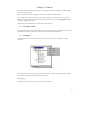
2.1
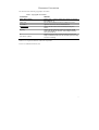
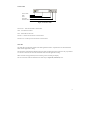
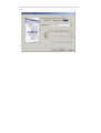
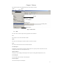
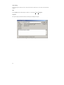
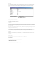
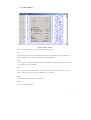
User Interface
The FDT Graphical User Interface is a Windows application that presents a work environment, which allows
the user to program FLASH memory.
Menu Bar
Tool Bar
Workspace
window
Editor
window
Output
window
Status Bar
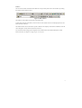
Figure 2-1 FDT Graphical User Interface
3
Menu bar
Commands are grouped into related areas on the Menu bar as indicated by the menu titles. Using the mouse the
user can select a command operation, invoke a dialog box or a window to interact with the system. Clicking the
left mouse button on a menu title will pull down that menu, from which a selection can be made.
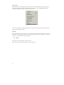
If a menu item does not perform an action directly, but instead displays a dialog box or window for further user
interaction, then its name is appended with an ellipsis (three dots, …).
Figure 2-2 Menu Ellipsis
If a menu item can also be invoked by pressing a hot key (a combination of keys), then the hot key is displayed
to the right of the item.
If a menu item toggles a feature ON or OFF then a check mark (") will be displayed next to its text when it is
ON:
Figure 2-3 Checked Menu Items
If a menu item has the symbol (8) next to it then a cascading or hierarchical menu is available. Clicking on the
menu item will reveal the cascading menu:
Figure 2-4 Cascading Menus
Menus can also be selected directly from the keyboard by pressing the ALT key followed by the corresponding
key of the underlined letter or number for the menu item that the user wants to select, e.g. press ALT+F, O in
sequence to open a project ([File->Open]).
4
Toolbars
FDT has several toolbars located below the Menu bar. This provides quick access to FDT features by clicking
the respective button with the mouse.
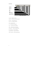
Figure 2-5 FDT Toolbars
The buttons on each toolbar are arranged in associated groups.
To find out the function of the button, move the mouse over the button and a hint will be displayed next to the
button and in the status bar.
The toolbar buttons can be customized to provide a button for the majority of the features available in FDT and
can be arranged in an order that the user finds convenient.
For more details about changing the arrangement of the toolbar buttons and a detailed description of each
button’s function, see chapter 4, Configuring the User Interface.
5
Edit toolbar
New File
Open File
Save File
Save All
Print
Cut
Copy
Paste
Match Braces
Insert Template
Toggle Bookmark
Open an S-Record
Figure 2-6 Edit Toolbar
New File - launches a new file.
Open File - launches the ‘Open’ dialog box.
Save File – saves the active file.
Save All – saves all the open files.
Print – prints active file.
Cut – cuts data to the clipboard.
Copy – copies data to the clipboard.
Paste – pastes data from the clipboard.
Match Braces – finds the matching brace.
Insert Template – inserts a template.
Toggle Bookmark – toggles a bookmark.
Open an S-Record – opens an S-Record file.
6
FDT toolbar
Connect
Disconnect
Erase Blocks
Blank Check
Upload
Download Active File
Checksum
Go from Address
Cancel
Configure Flash Project
Figure 2-7 FDT Toolbar
Connect - connects the device to the interface.
Disconnect - disconnects the device from the interface.
Erase Blocks - launches the ‘Erase Block’ dialog box to erase all or individual blocks of the device FLASH
memory.
Blank Check - checks whether or not the FLASH section of the target device is blank.
Upload - launches the ‘Upload Image’ dialog box to allow data to be obtained from the target device.
Download Active File - downloads the current device image.
Checksum – returns a sum of the data in the FLASH.
Go from Address – launches a dialog to select the address to execute from.
Cancel – Cancels the current FLASH operation.
Configure Flash Project - launches the ‘Configure Flash Project’ dialog box.
7
S Record toolbar
View as Bytes
View as Words
View as DWords
Align view to 8 bytes
Toggle ASCII
Find
Find and Replace
Create Selection
Fill Selection
Properties
Figure 2-8 S Record Toolbar
View as Bytes - view the file data as 8 bit bytes.
View as Words - view the file data as 16 bit words.
View as DWords - view the file data as 32 bit double words.
Align view to 8 bytes - data is displayed on each line as 8 bytes. The number of bytes that can be
accommodated on each line is dependent upon the size of the window.
Toggle ASCII - turns ASCII data ON or OFF
Find - launches the ‘Find’ dialog box.
Find and Replace - launches the ‘Replace’ dialog box.
Create Selection - selects a block of the specified size in the active file.
Fill selection - launches the ‘Fill’ dialog box.
Properties – launches a dialog with information about the active S Record.
8
Search toolbar
Find in Files
Data
Find
Find Next
Find Previous
Figure 2-9 Search Toolbar
Find in Files – finds selected data in selected files.
Data – is used for the searches.
Find – locates data in active file.
Find Next – locates next occurrence of search criteria.
Find Previous - locates previous occurrence of search criteria.
Status Bar
The Status Bar is located at the bottom of the FDT application window. It provides the user with information
about what the application is doing.
The left section of the Status Bar describes the action of the Toolbar items as the mouse arrow key is positioned
over an item or describes the user with information about what the application is doing.
When an action is being performed, the next section gives an increasing bar display.
The rest of sections of the bar indicate the state of the keys of Caps Lock, Num Lock, or etc.
9
Pop-up menus
Many windows have local pop-up menus in order to make commonly used features easier to access. These
menus are invoked by clicking the right mouse button in the window (or pressing SHIFT+F10) and then
selecting the required menu option. An example pop-up menu is:
Figure 2-10 Pop-up Menu
The contents and operation of specific pop-up menus are explained in detail in the description of each FDT
window, see the chapter 6, Windows.
Data entry
When entering data in the ‘Find’, ‘Replace’ or ‘Fill’ dialog boxes only hexadecimal or ASCII values can be
used, based on the ASCII Search check box. When entering hexadecimal values a preceding ‘0x’ is fixed in the
entry text box, so hexadecimal values are appended.
2.2
Help
FDT provides on-line information for using the system.
Help can be invoked by pressing the F1 key or via the ‘Help’ menu.
10
2.3
Hot Keys
There are various hot keys for frequently used operations. These are as follows by category:Description
Hot Key
Help
Help
F1
Context Sensitive Help
Shift+F1
File Commands
Open File
Ctrl+O
New File
Ctrl+N
Close File
Ctrl+F4
Open S-Record
Ctrl+R
Save All
Shift+Ctrl+ S
Save
Ctrl+S
Print
Ctrl+P
Edit Commands
Undo
Ctrl+Z
Redo
Ctrl+Y
Cut
Ctrl+X
Copy
Ctrl+C
Paste
Ctrl+V
Clear
Del
Select All
Ctrl+A
Find
Ctrl+F
Find In Files
F4
Replace
Ctrl+H
Goto Line
Ctrl+G
Match Braces
Shift+Ctrl+ M
Workspace
Alt+K
Output
Alt+U
View
Window
View as ASCII
Alt+A
View as Bytes
Alt+1
View as Word
Alt+2
View as Dword
Alt+4
Align to 8 Bytes
Alt+8
11
Chapter 3 Basic Operation
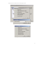
3.1
Starting FDT
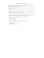
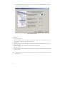
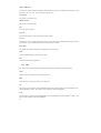
To start FDT, open the ‘Start’ menu of Windows and select ‘Renesas’ from ‘Program’, ‘FLASH Development
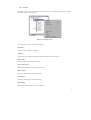
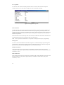
Toolkit 3.0’, and the FDT shortcut. The ‘Welcome!’ dialog box will open by default.
To create a new workspace, select ‘Create a new project workspace’ and click the ‘OK’ button. To open a
recent workspace, select ‘Open a recent project workspace’ and click the ‘OK’ button. To open an existing
workspace, select ‘Browse to another project workspace’ and click the ‘OK’ button.
Figure 3-1 Welcome! Dialog
12
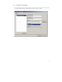
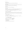
3.2
Creating a New Workspace
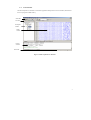
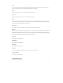
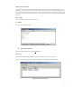
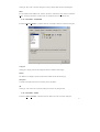
(1) Enter the workspace name(Project name is same as a default), then click the ‘OK’ button. (If you wish
to change or create a directory, input a directory name or use ‘Browse...’ button)
Figure 3-2 New Workspace
13
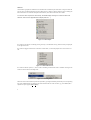
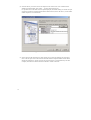
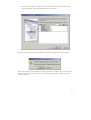
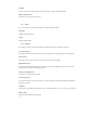
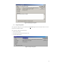
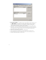
(2) Select the device you wish to use from the drop-down list. If there exists a user-created kernel in
addition to the default path, select ‘Other…’ to specify the kernel file (.fcf).
It is possible to have more than one kernel option displayed, and double clicking on a kernel will open
an optional “readme.txt” file that has information about the kernel (such as the device, version number
and the compilers it was created with).
Figure 3-3 Device and Kernel Selection
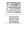
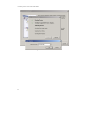
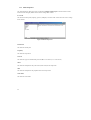
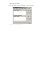
(3) Select a port from the drop-down lists, then click the ‘Next’ button. In addition to the serial ports,
there is also an option to use USB. Note that the USB Flash Development Module interface board
(FDM) will appear above ‘COM1’ in the list of ports. If the target is connected directly to the host
computer, the connection interface should be selected to ‘Direct Connection’.
14
Figure 3-4 Communications Port
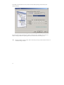
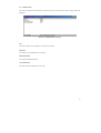
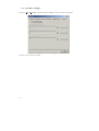
If the 0.18um Generic Wizard is being used, then to communicate with the device, if the FDM is also used, the
following screen will be shown.
Figure 3-5 FDM Generic 0.18um Setup
Note
Setting the FDM pins requires caution. Please confirm the pin settings with the hardware manual even
if a default setting is available.
15
If the FDM is selected, then the user may be able to select the FDM pin settings as determined by the
subsequent dialogs.
Figure 3-6 FDM Pin Settings
The previous dialog shows the settings for a number of FDM pins. This is for BOOT mode. If there are a
number of settings available the ‘Operating Mode’ list box can determine which setting to use.
Note
16
Setting the FDM pins requires caution. Please confirm the pin settings with the hardware manual even
if a default setting is available.
The following dialog shows a similar dialog, this time to set the pins after a reset signal has been sent to the
device.
Figure 3-7 RESET Pin Settings
17
(4) Enter the numerical values for the input clock, select the main or peripheral multiplier from the dropdown list, and click the ‘Next’ button.
Figure 3-8 Device Settings
Supplementary:
1. CPU Crystal Frequency
Enter the frequency of the CPU clock or the crystal generator as integers or in a format such as xx.xx. You
can only input two digits to the right of the decimal point.
2. Clock Mode
A clock mode needs to be selected depending on the target device. Select a value from the drop-down list.
3. Multiplier for CKM
Select the multiplier of the system clock (master clock) for the input clock.
4. Multiplier for CKP
The frequency rate (CKP) selected depends on the target device. Enter the multiplier of the peripheral clock
for the input clock.
Note
18
To enter the clock mode, input clock, and frequency rate, refer to the hardware manual and confirm the
range to be set.
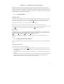
(5) Select the operating mode and baud rate from the drop-down lists, then click the ‘Next’ button.
Note
For the serial port baud rate, refer to the hardware manual and select a rate where the variance is within
3% for the clock frequency used.
Figure 3-9 Connection Type
Supplementary:
1. Use Default Baud Rate
When this check mark is removed, other than the default value can be selected from the drop-down list.
19
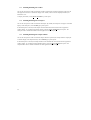
(6) Select the protection level for programming the FLASH ROM and the messaging level, then click the
‘Finish’ button.
Figure 3-10 Programming Options
20
(7) If a Generic 0.18um device is selected, then a series of screens appear. Once selected, there is little
information available, since FDT will establish the correct information.
Figure 3-11 Generic Boot Device Selection
Pressing the ‘Next’ button will result in confirmation being required that the process should be continued.
Figure 3-12 Generic Boot Confirmation
After this, FDT displays a dialog that displays the progress, and pauses on the device. Since some devices have
a number of similar devices associated with it, a list is provided of compatible devices that the user needs to
select the correct device.
21
A similar process occurs with Clock Modes.
Figure 3-13 Generic Boot - Device
22
Having selected the Clock Mode, the Generic wizard completes as below.
Figure 3-14 Clock Mode
Figure 3-15 Generic 0.18 setup complete
23
3.3
Saving a Workspace
When the [File->Save Workspace] menu option is selected, the FDT workspace can be saved.
3.4
Closing a Workspace
Select [File->Close Workspace] to close the FDT workspace. If the workspace or its project has changed, a
dialog box asks if the user wishes to save the project. Select ‘Yes’ if the workspace is to be saved, ‘No’ if the
workspace is not to be saved, and ‘Cancel’ to return to the workspace.
3.5
Exiting FDT
To exit FDT, select [File->Exit], press the Alt + F4 key, or select the ‘Close’ option from the system menu (the
system menu can be opened by clicking the icon in the upper-left are of the title bar).
3.6
(1)
Programming the Data to the FLASH ROM
When the target file (S-Record file) is downloaded:
1. Select [Project->Add Files…] or press the INS key to add the file to be downloaded to the project.
2. Click the right mouse button on the file (*.mot) displayed in the workspace window, and select ‘Download
File’.
3. Programming will be completed when ‘Image successfully written to device’ is displayed in the output
window.
(2)
When the device image is downloaded:
1. Add the target file to the project. (Same as item 1 of (1) above.)
2. Click the right mouse button on the file (*.fpr) displayed in the workspace window, and select ‘Download
Image’.
3. Programming is complete when ‘Image successfully written to device’ is displayed in the output window.
24
3.7
1.
2.
3.
4.
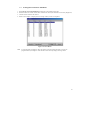
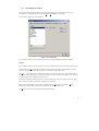
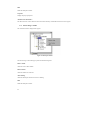
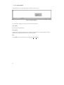
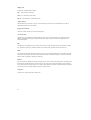
Erasing Data from the FLASH ROM
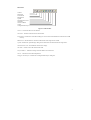
Select [Device->Erase FLASH blocks] to display the ‘Erase Blocks’ dialog box.
Select the block to be erased. (When Name of the block is clicked, the block name is inversely displayed.)*
Click the ‘Erase’ button to start erasure.
When ‘Erase complete’ is displayed in the message window, erasure is completed.
Figure 3-16 Erase Blocks
Note
To erase all blocks, clicking the ‘Select All’ button inversely displays all blocks. To erase the
programmed block, clicking the ‘Select Written’ button inversely displays the target block.
25
3.8
1.
2.
3.
4.
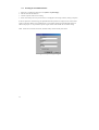
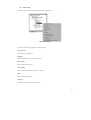
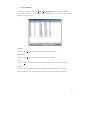
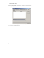
Reading the FLASH ROM Data
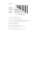
Display the ‘Upload Image’ dialog box from [Device->Upload Image].
Enter the start and end addresses.
Click the ‘Upload’ button to start reading.
When ‘Successfully read xxx bytes from device’ is displayed in the message window, reading is complete.
If the user specifies an Absolute image, the uploaded data will be placed in an image the size of the FLASH
memory at the same address it was uploaded from. Use an Absolute Image if the uploaded data needs to be
added to the project. It is not possible to upload a region outside of the FLASH into an Absolute Image.
Note
When FDT is started in boot mode, the flash memory data has already been erased.
Figure 3-17 Upload Image Dialog
26
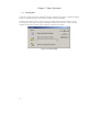
Chapter 4 Configuring the User Interface
When the user interface for FDT was designed an attempt was made to make frequently used operations
quickly accessible and have related operations grouped in a logical order. However, when the user is in the
middle of a long session he may find it more useful to have a different arrangement of the user interface items.
FDT facilitates this user customization. This chapter describes how the user interface can be arranged and how
various aspects of the display can be customized.
4.1
Arranging Windows
Minimizing windows
When an operation is finished on an open Editor window but it may be necessary to look at it in its current
state later, it can be reduced to an icon, this is called minimizing the window. To minimize a window either
click on the ‘minimize’ button of the window, or select [Minimize] from the window drop-down menu.
The window is minimized to an icon at the bottom of the Editor window.
Note
The icon may not be visible if there is another window open over the bottom of the screen.
To restore the icon back to a window either double click on the icon, or click once to pop up the icon menu and
select [Restore], or select required window from the Menu bar [Window] drop-down menu.
Tiling windows
After some time there may be many windows open on the screen. All the windows can be arranged in a tile
format with none of them overlapping each other using the "Tile Windows" option. To invoke this select the
[Window->Tile Horizontally] or [Window->Tile Vertically] menu option.
All currently open windows are arranged in a tile format. Windows that are minimized to icons are not
affected.
4.2
Locating Currently Open Windows
When many windows are open in the FDT application window it is quite easy to lose one of them behind the
others.
Locating a specific window
There are two methods to find the lost window.
1. To select a specific window, invoke the [Window] menu. Click on the required window from the list of
open windows at the bottom of the menu. The currently selected window will have a check mark next to it
in the window list.
The window selected will be brought to the front of the display. If it is minimized the icon is restored to a
window.
2. A specific window can also be selected by clicking on the tab containing the file name at the bottom of the
Editor window. If the window is not minimized it will be brought to the front of the display. If it is
minimized, the minimized icon will be brought to the front of the display.
27
4.3
Enabling/disabling the Toolbar
The user has the option to enable or disable the Toolbar. By default, the Toolbar is displayed at the top of the
FDT application window. To disable the display of the Toolbar, select each of the displayed toolbars, and
disable their view.
To display the toolbar, use the [Tools->Customize…] menu option.
4.4
Enabling/disabling the Workspace
The user has the option to enable or disable the Workspace. By default, the Workspace is displayed. To disable
display of the Workspace, select the Hide pop-up menu option.
If the disable option is selected, the Workspace will be disabled and removed from the FDT application
window display. To re-enable the Workspace display, select the [View->Workspace] menu option. The
Workspace will be enabled and added to the FDT application window display.
4.5
Enabling/disabling the Output Window
The user has the option to enable or disable the Output Window. By default, the Output Window is displayed.
To disable display of the Output Window, select the Hide pop-up menu option.
If the disable option is selected, the Output Window will be disabled and removed from the FDT application
window display. To re-enable the Output Window display, select the [View->Output] menu option. The
Output Window will be enabled and added to the FDT application window display.
28
4.6
Customizing the Toolbar
The selection and arrangement of buttons displayed on the Toolbar can be customized to suit a user’s
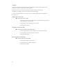
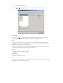
requirements. To change the display invokes the [Tools->Customize…] menu option.
The ‘Customize’ dialog box will be displayed:
Figure 4-1 Customize FDT
The ‘Customize’ dialog box has a number of tabs, which are further described in Chapter 6 Windows.
Toolbars
The ‘Toolbars’ tab allows the user to select a group (e.g. workspace) and to select the functions for that group.
A check mark in the ‘Show Tooltips’ box indicates that the action of the button will be displayed when the
mouse arrow is pointing to the button. If the box is unchecked no action is displayed.
The ‘New…’ button launches the ‘Toolbar Name’ dialog box which allows the user to name and generate a
new toolbar. After entering the new name and clicking on ‘OK’, the new name will be added to the ‘Toolbars’
list and an empty toolbar is displayed on the interface.
Selecting the Commands tab allows the user to select and add buttons to the new toolbar. The user can place
the new toolbar anywhere on the GUI by dragging it with the mouse.
When a user created toolbar is selected in the ‘Toolbars’ list, the ‘Reset’ button is renamed to ‘Delete’.
Clicking on this button will remove the new toolbar from the list and from the GUI.
The ‘Reset’ button resets the selected toolbar to its default settings.
29
Commands
This tab shows the buttons and describes the action for each button in each group and allows the user to
customize the toolbar according to an individual application.
Clicking on an item in the ‘Categories’ box displays the buttons available for that category.
The ‘Buttons’ area displays a picture for each button in the selected category.
To obtain a description of the action of a button, click on that button. The description will appear in the
‘Description’ area.
Adding a button to the Toolbar
! To add a button to the Toolbar:
1. Select the button from the appropriate category, by pointing the mouse pointer at the
button and press the left mouse button.
2. Drag the button to the required position in the Toolbar.
3. Release the mouse button.
Positioning a button in the Toolbar
! To move a button position in the Toolbar order:
1. Select the appropriate button on the Toolbar to move with the mouse as above.
2. Drag the button to the required position on the toolbar.
3. Release the mouse button.
Removing a button from the Toolbar
! To remove a button from the Toolbar:
1. Select the button with the mouse as above.
2. Drag the button to the ‘Customize’ dialog box.
3. Release the mouse button.
30
Chapter 5 Menus
This document follows the standard Microsoft menu naming convention:
Menu
Bar
Menu
Title
Hot Key
Drop-down
Menu
Ellipsis
Cascading Menu
Menu Option
Figure 5-1 FDT Menus
5.1
File
The ‘File’ menu is used for aspects of the program that access data files.
New
This creates a new text file in the editor window.
Open…
This opens a file for display in the editor window. It assumes a text file.
Close
This will close the current active file in the editor window.
New Workspace…
Launches the ‘New Workspace’ dialog box allowing the user to specify the name and location of a new
workspace and creates a new workspace directory.
Open Workspace…
Launches the ‘Open’ dialog box allowing the user to open an existing FDT Workspace file (.aws).
Save Workspace
Saves the details of the currently active Workspace.
Close Workspace
Closes the currently active Workspace.
31
Open an S-Record…
Launches the ‘Open an S-Record’ dialog box allowing the user to open an existing file. The file may be an SRecord file (.rec, .mot, .a20, .a37) or a Device Image file (.fpr).
Save Session
This feature is not used in FDT.
Refresh Session
This feature is not used in FDT.
Save
Saves the current active file.
Save All
Saves all files that have not been saved on the Editor window.
Save As…
Launches the ‘Save As’ dialog box allowing the user to save and name the uploaded Device Image file with a
.fpr extension, or if an S-Record file is active to rename and save that file.
Page Setup…
This displays the options available for configuring the page for printing.
Print…
Uses the standard dialog for printing the active file.
Exit
Closes and exits the FDT application.
5.2
Edit
The ‘Edit’ menu is used for aspects of the program that access or alter data in the Editor window.
Undo
Allows the user to reverse the previous editing operation.
Redo
Allows the user to reverse the previous Undo operation.
Cut
This will remove the contents of the highlighted block from the window and place it on the clipboard in the
standard Windows manner. This option is only available if a block is highlighted.
Copy
This will copy the contents of the highlighted block to the clipboard in the standard Windows manner. This
option is only available if a block is highlighted.
32
Paste
This will copy the contents of the Windows clipboard into the child window at the current cursor position.
Note
If more than one byte is selected, the Paste option is not available.
Clear
Deletes selected characters. In an S-Record file, this has no function.
Select All
Selects all the information in the active file in the editor window.
Find…
This will launch the ‘Find’ dialog box allowing the user to enter either hexadecimal or ASCII data. The scope
of the search is bounded by the area selected, for the active file in the Editor window. If a match is found, the
Editor window is updated to display the found data.
Find In Files…
This launches a dialog to allow data to be located in files external to the active file.
Replace…
This will launch the ‘Replace’ dialog box allowing the user to enter either the hexadecimal or ASCII data to be
found and the replacement data, in the same format. The scope of the search is bounded by the area selected,
for the active file in the Editor window. If a match is found, the Editor window is updated to display the found
data, click on the now enabled ‘Replace’ button to replace the data.
Goto Line
This feature is not used in FDT.
Match Braces
This feature is not used in FDT.
Bookmarks
This feature is not used in FDT.
Templates
This allows standard text to be added an active text files in the editor window.
Toggle Breakpoint
This feature is not used in FDT.
Enable/Disable Breakpoint
This feature is not used in FDT.
33
Columns
This has no effect with S Records, but with text files allows a gutter on the left hand side.
Define Column Format…
This feature is not currently used in FDT.
5.3
View
The ‘View’ menu is used to display Workspace window and Output winodw.
Workspace
Display Workspace window.
Output
Display Output window.
5.4
Project
The ‘Project’ menu provides high-level control and facilities for projects within the workspace.
Set Current Project
This option allows the user to select the active project where there are multiple projects in the workspace.
Insert Project…
This option allows the user to create a new project, and add it to the workspace.
Dependent Projects…
This creates relationships between projects so that if one project is modified and a file is used in another
project, there is a association between the projects.
Edit Project Configuration…
This option is currently not used in FDT.
Create Project Type…
If a project were likely to be reused, creating it as a type of project would reduce the amount of duplicated
information required.
Add Files…
Launches the ‘Open’ dialog box allowing the user to add S-Record files (.rec, .mot, .a20, .a37) to the project.
Remove Files…
Removes the selected file from the project.
34
File Extensions…
This option allows the user to select which file extensions are recognized by FDT.
Components…
This option shows any additional components used in FDT (currently not used).
Download Image
Loads the open Device Image file into the target FLASH memory.
Rebuild Image
Rebuilds the target files into a Device image file (Binary Image) for subsequent downloading to the target
FLASH memory.
5.5
Tools
The ‘Tools’ menu is used to launch additional FDT features, which are not related to either projects or target
devices.
Administration…
This displays a dialog with the tools available to the user under different categories.
Simple Interface…
Writes the created project to the flash memory by using one button.
Customize…
This allows the user to customize FDT, and is covered in more detail in section 6.13.
Options…
Allows access to additional features, some of which are reserved for future enhancements.
Format Views…
This allows the user to change the appearance of different windows.
Launch External Debugger…
This option is reserved for later enhancements.
Launch Slave FDT…
Allows the user to launch a new copy of FDT.
35
5.6
Window
The ‘Window’ menu is used to alter the display of currently open windows within the FDT GUI. Files
displayed in the Editor window are appended to the following list, these files are identified by their filename
and the currently active file is denoted by check mark.
Cascade
This option allows multiple windows to be staggered so that each file is visible.
Tile Horizontally
This option allows the windows to be displayed with maximum possible horizontal width.
Tile Vertically
This option allows the windows to be displayed with maximum possible vertical height.
Arrange Icons
This option arranges the file icons in rows at the bottom of the screen.
Close All
This option closes any files open in the editor window.
‘file name’
This option becomes active when a file name is selected and checked.
5.7
Device
The ‘Device’ menu provides control facilities for interacting with the target device.
Connect to Device
This connects the GUI to the device if it is not connected. Messages will appear in the Output window if the
connection cannot be made.
Disconnect
This disconnects the GUI from the device if it is connected. Messages will appear in the Message log if the
connection cannot be made.
Erase FLASH Blocks
This launches the ‘Erase Blocks’ dialog box.
The ‘Erase Blocks’ dialog box allows the user to specify which blocks are to be erased. The Written column
indicates whether data is present in the block.
To start the operation, select the required block names in the list and then click the ‘Erase’ button.
36
Blank Check
This launches a blank check on the device FLASH and reports back to the Output window.
Upload Image
This launches the ‘Upload Image’ dialog box, which enables the uploading of a range of data from the target
device. This is intended for access with FLASH memory. The data is placed in the Editor window.
Download Active File
This downloads the current active file into the target FLASH memory.
FLASH Checksum
This launches a checksum calculation on the device FLASH and reports back to the Output window.
Go From Address…
This launches a dialog that allows the user to select an address to execute code from. There is an option to
select an indirect address mode, so that the address referenced is itself an address of where the code needs to
run from.
User Boot Area
This menu is enabled for 0.18µm devices. When User Boot Area is selected (enabled), FDT specifies to write
the data to the this area of flash ROM, to upload image and to blank check in the user boot area of the 0.18µm
device before programming. The User Boot Area may be used to provide user defined boot sequences different
from the factory sequence.
Cancel Operation
Cancels the current FLASH operations of Download, Upload, Erase or a connection attempt, if they are active.
5.8
Help
The ‘Help’ menu is used to access additional information on how to use the functionality provided by FDT.
Help Topics
Launches the Help system for FDT. The ‘Help Topics’ dialog box for FDT is displayed, enabling help to be
accessed on required FDT subjects through several methods.
Technical Support
This allows the user to report a problem with FDT.
About FDT…
Launches the ‘About FDT’ dialog box, through which additional information regarding FDT can be accessed:
• FDT version.
• Copyright information.
37
38
Chapter 6 Windows
This chapter describes each child window type, the features each supports and the options available through
their associated pop-up menus.
There are three main windows - Workspace window, Editor window and Output window.
Most windows have local pop-up menus in order to make commonly used features easier to access. These
menus are invoked by clicking the right mouse button within the window (or pressing SHIFT+F10) and then
selecting the required menu option.
Windows may also be launched from a number of the main menu items.
6.1
Workspace window
The Workspace window contains details of the items in the workspace including the workspace name, projects
contained in the workspace and for each project their Device Image files and Target files.
6.2
Workspace
The Workspace is the first item in the window, in the following example this is “Workspace ‘Industrial
Controller’”:
Figure 6-1 Workspace Window
Invoking certain menu items from a pop-up menu in the Workspace window will launch additional windows.
The Workspace window pop-up menu has the following items:
Insert Project…
Invoking this option allows the user to add a project to the Workspace.
39
Allow Docking
Invoking this option allows the user to select if the window is docked, or if it can “float” around the main
window.
Hide
Invoking Hide conceals the Workspace window. It is restored by [View->Workspace].
Properties
This option displays information about the Workspace including the file path.
Figure 6-2 Workspace Properties
40
6.3
Project
The Project is the next item in the hierarchy below the Workspace. In the following example, both “Display”
and “Motor Control” are Project names.
Figure 6-3 Workspace Project
The pop-up menu for Project has the following items:
Add Folder…
Allows an additional folder to be included.
Add Files …
Launches the ‘Open’ dialog box allowing the user to add S-Record files to the project.
Remove Files…
Launches a dialog to select the files to remove.
Set as current Project
Sets the highlighted project as the current active project.
Remove Project
Remove the selected project from the Workspace.
Unload Project
Unloads the selected project from the Workspace.
Allow Docking
Allows the Workspace window to dock or be floating.
41
Hide
Hides the Workspace window.
Properties
Displays the project properties.
Add Files From Kernel Dir…
This allows the user to select files from the current kernel directory and add those files to the current project.
6.4
Device Image - Folder
This contains the Device Image file the project.
Figure 6-4 Workspace Folder
The Device Image - Sub Folder pop-up menu has the following items:
Remove Folder
Allows the user to delete folders.
Rename Folder
Allows the folder to be renamed.
Allow Docking
Allows the Workspace window to dock or be floating.
Hide
Hides the Workspace window.
42
6.5
Device File
The Device File is the item containing the data to Flash into the device.
Figure 6-5 Device File
The pop-up menu for Device File has the following items:
Open ‘filename’
This feature is not used in FDT.
Add Files…
Allows additional files to be added to the project.
Remove Files…
Removes files from the project.
Allow Docking
Allows the Workspace window to dock or be floating.
Hide
Hides the Workspace window.
Properties
Launches the device file properties dialog box.
43
Display Block usage…
Launches the ‘S-Record Properties’ dialog box and displays the Block usage tab.
Exclude ‘filename’
If a file is excluded, it will not be used to form the built image if Rebuild Image is selected. Once selected as
excluded, using the right mouse click, it is possible to “Include ‘filename’”.
Download File
Downloads the active file to the device FLASH memory.
File Checksum
The file checksum returns the checksum for the file using the algorithm in the kernel (EPROM style) and as a
basic checksum. The result is shown in the output window. An example is shown below:-
File Checksum: 0x07F5A651 (EPROM style), Raw Checksum:
(over address range 0x00000000 - 0x0007FFFF)
0x07F5A651
Compare File->Device Checksum
This command allows the user to swiftly check the contents of the device memory with the file. The output
window will show the sum check for both the file and the device. The user may then confirm that they are the
same.
An example is shown below:-
Calculating device checksum
Flash Checksum: 0x07F5A651 (User Area)
File Checksum: 0x07F5A651 (EPROM style), Raw Checksum:
(over address range 0x00000000 - 0x0007FFFF)
6.6
Workspace Properties
Invoked from the Workspace pop-up menu item Properties.
The ‘Workspace Properties’ dialog box shows details of:
• the Workspace Name
• its filename and path
• the time and date when the workspace was last saved
44
0x07F5A651
Figure 6-6 Workspace Properties
6.7
Project Properties
The ‘Properties’ dialog box can be invoked from the Properties right click action when the mouse is over the
project in the workspace window.
The ‘Properties’ dialog box shows details of:
• the name of the project
• the location and the file name of the project file
• its creation date and time
Figure 6-7 Project Properties
45
6.8
Flash Properties
The ‘Flash Properties’ dialog box can be invoked from Configure Flash Project in the FDT toolbar. For the
items that can be changed, double-click on them to change those contents.
#
Kernel
This shows the kernel path, frequency, protocol, multiplier, and clock mode. It also allows the user to change
those contents.
Figure 6-8 Kernel Properties
Kernel Path
This shows the kernel path.
Frequency
This shows the input clock.
Protocol
This shows the type of communication protocols (B: 0.35-µm device, C: 0.18-µm device).
CKM
This shows the multiplier of the system clock (master clock) for the input clock.
CKP
This shows the multiplier of the peripheral clock for the input clock.
Clock Mode
This shows the clock mode.
46
#
Communications
This shows the default and current baud rates and the current port. It also allows the user to change the Port and
Baud Rate.
Figure 6-9 Communications Properties
Port
This shows COM ports or USB port for connection to the device.
Baud Rate
This shows the Target Baud Rate for connection.
Default Baud Rate
This shows the default Baud Rate.
Use Default Baud
This shows whether default baud is used or not.
47
#
Device
This shows the device information. It also allows the user to select ‘BOOT Mode’ or ‘USER Program Mode’
and the ‘Direct Connection’ interface. In addition, it can specify whether or not the kernel is in the target
device.
Figure 6-10 Device Properties
Device, RAM Size, and FLASH Size
These show the information on the device.
Connection
Boot mode connection type specifies that the on-board programming BOOT mode sequence is to be initiated if
a kernel cannot be found running on the target device. This will cause the entire FLASH memory to be erased
and a kernel loaded.
If a kernel is already resident the FLASH is not erased, rather information regarding the block usage is obtained
to help prevent accidental overwriting.
User program mode connection type specifies that the on-board programming USER Program mode sequence
is to be initiated by a previously loaded user program that is used to reprogram the FLASH memory.
Interface
If the target is connected directly to the host computer, the connection interface should be selected to ‘Direct
Connection’.
Kernel resident
This shows whether a main kernel to be already resident on the target device.
User Boot Area
This shows whether the user boot area is selected or not.
Available RAM and Free RAM
These are not used in communication protocol B or C.
48
Buffer Size
This shows a size of programming the flash memory.
Device ID
This is not used in communication protocol B or C.
49
#
Programmer
This shows the state of the Function Map and allows the user to select the Device Protection Option of
Automatic, Interactive, or None and the message level option of Advanced or Standard.
Figure 6-11 Programmer Properties
Device Protection
This allows the user to select either automatic protection (Automatic) or interactive protection (Interactive) to
protect the FLASH device from accidental over-erasure and over-programming. Automatic protection will
erase blocks from the device prior to programming, as necessary. Interactive protection will ask the user before
an erase occurs. FDT can be forced to write to a block containing data. In addition, None can be selected to
disable device protection.
Whilst connected to a device FDT keeps track of the state of the FLASH blocks and is able to determine when
a programming operation will over-program a region of FLASH memory.
Note
If device protection is disabled the user is responsible for erasing the device prior to programming.
Message Level
The user can select either Standard or Advanced message levels. A standard message level generates general
FDT/target device status messages regarding high-level communications details. An Advanced message level
generates more detailed information regarding lower level communications details.
Readback Verification
After programming, FDT can verify the data was programmed successfully by performing a read-back
verification. Use this option to specify whether you would like to perform read-back verification, always, after
confirmation, or never.
Reset on Disconnect
When disconnecting from the device when used in combination with a UPB or FDM, FDT can be used to reset
the target hardware. Use this option to specify whether you would like to reset the device, always, after
confirmation, or never.
50
Reinterrogate on Disconnect
This option forces FDT to reinterrogate Generic 0.18um devices on connection. With this option set to "No"
(default), the device settings are saved in an automatically generated fcf file and re-used. With this option set to
"Yes", FDT will always reinterrogate the device for its details upon connection; this allows one project to work
with many 0.18um devices. If this option is set to "Query", FDT will ask you to select whether to reinterrogate
the device.
Function Map
This is not used in communication protocol B or C.
#
Modules
This shows each Kernel file name.
Figure 6-12 Module Properties
6.9
S-Record Properties
Invoked from the Editor pop-up menu item Properties….
Block Usage
This shows the starting, finishing address and sizes of the blocks contained in specified file.
If the file is open in the editor window, double clicking on a range highlights the selected data.
Figure 6-13 S Record Properties
51
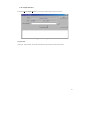
6.10 Output Window
The Output window is one of the main windows contained in the FDT GUI.
Figure 6-14 Output Window
The window has available pop-up menu that contains the following items:
Clear Window
This will clear the Output window.
Allow Docking
With this option checked the Output window is capable of being docked within the FDT application window.
With the option unchecked the Output window is a floating window.
Hide
Invoking Hide conceals the Message log. It is restored by [View->Output].
52
6.11 Editor Window
The Editor window is one of the main windows contained in the FDT GUI.
Figure 6-15 Editor Window
The window has available pop-up menu that contains the following items:
Cut
This will remove the contents of the highlighted block from the window and place it on the clipboard in the
standard Windows manner. This is only available if a block is highlighted.
Copy
This will copy the contents of the highlighted block to the clipboard in the standard Windows manner. This is
only available if a block is highlighted.
Paste
This will copy the contents of the Windows clipboard into the child window at the current cursor position.
Note
If more than one byte is selected, the Paste option is not available.
Undo
Reverses the last editing operation on the selected data.
Redo
Reverses the last undo operation.
53
Display Unit
Invokes the cascaded menu as follows:
Byte - view the data as 8-bit bytes.
Word - view the data as 16-bit words.
DWord - view the data as 32-bit double words.
Align to 8 Bytes
Data is displayed on each line as 8 bytes. The number of bytes that can be accommodated on each line is
dependent upon the size of the window.
Toggle ASCII Column
Allows the ASCII column to be removed or displayed.
Create Selection…
Launches the ‘Create Selection’ dialog box allowing the user to create a selection area by entering its start
address, end address and length. The selected area can be used in conjunction with the Clipboard, Fill or
Search and Replace.
Fill…
Launches the ‘Fill’ dialog box for the current active file to write the specified data to the selected area. When
the ‘ASCII Fill’ check box is selected, the data to be written can be specified with ASCII characters.
Find…
This will launch the ‘Find’ dialog box allowing the user to enter either hexadecimal or ASCII data. The scope
of the search is bounded by the area selected, for the active file in the Editor window. If a match is found, the
Editor window is updated to display the found data.
Replace…
This will launch the ‘Replace’ dialog box allowing the user to enter either the hexadecimal or ASCII data to be
found and the replacement data, in the same format. The scope of the search is bounded by the area selected,
for the active file in the Editor window. If a match is found, the Editor window is updated to display the found
data, click on the now enabled ‘Replace’ button to replace the data.
Properties…
Launches the ‘S-Record Properties’ dialog box.
54
6.12 Erase Blocks
‘Erase Blocks’ dialog box is invoked by [Device->Erase FLASH blocks] or the Toolbar Erase Blocks.
The ‘Erase Blocks’ dialog box allows the user to specify which blocks to erase. The Written column indicates
whether data exists in the block.
Figure 6-16 Erase Blocks
Select All
Clicking on ‘Select All’ will select all the blocks of the device FLASH memory.
Select Written
Clicking on ‘Select Written’ will select only those blocks that are not empty.
Erase
Clicking on ‘Erase’ will erase the data in the selected blocks and removes the ‘Erase Block’ dialog box.
Cancel
Clicking on ‘Cancel’ removes the ‘Erase Blocks’ dialog box without performing an erase operation.
Note
Whilst blocks that contain no data need not be erased, FDT will erase all the specified blocks.
55
6.13 Customize - Toolbars
Invoked by [Tools->Customize…] and then select the Toolbars tab in the ‘Customize’ dialog box.
Figure 6-17 Customize Toolbars Dialog
Show Tooltips
A check mark in the ‘Show Tooltips’ box indicates that the action of the button will be displayed when the
mouse arrow is pointing to the button. If the box is unchecked, no action is displayed.
New…
The ‘New…’ button launches the ‘Toolbar Name’ dialog box which allows the user to name and generate a
new toolbar. After entering the new name and clicking on ‘OK’, the new name will be added to the ‘Toolbars’
list and an empty toolbar is displayed on the interface.
Selecting the ‘Commands’ tab allows the user to select and add buttons to the new toolbar. The user can place
the new toolbar anywhere on the GUI by dragging it with the mouse.
Reset
The ‘Reset’ button resets the toolbar to the default.
Toolbar name
Reflects the toolbar selected in the list.
OK
Clicking on ‘OK’, in the ‘Toolbar Name’ dialog box adds the new name to the ‘Toolbars’ list on the ‘Toolbars’
window and invokes a blank toolbar on the GUI.
56
Clicking on ‘OK’ in the ‘Customize’ dialog box saves any changes made and closes the dialog box.
Delete
If a new toolbar has been added to the ‘Toolbars’ list and it is selected, the ‘Reset’ button is renamed to
‘Delete’. Clicking on this button will remove the new toolbar from the list and from the GUI.
6.14 Customize - Commands
Invoked by [Tools->Customize…] and then select the ‘Commands’ tab in the ‘Customize’ dialog box.
Figure 6-18 Customize Commands Dialog
Categories
Clicking on a Category from the list displays the buttons available for that category.
Buttons
The ‘Buttons’ area displays a picture of each button available for the selected category.
Description
To obtain a description of the action of a button, click on that button.
OK
Clicking on ‘OK’ removes the ‘Customize’ dialog box and saves any changes made.
6.15 Customize – Menu
Invoked by [Tools->Customize…] and then select the ‘Menu’ tab in the ‘Customize’ dialog box.
57
Figure 6-19 Customize Menu Dialog
! To add a new menu option:
1. Select [Tools->Customize…]. The dialog shown above will be displayed. Select the ‘Menu’ tab. The
first thing for you to decide is whether you are adding a global application wide tool (‘Application
wide tools’), which will be available to all of your workspaces. Or whether you wish to add a
workspace wide tool (‘Workspace wide tool’), which is only valid for the current workspace. Once
you have made the choice choose the relevant section of the dialog.
2. Click the ‘Add…’ button. If you would like to add an existing system tool to the menu then select the
‘Select from existing system tools’ radio button, choose the tool from the drop-down list and then click
‘OK’. Alternatively, if you would like to add a tool of your own then follow the remaining steps.
3. Enter the name of the tool into the ‘Name’ field.
4. Enter the command, excluding arguments, into the ‘Command’ field.
5. Enter any arguments that you would like to pass to the command into the ‘Arguments’ field.
6. Enter an initial directory in which you would like the tool to run, into the ‘Initial directory’ field.
7. Click ‘OK’ to add the menu option to the ‘Tools’ menu.
58
Figure 6-20 Add Tool Dialog
New menu options are added to the bottom of the list (i.e. bottom of the tools menu) by default.
! To modify a menu option:
1. Select [Tools->Customize…]. The dialog shown below will be displayed. Select the ‘Menu’ tab.
2. Select the menu option that you would like to modify and then click the ‘Modify…’ button.
3. Make the desired changes on the ‘Modify Tool’ dialog and then click ‘OK’.
59
Figure 6-21 Modify Tool Dialog
! To remove a menu option:
1. Select [Tools->Customize…]. The dialog shown in Figure 6-19 will be displayed. Select the ‘Menu’
tab.
2. Select the menu option that you would like to remove and then click the ‘Remove’ button.
60
6.16 Customize – Placeholders
Invoked by [Tools->Customize…] and then select the ‘Placeholders’ tab in the ‘Customize’ dialog box.
Figure 6-22 Customize Placeholders Dialog
This allows the user to choose placeholders for directories.
61
6.17 Customize – Debugger
Invoked by [Tools->Customize…] and then select the ‘Debugger’ tab in the ‘Customize’ dialog box.
Figure 6-23 Customize Debugger Dialog
This option is not currently used in FDT.
62
6.18 Customize – Log
Invoked by [Tools->Customize…] and then select the ‘Log’ tab in the ‘Customize’ dialog box.
Figure 6-24 Customize Log Dialog
Currently this tab is not used in FDT.
63
6.19 Customize – Help
Invoked by [Tools->Customize…] and then select the ‘Help’ tab in the ‘Customize’ dialog box.
Figure 6-25 Customize Help Dialog
This allows the user to add additional help files.
64
6.20 Simple Interface
Invoked by [Tools->Simple Interface…]. Clicking on ‘Back’ displays the previous screen.
Figure 6-26 FDT Simple Interface
Program Flash
Clicking on ‘Program Flash’ allows FDT to download the specified file to the FLASH memory.
65
Chapter 7 Upgrading to FDT 3.0
If the project being used needs to be upgraded to FDT 3.0, it is recommended that a new workspace and project
is created using the wizard. This will ensure that the new settings are generated as required by FDT. The
workspace files used by FDT 2.2 are not compatible with FDT 3.0 due to the enhancements included in FDT
3.0.
If the project specifically requires the kernels distributed from the earlier version of FDT 2.2, it is possible to
choose the “Other” option to select the user defined kernel. It is recommended that wherever possible the latest
kernels are used.
66
Renesas FLASH Development Toolkit 3.0
(for Windowsâ 98/Me, Windows NT â 4.0, Windowsâ 2000 and
Windowsâ XP) User's Manual
Publication Date: Rev.1.00, June 16, 2003
Published by:
Sales Strategic Planning Div.
Renesas Technology Corp.
Edited by:
Technical Documentation & Information Department
Renesas Kodaira Semiconductor Co., Ltd.
2003 Renesas Technology Corp. All rights reserved. Printed in Japan.
Renesas FLASH Development Toolkit 3.0
(for Windows® 98/Me, Windows NT® 4.0,
Windows® 2000 and Windows® XP)
User’s Manual
1753, Shimonumabe, Nakahara-ku, Kawasaki-shi, Kanagawa 211-8668 Japan
REJ10B0022-100H