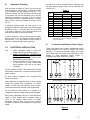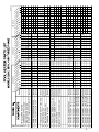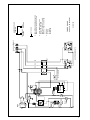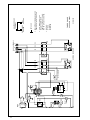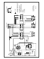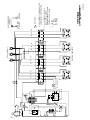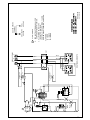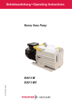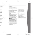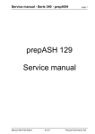
1
POOL HEATER
with built-in flow switch
EXPORT MODELS:
32212CE-E thru 32272PHS-E
33812CE-E thru 33872PHS-E
34112CE-E thru 34172PHS-E
installation, operation and maintenance
DO
UL
SW
I
co
ate
G
PO
s
MM
IN
MO
D
.N
O.
kW
MA
X.
TO DIS
C W
EIT UN ON A
HE IT B NEC RN
R EF T
TE O AL ING
SE
RM RE L P
RV
IN RE OW
AL MO E
I
CO VIN R
NO PAN CE A
VE G
R
T O EL CC
ES
BS
S
TR
UC
T
AM
WO
PS
RK
IN
G
OL
AN
D
SE
SP
AH
RIA
LN
VO
PH
O.
LT
AS
S,
PR
E
50
ES
/60
SU
CY
RE
CL
EA
kW
P.S
.C
.
EA
.I.
HY
CH
D
EL
TE
EM
ST
EN
T
EA
TE
R
P.S
.I.
EL
EM
EN
T
ON
FL
OW
OF
F
TE
MP
CO ERA
NT TU
RO RE
L
ET
TL
OU
T
LE
IN
Publication 1-2012
WARNING
Only qualified personnel, as defined by National
Electric Code Article 100, should install and
maintain this equipment. Unauthorized alteration
or improper maintenance of this unit may release
the manufacturer from any warranty claims. The
installation must be in accordance with the
instructions in this manual and applicable local
plumbing and electrical codes.
INTRODUCTION
This manual provides installation procedures,
operating and maintenance instructions and a parts list
for the Coates Pool Heater.
Your Coates Electric Swimming Pool Heater has been
designed and engineered to provide you with the most
progressive quality heating system possible.
Its
operation is efficient and pollution-free. Models are
available for every size or make of pool.
To insure a long life of trouble-free service, your
Coates Pool Heater should be carefully installed in
accordance with the instructions given in this manual.
Failure to do so may damage the pool heater and the
pool equipment to which it is connected.
Only
qualified personnel should install and maintain this
unit, and, of course, local plumbing and electrical
codes have precedence over these instructions.
1.0
DESCRIPTION
The Coates Swimming Pool Heater consists of a
heating tank with external enclosure, and the electrical
heating and control system. In order to help maintain
the heater in a satisfactory manner, a brief description
of its components and their operation is included for
the customer’s convenience.
The pressure vessel and its enclosure comprise the
main mechanical portion of the pool heater.
The pressure vessel, in conjunction with the flow
switch and heating element are the only portions of
this equipment in contact with the water.
The external enclosure is a sheet steel case totally
enclosing the pressure vessel and electrical
components. The enclosure is coated with a rust
inhibiting, powder coat finish.
The electrical system, which is the heart of this unit,
can be considered as three separate systems
engineered to provide optimum use of energy. They
are as follows:
2
(1)
The heating elements; mounted on a four-bolt
flange. There are either 2, 3 or 4 elements.
(2)
The control system; consists of the pilot switch,
high limit thermostat, flow switch, temperature control,
magnetic contactors and transformer. These controls
are wired into a 120V or 220V control circuit designed to
control the temperature of the water leaving the heater.
The high-limit thermostat is designed to open the control
circuit and cut off the power in the event of excessive
temperature.
A flow switch is built-in to prevent the pool heater from
operating without water flow.
The flow switch will
activate at flow rates of 20 GPM (1.26 L/sec) or greater.
(3)
The main current-carrying components; are
the contactors. These are wired into circuits which carry
the full amperage draw of the elements. The contactors
function during a high temperature condition to deenergize the elements.
The heater has a temperature controller adjustable from
70°F(21°C) to 104°F(40°C) and has one manual reset
type high temperature limit thermostat set at 122°F
(50°C).
2.0
LOCATION AND PLUMBING
A.
Installation: Location
Coates swimming pool heaters are quiet, do not expel
exhaust fumes, and may be conveniently located in shed
or basement. Normal positioning of the pool heater
should be in close proximity to the pool filtration system.
Select a location conveniently close to incoming
electrical service and where excessively long piping runs
are not required.
Minimum clearance:
Front
Left
Right
Top
Back
PHS/CPH
36 (914)#
18 (457)
*
18 (457)
6 (153)
CE
36 (914)#
4 (102)
4 (102)
20 (508)
*
* Required clearance is based on plumbing configuration used.
# Refer to NEC Table 110.26 (A)(1)
- Dimensions: Inches (mm)
- Temperature control is located on the front side.
B.
Installation: Plumbing
Pipe the heater as shown in Figure 2 to the inlet and
outlet openings on the right side. Connect the heater
in line between the filter discharge and pool. The
water line coming from the filter should be connected
to the heater inlet, and the discharge line to the pool
should be connected to the outlet. The pool will not
heat properly unless it is plumbed correctly. If plastic
pipe is used, it should be suitable for at least 122°F
(50 °C).
Ground wires must be insulated copper conductor and
the same size as supply wiring, but not less than #12
AWG (4 mm2).
Table 1
WIRE SIZE: AWG(mm2)
220V/3Ø
380V/3Ø
415V/3Ø
8(10)
10(6)
10(6)
8(10)
10(6)
10(6)
6(16)
8(10)
8(10)
4(25)
8(10)
8(10)
3(35)
6(16)
6(16)
2(35)
6(16)
6(16)
1(50)
4(25)
4(25)
3/0(95)
3(35)
3(35)
3/0(95)
3(35)
3(35)
3/0(95)
2(35)
3(35)
4/0(120)
1(50)
2(35)
KW
12
15
18
24
30
36
45
54
57
60
72
A plumbing bypass around the pool heater is not
necessary unless flow rates though the heater exceed
80 GPM (5 L/sec). A minimum flow rate of 20 GPM
(1.26 L/sec) is required. Lack of sufficient flow will not
allow the flow switch to activate the heater.
It may be necessary, in larger Olympic-sized or public
pools, to use two or more heaters to obtain sufficient
KW capacity. If so, the heaters must be placed in
parallel, so that each heater takes equal flow.
Suggested size for insulated copper conductor
wires. Based on 125% correction factor for wire
with 90°C insulation.
A.
3.0
ELECTRICAL INSTALLATION
First:
1. Check nameplate rating to insure the
heater matches your electrical supply.
2. CHECK ELECTRICAL CONNECTIONS
TO ALL COMPONENTS within the heater
for tightness. These can become loose
during shipment and handling.
3. Check components for any moisture, rust,
or dust which may have accumulated
during shipping, and clean or dry where
necessary.
To Connect Pool Heater to Power Supply
These pool heaters have branch supplemental fusing
already installed in the element circuitry; see wiring
diagrams. To connect to the power supply, one needs
only to protect the main supply lines, either with a circuit
breaker or fused disconnect switch (Figure 1).
Suggested wire sizes are shown in Table 1.
or
All pool heaters covered in this manual have integral
thermostats, transformers, contactors and sequencers
where required.
All other internal connections are completed and
tested at the factory.
Ground
Line 1 Line 2
Line 1 Line 2
Ground
Wiring Diagram: Single-Phase Models
Wiring diagrams on pages 6 through 14 show internal
wiring and required field connections for various
models. Consult your local electrical code for proper
wire and conduit sizes, and other local requirements.
or
Do not connect the pool heater to, or operate at, a
voltage other than the voltage rated on the nameplate.
Bring wires of adequate size from a fused disconnect
switch or circuit breaker with an ampere rating of
125% of the ampere rating shown on heater
nameplate. Refer to Table 1 for wire sizes. Connect
the power conductors to bus assembly on inside of the
heater.
ØA
ØB
ØC
ØA
ØB
ØC
Ground
Ground
Wiring Diagram: Three-Phase Models
Figure 1
3
B.
Startup Procedure:
4.0
1. Make sure that the pump is on and that there is at
least 20 GPM (1.26 L/sec) flow through the pool
heater. The heating elements will fail if allowed to
operate dry.
MAINTENANCE
Element Inspection and Replacement:
1. Turn off power at main disconnect switch and turn
off water at water supply line.
2. Drain pool heater.
3. Remove left end service access panel.
4. Disconnect element leads.
5. Remove the four (4) element flange retaining nuts
and extract element.
6. Installation is the reverse of steps 1 through 5.
(Reinstall element with new gasket)
2. Check temperature control setting, also, examine
wiring for loose connections, etc.
3. Set temperature control to the desired
temperature.
Note: for each degree the
temperature control setting is increased, power
usage may increase up to 10%.
Semi-Annual Cleaning:
Accumulated sludge in the tank is the greatest cause of
element failure. Twice yearly (before summer start-up
and before winter), the pool heater should be drained
and cleaned to remove any scale or sludge. More
frequent cleaning may be required if pool water contains
sediment or any amount of foreign matter.
1. Turn off system at main disconnect switch.
2. Open drain valve.
3. Permit water to run until it is clear.
4. Close valve and restart normally.
4. Turn on power at main disconnect switch.
5. Turn on pilot switch on pool heater.
When closing down the pool for any length of time,
shut off the power at the main disconnect switch and
drain the water from the system. Water must not be
allowed to freeze in the heater, as this will cause
severe damage.
If high temperature causes manual reset high limit
switch to shut off the heater, disconnect power at
disconnect switch and determine the cause before
resetting.
PROTECT ING YOUR COAT ES HEAT ER
W IT H PROPER WAT ER CHEMIST RY
Proper water balance is important to extending the life of your Coates
Heater. While pH control is critical, the control of alkalinity and calcium
hardness will protect against scaling and also help to prevent corrosion.
A CID
HEAT ER
CA N BE
DA MA GED
A LKA LINE
CORROSIV E
WAT ER
0
1
2
3
4
5
IDEA L
RA NGE
6
7
7.2-7.8
A LKA LINE
WAT ER
8
9
10
11
12
13
14
HEAT ER
CA N BE
DA MA GED
The correct level of sanitizer, pH, total alkalinity and calcium hardness will very, depending
on the type of pool (plaster, fiberglass or vinyl) and the chemical content of the fill water.
Water that is out of balance can damage your pool heater and void the warranty. This
heater is not for use in salt water pools.
** NOTICE **
NO PRESSURE RELIEF
VALVE IS SHIPPED WITH
THIS HEATER AND NONE
IS REQUIRED PER UL
STD 1261. DO NOT
INSTALL SHUT OFF
VALVE BETWEEN THE
HEATER AND POOL OR
SPA. A CHECK VALVE IS
ACCEPTABLE AND IN
ACCORDANCE TO UL STD
1261 REVISED JULY 1983.
4
CAUTION
DO NOT INSTALL ANY SHUT-OFF VALVE
ON DISCHARGE SIDE OF HEATER. A
SWING CHECK VALVE IS PERMITTED.
Exception: If a 30 psi (2.1 Kg/cm2 )
pressure relief valve is installed
between the heater and valve , the
valve may be of the shut-off (ball or
gate) type.
CHECK
VALVE
POOL
or
SPA
FILTER
COATES POOL
HEATER
DRAIN
VALVE
PUMP
BALL OR GATE
VALVE
BALL OR GATE
VALVE
5
380VOLT
1 1 1 1 1 1 1 1 1 1 1
2 2 2 2 2 4 4 4 4 4 4
1
1 2
2
2
2 1
2 1 3 2 3 4
4
1 1 1 1 1 1 1 1 1 1 1
44000250 2 2 2 2 2 4 4 4 4 4 4
20006046 1
20006039 1 2
20006009
2
20006010
2
2 1
20006011
2 1 3 2 3 4
20006065
20006004
4
20006029
1
20006036
1
HEATING ELEMENT GASKET
HEATING ELEMENT, 6kW @ 240V
HEATING ELEMENT, 9kW @ 240V
HEATING ELEMENT, 12kW @ 240V
HEATING ELEMENT, 15kW @ 240V
HEATING ELEMENT, 18kW @ 240V
HEATING ELEMENT, 18kW @ 380V
HEATING ELEMENT, 15kW @ 208V
HEATING ELEMENT, 9kW @ 208V
HEATING ELEMENT, 6kW @ 208V
13
12
12
12
12
12
12
12
12
12
1
1
1 1 1 2 2 2 2 2 2 2 2
1 1 1 1 1 1 1 1 1 1 1
1 1 1 1 1 1 1 1 1 1 1
2 2 2 3 3 3 3 3 3 3 3
1 1 1 1 1 1 1 1 1 1 1
1 1 1 1 1 1 1 1 1 1 1
1 1 1 1 1 1 1 1 1 1 1
1 1 1 1 1 1 1 1 1 1 1
1 1 1 1 1 1 1 1 1 1 1
2 1
1 2
2
2
3
2 1
3 2 3 4
4
2 2 2 2 2 4 4 4 4 4 4
1 1 1 1 1 1 1 1 1 1 1
1 1 1 2 2 2 2 2 2 2 2
1 1 1 1 1 1 1 1 1 1 1
1 1 1 1 1 1 1 1 1 1 1
1 1 1 1 1 1 1 1 1 1 1
1 1 1 1 1 1 1 1 1 1 1
1 1 1 1 1 2 2 2 2 2 3
1 1 1 1 1 1 1 1 1 1 1
1
1 1 1 1 1 1 1 1 1 1
1 1 1 1 1 1 1 1 1 1
1
2 2 2 2 2 3 3 4 4 4 4
2 2 2 2 2 2 2 2 2 2 2
1 1 1 1 1 1 1 1 1 1 1
2 2 2 2 2 3 3 4 4 4 4
2 2 2 2 2 2 2 2 2 2 2
1 1 1 1 1 1 1 1 1 1 1
22003820
22002150
22002001
29034620
29034648
23000105
21006010
2 2 2 3 3 4 4 4 4
2 2 2 2 2 2 2 2
TEMP LIMIT SWITCH, TS1
TEMP CONTROL, TS3
TEMP CONTROL, TS2
PILOT LIGHT, AMBER, PL1, 2 & 4
PILOT LIGHT, AMBER, PL3
FLOW SWITCH
RELAY, 30AMP, 240V COIL, K8
2 2
18 23 27 36 46 55 68 82 87 91 109 17 21 25 33 42 50 63 75 79 83 100
11
8
8
9
9
6
14
29016310
29015054
22010954
22010904
31 39 47 63 79 94 118 142 150 157 189
1 1 1 1 1 2 2 2 2 2 3
1 1 1 1 1 1 1 1 1 1 1
10 PILOT SWITCH, PS2
415 VOLT
12 15 18 24 30 36 45 54 57 60 72 12 15 18 24 30 36 45 54 57 60 72 12 15 18 24 30 36 45 54 57 60 72
21001000 1 1 1 2 2 3 3 3 3 3 3
23001521 1 1 1 1 1 1 1 1 1 1 1
TOTAL kW PER HEATER
AMPERAGE AT FULL LOAD
ELEMENTS PER HEATER
FUSE, F5, 1A @ 600VAC FNQ-R-1
FUSE, F6, 1/2A @ 250VAC FNM 1/2
XFMR, T3 380*600/120V-50VA
XFMR, T4 380*415/120V-75VA
Part No.
220VOLT
EXPLIST-Q
32 32 32 32 32 32 32 32 32 32 32
34 34 34 34 34 34 34 34 34 34 34
3
3
3
3
3
3
3
3
3
3 3
21 21 21 22 23 23 24 25 25 26 27 381 381 381 382 383 383 384 385 385 386 387
1
1 1
1
1
1
1 1
1
1
1
2C 5C 8C 4C 0C 6P 5P 4P 7P 0P 2P
2C 5C 8C 4C 0C 6P 5P 4P 7P 0P 2P 12C 15C 18C 24C 30C 36P 45P 54P 57P 60P 72P
H
H
H
H
H
H
H
H
H
H
H
H
H
H
H
H
H
E E E PH PH S S S S S S
E E E PH PH S S S S S HS
E E E PH PH S S S S S S
3
4
4
3
4 4
4
3
4
4
3
4 4
3
4 4
4
3
17 CONTACTOR, CR7 3P 220V COIL
3
4
7
7
ILLUSTRATION ITEM
6
15
14
18
NOTE:
REFERENCE THE POOL HEATER PARTS LIST FOR
COMPONENT PART NUMBERS AND QUANTITIES.
10. PILOT SWITCH, LIGHTED "ON/OFF"
11. TEMPERATURE LIMIT SWITCH
12. HEATING ELEMENT
13. HEATING ELEMENT GASKET
14. FLOW RELAY
15. SEQUENCE TIMER (WHEN REQUIRED)
16. CONTACTOR (4-POLE)
17. CONTACTOR (3-POLE)
18. HEATER CIRCUIT FUSING
19. VESSEL
20. ENCLOSURE
1. POWER DISTRIBUTION BLOCK
2. GROUND LUG
3. CONTROL TRANSFORMER PRIMARY FUSING
17
4. CONTROL TRANSFORMER SECONDARY FUSING
5. EXTERNAL CONTROL CONNECTION
6. FLOW SWITCH
7. CONTROL TRANSFORMER (WHEN REQUIRED)
16
8. TEMPERATURE CONTROL
9. PILOT LIGHTS – ELEMENT, FLOW, RESET
12
13
11
19
20
8
10
9
1
2
6
5
3
4
7
DPH-ILL D
FLOW
PL2
"FLOW"
ISOLATED
BUS
K8
#1
COPPER
#3
ALUMINUM
#2
BRASS
COM
NO
RS2
TB1
J3
C
TS1
J4
NO
AC
J2
J9 AC J1
B W R
TS3
TEMP
1 2 3 4
7
F5
F5
PL1 "ELEMENT"
COIL
PL4 "RESET”
W
#8
R
R
#8
B
B
W
W
R
R
HEATING ELEMENTS
CR7
#8
B
B
W
BUSS ASSEMBLY
A
B
C
NOT USED
POOL
GROUND
E3M1218D
THREE PHASE
220V-12, 15 & 18kW
4. LEGEND;
R = RED
B = BLACK
W = WHITE
3. ALL WIRING TO BE 105°C
INSULATED, MINIMUM.
CONTROL CIRCUIT 14 AWG.
POWER CIRCUIT; AS NOTED.
2. SEE INSTRUCTION MANUAL FOR
COMPONENT IDENTIFICATION.
1
ENCLOSURE
GROUND
HEATER GROUND
TERMINAL
8
#1
COPPER
#3
ALUMINUM
#2
BRASS
RS2
NO
COM
PL2
"FLOW"
ISOLATED
BUS
K8
FLOW
TB1
J3
C
TS1
J4
NO
AC
J2
J9 AC J1
B W R
TS3
TEMP
1 2 3 4
COIL
PL1 "ELEMENT"
F5
F5
W
#8
R
R
#8
B
B
W
W
#8
R
R
#8
B
B
W
CR7
#8
BUSS ASSEMBLY
A
B
C
HEATING ELEMENTS
CR7
#8
COIL
PL4 "RESET”
NOT USED
POOL
GROUND
E3M2430E
THREE PHASE
220V-24 & 30kW
4. LEGEND;
R = RED
B = BLACK
W = WHITE
3. ALL WIRING TO BE 105°C
INSULATED, MINIMUM.
CONTROL CIRCUIT 14 AWG.
POWER CIRCUIT; AS NOTED.
2. SEE INSTRUCTION MANUAL FOR
COMPONENT IDENTIFICATION.
1
ENCLOSURE
GROUND
HEATER GROUND
TERMINAL
#1
COPPER
#3
ALUMINUM
#2
BRASS
RS2
NO
COM
PL2
"FLOW"
ISOLATED
BUS
K8
FLOW
TB1
J3
C
TS1
J4
NO
AC
J2
J9 AC J1
B W R
TS3
TEMP
1 2 3 4
9
COIL
PL1 "ELEMENT"
F5
F5
W
#8
R
R
#8
B
B
W
CR7
#8
R
R
#8
B
B
W
CR7
#8
HEATING ELEMENTS
W
#8
BUSS ASSEMBLY
A
B
C
COIL
COIL
PL4 "RESET”
W
R
R
#8
B
B
W
#8
CR7
#8
NOT USED
POOL
GROUND
E3M3645E
THREE PHASE
220V-36 & 45kW
4. LEGEND;
R = RED
B = BLACK
W = WHITE
3. ALL WIRING TO BE 105°C
INSULATED, MINIMUM.
CONTROL CIRCUIT 14 AWG.
POWER CIRCUIT; AS NOTED.
2. SEE INSTRUCTION MANUAL FOR
COMPONENT IDENTIFICATION.
1
ENCLOSURE
GROUND
HEATER GROUND
TERMINAL
#1
COPPER
#3
ALUMINUM
#2
BRASS
RS2
NO
COM
PL2
"FLOW"
ISOLATED
BUS
K8
FLOW
TB1
J3
C
J4
NO
AC
J2
J9 AC J1
B W R
TS3
TEMP
TS1
F5
F5
PL1 "ELEMENT"
COIL
10
1 2 3 4
W
#8
R
R
#8
B
B
COIL
W
CR7
#8
W
#8
R
R
B
B
W
CR7
#8
W
#8
R
R
#8
BUSS ASSEMBLY
B
C
COIL
HEATING ELEMENTS
#8
A
B
B
W
CR7
#8
COIL
PL4 "RESET”
W
#8
R
R
#8
B
B
W
CR7
#8
NOT USED
POOL
GROUND
4. LEGEND;
R = RED
B = BLACK
W = WHITE
E3M5472E
3. ALL WIRING TO BE 105°C
INSULATED, MINIMUM.
CONTROL CIRCUIT 14 AWG.
POWER CIRCUIT; 8 AWG
2. SEE INSTRUCTION MANUAL FOR
COMPONENT IDENTIFICATION.
1
ENCLOSURE
GROUND
HEATER GROUND
TERMINAL
#1
COPPER
#3
ALUMINUM
#2
BRASS
NO
COM
PL2
"FLOW"
ISOLATED
BUS
K8
FLOW
PL4 "RESET”
J3
C
J4
NO
AC
J9 AC
B W R
TS3
TEMP
J2
J1
F6
W
PL3 "ELEMENT"
220V
T3
380V/415V
R
R
F5
10GA.
W
R
8 GA.
R
B
B
8 GA.
HEATING ELEMENTS
B
W
10GA.
10GA.
B
COIL
F5
8 GA.
8 GA.
W
CR7
BUSS ASSEMBLY
A
B
C
8 GA.
8 GA.
RS2
1 2 3 4
11
FLOW SWITCH
POOL
GROUND
4. LEGEND;
R = RED
B = BLACK
W = WHITE
EEFG1218D
EEFG2430E
2. SEE INSTRUCTION MANUAL FOR
COMPONENT IDENTIFICATION.
3. ALL WIRING TO BE 105°C
INSULATED, MINIMUM.
CONTROL CIRCUIT WIRING; 14 AWG.
POWER CIRCUIT WIRING; AS NOTED.
1
ENCLOSURE
GROUND
HEATER GROUND
TERMINAL
#1
COPPER
#3
ALUMINUM
NO
COM
PL2
"FLOW"
ISOLATED
BUS
K8
FLOW
J3
C
J4
NO
AC
J2
J9 AC J1
B W R
TS3
TEMP
W
PL3 "ELEMENT"
220V
T3
R
R
8 GA.
COIL
B
B
10GA.
W
10GA.
10GA.
8 GA.
#2
BRASS
F6
F5
8 GA.
W
R
8 GA.
380V/415V
R
8 GA.
W
CR7
COIL
HEATING ELEMENTS
B
B
8 GA.
F5
8 GA.
8 GA.
BUSS ASSEMBLY
A
B
C
8 GA.
W
8 GA.
12
R
8 GA.
R
8 GA.
RS2
1 2 3 4
PL4 "RESET”
B
B
W
CR7
FLOW SWITCH
POOL
GROUND
4. LEGEND;
R = RED
B = BLACK
W = WHITE
EEFG3645F
2. SEE INSTRUCTION MANUAL FOR
COMPONENT IDENTIFICATION.
3. ALL WIRING TO BE 105°C
INSULATED, MINIMUM.
CONTROL CIRCUIT WIRING; 14 AWG.
POWER CIRCUIT WIRING; AS NOTED.
1
ENCLOSURE
GROUND
HEATER GROUND
TERMINAL
COM
PL2
"FLOW"
ISOLATED
BUS
K8
FLOW
TB1
J3
C
J4
NO
AC
J2
J9 AC J1
B W R
TS3
TEMP
TS1
F6
COIL
W
R
R
B
10GA.
W
10GA.
10GA.
F5
B
PL3 "ELEMENT"
220V
T3
380V/415V
8 GA.
8 GA.
#1
COPPER
#3
ALUMINUM
8 GA.
W
8 GA.
#2
BRASS
R
8 GA.
R
8 GA.
F5
B
B
COIL
HEATING ELEMENTS
W
CR7
8 GA.
8 GA.
BUSS ASSEMBLY
A
B
C
8 GA.
W
8 GA.
NO
R
8 GA.
R
8 GA.
RS2
1 2 3 4
13
PL4 "RESET”
B
B
10GA.
W
10GA.
10GA.
CR7
W
NOT USED
POOL
GROUND
R
R
B
B
W
EEFG5460F
THREE PHASE
380/415V - 54, 57 & 60kW
4. LEGEND;
R = RED
B = BLACK
W = WHITE
2. SEE INSTRUCTION MANUAL FOR
COMPONENT IDENTIFICATION.
3. ALL WIRING TO BE 105°C
INSULATED, MINIMUM.
CONTROL CIRCUIT WIRING; 14 AWG.
POWER CIRCUIT WIRING; AS NOTED.
1
ENCLOSURE
GROUND
HEATER GROUND
TERMINAL
14
#1
COPPER
#3
ALUMINUM
#2
BRASS
RS2
NO
COM
PL2
"FLOW"
ISOLATED
BUS
K8
FLOW
TB1
J3
C
TS1
220V
380V
J4
NO
AC
J2
J9 AC J1
B W R
F6
TS3
TEMP
1 2 3 4
COIL
PL1 "ELEMENT"
T3
W
#8
R
R
#8
F5
F5
B
B
COIL
W
CR7
#8
W
#8
R
R
B
B
W
CR7
#8
W
#8
R
R
#8
BUSS ASSEMBLY
B
C
COIL
HEATING ELEMENTS
#8
A
B
B
W
CR7
#8
COIL
PL4 "RESET”
W
#8
R
R
#8
B
B
W
CR7
#8
NOT USED
POOL
GROUND
4. LEGEND;
R = RED
B = BLACK
W = WHITE
E3F72G
3. ALL WIRING TO BE 105°C
INSULATED, MINIMUM.
CONTROL CIRCUIT 14 AWG.
POWER CIRCUIT; 8 AWG
2. SEE INSTRUCTION MANUAL FOR
COMPONENT IDENTIFICATION.
1
ENCLOSURE
GROUND
HEATER GROUND
TERMINAL
#1
COPPER
#3
ALUMINUM
#2
BRASS
RS2
NO
COM
PL2
"FLOW"
ISOLATED
BUS
K8
FLOW
TB1
J3
C
TS1
220V
415V
J4
NO
AC
J2
J9 AC J1
B W R
F6
TS3
TEMP
1 2 3 4
15
COIL
PL1 "ELEMENT"
T3
W
#8
R
R
#8
F5
F5
B
B
COIL
W
CR7
#8
W
#8
R
B
B
W
CR7
#8
W
#8
R
R
#8
BUSS ASSEMBLY
B
C
COIL
HEATING ELEMENTS
R
#8
A
B
B
W
CR7
#8
COIL
PL4 "RESET”
W
#8
R
R
#8
B
B
W
CR7
#8
NOT USED
POOL
GROUND
4. LEGEND;
R = RED
B = BLACK
W = WHITE
E3EG72G
3. ALL WIRING TO BE 105°C
INSULATED, MINIMUM.
CONTROL CIRCUIT 14 AWG.
POWER CIRCUIT; 8 AWG
2. SEE INSTRUCTION MANUAL FOR
COMPONENT IDENTIFICATION.
1
ENCLOSURE
GROUND
HEATER GROUND
TERMINAL
HEATER CO., INC.
P.O. Box 1750
Kent, WA 98035
coatesheater.com