1
SSP-100
Single Channel RS-232 PCMCIA
Asynchronous Adapter
for PCMCIA Card Standard compatible machines
User's Manual
INTERFACE CARDS FOR IBM PC/AT AND PS/2
QUATECH, INC.
662 Wolf Ledges Parkway
Akron, Ohio 44311
TEL: (330) 434-3154
FAX: (330) 434-1409
BBS: (330) 434-2481
SSP-100 User's Manual
i
Warranty Information
Quatech Inc. warrants the
SSP-100
to be free of defects for five (5) years from the
date of purchase. Quatech Inc. will repair or replace any adapter that fails to perform under normal
operating conditions and in accordance with the procedures outlined in this document during the warranty
period. Any damage that results from improper installation, operation, or general misuse voids all
warranty rights.
The authors have taken due care in the preparation of this document and any associated software
program(s). In no event will Quatech Inc. be liable for damages of any kind, incidental or consequential, in
regard to or arising out of the performance or form of the materials presented herein and in the program(s)
accompanying this document. No representation is made regarding the suitability of this product for any
particular purpose.
Quatech Inc. reserves the right to edit or append to this document or the product(s) to which it refers
at any time and without notice.
Please complete the following information and retain for your records. Have this information available
when requesting warranty service.
Date of purchase:
Model Number:
SSP-100
Product Description:
Single Channel Asynchronous RS-232
Communications PCMCIA Adapter
Serial Number:
SSP-200/300 User's Manual
2
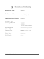
Declaration of Conformity
Manufacturer's Name:
Quatech, Inc.
Manufacturer's Address:
662 Wolf Ledges Parkway
Akron, OH 44311 (USA)
Application of Council Directive:
89/336/EEC
Standards to which
Conformity is Declared:
* EN50081-1
(EN55022)
* EN50082-1
(IEC 801-2, IEC 801-3, & IEC 801-4)
Type of Equipment:
Information Technology Equipment
Equipment Class:
Commercial, Residential, & Light
Industrial
Product Name:
PCMCIA Card
Model Number :
SSP-100
SSP-200/300 User's Manual
3
Table of Contents
1 . Introduction . . . . . . . . . . . . . . . . . . . . . . . . . . . . . . . . . . . . . . . . . . . . . . . . . . . . . . . 1-1
2 . DOS / Windows 3.x Installation . . . . . . . . . . . . . . . . . . . . . . . . . . . . . . . . 2-1
3
4
5
6
7
2.1 SSP-100 Client Driver for DOS . . . . . . . . . . . . . . . . . . . . . . . . . . . . . . . . . . . . . . . . . 2-2
2.1.1 Client Driver Installation . . . . . . . . . . . . . . . . . . . . . . . . . . . . . . . . . . . . . . . . . 2-2
2.1.2 Command Line Options . . . . . . . . . . . . . . . . . . . . . . . . . . . . . . . . . . . . . . . . . 2-3
2.1.3 Common Problems . . . . . . . . . . . . . . . . . . . . . . . . . . . . . . . . . . . . . . . . . . . . . . 2-7
2.2 SSP-100 Enabler for DOS . . . . . . . . . . . . . . . . . . . . . . . . . . . . . . . . . . . . . . . . . . . . . . 2-8
2.2.1 Command Line Options . . . . . . . . . . . . . . . . . . . . . . . . . . . . . . . . . . . . . . . . . 2-9
2.2.2 Common Problems . . . . . . . . . . . . . . . . . . . . . . . . . . . . . . . . . . . . . . . . . . . . . 2-13
. Windows 95, 98, 2000, ME, NT Installation . . . . . . . . . . . . . . . . . . . . 3-1
3.1 Installing a SSP-100 Under Windows 95, 98, ME, 2000. . . . . . . . . . . . . . . . . . . . . 3-1
3.2 SSP-100 Resource Settings in Windows . . . . . . . . . . . . . . . . . . . . . . . . . . . . . . . . . 3-4
3.2.1 Viewing Resource Settings with Device Manager . . . . . . . . . . . . . . . . . . . . 3-4
3.2.2 Changing Resource Settings with Windows 95, 98, ME Device
Manager . . . . . . . . . . . . . . . . . . . . . . . . . . . . . . . . . . . . . . . . . . . . . . . . . . . . . . . . . . . . 3-6
3.2.3 Changing Resource Setting with Window 2000 Device Manager . . . . . . . 3-7
3.3 Common Problems . . . . . . . . . . . . . . . . . . . . . . . . . . . . . . . . . . . . . . . . . . . . . . . . . 3-11
3.4 Installing SSP-100 under Windows NT . . . . . . . . . . . . . . . . . . . . . . . . . . . . . . . . 3-12
. Windows CE . . . . . . . . . . . . . . . . . . . . . . . . . . . . . . . . . . . . . . . . . . . . . . . . . . . . . . . 4-1
OS/2 Installation . . . . . . . . . . . . . . . . . . . . . . . . . . . . . . . . . . . . . . . . . . . . . . . . . . . 4-4
5.1 Command Line Options . . . . . . . . . . . . . . . . . . . . . . . . . . . . . . . . . . . . . . . . . . . . . . 4-5
5.1.1 Configuring With "System Assigned" Resources . . . . . . . . . . . . . . . . . . . . 4-5
5.1.2 Configuring With "User Assigned" Resources . . . . . . . . . . . . . . . . . . . . . . . 4-5
5.1.3 Advanced Configuration Topics . . . . . . . . . . . . . . . . . . . . . . . . . . . . . . . . . . 4-7
5.2 Monitoring The Status Of PCMCIA Cards . . . . . . . . . . . . . . . . . . . . . . . . . . . . . . . 4-8
. External Connections . . . . . . . . . . . . . . . . . . . . . . . . . . . . . . . . . . . . . . . . . . . . . 5-1
. Specifications . . . . . . . . . . . . . . . . . . . . . . . . . . . . . . . . . . . . . . . . . . . . . . . . . . . . . . 6-1
SSP-200/300 User's Manual
4
SSP-200/300 User's Manual
5
1. Introduction
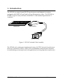
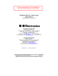
The SSP-100 is a single channel RS-232 asynchronous serial adapter for systems
equipped with PCMCIA Type II and/or Type III expansion sockets. The SSP-100 is a
PCMCIA Type II (5 mm) card and is PCMCIA PC Card Standard Specification 2.1
compliant.
PCMCIA Card
Cable Assembly
Standard D-9 Male
Figure 1. SSP-100 Card and Cable Assembly
The SSP-100 unit's serial port is implemented using a 16C550 Universal Asynchronous
Receiver/Transmitter (UART), which is the recommended communications interface
for multitasking environments and with applications involving high data transfer rates.
SSP-100 User's Manual
1-1
(This page intentionally left blank.)
SSP-100 User's Manual
1-2
2. DOS / Windows 3.x Installation
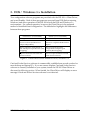
Two configuration software programs are provided with the SSP-100: a Client Driver,
and a card Enabler. Both of these programs are executed from DOS (before entering
Windows) and allow operation of the SSP-100 in both the DOS and Windows 3.x
environments. For optimal operation, however, the Client Driver is the preferred
method of installation and configuration. The table below highlights the differences
between these programs.
Client Driver (recommended)
File type: DOS device driver
Enabler (not recommended)
File type: DOS executable
Interfaces to PCMCIA Card and Socket Interfaces directly to Intel 82365SL and
Services software (PCMCIA host
other PCIC compatible PCMCIA host
adapter independent)
adapters
Allows automatic configuration of
Does not support automatic
SSP-100 adapters upon insertion (Hot configuration of adapters upon
Swapping)
insertion (Hot Swapping)
Requires PCMCIA Card and Socket
Services software
Does not require PCMCIA Card and
Socket Services software
Figure 2. Client Driver versus Enabler for DOS/Windows 3.x.
Card and Socket Services software is commercially available from several vendors for
most desktop and laptop PCs. If you are unsure whether Card and Socket Services
software is currently installed on your system, install the SSP-100 Client Driver as
discussed in following section. When loaded, the Client Driver will display an error
message if Card and Socket Services software is not detected.
SSP-100 User’s Manual
2-1
2.1 SSP-100 Client Driver for DOS
In order to use the SSP-100 Client Driver, the system must be configured with Card and
Socket Services software. Card and Socket Services software is not provided with the
SSP-100 but is available from Quatech.
IMPORTANT:
Some versions of Card and Socket Services dated before
1993 do not support general purpose I/O cards. If after
careful installation of the Client Driver the adapter does
not configure or operate properly, an updated version of
Card and Socket Services may be required.
2.1.1 Client Driver Installation
The following procedure is used to install the SSP-100 Client Driver:
1. Copy the Client Driver from the SSP-100 distribution diskette onto the
system's hard drive.
2. Using an ASCII text editor, open the system's CONFIG.SYS file located in the
root directory of the boot drive.
3. Locate the line(s) in the CONFIG.SYS file where the Card and Socket Services
software is installed.
4. AFTER the line(s) installing the Card and Socket Services software, add the
following line to the CONFIG.SYS file:
DEVICE = drive:\path\
SSP100CL.SYS options
where options are the SSP-100 Client Driver
command line options discussed on the following pages.
5. Save the CONFIG.SYS file and exit the text editor.
6. Insert the SSP-100 into one of the system's PCMCIA slots.
NOTE: Since the SSP-100 Client Driver supports "Hot Swapping", it is not
necessary to have the SSP-100 installed when booting the system. By inserting
the card before booting, however, the Client Driver will report the adapter
configuration during the boot process thereby verifying the changes made to the
CONFIG.SYS.
7. Reboot the system and note the message displayed when the SSP-100 Client
Driver is loaded. If the Client Driver reports an "invalid command line
option", correct the entry in the CONFIG.SYS file and reboot the system
again. If the Client Driver reports "Card and Socket Services not found", a
SSP-100 User’s Manual
2-2
version of Card and Socket Services must be installed on the system or the
SSP-100 Enabler program must be used to configure the adapter. If the Client
Driver reports the desired adapter configuration, the installation process is
complete and the SSP-100 may be removed and/ or inserted from the system
as desired. On each insertion into the PCMCIA socket, the SSP-100 will be
automatically reconfigured according to the command line options.
2.1.2 Command Line Options
The SSP-100 Client Driver accepts up to eight command line arguments from the user to
determine the configuration of the SSP-100. If any arguments are provided, the Client
Driver will attempt to configure any SSP-100 with the options specified in the order
they are entered on the command line. Each argument must be enclosed in parenthesis
and must be separated from other arguments by a space on the command line. Within
each argument, any or all of the following parameters may be specified using a comma
(no spaces) to separate each parameter:
Ssocket
specifies which PCMCIA socket the SSP-100 must be inserted into for this
configuration argument to be used. socket must be in the range 0 - 15. If this
option is omitted, the configuration argument will apply to SSP-100 inserted
into any socket
Baddress specifies a the base I/O address of the SSP-100 in hexadecimal. This address
must reside on an even 8-byte boundary. If this option is omitted, a base
address will be assigned by Card and Socket Services. The “A” switch must
not be used when using this command.
Iirq
specifies the interrupt level (IRQ) of the SSP-100 in decimal. irq must be one
of the following values: 3, 4, 5, 7, 9, 10, 11, 12, 14, 15, or 0 if no IRQ is desired.
If this option is omitted, an interrupt level will be assigned by Card and
Socket Services. The “A” switch must not be used when using this
command.
Ebios
specifies which location the configured SSP-100 will be placed in the BIOS
equipment list. Valid numbers are 1-4. If this option is omitted, the SSP-100
will not appear in the BIOS equipment list. If no number is specified, the
SSP-100 will be placed in the next available location in the BIOS equipment
list. The “A” switch must not be used when using this command.
Acom
specifies which Logical COM port the SSP-100 will be configured. Valid
COM port numbers would be 1-4. The BIOS Equipment list will be
automatically updated, so the E command is not required when using this
SSP-100 User’s Manual
2-3
option. If no number is specified, the SSP-100 will be configured as the next
available COM Port using the standard base address and IRQ settings for
that COM port. If this option is omitted, the user must either specify a base
address or IRQ setting for the SSP-100 or allow Card and Socket Services to
select a base address and IRQ to configure the card. When the “A”
command is used, the “B”, “I”, and “E” commands must not be used.
2.1.2.1 Example 1
DEVICE = C:\SSP-100\SSP100CL.SYS
In example 1, no command line arguments are specified. The Client Driver will
configure a SSP-100 inserted into any socket with a base address and IRQ assigned by
Card and Socket Services. The BIOS equipment list will not be updated.
2.1.2.2 Example 2
DEVICE = C:\SSP-100\SSP100CL.SYS (b290,i11)
In example 2, a single command line argument is provided. The Client Driver will
attempt to configure a SSP-100 inserted into any socket with a base address of 290H and
IRQ 11. The BIOS equipment list will not be updated. If address 290H or IRQ 11 is
unavailable, the SSP-100 will not be configured.
2.1.2.3 Example 3
DEVICE = C:\SSP-100\SSP100CL.SYS (s0,b300,i5)
In example 3, a single command line argument is provided. The Client Driver will
attempt to configure a SSP-100 inserted into socket 0 with a base address of 300H and
IRQ 5. The BIOS equipment list will not be updated. If address 300H or IRQ 5 is
unavailable, the SSP-100 will not be configured. In addition, if a SSP-100 is inserted
into any other socket, it will not be configured.
2.1.2.4 Example 4
DEVICE = C:\SSP-100\SSP100CL.SYS (i5,b300)
In example 4, a single command line argument is provided. Because the parameter
order is not significant, the Client Driver will attempt to configure a SSP-100 inserted
into any socket with a base address of 300H and IRQ 5. The BIOS equipment list will
not be updated. If address 300H or IRQ 5 is unavailable, the SSP-100 will not be
configured.
2.1.2.5 Example 5
SSP-100 User’s Manual
2-4
DEVICE = C:\SSP-100\SSP100CL.SYS (b300,i5) (i10) ( )
In example 5, three command line arguments are provided. The Client Driver will first
attempt to configure a SSP-100 inserted into any socket with a base address of 300H and
IRQ 5. The BIOS equipment list will not be updated. If address 300H or IRQ 5 is
unavailable, the Client Driver will proceed to the second command line argument and
attempt to configure the card with a base address assigned by Card and Socket Services
and IRQ 10. If IRQ 10 is also unavailable, the Client Driver will proceed to the third
command line argument and attempt to configure the SSP-100 with a base address and
an IRQ assigned by Card and Socket Services.
2.1.2.6 Example 6
DEVICE = C:\SSP-100\SSP100CL.SYS (b300,i5) ( ) (i10)
In example 6, the three command line arguments of example 5 have been rearranged.
The Client Driver will first attempt to configure a SSP-100 inserted into any socket with
a base address of 300H and IRQ 5. The BIOS equipment list will not be updated. If
address 300H or IRQ 5 is unavailable, the Client Driver will proceed to the second
command line argument and attempt to configure the card with a base address and IRQ
assigned by Card and Socket Services. Since the second command line argument
includes all available address and IRQ resources, the third command line argument
will never be reached by the Client Driver. It is the user's responsibility to place the
command line arguments in a logical order.
SSP-100 User’s Manual
2-5
2.1.2.7 Example 7
DEVICE = C:\SSP-100\SSP100CL.SYS (s0,b300,i5) (s1,b340,i10)
The type of configuration shown in example 7 may be desirable in systems where more
than one SSP-100 is to be installed. In this example, the Client Driver will attempt to
configure a SSP-100 inserted into socket 0 with a base address of 300H and IRQ 5. If the
SSP-100 is inserted into socket 1, the Client Driver will attempt to configure it with base
address 340H and IRQ 10. This allows the user to force the SSP-100's address and IRQ
settings to be socket specific which may simplify cable connections and software
development. As in the previous examples, however, if the requested address or
interrupt resources are not available, the SSP-100 will not be configured.
2.1.2.8 Example 8
DEVICE=C:\SSP-100\SSP100CL.SYS (s0,b300,i5,e3)
In Example 8, the Client Driver will attempt to configure an SSP-100 into socket 0 with a
base address of 300H and IRQ 5. The COM 3 spot of the BIOS Equipment list will be
occupied with the SSP-100. If the requested socket, base address or interrupt resources
are not available, the SSP-100 will not be configured and no update of the equipment
list will take place. If the requested spot in the BIOS equipment list is not available, but
the requested socket, base address, and IRQ are available, the SSP-100 will be
configured but an error message will appear stating that no update of the equipment
list can take place.
2.1.2.9 Example 9
DEVICE=C:\SSP-100\SSP100CL.SYS (s0,a3)
In Example 9, the Client Driver will attempt to configure an SSP-100 into socket 0 with
the COM 3 standard address of 3E8H and IRQ 4. The COM 3 spot of the BIOS
equipment list will be updated automatically. If the requested socket is unavailable, or
the COM 3 resource settings are unavailable, the SSP-100 will not be configured and no
update of the BIOS equipment list will be made. If the requested spot in the BIOS
equipment list is not available, but the requested socket, base address, and IRQ are
available, the SSP-100 will be configured but an error message will appear stating that
no update of the equipment list can take place.
SSP-100 User’s Manual
2-6
2.1.3 Common Problems
Generic Client Drivers:
Many Card and Socket Services packages include a generic client driver (or
SuperClient) which configures standard I/O devices. If one of these generic client
drivers is installed, it may configure the SSP-100 causing the SSP-100 client driver to fail
installation. In these cases, the user should do one of the following:
1. modify the operation of the generic client driver to disable the configuration
of modem/serial port cards. Consult the Card and Socket Services
documentation for availability and details of this feature.
2. place the SSP-100 client driver before the generic client driver in the
CONFIG.SYS.
Available Resources:
One function of the Card and Socket Services software is to track which system
resources (memory addresses, I/O addresses, IRQs, etc.) are available for assignment
to inserted PCMCIA cards. Sometimes, however, the Card Services software assumes
or incorrectly determines that a particular resource is used when it is actually available.
Most Card and Socket Services generate a resource table in a file (typically in the form
of an .INI file) which the user can modify to adjust the available system resources.
Consult the Card and Socket Services documentation for availability and details of this
feature.
Multiple Configuration Attempts:
Some Card and Socket Services have a setting which aborts the configuration process
after a single configuration failure (such as a request for an unavailable resource). The
user should change this setting to allow for multiple configuration attempts. Consult
the Card and Socket Services documentation for availability and details of this feature.
Older Versions of Card and Socket Services:
Some versions of Card and Socket Services dated before 1993 do not support general
purpose I/O cards. If after careful installation of the Client Driver the SSP-100 does not
configure or operate properly, an updated version of Card and Socket Services may be
required. Card and Socket Services software is available from Quatech.
SSP-100 User’s Manual
2-7
2.2 SSP-100 Enabler for DOS
For systems that are not operating PCMCIA Card and Socket Services software, the
SSP-100 DOS Enabler may be used to enable and configure the adapter. This Enabler,
SSP100EN, will operate on any DOS system using an Intel 82365SL or PCIC compatible
PCMCIA host adapter including the Cirrus Logic CL-PD6710 / 6720, the VLSI
VL82C146, and the Vadem VG-365 among others.
IMPORTANT:
In order to use the SSP-100 Enabler for DOS, the system
MUST NOT be configured with Card and Socket Services
software. If a Card and Socket Services software is installed,
the SSP-100 Enabler may interfere with its operation and
with the device(s) it controls.
The SSP-100 Enabler does not support automatic configuration of adapters upon
insertion, more commonly referred to as "Hot Swapping". This means the adapter must
be installed in one of the system's PCMCIA sockets before executing SSP100EN. If
more than one adapter is installed in a system, the Enabler must be executed separately
for each adapter. Furthermore, SSP100EN should be executed to release the resources
used by the adapter before it is removed from the PCMCIA socket. Since PCMCIA
adapters do not retain their configuration after removal, any adapter that is removed
from the system must be reconfigured with the Enabler after re-inserting it into a
PCMCIA socket.
IMPORTANT:
The Enabler requires a region of high DOS memory when
configuring a SSP-100 This region is 1000H bytes (4KB) long
and by default begins at address D0000H (the default address
may be changed using the "W" option). If a memory manager
such as EMM386, QEMM, or 386Max is installed on the system,
this region of DOS memory must be excluded from the memory
manager's control. Consult the documentation provided with
the memory manager software for instructions on how to
exclude this memory region.
SSP-100 User’s Manual
2-8
2.2.1 Command Line Options
To configure a SSP-100 in the system, the Enabler requires one command line argument
from the user to determine the configuration of the card. This argument must be
enclosed in parentheses and within the argument, any or all of the following
parameters may be specified using a comma (no spaces) to separate each parameter:
Ssocket
specifies which PCMCIA socket the SSP-100 must be inserted into for this
configuration argument to be used. socket must be in the range 0 - 15. This
option is required if the 'R' option is not used.
Baddress specifies the base I/O address of the SSP-100 in hexadecimal. This address
must reside on an even 8-byte boundary. This option is required if the 'R'
option is not used.
Iirq
specifies the interrupt level (IRQ) of the SSP-100 in decimal. irq must be one
of the following values: 3, 4, 5, 7, 9, 10, 11, 12, 14, 15, or 0 if no IRQ is desired.
This option is required if the 'R' option is not used.
Waddress specifies the base address of the memory window required to configure the
SSP-100. Set address = D0 for a memory window at segment D000, address
= D8 for a memory window at segment D800, etc. Valid settings for address
are C8, CC, D0, D4, D8, and DC. If this option is omitted, a memory window
at segment D000 will be used.
Ebios
specifies which location the configured SSP-100 will be placed in the BIOS
equipment list. Valid numbers are 1-4. If this option is omitted, the SSP-100
will not appear in the BIOS equipment list. If no number is specified, the
SSP-100 will be placed in the next available location in the BIOS equipment
list. The “A” switch must not be used when using this command.
Acom
specifies which Logical COM port the SSP-100 will be configured. Valid
COM port numbers would be 1-4. The BIOS Equipment list will be
automatically updated, so the E command is not required when using this
option. If no number is specified, the SSP-100 will be configured as the next
available COM Port using the standard base address and IRQ settings for
that COM port. If this option is omitted, the user must either specify a base
address or IRQ setting for the SSP-100 or allow Card and Socket Services to
select a base address and IRQ to configure the card. When the “A”
command is used, the “B”, “I”, and “E” commands must not be used.
SSP-100 User’s Manual
2-9
Before removing a SSP-100 from its PCMCIA socket, the Enabler should be executed to
free the system resources allocated when the card was installed. For this operation the
Enabler provides on additional command line option:
R
instructs the enabler to release the resources previously allocated to the
SSP-100. When the 'R' option is used, any settings specified by the 'B', and 'I'
options are ignored. The BIOS equipment list WILL NOT be cleared of the
SSP-100 upon execution of the release command.
2.2.1.1 Example 1
SSP100EN
In example 1, no command line argument is specified. The Enabler will report an error
and display the proper usage of the command.
2.2.1.2 Example 2
SSP100EN (s0,b300,i5)
In example 2, the Enabler will configure the SSP-100 in socket 0 with a base address of
300H and IRQ 5 using a configuration memory window at segment D000.
2.2.1.3 Example 3
SSP100EN (i10,b340,s1)
In example 3, the Enabler will configure the SSP-100 in socket 1 with a base address of
340H and IRQ 10 using a configuration memory window at segment D000.
SSP-100 User’s Manual
2-10
2.2.1.4 Example 4
SSP100EN (s0,b300,i3,wd8)
In example 4, the Enabler will configure the SSP-100 in socket 0 with a base address of
300H and IRQ 3 using a configuration memory window at segment D800.
2.2.1.5 Example 5
SSP100EN (i5,b340,s1)
In example 2, the Enabler will configure the SSP-100 in socket 1 with a base address of
340H and IRQ 5 using a configuration memory window at segment D000.
2.2.1.6 Example 6
SSP100EN (s0,b300,i5,r)
In example 6, the Enabler will release the configuration used by the SSP-100 in socket 0
using a configuration memory window at segment D000. The base address and IRQ
parameters are ignored and may be omitted.
2.2.1.7 Example 7
SSP100EN (s1,r,wcc)
In example 7, the Enabler will release the configuration used by the SSP-100 in socket 1
using a configuration memory window at segment CC00.
2.2.1.8 Example 8
SSP100EN (s0,b300,i5,e3)
In Example 8, the Client Driver will attempt to configure an SSP-100 into socket 0 with a
base address of 300H and IRQ 5. The COM 3 spot of the BIOS Equipment list will be
occupied with the SSP-100. If the requested socket, base address or interrupt resources
are not available, the SSP-100 will not be configured and no update of the equipment
list will take place. If the requested spot in the BIOS equipment list is not available, but
the requested socket, base address, and IRQ are available, the SSP-100 will be
configured but an error message will appear stating that no update of the equipment
list can take place.
2.2.1.9 Example 9
SSP-100 User’s Manual
2-11
SSP100EN (s0,a3)
In Example 9, the Client Driver will attempt to configure an SSP-100 into socket 0 with
the COM 3 standard address of 3E8H and IRQ 4. The COM 3 spot of the BIOS
equipment list will be updated automatically. If the requested socket is unavailable, or
the COM 3 resource settings are unavailable, the SSP-100 will not be configured and no
update of the BIOS equipment list will be made. If the requested spot in the BIOS
equipment list is not available, but the requested socket, base address, and IRQ are
available, the SSP-100 will be configured but an error message will appear stating that
no update of the equipment list can take place.
SSP-100 User’s Manual
2-12
2.2.2 Common Problems
Memory Range Exclusion:
The Enabler requires a region of high DOS memory when configuring a SSP-100. This
region is 1000H bytes (4KB) long and by default begins at address D0000H (the default
address may be changed using the "W" option). If a memory manager such as
EMM386, QEMM, or 386Max is installed on the system, this region of DOS memory
must be excluded from the memory manager's control. Consult the documentation
provided with the memory manager software for instructions on how to exclude this
memory region.
Furthermore, some systems use the high memory area for BIOS shadowing to improve
overall system performance. In order for the Enabler to operate, any BIOS shadowing
must be disabled in the address range specified for the configuration window. BIOS
shadowing can usually be disabled through the system's CMOS setup utility.
Socket Numbers:
The Enabler requires the SSP-100's socket number to be specified on the command line
and the SSP-100 must be inserted into the socket before the Enabler is invoked. Some
vendors number their sockets from 1 to N while other vendors number their sockets
from 0 to N-1. For the SSP-100 Enabler, the lowest socket number in the system is
designated socket 0.
Card and Socket Services Software:
In order to use the SSP-100 Enabler for DOS, the system MUST NOT be configured with
Card and Socket Services software. If a Card and Socket Services software is installed,
the SSP-100 Enabler may interfere with its operation and with the device(s) it controls.
For systems configured with Card and Socket Services, the SSP-100 Client Driver is the
recommended method of configuration.
SSP-100 User’s Manual
2-13
(This Page Left Intentionally Blank)
SSP-100 User’s Manual
2-14
3. Windows 95, 98, 2000, ME, NT Installation
To allow easy configuration of the SSP-100, a Windows "INF" configuration file has
been written for the hardware.
3.1 Installing a SSP-100 Under Windows 95, 98, ME, 2000.
1. Insert the SSP-100 into any available PC Card socket.
2. The first time a new PC Card type is installed the New Hardware Found
window opens. After this first installation Windows will automatically
detect and configure the card. If the New Hardware Found window does
not open, then skip to the next section, “SSP-100 Resource Settings".
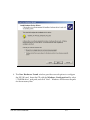
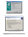
3. The New Hardware Found window provides several options to configure
the SSP-100 card. Click the "Search for the best driver for your device"
option button. Click "Next" to continue.
Figure 3. Windows 95,98, ME New Hardware Wizard (Search for the best
driver...)
SSP-100 User’s Manual
3-1
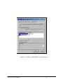
4. The New Hardware Found window provides several options to configure
the SSP-100 card. Insert the CD with the Windows Configuration file, select
“CD-ROM drive” and path, and click "Next". Windows will browse the path
for the necessary files.
SSP-100 User’s Manual
3-2
Figure 5. Windows 95, 98, ME Add New Hardware Wizard
5. During the installation process, it may be required to supply the computer
Figure 6. Windows 2000 New Hardware Wizard
SSP-100 User’s Manual
3-3
with the Windows CD or installation diskettes. The SSP-100's serial devices will
require the file "SERIALUI.DLL". Insert the CD or diskette and click "OK".
IMPORTANT NOTE:
If the user already has these files installed on the
computer, or if the installation disks are unavailable, it
may not be necessary to supply the computer with the
Windows CD or installation diskettes. If prompted for the
disks, click “OK”. A dialog box with an option to skip
will appear. Click the “Skip” button and the files will not
be installed. If these files exist in the windows system
directory, those files will be used.
The SSP-100 PC Card should now be configured. The default configuration for the
SSP-100 is a base address and IRQ assigned by Windows.
3.2 SSP-100 Resource Settings in Windows
Windows maintains a registry of all known hardware installed within the computer.
Inside this hardware registry Windows keeps track of all the computer's resources,
such as base I/O addresses, IRQ levels, and DMA channels. In the case of a PC Card
(PCMCIA) type board, Windows configures the new hardware using free resources it
finds within the hardware registry, and updates the registry automatically.
To view and / or edit hardware devices in Windows use the system Device
Manager. To access Device Manager double click the System icon in the Windows
control panel, or click the My Computer icon on the Windows desktop with the right
mouse button and select Properties from the pull down menu. Consult Windows
on-line help for details on the use of the Device Manager.
3.2.1 Viewing Resource Settings with Device Manager
1. Start the Windows Device Manager.
2. Double click on the hardware class Ports (Com and LPT) to list hardware
devices in the class.
3. The SSP-100 belongs to this hardware class. The device name for the SSP-100
is Quatech SSP-100: RS-232 Serial Port (see Figure 7. Windows 95, 98
Device Manager{Figure 8. Windows 2000}).
SSP-100 User’s Manual
3-4
4. Open the Properties dialog for the SSP-100 device, then click the Resources
tab to view the Input/Output Range and Interrupt Request resource
allocations.
5. Use the COM Port device names (COM2, COM4, etc.) to access any of the
particular serial ports on the SSP-100. This name is required by a Windows
application when accessing a particular port.
Figure 7. Windows 95, 98,ME Device Manager
SSP-100 User’s Manual
3-5
Figure 8. Windows 2000 Device Manager
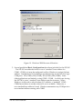
3.2.2 Changing Resource Settings with Windows 95, 98, ME Device
Manager
1. Start the Windows Device Manager.
2. Double click on the hardware class Ports (Com and LPT) to list hardware
devices in the class.
3. The SSP-100 belongs to this hardware class. The device name for the SSP-100
is :Quatech SSP-100: RS-232 Serial Port.
4. Open the Properties dialog for the SSP-100 device, then click the Resources
tab to view the Input/Output Range and Interrupt Request resource
allocations. (see Figure 9. Windows 95, 98, ME Resource Allocation).
SSP-100 User’s Manual
3-6
3.2.3 Changing Resource Setting with Window 2000 Device
Manager
1. Start the Windows Device Manager.
2. Double click on the hardware class Ports (Com and LPT) to list hardware
devices in the class.
3. The SSP-100 belongs to this hardware class. The device name for the SSP-100
is :Quatech PCMCIA Serial Port.
4. Open the Properties dialog for the SSP-100 device, then click the Resources
tab to view the Input/Output Range and Interrupt Request resource
allocations. (see Figure 10. Windows 2000 Resource Allocation).
SSP-100 User’s Manual
3-7
Figure 9. Windows 95,98,ME Resource Allocation
SSP-100 User’s Manual
3-8
Figure 10. Windows 2000 Resource Allocation
5. Several predefined Basic Configurations have been included for the SSP-100
. The SSP-100 can either be forced to use a “standard” base address for
COM1 - COM4, or it may be configured to allow Windows to assign the base
address. Standard base I/O addresses are defined only for the first four logic
COM ports: 3F8 (COM1), 2F8 (COM2), 3E8 (COM3), 2E8 (COM4). Some
older applications are limited to using COM1 - COM4 , in which case forcing
the SSP-100 to use a “standard” base address may be necessary. When
Windows is allowed to select the base I/O address, a “standard” COM1 COM4 base address is usually selected if one is available. Otherwise, a
non-standard base address is used. Windows enumerates any COM port at a
non-standard address starting with COM5.
SSP-100 User’s Manual
3-9
6. Select a Basic Configuration that displays "No conflicts" in the bottom
display region titled Conflicting Device List from the drop down list. Some
applications may not be able to access ports higher than COM4. To use the
SSP-100 PCMCIA serial ports with these applications you might be forced to
remove other serial communications devices from your system.
7. Windows should have chosen an available Interrupt Request setting
automatically when the I/O address range was configured by a Basic
Configuration selection. This default Interrupt Request setting should not
need changed as long as "No conflicts" is displayed in the bottom display
region titled Conflicting Device List. If you are satisfied with Windows
selection then skip the next step.
8. To modify the Interrupt Request setting click the resource name and click
the Change Setting button. An Edit Resource window will open up. Inside
this window click on the up/down arrows to the right of the Interrupt
Request value. This scrolls you through all of the allowable resources for
your hardware. Pay attention to the conflict information at the bottom of the
window. Do not select a value that causes a conflict with any other installed
hardware.
9. If any changes have been made to the SSP-100’s configuration the card will
automatically be reconfigured to the new resources specified. Any time a
PCMCIA card of this type is inserted Windows will attempt to configure the
card at these resource settings. Click the Use Automatic Settings box to
reset the SSP-100 card for automatic configuration.
SSP-100 User’s Manual
3-10
3.3 Common Problems
Basic Configuration List Not Available:
A problem noted on some systems is after a basic configuration has been manually
selected is the basic configurations list for the SSP-100 is no longer available. The
solution to this problem is to check the “Use Automatic Settings” box and allow
Windows to reconfigure the SSP-100 card. The basic configurations list should once
again be visible.
Base I/O Address Resource Modification Not Allowed:
The SSP-100 can either be forced to use a “standard” base address for COM1 - COM4,
or it may be configured to allow Windows to assign the base address. Windows will
not allow the base I/O address resource to be modified if the SSP-100 is configured to
use a “standard” base address, since it is being forced to a certain value by definition.
The solution to enabling a user defined I/O address resource is to select a basic
configuration which allows Windows (and the user) to assign the base address.
SSP-100 User’s Manual
3-11
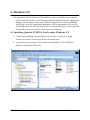
3.4 Installing SSP-100 under Windows NT
To allow easy configuration of the DSP-100 the Quatech Device Manager for Windows
NT has been written for the hardware. This configuration utility supports the DSP-100
only in block addressing mode.
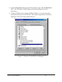
To begin the installation, open Windows Explorer and search for the ‘Setup.exe’
command to install the Quatech Device Manager. <See following Windows Explorer
figure.> (D:\Serial Port Adapters\Drivers\Windows NT 4.0 for PCI, PCMCIA,ISA).
Once the installation is complete an icon will be placed on the desktop.
Windows NT Explorer
SSP-100 User’s Manual
3-12
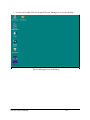
1. Locate and double click the Quatech Device Manager icon on the desktop
Device Manager Icon on Desktop
SSP-100 User’s Manual
3-13
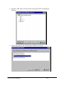
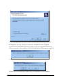
2. Click the ‘Add’ button at the bottom of the Quatech Device Manager
Window.
3. Follow the steps for the ‘Add Quatech Hardware Wizard’.
SSP-100 User’s Manual
3-14
4. Complete the final steps of the installation, insert the PCMCIA Card and
reboot the computer.
v Additional help is available online
The PCMCIA PC Card should now be configured. In the future, Windows NT will
automatically recognize and configure the DSP-100.
Note: Windows NT does not support ‘Plug and Play’ for PCMCIA cards. The PCMCIA
Card must be inserted prior to starting Windows NT and can not be removed and
reinserted while Windows NT is running.
SSP-100 User’s Manual
3-15
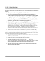
4. Windows CE
The Quatech PCMCIA Windows CD installation copies a multiple device-specific
.cab files and the ini file to your desktop computer and launches the Application
Manger (which resides on the user's desktop computer as a result of installing
Active Sync) with the Application Manager .ini file as a parameter. This in turn
will install the driver onto the Windows CE connected device or if not connected
will install it on the next device connection to the desktop.
4.1 Installing Quatech PCMCIA Cards under Windows CE
1. Connect and establish communication to the device to the desk to using
Active Sync (refer to Active Sync factory documentation
2. Locate and run the setup.exe file located in the Windows CE for PCMCIA
folder on the Quatech COM CD.
SSP-100 User's Manual
4-1
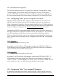
3. The setup program will copy the files to predetermined location, which can
be changed by the user. Click next to proceed.. Installation is now complete.
In the event that installation process took place with out having the Windows CE
device connected to the computer and the install program will prompt the user that
on the next on the next connection the device will complete the installation.
Choose ‘Yes’ on the following window and you installation is now complete.
SSP-100 User's Manual
4-2
SSP-100 User's Manual
4-3
5 OS/2 Installation
In order to use the SSP-100 Client Driver for OS/2, the system must be configured as
follows:
1. The system must be running OS/2 version 2.1 or later.
2. OS/2 PCMCIA Card and Socket Services support must be installed. If
PCMCIA support was not selected when OS/2 was installed, it can be added
using the Selective Install facility in the System Setup folder. On OS/2 2.1
and 2.11, Socket Services must be added separately. The necessary files can
be found on Compuserve in the OS2SUPPORT forum and may be available
elsewhere. These files are not available from Quatech, Inc.
3. Quatech's OS/2 serial port device driver, "QCOM" version 2.01 or later, is not
required but strongly recommended. The SSP-100 can operate with the
standard OS/2 serial port device drivers provided the logical COM port
number does not exceed four. If the logical COM port number is five, then
the "QCOM" driver is required. Quatech, Inc. can not guarantee the
operation of the SSP-100 with any other third party device drivers for OS/2.
4. There must be at least 8 bytes of available I/O space and 1 available IRQ.
After the system has been configured to the above specifications, the SSP-100 Client
Driver may be installed with the following procedure:
1. Copy the OS/2 client driver file from the distribution disk to any convenient
directory on the hard disk.
2. Open the CONFIG.SYS file using any ASCII text editor.
3. Add the following line to the CONFIG.SYS file:
DEVICE =
drive:\path\SSP100.SYS options where options are the SSP-100 OS/2 Client
Driver command line options discussed in the following sections.
4. Save the CONFIG.SYS file, exit the text editor, shutdown the system, and
reboot to activate the changes.
SSP-100 User's Manual
4-4
5.1 Command Line Options
The SSP-100 Client Driver for OS/2 supports two methods of configuration: using
"system assigned" resources and using "user assigned" resources. Both options
provide full PCMCIA compliance and functionality (including "Hot-swapping") but
each has some advantages and disadvantages as discussed in the following sections.
5.1.1 Configuring With "System Assigned" Resources
Allowing the OS/2 Plug-and-Play system to assign the hardware resources to the
SSP-100 is the ideal choice when only OS/2 programs will access the serial ports.
When configuring the hardware, the user simply specifies a list of COM port numbers.
When an SSP-100 is inserted into a PCMCIA socket, the client driver will configure the
card as a COM port, starting with the lowest available port number in the list.
Configuring a SSP-100 with system assigned resources can be a problem, however, if
DOS and/or Windows applications will be accessing the serial ports. This is because
most DOS applications write directly to the communications hardware and the
Windows' Control Panel also wants to know the hardware configuration of the serial
ports. In these cases, the user may want to configure the SSP-100 with "user assigned"
resources.
5.1.1.1 Example 1
DEVICE=C:\SSP-100\SSP100.SYS COM3
In example 1, the Client Driver will attempt to configure the SSP-100 as COM3. If
COM3 already exists in the system, the SSP-100 will not be configured. Furthermore,
only one SSP-100 can be installed in this system.
5.1.1.2 Example 2
DEVICE=C:\SSP-100\SSP100.SYS COM7 COM3
In example 2, the Client Driver will attempt to configure the SSP-100 as COM3 . If
COM3 already exists in the system, the Client Driver will attempt to configure the
SSP-100 as COM7 . If COM7 already exist already exist in the system, the SSP-100 will
not be configured. Up to two SSP-100s can be installed in this system.
5.1.2 Configuring With "User Assigned" Resources
As mentioned in the previous section, allowing the OS/2 Plug-and-Play system to
assign the hardware resources to the SSP-100 is ideal for OS/2 programs but can be a
SSP-100 User's Manual
4-5
problem if DOS and/or Windows applications will be accessing the serial ports. This
is because most DOS applications write directly to the communications hardware and
the Windows Control Panel also wants to know the hardware configuration of the serial
ports. For this reason, the SSP-100 Client Driver allows the user to request specific
hardware settings using a series of command line arguments of the form
(port,address,irq)
port
specifies the beginning COM port number
address specifies the base I/O address of the SSP-100 in hexadecimal and must
reside on an even 8-byte boundary.
irq
specifies the interrupt level (IRQ) of the SSP-100 in decimal. irq must be
one of the following values: 3, 4, 5, 7, 9, 10, 11, 12, 14, or 15.
Each argument must be enclosed in parentheses and must be separated from other
arguments by a space on the command line. Within each argument, the parameters
must be separated using a comma (no spaces).
When an SSP-100 is inserted into a PCMCIA socket, the client driver will configure the
card as a series of COM ports, starting with the lowest available port number in the list.
IMPORTANT:
If the user specified resources are in-use by other devices in
the system, the SSP-100 will not be configured.
5.1.2.1 Example 1
DEVICE=C:\SSP-100\SSP100.SYS (3,100,5)
In example 1, the Client Driver will attempt to configure the SSP-100 as COM3 using
I/O addresses 100-107 hex and IRQ 5. If COM3 already exists, or if the I/O address or
IRQ resources are already in use, the SSP-100 will not be configured. Furthermore,
only one SSP-100 can be installed in this system.
SSP-100 User's Manual
4-6
5.1.2.2 Example 2
DEVICE=C:\SSP-100\SSP100.SYS (7,120,15) (3,300,4)
In example 2, the Client Driver will attempt to configure the SSP-100 as COM3 using
I/O address 300-307 hex and IRQ 4. If COM3 already exists, or if the I/O address or
IRQ resources are already in use, the Client Driver will attempt to configure the
SSP-100 as COM7 using I/O address 120-127 hex and IRQ 15. If COM7 already exists
or if the I/O address or IRQ resources are already in use, the SSP-100 will not be
configured. Up to two SSP-100s can be installed in this system.
5.1.3 Advanced Configuration Topics
For some applications, it may be desirable to specify the resources for one SSP-100
while allowing the OS/2 Plug-and-Play system to assign the hardware resources for
any additional cards. This can be accomplished by mixing the configuration methods
on the SSP-100 Client Driver command line
DEVICE=C:\SSP-100\SSP100.SYS (3,100,5) COM7
It is important to remember that when a SSP-100 is inserted into a PCMCIA socket, the
client driver will configure the card as a series of COM ports, starting with the lowest
available port number in the list.
Another common application requirement is to have a SSP-100 inserted into socket 1 be
configured as COM3 while a SSP-100 inserted into socket 2 be configured as COM7 .
This type of configuration is supported by appending a "=Sx" parameter after any
command line argument.
DEVICE=C:\SSP-100\SSP100.SYS COM3=S1 COM7=S2
DEVICE=C:\SSP-100\SSP100.SYS (3,100,4)=S1 (7,300,3)=S2
SSP-100 User's Manual
4-7
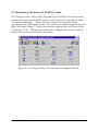
5.2 Monitoring The Status Of PCMCIA Cards
OS/2 Warp provides a utility called "Plug and Play for PCMCIA" that can be used to
monitor the status of each PCMCIA socket. In OS/2 version 2.1, this utility is called
"Configuration Manager". When a SSP-100 is inserted, the Card Type for the
appropriate socket will display "Serial". If the card is successfully configured, the Card
Status will display "Ready". If the card cannot be configured, the Card Status will be
"Not Ready" or "In". The resources claimed by a configured card can be viewed by
double-clicking on that card's line in the window.
Figure 11. OS/2 Plug and Play GUI with properly configured SSP-100.
SSP-100 User's Manual
4-8
(This Page Left Intentionally Blank)
SSP-100 User's Manual
4-9
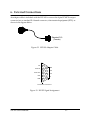
6. External Connections
An adapter cable is included with the SSP-100 to convert the 9-pin PCMCIA output
connector into a standard D-9 female connector, data terminal equipment (DTE), as
shown in the figures below.
Standard D-9
(Female)
Figure 12. SSP-100 Adapter Cable.
CD
1
DATA IN
2
DATA OUT
3
DTR
4
GND
5
6
DSR
7
RTS
8
CTS
9
RI
D-9 Female Connector
Figure 13. RS-232 Signal Assignment.
SSP-100 User’s Manual
5-1
(This page intentionally left blank.)
SSP-100 User’s Manual
5-2
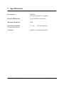
7. Specifications
Bus Interface
PCMCIA
PC Card Standard 2.1 compliant
Physical Dimensions
Type II PCMCIA card (5mm)
Maximum Baud Rate
120K
Power Requirements
25.95 mA (maximum)
+5 volts
Connector
Adapter to standard female D-9
SSP-100 User's Manual
18.85 mA (typical)
6-1
SSP-100
User's Manual
Revision 2.30
September, 2001
P/N 940-0074-230