1
CRHEATER101A00 -- CRHEATER119A00,
CRHEATER264A00 -- CRHEATER269A00,
CRHEATER288A00 -- CRHEATER299A00
CRHEATER301A00, CRHEATER308A00
CRHEATER316A00 -- CRHEATER322A00
CRSINGLE037A00 - CRSINGLE054A00
SMALL ROOFTOP UNITS
ACCESSORY ELECTRIC HEATER
AND SINGLE POINT BOX
ELECTRIC COOLING
AND HEAT PUMP
SELECT 3 to 15 TONS
Installation Instructions
TABLE OF CONTENTS
SAFETY CONSIDERATIONS . . . . . . . . . . . . . . . . . . . . . . . . . 1
PACKAGE USAGE . . . . . . . . . . . . . . . . . . . . . . . . . . . . . . . . . . 2
PACKAGE CONTENTS . . . . . . . . . . . . . . . . . . . . . . . . . . . . . . 2
GENERAL . . . . . . . . . . . . . . . . . . . . . . . . . . . . . . . . . . . . . . . . . 6
GENERAL INSTALLATION SEQUENCE . . . . . . . . . . . . . . . . 9
SECTION 1 INSTALLATION, SMALL--MEDIUM CABINET 10
Installing Single Point Box (CRSINGLE037A00-054A00) . . . . . . . . . . . . . . . . . . . . . . . . . . . . . . . . . . . . . . . 10
Installing Electric Heater (CRHEATER101A00--119A00,
CRHEATER264A00--269A00, 297A00--299A00, 301A00,
308A00, CRHEATER316A00--322A00) . . . . . . . . . . . . . 10
SECTION 2 INSTALLATION, LARGE CABINET (3 OUTDOOR FANS) . . . . . . . . . . . . . . . . . . . . . . . . . . . . . . . . . . . . . 18
Installing Single Point Box (CRSINGLE047A00,
049A00--054A00 . . . . . . . . . . . . . . . . . . . . . . . . . . . . . . . . 18
Installing Electric Heater (CRHEATER288A00-296A00) . . . . . . . . . . . . . . . . . . . . . . . . . . . . . . . . . . . . . . . 20
When working on air-conditioning equipment, observe
precautions in the literature, tags and labels attached to
the unit, and other safety precautions that may apply.
Follow all safety codes. Wear safety glasses and work
gloves.
Recognize safety information. This is the safety-- alert
. When you see this symbol on the unit and in
symbol
instructions or manuals, be alert to the potential for
personal injury.
Understand the signal words DANGER, WARNING, and
CAUTION. These words are used with the safety-- alert
symbol. DANGER identifies the most serious hazards
which will result in severe personal injury or death.
WARNING signifies a hazard which could result in
personal injury or death. CAUTION is used to identify
unsafe practices which may result in minor personal
injury or product and property damage. NOTE is used to
highlight suggestions which will result in enhanced
installation, reliability, or operation.
UNIT POWER SUPPLY WIRING -- ALL UNITS . . . . . . . . . 29
APPENDIX A: CONNECTION FIGURES, AC--1, AC--2 . . . 31
APPENDIX B: CONNECTION FIGURES, AC--3 . . . . . . . . . 42
APPENDIX C: CONNECTION FIGURES, HP--1, HP2 . . . . . 49
APPENDIX D: HEATER DATA . . . . . . . . . . . . . . . . . . . . . . . 67
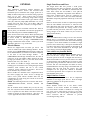
IMPORTANT: Read these instructions completely before
attempting to install this accessory.
SAFETY CONSIDERATIONS
Installation and servicing of air-- conditioning equipment
can be hazardous due to system pressure and electrical
components. Only trained and qualified service personnel
should install, repair, or service air-conditioning
equipment.
Untrained personnel can perform the basic maintenance
functions. All other operations should be performed by
trained service personnel.
!
WARNING
ELECTRICAL SHOCK HAZARD
Failure to follow this warning could result in personal
injury or death.
Turn off all power to unit and install lockout tag.
Power can come to unit from multiple sources. Verify
power is off with a meter or probe.
!
CAUTION
CUT HAZARD
Failure to follow this caution may result in personal
injury. Sheet metal parts may have sharp edges or
burrs. Use care and wear appropriate protective
clothing, safety glasses and gloves when handling
parts and servicing units.
PACKAGE USAGE
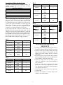
CARRIER MODELS
MODEL NUMBER
CHASSIS
GROUP
UNIT SIZES
50HC
AC --- 2
04--- 14
50HCQ
HP--- 2
04--- 12
50LC
AC --- 3
04--- 12
50TC
AC --- 1
04--- 16
50TCQ
HP--- 1
04--- 14
ELECTRIC HEATERS
CRHEATER288A00--296A00, 299A00,
322A00
QTY
CRHTR,CRSIN
BRYANT MODELS
MODEL NUMBER
CHASSIS
GROUP
UNIT SIZES
548J
HP--- 1
04--- 14
549J
HP--- 2
04--- 12
551J
AC --- 2
558J
AC --- 1
CONTENTS
1
Heater module
1
Heater slide track
4
Screws
1
Wiring label
1
Label, Max Temp/Static
CRSINGLE037A00
ITEM DESCRIPTION
QUANTITY
04--- 14
Single Point Box Housing Assembly
(Height 18--- in/449 mm)
1
04--- 16
Terminal block
1
Conductors, Tap, #10
3
ICP MODELS
MODEL NUMBER
CHASSIS
GROUP
UNIT SIZES
RAH
AC --- 2
036--- 150
RAS
AC --- 1
036--- 180
RHH
HP--- 2
036--- 120
RHS
HP--- 1
036--- 150
AC: Cooling Only (air conditioner)
HP: Heat Pump
1 ---Standard Efficiency
2 --- High Efficiency
3 --- Ultra High Efficiency
Rain shield with conduit seal
1
Screws, #10 x ½--- in
12
Wire ties
7
Tube clamp
1
Seal strip
1
CRSINGLE038A00
ITEM DESCRIPTION
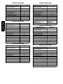
PACKAGE CONTENTS-ELECTRIC HEATERS
CRHEATER101A00--119A00,
CRHEATER264A00--269A00
CRHEATER297A00, 298A00, 301A00,
308A00, CRHEATER316A00--321A00
QTY
CONTENTS
1
Heater module
1
Heater slider track*
4
Screws*
1
Wiring label
1
Red wire (10 gauge){
1
Splice connector{
1
Wire tie{
1
Label, Max Temp/Static
1
Heater Cover**
*Not included with CRHEATER101A00 ---109A00, 297A00, 298A00, 301A00
{Supplied with electric heater packages CRHEATER101A00,
CRHEATER102A00, CRHEATER103B00, and CRHEATER104B00 only.
** Supplied with package CRHEATER301A00 only
QUANTITY
Single Point Box Housing Assembly
(Height 18--- in/449 mm)
1
Terminal block/Fuse holder
1
Fuse block
1
Fuses, 60--- A class RK5
6
Power distribution harness
1
Conductors, Tap, #10
3
Rain shield with conduit seal
1
Screws, #10 x ½--- in
12
Wire ties
7
Tube clamp
1
Seal strip
1
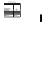
CRSINGLE039A00
ITEM DESCRIPTION
QUANTITY
Single Point Box Housing Assembly
(Height 18--- in/449 mm)
1
Terminal block/Fuse holder
1
Fuse block
2
Fuses, 60--- A class RK5
9
Power distribution harness
1
Conductors, Tap, #10
3
Rain shield with conduit seal
1
Screws, #10 x ½--- in
12
Wire ties
7
Tube clamp
1
Seal strip
1
2
ITEM DESCRIPTION
Single Point Box Housing Assembly
(Height 18--- in/449 mm)
CRSINGLE044A00
QUANTITY
ITEM DESCRIPTION
QUANTITY
1
Single Point Box Housing Assembly
(Height 25--- in/639 mm)
1
Terminal block/Fuse holder
1
Terminal block
1
Fuse block
1
Fuse block
2
Fuses, 60--- A class RK5
4
Fuses, 60--- A class T (600v)
6
Power distribution harness
1
Power distribution harness
1
Conductors, Tap, #10
2
Conductors, Tap, #10
3
Rain shield with conduit seal
1
Rain shield with conduit seal
1
Screws, #10 x ½--- in
12
Screws, #10 x ½--- in
8
Wire ties
7
Wire ties
7
Tube clamp
1
Seal strip
1
Seal strip
1
CRSINGLE045A00
CRSINGLE041A00
ITEM DESCRIPTION
ITEM DESCRIPTION
QUANTITY
QUANTITY
Single Point Box Housing Assembly
(Height 25--- in/639 mm)
1
Single Point Box Housing Assembly
(Height 18--- in/449 mm)
1
Terminal block/fuse holder
1
Terminal block/Fuse holder
1
Fuse block
2
Fuse block
1
Fuses, 60--- A class RK5
9
Fuses, 60--- A class RK5
6
Power distribution harness
1
Power distribution harness
1
Conductors, Tap, #10
6
Conductors, Tap, #10
2
Terminal block (TB10)
2
Rain shield with conduit seal
1
Screws, #8 x ½--- in
2
Screws, #10 x ½--- in
12
Rain shield with conduit seal
1
Wire ties
7
Screws, #10 x ½--- in
8
Tube clamp
1
Wire ties
7
Seal strip
1
Seal strip
1
CRSINGLE042A00
ITEM DESCRIPTION
CRSINGLE046A00
QUANTITY
ITEM DESCRIPTION
QUANTITY
Single Point Box Housing Assembly
(Height 25--- in/639 mm)
1
Single Point Box Housing Assembly
(Height 25--- in/639 mm)
1
Terminal block
1
Terminal block/fuse holder
1
Conductors, Tap, #10
3
Fuse block
3
Rain shield with conduit seal
1
Fuses, 60--- A class RK5
12
Screws, #10 x ½--- in
8
Power distribution harness
1
Wire ties
7
Conductors, Tap, #10
3
Seal strip
1
Rain shield with conduit seal
1
Screws, #10 x ½--- in
8
Wire ties
7
Seal strip
1
CRSINGLE043A00
ITEM DESCRIPTION
QUANTITY
Single Point Box Housing Assembly
(Height 25--- in/639 mm)
1
Terminal block/Fuse holder
1
Fuse block
1
Terminal block (TB--- 10)
CRSINGLE047A00
ITEM DESCRIPTION
QUANTITY
2
Single Point Box Housing Assembly
(Height 33--- in/845 mm)
1
Fuses, 60--- A class RK5
6
Terminal block
1
Power distribution harness
1
Conductors, Tap, #10
3
Conductors, Tap, #10
6
Rain shield, small
1
Screws, #8 x ½--- in
2
Rain shield with conduit seal
1
Rain shield with conduit seal
1
Screws, #10 x ½--- in
8
Screws, #10 x ½--- in
8
Wire ties
7
Wire ties
7
Seal strip
1
Seal strip
1
3
CRHTR,CRSIN
CRSINGLE040A00
CRSINGLE048A00
CRHTR,CRSIN
ITEM DESCRIPTION
CRSINGLE051A00
QUANTITY
ITEM DESCRIPTION
QUANTITY
Single Point Box Housing Assembly
(Height 25--- in/639 mm)
1
Single Point Box Housing Assembly
(Height 33--- in/845 mm)
1
Terminal block
1
Terminal block/fuse holder
1
Fuse block
3
Fuse block
2
Fuses, 60--- A class RK5
9
Fuses, 60--- A class RK5
9
Power distribution harness
1
Power distribution harness
1
Conductors, Tap, #10
3
Conductors, Tap, #10
8
Rain shield with conduit seal
1
Terminal block (TB10)
2
Screws, #10 x ½--- in
8
Screws, #8 x ½--- in
2
Wire ties
7
Rain shield, small
1
Seal strip
1
Rain shield with conduit seal
1
Screws, #10 x ½--- in
8
Wire ties
7
Seal strip
1
CRSINGLE049A00
ITEM DESCRIPTION
QUANTITY
Single Point Box Housing Assembly
(Height 33--- in/845 mm)
1
Terminal block/Fuse holder
1
Fuse block
1
Fuses, 60--- A class RK5
CRSINGLE052A00
ITEM DESCRIPTION
QUANTITY
6
Single Point Box Housing Assembly
(Height 33--- in/845 mm)
1
Power distribution harness
1
Terminal block
1
Conductors, Tap, #10
8
Fuse block
3
Terminal block (TB10)
2
Fuses, 60--- A class T (600v)
9
Screws, #8 x ½--- in
2
Power distribution harness
1
Rain shield, small
1
Conductors, Tap, #10
3
Rain shield with conduit seal
1
Rain shield, small
1
Screws, #10 x ½--- in
8
Rain shield with conduit seal
1
Wire ties
7
Screws, #10 x ½--- in
8
Seal strip
1
Wire ties
7
Seal strip
1
CRSINGLE050A00
ITEM DESCRIPTION
QUANTITY
Single Point Box Housing Assembly
(Height 33--- in/845 mm)
1
Terminal block
CRSINGLE053A00
ITEM DESCRIPTION
QUANTITY
1
Single Point Box Housing Assembly
(Height 33--- in/845 mm)
1
Fuse block
2
Terminal block
1
Fuses, 60--- A class T (600v)
6
Fuse block
4
Power distribution harness
1
Fuses, 60--- A class RK5
12
Conductors, Tap, #10
3
Power distribution harness
1
Rain shield, small
1
Conductors, Tap, #10
8
Rain shield with conduit seal
1
Terminal block (TB10)
2
Screws, #10 x ½--- in
8
Screws, #8 x ½--- in
2
Wire ties
7
Rain shield, small
1
Seal strip
1
Rain shield with conduit seal
1
Screws, #10 x ½--- in
8
Wire ties
7
Seal strip
1
4
ITEM DESCRIPTION
QUANTITY
Single Point Box Housing Assembly
(Height 33--- in/845 mm)
1
Terminal block
1
Fuse block
5
Fuses, 60--- A class RK5
15
Power distribution harness
1
Conductors, Tap, #10
8
Terminal block (TB10)
2
Screws, #8 x ½--- in
2
Rain shield, small
1
Rain shield with conduit seal
1
Screws, #10 x ½--- in
8
Wire ties
7
Seal strip
1
CRHTR,CRSIN
CRSINGLE054A00
5
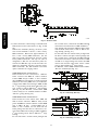
GENERAL
CRHTR,CRSIN
PuronR Units
This installation instruction manual describes the
installation of electric heaters and associated fuse
block/field power termination kits (single point box or
SPB) on small rooftop units in nominal cooling capacities
from 3 to 15 tons. These rooftop units use Puron
refrigerant (R-410A). See Package Usage tables on page
2 for applicable unit models. Unit types include cooling
units (AC) and heat pumps (HP) distributed over several
chassis sizes. Unit types AC-- 1, AC-- 2, HP-- 1, HP-- 2 are
identified. Unit type AC-- 3 consists of a single model —
Carrier 50LC.
This information does not include selection data. Refer to
project plans, job submittals and selection programs for
heater and field power termination/SPB kit usage.
Some electric heaters used on these Puron (R-410A) units
may also be installed in earlier R-22 rooftop units. Refer
to Form 50-8SI or IIK-548-36-49 for installation
instructions on heater packages CRHEATER101A00
through 119A00 with earlier models. Contact your local
distributor office for a copy of this form.
Electric Heaters
Heaters are shipped with one heater per carton. The
carton is marked with a Sales Package Number. On all
heaters except CRHEATER101A00 through 119A00, the
heater Model Number (as marked on the heater infoplate)
is the same as the Sales Package number.
On
CRHEATER101A00 through 119A00 heaters, the value in
position 9 of the part number differs between the sales
package part number (value is 1) and bare heater model
number (value is 0). (See Table 1.)
The heaters are modular in design, with heater frames
holding open coil resistance wires strung through ceramic
insulators, limit switches and one or two control
contactors. Power conductors are attached. One or two
heater modules may be used in a unit.
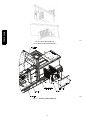
Heater modules are installed in the compartment below
the indoor (supply) fan outlet. Access is through the
indoor access panel. Heater modules slide into the
compartment on tracks along the bottom of the heater
opening. (See Fig. 15.)
NOTE: The following heaters do not use the slide track CRHEATER01A00-- 109A00, 297A00, 298A00, and
301A00.
Not all available heater modules may be used in every
unit. Use only those heater modules that are UL listed for
use in a specific size unit. Refer to the label on the unit
cabinet for the list of approved heaters. (See Fig. 1 and
2.) See Appendix D for electric heater module data.
Single Point Boxes and Fuses
The Single Point Box kits provide a field power
termination location plus an enclosure for heater fuses
when required by code. The SPBs are installed under the
unit’s main control box and include a cover plus all
internal wiring. Minimum components of the SPB are a
field power terminal block with tap conductors (to
connect to the unit’s main control box field terminals).
Maximum component population includes up to five fuse
blocks.
Fuses for electric heater circuits are required and provided
when the unit’s MOCP exceeds 60-A or when the total
heater Full Load Amp value exceeds 48-A. When fuses
are required and provided, the cooling circuit is also
provided with fuse protection; some units require minor
wiring changes in the main control box (see section on
TB10 terminal blocks).
No Fuses
If the unit’s MOCP device rating is 60-A or less, then the
MOCP device is recognized as providing the required
overcurrent protection to the heater and no internal fusing
is required. If two heater modules are installed, a single
point box that contains only a field power terminal block
is required. See tables at the beginning of Appendix A, B
and C for where-used information on the single point
boxes and for connections Figure number.
Units with Factory Installed HACR
The amp rating of the HACR factory installed option is
based on the size, voltage, indoor motor and other
electrical options of the unit as shipped from the factory.
When field installed accessory electric heaters are added
or changed in the unit, the HACR may no longer be of the
proper amp rating and therefore will need to be removed
from the unit. See unit nameplate and label on factory
installed HACR for the amp rating of the HACR that was
shipped with the unit from the factory. See unit
nameplates for the proper fuse, HACR or maximum
over-- current protection device required on the unit with
field installed electric heat.
Single Point Box Contents
See Package Content tables for a list of components
included in each single point box kit. Note the height
differences and their use in specific size units.
Control Wiring
Heater modules contain one or two heater control
contactors. If two heater modules are installed, or a
two-circuit heater module is installed, the cooling unit
(AC type) can be connected for one-stage or two-stage
heating control. On all heat pump units (HP type), all
heater contactors will be connected to provide
second-stage heating control.
6
Table 1 – Heater Model Number
Bare Heater Model
Number
C
R
H
E
A
T
E
R
0
0
1
A
0
0
Heater Sales Package
PNO
Includes:
Bare Heater
Carton and packing
materials
Installation sheet
C
R
H
E
A
T
E
R
1
0
1
A
0
0
MODEL
Carrier
50TC-A06A2A5A0A0A0
Corporation
7310 West Morris Street
Indianapolis, IN 46231 U.S.A.
VOLTS AC
PH
1 208/230
HZ
RLA
LRA
REF. SYSTEM R410A
TEST PRESSURE GAGE
10.7 LBS 4.9
kg HI
COMPR B
LBS
kg LO
COMPR C
LBS
kg
FAN MTR
QTY VOLTS AC
3 60 15.6 110
PH HZ
1 208/230
1 208/230
OUTDOOR
INDOOR
650
450
4482
3103
PSI
PSI
CRHTR,CRSIN
QTY
COMPR A
kPa
kPa
FLA
1 60 1.5
3 60 5.2
PWR.EXH.
CHARGE SYSTEM PER INSTALLATION INSTRUCTIONS
ELC.HEAT
SUITABLE FOR OUTDOOR INSTALLATION
OTHER
POWER
SUPPLY
PERMISSIBLE
VOLTAGE AT UNIT
208/230
DOWN SUPPLY
VOLT
253
3 PH 60
MAX
187
HZ
MIN. CKT.
AMPS
MIN
26.2
MAX FUSE OR HACR
BREAKER PER NEC
MAX OVERCURRENT
PROTECTION DEVICE
MIN CLEARANCE TO COMBUSTIBLE MATERIALS
MINIMUM UNIT DISCONNECT
FLA
LRA
40
-
26
1
25
_____INCHES ______mm.
144
12
305
FOR FIRST _____INCHES______mm.
OF DUCT WHEN ELECTRIC HEATER IS INSTALLED
SIDE SUPPLY
1
25
MIN CLEARANCE TO COMBUSTIBLE MATERIALS _____INCHES
______mm.
12
305
FOR FIRST _____INCHES______mm.
OF DUCT WHEN ELECTRIC HEATER IS INSTALLED
*FOR INSTALLATION ON COMBUSTIBLE FLOORING OR
CLASS A,B, OR C ROOFING MATERIAL
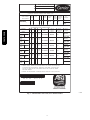
ACCESSORY
HEATER MODEL
NUMBER
CHECK
HERE
VOLTS PH HZ
HEATER
FLA
MIN CKT
AMPS
FUSE OR
HACR
BREAKER
PER NEC
MAXIMUM
OVERCURRENT
PROTECTION
DEVICE
MINIMUM
UNIT
DISCONNECT
SINGLE PT.
BOX MODEL
NUMBER
FLA
LRA
102A
208/ 3 60 13.6/ 26.2/
240
15.6
26.2
40/40
-/-
-
26/26
144/
144
104B
208/ 3 60 21.9/ 33.9/
240
25.3
38.1
40/40
-/-
-
31/35
144/
144
105A
208/ 3 60 33.4/ 48.3/
240
38.5
54.6
50/60
-/-
037
44/50
144/
144
104B+104B
208/ 3 60 43.8/ 61.3/
240
50.5
69.6
70/70
-/-
038
56/64
144/
144
104B+105A
208/ 3 60 55.2/ 75.5/
240
63.8
86.3
80/90
-/-
038
69/79
144/
144
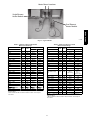
INSTALLER NOTE: 1.INSTALL ACCESS HEATER PER INSTALL INSTR ENCLOSED WITH
SPACE "CHECK HERE" FOR MODEL USED USE MIN CKT AMPS &
CURRENT DEVICE AMPS LISTED FOR HEATER. IF NO HEATER
MARK SPACE "CHECK HERE" FOR NONE.
2.HEATERS ARE MANUFACTURED BY EMERSON HEATING PRODUCTS
HEATER. MARK
MAX OVERIS USED
CAPACITY Btu/Hr
COOLING
59000
CAPACITY kW
17.2
OR TUTCO ELECTRIC.
EER
COP
13
HP HEATING
THIS EQUIPMENT COMPLIES WITH THE
2004 REQUIREMENTS OF ASHRAE 90.1
C10531
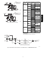
Fig. 1 -- Unit Informative Data Label
7
MODEL
50TC-A06A2A5A0A0A0
REFRIGERANT CHARGE R410A
ELECTRICAL DATA FOR ACCESSORY POWER EXHAUST ONLY
ACCESSORY
POWER EXHAUST
MODEL NUMBER
CHECK
HERE
VOLTS
PH
POWER
EXHAUST
HZ
MIN CKT
AMPS
FLA
FUSE OR
HACR
BREAKER
PER NEC
MAXIMUM
OVERCURRENT
POROTECTION
DEVICE
MINIMUM
UNIT
DISCONNECT
FLA
28.1
CRPWREXH_
40
-/-
28
LRA
146
ELECTRICAL DATA FOR ACCESSORY POWER EXHAUST INSTALLED
CRHTR,CRSIN
IN COMBINATAION WITH ELECTRIC HEATER
ACCESSORY
HEATER MODEL
NUMBER
CHECK
HERE
VOLTS PH HZ HEATER
FLA
FUSE OR
HACR
BREAKER
PER NEC
MIN CKT
AMPS
MAXIMUM
OVERCURRENT
POROTECTION
DEVICE
MINIMUM
UNIT
DISCONNECT
FLA
102A
SINGLE PT
BOX MODEL
NUMBER
208/ 3 60 13.6/
240
15.6
-
28/28
28.1/28.4 40/40
-/-
LRA
146/146
FLA
104B
SINGLE PT
BOX MODEL
NUMBER
208/ 3 60 21.9/
240
25.3
-
33/37
36.3/40.5 40/45
-/-
LRA
146/146
FLA
105A
SINGLE PT
BOX MODEL
NUMBER
208/ 3 60 33.4/
240
38.5
037
47/52
50.6/57.0 60/60
-/-
LRA
146/146
FLA
104B+104B
SINGLE PT
BOX MODEL
NUMBER
208/ 3 60 43.8/
240
50.5
038
-/-
LRA
146/146
FLA
104B+105A
SINGLE PT
BOX MODEL
NUMBER
59/66
63.6/72.0 70/80
208/ 3 60 55.2/
240
63.8
038
72/82
77.9/88.6 80/90
-/-
LRA
146/146
FLA
SINGLE PT
BOX MODEL
NUMBER
LRA
INSTALLER NOTE:
1.INSTALL ACCESS. HEATER AND/OR POWER EXHAUST PER INSTALL INSTR ENCLOSED
WITH HEATER AND POWER EXHAUST. MARKSPACE "CHECK HERE" FOR MODEL USED.
USE MIN CKT AMPS AND MAX OVER CURRENT DEVICE AMPS LISTED FOR HEATER
AND POWER EXHAUST.
2.HEATERS ARE MANUFACTURED BY EMERSON HEATING PRODUCTS OR TUTCO ELECTRIC.
*50TC-A06A2A5A0A0A0*
C10532
Fig. 2 -- Unit Informative Data Label, Power Exhaust Installed
8
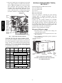
HP--1
Two small terminal blocks (designated TB10) are
included in these single-- point boxes used on select
208/230-- 3-- 60 units.
SPB PNO CRSINGLE_
043A00
045A00
049A00
051A00
053A00
054A00
TB10 is a small single-- pole terminal block, 2-- 1/2-- in. (63
mm) long with seven ¼-- in. male quick-- connect
terminals. One or two terminal blocks are used to aid in
re-- arranging the unit’s base cooling power circuit into two
circuits, each under 60-- A MOCP. On units using both
TB10 blocks, the indoor fan motor is separated into the
second circuit. On units using only a single TB10 block,
Compressor 2 is separated into the second circuit.
On the largest units and on all AC-- 3 (50LC) units, the
TB10 blocks are not used and may be discarded. The tap
conductors from fuse blocks FU2 and FU3 are connected
in parallel to the main control box’s power terminal block.
See unit-- SPB connection figures in the Appendix section.
The following tables indicate TB10 use on AC-- 1, AC-- 2,
HP-- 1 and HP-- 2 units using these single point boxes:
HP-- 1
08 (090)
09 (102)
12 (120)
14 (150)
08 (090,091)
09 (101,102)
12 (120,121)
14 (150)
16 (180)
SPB
043A
045A
049A
051A
049A
051A
049A
051A
049A
051A
053A
HP-- 2
07 (072)
08 (090)
09 (102)
12 (120)
TB10 Qty
2
08 (090)
09 (102)
12 (120)
14 (150)
SPB
043A
049A
051A
049A
051A
049A
051A
049A
051A
SPB
043A
045A
049A
051A
053A
049A
051A
053A
054A
049A
051A
053A
054A
TB10 Qty
2
2
1
NR
2
2
1
NR
GENERAL INSTALLATION
SEQUENCE
2
1. Pre-- stage heater packages and single point boxes by
placing the required component cartons at each unit.
2. Check the heater sales package number and single
point box part number (if used) against the part
numbers on the unit’s infoplate. See Fig. 1 and 2 for
typical data.
3. Disconnect power wiring into unit control box from
factory-- installed disconnect switch or HACR breaker and withdraw wiring from control box.
4. Install the single point box and connect power
wiring tap conductors to field power terminals in
main control box.
5. Install the electric heater module(s) and connect
heater power conductors to single point box or main
unit control box per appropriate connections figure.
(See Appendix A, B and C.)
6. Connect the heater control contactors to unit terminal block TB4.
7. Mark the unit infoplate to indicate which heater
module(s) have been installed.
2
1
NR
AC--2
AC-- 2
07 (072)
TB10 Qty
HP--2
AC--1
AC-- 1
SPB
049A
051A
053A
049A
051A
053A
049A
051A
053A
054A
051A
053A
054A
TB10 Qty
2
2
2
1
NR
9
CRHTR,CRSIN
Terminal Block TB10 (208/230--V Units)
8. Note the required wire size ampacity for the field
power supply conductors as marked on the unit info
plate as MIN CKT AMPS for accessory heater(s)
plus convenience outlet and power exhaust when
provided. Select and install suitable field power
conductors from external safety disconnect to unit
power connection points, or confirm wiring already
provided is suitable for required MIN CKT AMPS.
MANUAL RESET
LIMIT SWITCH
21
11
23
13
CONTROL
BOX
SINGLE
POINT BOX
MOUNTING
SCREWS
DRIP BOOT
BRACKET
MOUNTING
SCREWS
POWER
WIRES
21
23
FOAM
BUSHING
13
ALLIED PA
CORP.
MODEL NO.
OD
ERIAL NO.
22.2
ISTED AIR
NDITIONING
UIP ACCESS
346N
23
.
P/N
2-
1
3
5610-4
Product Groups/Sizes included in this section:
AC-- 1 04-- 14 (036-- 150)
AC-- 2 04-- 12 (036-- 120)
AC-- 3 04-- 07
HP-- 1 04-- 12 (036-- 120)
HP-- 2 04-- 09 (036-- 090)
Check sales packages – Following the project drawing
schedule tables or submittal documents, select the
scheduled heaters and single point boxes (if used) and
place at each unit.
Compare the sales package number(s) for scheduled
heater modules against the approved usage table on the
unit’s info plate. See Fig. 1 and 2 for typical plate data. If
the scheduled heater usage does not appear on the unit
info plate label, STOP. Contact the project engineer or the
local distributor sales office for clarification.
Open the cartons and inspect for damage.
Disconnect field power supply
11
CRHTR,CRSIN
BUSHING
INSTALLATION INSTRUCTIONS,
SECTION 1
1. Disconnect power to the unit. Lock-- - out/tag-- - out
on unit disconnect switch.
2. Open and remove the access panel and cover to the
main control box.
3. Use a voltmeter to check that no power is present at
unit terminal block.
REV
HEATER
RELAYS
HEATER
MOUNTING
SCREWS
C13467
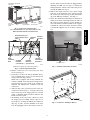
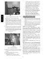
Fig. 3 -- Typical Single Point Kit Installation
UNIT SPECIFIC INSTALLATION INSTRUCTIONS
The unit-- specific installation instructions are presented in
two sections, grouped by common chassis and control box
design. Section 1 covers smaller chassis models and starts
on page 10. Section 2 covers the large chassis models and
starts on page 15. See table below for section assignment
for specific unit types and sizes.
Unit
Size
Group
AC--1
AC--2
AC--3
HP--1
DISCONNECT MOUNTING
LOCATION
HP--2
04/036
05/048
SECTION 1 UNITS
06/060
UNIT BLOCK-OFF
PANEL
07/072
INDOOR
ACCESS
PANEL
C11510
Fig. 4 -- Typical Access Panel Location
(AC--1/HP--1 04--07/036--072, HP--2 04--06 9036--060,
AC--2,3/HP--04--06/036--060)
08/090
09/102
11
12/120
14/150
MAX. TEMP/
STATIC LABEL
OUTDOOR
ACCESS PANEL
SECTION 2 UNITS
16/180
10
UNIT
BLOCK-OFF
PANEL
OUTDOOR
ACCESS PANEL
INDOOR
ACCESS
MAX. TEMP/
PANEL
STATIC LABEL
C11511
Fig. 5 -- Typical Access Panel Location
(AC--1 08--14/090--150, AC--2 07--12/072--120,AC--3 07,
HP--1 08--23/090--120, HP--2 07--09/072--102)
SINGLE POINT BOX
(NOT SHIPPED WITH
UNIT)
CENTER
POST
CRHTR,CRSIN
trol box which are not used must be plugged before
installing the SPB. Use foil tape or reinstall the
bushings from the outside of the control box prior to
securing the SPB. (See Fig. 9.)
8. Remove the single point box cover. Secure single
point box to the underside of the control box with
the 2 screws provided. (See Fig. 3.) Re-- install bushing on the SPB tap conductors. (See Fig. 9.)
9. Secure the rainshield (conduit drip boot bracket) assembly to the back of the single point box with 2 of
the screws provided. (See Fig. 3.) The channel portion of the bracket assembly extends to the top panel behind the control box. Secure all wires to bracket with field-- supplied wire tie as shown. (See Fig.
13.)
DISCONNECT MOUNTING
LOCATION
HEATER
COVERS
Seal Back Corner
Seal Bottom Corner
MAIN
CONTROL
BOX
HEATER
MOUNTING
HEATER
HEATER
BRACKET
MODULE
MODULE
(LOCATION 1) (LOCATION 2)
Foil Tape Locations
C101085
C11514
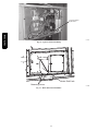
Fig. 7 -- Seal Strip and Foil Tape Locations
(All units except large [3 outdoor fan] cabinet)
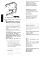
Fig. 6 -- Typical Component Location
4. Remove control box cover and center post. Save
screws. (See Fig. 6.)
5. If unit does not have the factory-- installed disconnect or HACR option or has not had field power
wiring connected, skip to Step 6.
When unit is equipped with factory-- installed disconnect or HACR or has field power wiring connected, disconnect the power leads at the control box
terminals and withdraw the conductors from the
control box.
6. Add seal strip to the rear bottom corner of the control panel as shown in Fig. 7. Foil tape open screw
holes on the back of the single point box as shown
in Fig. 7. Different single point boxes will have different screw holes open.
7. All bushings in the area of the control box where
the single point box (SPB) mounts, must be removed prior to securing the SPB to the control box.
(See Fig. 8.) Also, for units installed in the snow
belt, all unplugged holes in the bottom of the con-
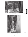
C09005
Fig. 8 -- Control Box -- Bushings to Remove
11
CRHTR,CRSIN
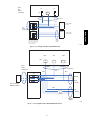
In the unit control box, relocate these wires:
At IFC terminal 13, disconnect
Compressor 1 BLU and Compressor 2
ORN leads; reconnect at TB10A.
At C1 terminal 13, disconnect ID Fan
YEL lead; reconnect at TB10B.
At C1 terminal 11, disconnect BLK jumper;
reconnect to IFC terminal 11.
Route the first set of tap conductors
(attached at upper fuse block, with
bushing per Step 5) into the main control
box; connect at:
BLK: C1 terminal 11
YEL: C1 terminal 13
BLU (long lead with terminal): TB10A
Route the second set of tap conductors
(attached at second fuse block) into the
main control box; connect at:
BLK: IFC terminal 11
YEL (long lead with terminal): TB10B
BLU: IFC terminal 13
(2.) Units requiring ONE TB10 terminal block
Locate two 42-- in (1067 mm) BLU and YEL
wires with single insulated female terminal
shipped in a bag with this kit.
C09006
Fig. 9 -- Bushings Replaced from Outside Control Box
10. Connect power tap conductors to unit main control
box.
a. Single point boxes with two or three tap conductors-- Route the tap conductors (with bushing
added per Step 5) into the unit main control box.
Connect the power tap conductors to the designated terminals in the unit’s control box for field
power connections. Refer to the wiring diagram
in the unit, to unit installation instructions for
Field Power Wiring Connections or to Appendix
A, B or C.
b. Single point boxes with six tap conductors
(CRSINGLE043A00, 045A00, 049A00, 051A00,
053A00 and 054A00)
These single point boxes include two sets of
three-- - lead power tap conductors connected to
two separate fuse blocks, at FU2 and FU3.
These kits also include two terminal blocks
(TB10A and TB10B) and attachment screws; the
TB10 block usage will be two, one or none,
based on base unit.
Refer to TB10 usage tables on page 9 to
determine quantity required for this unit.
At the single point box, locate the BLU tap
conductor on fuse block FU3 (second block);
disconnect and discard. Connect the 42-- in
BLU wire to FU3.
Mount one TB10 terminal block in the unit’s
control box between compressor contactors
C1 and C2. (See Fig. 10.)
S Relocate these wires:
At IFC terminal 13, disconnect Compressor
2 ORN and OFM BLU leads; reconnect
at TB10.
S Remove these leads:
At C1-- - 11, remove BLK jumper to C2-- - 11.
Discard.
At C1-- - 13, remove YEL jumper to C2-- - 13.
Discard.
Route the first set of tap conductors
(attached at upper fuse block, with bushing
per Step 5) into the main control box;
connect at:
BLK: C1 terminal 11
YEL: C1 terminal 13
BLU: IFC terminal 13
(1.) Units requiring TWO TB10 terminal blocks
Mount these terminal blocks in the unit’s
control box next to compressor contactor
C1. (See Fig. 10 and Appendix A or C.)
Locate two 42-- in (1067 mm) BLU and YEL
wires with single insulated female terminal
shipped in a bag with this kit.
Route the second set of tap conductors
(attached at second fuse block) into the main
control box; connect at:
BLK: C2 terminal 11
YEL: C2 terminal 13
BLU: TB10
At the single point box, locate the BLU tap
conductor on fuse block FU2 (upper block);
disconnect and discard. Connect the 42-- in
BLU wire to FU2.
At the single point box, locate the YEL tap
conductor on fuse block FU3 (second block);
disconnect and discard. Connect the 42-- in
YEL wire to FU3.
12
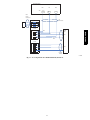
(3.) Units requiring NO TB10 terminal block
Connect both sets of tap conductors to unit
terminal block TB1; connect at:
BLK: terminal 11
YEL: terminal 12
BLU: terminal 13
Route the first set of tap conductors
(attached at upper fuse block, with bushing
per Step 5) into the main control box.
CRHTR,CRSIN
Route the second set of tap conductors
(attached at second fuse block) into the main
control box.
HEATER
012A
CIR#1
CIR#2
HEATER
017A
C101084
Fig. 10 -- TB10 Locations and Connections
13
Three-- - phase applications: Skip to Step 6.
CRHEATER101A00-- - 109A00,
CRHEATER110A-- - 119A00
CRHEATER264A00-- - 269A00
CRHEATER297A00-- - 299A00,
CRHEATER301A00
CRHEATER308A00
CRHEATER316A00-- - 322A00
1. Identify heater cover(s) to remove. See Fig. 14 and
15.
a. All two-- heater installations: Remove both
heater covers. Save covers and screws.
b. All single-- heater installations EXCEPT
CRHEATER265A00 – 269A00, 299A00,
301A00:
Remove the heater cover at Heater 1 position.
Save cover and screws.
c. Heater CRHEATER2650A-- - - - 269A00 ONLY:
Remove the heater cover at Heater 2 position.
Save cover and screws.
d. Heater CRHEATER301A00 ONLY: Remove
both heater covers. Save the screws. Discard
the covers.
2. Open the heater package(s) and remove the heater
module, heater support track (where provided),
screws, wring label, miscellaneous parts.
3. All heaters EXCEPT CRHEATER101A00-- 109A00,
265A00-- 269A00 and 301A00: Install heater slide
bracket(s) from the heater kit through the bottom of
the heater mounting hole(s) and fasten each with the
two screws provided. (See Fig. 15.)
4. Install the heater module(s) in the heater support
bracket opening(s). On two-- heater installations
where there is no key-- forced heater position, install
the heater with the higher kW rating in heater position 1.
a. Heaters CRHEATER101A00-- 109A00,
265A00-- 269A00:
To install module, insert heater frame into location notch in heater bracket opening in unit and
slide heater through the opening. Fasten heater
module to heater mounting bracket with the 4
screws saved from Step 1. (See Fig. 14.)
b. Heater CRHEATER301A00 only: To install
module, insert both heater frames into location
notches in heater bracket opening in unit and
slide heater through the opening. Fasten heater
module to heater mounting bracket with the 4
screws saved from Step 1. (See Fig. 17.)
c. All other heaters: To install module, engage
flange on heater with track in unit and slide
heater through mounting bracket opening. Fasten
heater module to heater mounting bracket with
the 4 screws saved from Step 1. (See Fig. 15.)
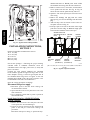
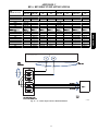
5. Single-- - phase heater conversion
208/230-- - v heaters CRHEATER101A00 through
104B00 are factory-- - wired for 3-- - phase applications but can be converted to single-- - phase by
changing one wire as described below.
For single-- - phase applications, rewire the heater as
follows (see Fig. 11):
a. Connect 10-- - gauge RED wire provided with
heater package to splice connector included in
package.
b. Remove YEL wire from heater relay HR at terminal 11.
c. Reconnect the YEL wire from step b to splice
connector on RED wire.
d. Using the wire tie provided, fasten RED wire to
heater power wire harness near existing wire tie
on heater module. This provides strain relief for
the red wire. See Fig. 12.
Connect the BLU and YEL conductors in the
heater power wire harness to same L1 pole on
single point box TB or FU fuse block. Connect
the BLK and RED conductors in the heater power wire harness to same L2 pole on single point
box TB or FU fuse block. See Fig. 11 .
Connect YEL
at splice
Disconnect
YEL
CONNECT
TO L2
CONNECT
TO L1
LEGEND
HR -- Heater Relay
HTR -- Heater
LS
-- Limit Switch
C13448
Fig. 11 -- Single--Phase Heater Wiring
Wire Tie
RED WIRE
HEATER
POWER
WIRE
HARNESS
21
23
11
13
CRHTR,CRSIN
Installing Electric Heater
MODEL NO.
OD
ERIAL NO.
SPLICE
CONNECTOR
22.2
ISTED AIR
NDITIONING
UIP ACCESS
346N.
P/N
23
2-
1
3
5610-4
REV
C13449
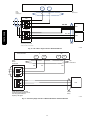
Fig. 12 -- Typical Single--Phase Wiring Installed
14
6. Route power wires from heater module(s) through
the foam bushing in the center partition and into the
single point box. (See Fig. 3.) Connect to terminal
block or fuse blocks per schematics in Appendix A
or B. See Tables at beginning of each Appendix to
identify the appropriate figure.
KEY FOR MODULE LOCATON 1
If no single point box is required for the unit and
heater combination, run the heater power supply
wiring through the grommet holes to the main unit
control box’s field power connection points or to
optional factory-- supplied disconnect.
C09010
Fig. 14 -- Typical Electric Heat Installation
(AC--1 Sizes 04 to 07 and 036 to 072, AC--2 Sizes 04--06,
HP--1 Sizes 04--07 and 036 to 072, HP--2 Sizes 04--06)
7. Factory control wiring for heaters runs from unit
control box to terminal block TB-- 4, mounted in the
heater compartment above module 1 location. (See
Fig. 6 and 18.) Connect the heater control wiring at
TB-- 4.
BD236B
N—TRAN 3O—BV2075
E 60 HZ 30-8703
30V—OR 200V—RD OV—YL
D 24V
75VA
C—COMM
HEATER
SLIDE
TRACK
FLANGE
TRACK SCREWS
KEY FOR MODULE LOCATION 1
C10557
Fig. 15 -- Typical Module Installation
(AC--1 Sizes 08 to 14 and 090 to 150, AC--2 Sizes 07--12,
HP--1 Sizes 08--12 and 090 to 121, HP--2 Sizes 07--09)
CONDUIT
CONDUIT
DRIP BOOT
WIRE TIE
C08417
Fig. 13 -- Typical Conduit Installation
15
CRHTR,CRSIN
All heaters are single bank heaters except
CRHEATER111A00, 112A00, 268A00, 269A00,
301A00, 318A00 and 321A00 which are dual bank
heaters. These heaters will be wired as two heaters
(i.e., 6 leads). Fusing is shown pictorially on the
unit wiring schematic label.
CRHTR,CRSIN
C11513
Fig. 16 -- Heater Bracket Keyway
(AC--2, HP--2 Size 07 and 14 Units Only)
C13447
Fig. 17 -- Installing CRHEATER301A00
16
LCTB
DEFROST
BOARD
CONTL
BOARD
VIO
3
ORN
12
BRN
TB4
ORN
VIO
BRN
1
2
3
E-HEAT
ORN
P3-3
BRN
TB4
ORN
BRN
1
3
VIO
VIO
VIO
BRN
Field
Connections
BRN
Elec Htr
VIO
HR2
BRN BRN
VIO
Field
Connections
Elec Htr
VIO HR2
BRN
HR1
BRN
BRN
VIO
VIO
HR1
BRN
HR1: On Heater 1 in Position #1
HR2: On Heater 2 in Position #2 (if installed)
HR1: On Heater 1 in Position #1
HR2: On Heater 2 in Position #2 (if installed)
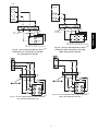
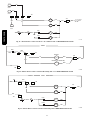
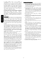
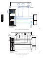
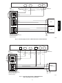
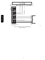
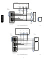
Fig. 18 - Accessory Electric Heater Control
Connections (AC-- 1 Except Size 16 and 180,
AC-- 2 Except Size 14 and 150)
Fig. 20 - Accessory Electric Heater Control
Connections (HP-- 1 Except Size 14 and 150,
HP-- 2 Except Size 12 and 120)
C08331
C09013
C11554
Fig. 21 -- Accessory Electric Heater Control Connections
(HP--2, Size 06 and 060, 575V only)
C11555
Fig. 19 -- Accessory Electric Heater Control Connections
(AC--2, Size 06 and 060, 575V only)
17
CRHTR,CRSIN
2
3.
4.
5.
6.
21
23
11
13
7.
MODEL NO.
OD
CRHTR,CRSIN
ERIAL NO.
ISTED AIR
NDITIONING
UIP ACCESS
346N.
23
P/N
2-
1
3
5610-4
installed disconnect or HACR power leads at TB1
and withdraw the wiring from the unit control box.
Remove outdoor access, control box, and left indoor
access panels from the unit. See Fig. 23. Fig. 24
shows the unit with the panels already removed.
Optional – The center post may be removed to facilitate wiring.
Remove the bushings and plug from the control
panel per Fig. 25. Save the bushings and discard the
plug.
Add seal strip to the rear bottom corner of the control panel as shown in Fig. 26.
Foil tape open screw holes on the back of the single
point box as shown in Fig. 26. Different single point
boxes will have different screw holes open.
SINGLE POINT BOX
(NOT SHIPPED WITH
UNIT)
REV
CENTER
POST
HEATER
COVERS
C08137
Fig. 22 -- Typical 3--Phase Wiring Installed
INSTALLATION INSTRUCTIONS,
SECTION 2
Product Groups/Sizes included in this section:
AC-- 1 16 (180)
AC-- 2 14 (150)
AC-- 3 08-- 12
HP-- 1 14 (150)
HP-- 2 12 (120)
Check sales packages – Following the project drawing
schedule tables or submittal documents, select the
scheduled heaters and single point boxes (if used) and
place at each unit.
Compare the sales package number(s) for scheduled
heater modules against the approved usage table on the
unit’s infoplate. See Fig. 1 and 2 for typical plate data. If
the scheduled heater usage does not appear on the unit
infoplate label, STOP. Contact the project engineer or the
local distributor sales office for clarification.
Open the cartons and inspect for damage.
MAIN
CONTROL HEATER
BOX
MODULE
(LOCATION 1)
HEATER
MODULE
(LOCATION 2)
HEATER
MOUNTING
BRACKET
C11515
(AC--1 16/180, AC--2 14--150, AC--3 08--12, HP1 14/150, HP--2
12/120)
Fig. 23 -- Typical component Location
Disconnect field power supply
1. Disconnect power to the unit. Lock-- - out/tag-- - out
on unit disconnect switch.
2. Open and remove the access panel and cover to the
main control box.
3. Use a voltmeter to check that no power is present at
unit terminal block.
Install Single Point Box (CRSINGLE047A00,
050A00----054A00)
1. Remove kits from boxes and verify that all of the
correct parts have arrived undamaged.
2. If power is already connected to unit, disconnect all
power to the unit per correct lock-- - out/tag-- - out
procedures.
Disconnect field power wiring or optional factory-18
Control Box
Access
Panel
Outdoor
Access
Panel
Heater Covers
C10170
Fig. 24 -- Typical Unit with Access Panels Removed
Plug Location
Bushings
(Re-installed)
Single Point Box Mounting Screws
C10169
Fig. 25 -- Single Point Box Installation Details
19
CRHTR,CRSIN
Left
Indoor
Access
Panel
conductors (pigtails) from the single point box to
the unit’s power terminal block TB-- 1 per unit
label wiring schematic and per Appendix A or B
and connection figures. A representative installation of two 480V heaters and corresponding
single point box is shown in Fig. 28, 29, and 30.
b. CRSINGLE051A00, 053A00 and 054A00
These kits include two sets of tap conductors
(blue, yellow and black pigtails) connected at
fuse blocks 1 and 2. Connect these leads in parallel to the unit’s power terminal block TB-- 1 per
the unit label wiring schematic and per Appendix A, B or C and connection figures.
(These kits also include two small terminal
blocks (TB10). The TB10 blocks are not used
with large cabinet units in this section; discard.)
Seal Back Corner
CRHTR,CRSIN
Seal Bottom Corner
Foil Tape Locations
C101085
Fig. 26 -- Seal Strip and Foil Tape Locations
8. Remove the cover from the single point box.
9. Install the single point box under the control panel
with two screws down through the control panel
(Fig. 25) and one screw (not shown) into the center
post. (See Fig. 25.) Holes have been provided.
Foam wire guides in the center post may have to be
removed. If center post was removed per step 4, the
single point box will have to be screwed into it
later.
10. The single point box kit will contain two rain shield
brackets, a larger bracket with boot seal and a smaller (shorter) bracket without a seal. Remove the
seal from the larger bracket and push the conduit
drip boot seal into the short rain shield bracket. (See
Fig. 27.) Discard the larger bracket.
Conduit Drip Boot
Rain Shield Bracket
C10167
Fig. 27 -- Rain Shield Installation
11. Install the rain shield bracket to the left and behind
the single point box using the two screws and holes
provided.
12. Re-- install the bushings removed in Step 5.
13. Connect the tap conductors.
a. CRSINGLE047A00, 050A00 and 052A00
Connect the blue, yellow, and black power tap
Install CRHEATER288A00--296A00
1. Remove and save the heater covers.
2. Install heater slide track(s) from the heater kit
through the bottom of the heater mounting hole(s)
and fasten each with the two screws provided. (See
Fig. 31.)
3. Install the heater(s) (Fig. 32, 230V shown) into their
mounting location(s) using the screws provided.
Tables 2 and 3 give the correct heater location as a
function of heater size, voltage, and supply air flow
direction and unit supply air opening size
NOTE 1: Heaters with Restrictor Plates
Heater part numbers CRHEATER288A00, 289A00,
290A00, 294A00, 295A00 and 296A00 have a Restrictor
Plate attached to the heater base plate (see Fig. 33). The
horizontal projection of this plate engages a slot on the
lower left-- hand side of Heater Position 2 (right-- hand
opening), thus permitting a heater mounting in the
right-- hand heater opening and preventing its inadvertent
mounting in the left-- hand heater opening.
On certain heater applications in Tables 2 and 3,
designated by dagger ({) symbol, a heater with a
Restrictor Plate must be installed in the left-- hand heater
opening. On these installations ONLY, remove the two
screws at the Restrictor Plate, remove the plate and
discard the plate and screws. Apply foil tape over the
open screw holes.
NOTE 2: Heater CRHEATER295A00, Vertical Unit,
Table 3.
The mounting location for heater CRHEATER295A00
differs based on unit type. When this heater is installed in
a unit type AC-- 1, AC-- 2 or AC-- 3 with vertical supply
duct (unit base opening size is approximately 36 x 28
inches), the heater is located in Heater Position 2
(right-- hand opening), with Restrictor Plate intact.
When this heater is installed in a unit type HP-- 1 or HP-- 2
with vertical supply duct (unit base opening size is
approximately 30 x 16 inches), the heater is located in
Heater Position 1 (left-- hand opening) and Restrictor Plate
must be removed. On these installations ONLY, remove
the two screws at the Restrictor Plate, remove the plate
and discard the plate and screws. Apply foil tape over the
open screw holes.
20
CRHTR,CRSIN
C10174
Fig. 28 -- Heater Wiring
C10172
Fig. 29 -- Typical Single Point Box Wiring
21
CRHTR,CRSIN
Single Point Box
Power Wires
C10175
Fig. 30 -- Typical Control Panel Wiring
Heater Slide Track
Mounting Screws
C10198
Fig. 31 -- Heater Slide Track Installation
22
Heater Mount Locations
Single Element
Heater Module
C10168
Fig. 32 -- Typical Heaters
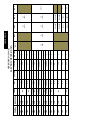
Table 3 – Heater Location for Vertical
Return and Discharge*
Table 2 – Heater Location for Horizontal
Return and Discharge*
Heater
Heater Slot Location
Heater
kW
Volts
Left
Right
CRHEATERXXXX00
288A
10.0
240
--
288A
291A
16.5
240
291A
--
288A + 291A
26.5
240
291A
294A
33.5
240
288A + 294A
43.5
240
291A + 294A
50.0
240
294A + 294A
67.0
240
289A
10.0
292A
16.5
289A + 292A
Heater Slot Location
kW
Volts
Left
Right
288A
10.0
240
--
288A
291A
16.5
240
291A
--
288A
288A + 291A
26.5
240
291A
288A
--
294A
294A
33.5
240
--
294A
288A{
294A
288A + 294A
43.5
240
288A{
294A
291A
294A
291A + 294A
50.0
240
291A
294A
294A{
294A
294A + 294A
67.0
240
294A{
294A
480
--
289A
289A
10.0
480
--
289A
480
292A
--
292A
16.5
480
292A
--
26.5
480
292A
289A
289A + 292A
26.5
480
292A
295A
33.5
480
--
295A
289A + 295A
43.5
480
289A{
295A
33.5
480
292A + 295A
50.0
480
292A
295A
295A
(See Note 2, Page
20)
295A {
(HP---1
HP---2 only)
289A
295A
(AC ---1,
AC ---2,
AC ---3 only)
295A + 295A
67.0
480
295A{
295A
289A + 295A
43.5
480
289A{
295A
292A + 295A
50.0
480
292A
295A
295A + 295A
67.0
480
295A{
295A
290A
CRHEATERXXXX00
290A
10.0
600
--
290A
293A
16.5
600
293A
--
290A + 293A
26.5
600
293A
290A
290A
10.0
600
--
296A
33.5
600
--
296A
293A
16.5
600
293A
--
290A + 296A
43.5
600
290A{
296A
290A + 293A
26.5
600
293A
290A
293A + 296A
50.0
600
293A
296A
296A
33.5
600
--
296A
290A + 296A
43.5
600
290A{
296A
293A + 296A
50.0
600
293A
296A
296A + 296A
67.0
600
296A{
296A
* XXXX --- 4 digit heater in table. For example, a CRHEATER291A000 is
listed as a 291A.
{Remove Restrictor Plate to install in Left Slot Location. Use foil tape to
cover holes.
296A + 296A
67.0
600
296A{
296A
* XXXX --- 4 digit heater in table. For example, a CRHEATER291A000 is
listed as a 291A.
{ Remove Restrictor Plate to install in Left Slot Location. Use foil tape to
cover holes.
23
CRHTR,CRSIN
Dual Element
Heater Module
CRHTR,CRSIN
C13466
Fig. 33 -- Restrictor Plate
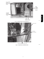
4. Connect the heater control wiring to terminal block
TB4 (located to left of the heaters, see Fig. 43 and
44.)
TB4 has five terminals. (See Fig. 34 and 36.) Bottom row left terminal is “R Use”; it has a factory
RED connection. Bottom row right terminal is “C
Use”; it has a factory BRN connection. For AC
units, top row left is designated as “W1 Use” ad has
factory ORN connections. The top row center is
designated as “W2 Use” and has factory VIO connections. For HP units, top row left and center terminals are designated “W2 Use” and have factory
ORN connections. The fifth terminal is for field-option connection of a staging control.
has 4 control wires, connect both the ORN and VIO
control wires from the heater to ORN on TB4 for 1st
stage heating and connect the ORN and VIO control
wires from the other heater to VIO on TB4 for 2nd
stage heating. (See Fig. 39.)
For AC units with one of these heater packages that
has these 4 control wires plus a heater package that
has 3 control wires, connect both the ORN and VIO
control wires from the 4 control wire heater to ORN
on TB4 for 1st stage heating and connect the ORN
control wire from the other heater with 3 control
wires to VIO on TB4 for 2nd stage heating.
For HP units, connect ORN and VIO wires to TB4’s
“W2 Use” terminals.(See Fig. 42.)
CB
CRHEATER288A00-- 293A00 Heaters
These heaters have two control wires: ORN for
heater contactor and BRN for control common.
Connect BRN wire(s) to TB4’s “C Use” terminal.
(Second BRN wire will require use of the piggyback
terminal on the factory BRN wire.) For AC units,
connect heater ORN control wiring to ORN on TB4
for 1st stage heating and for units with heater packages, connect to VIO on TB4 for 2nd stage heating.
(See Fig. 38.) For HP units, connect heater ORN
control wires(s) to an available terminal on TB4’s
“W2 Use” group. (See Fig. 40.)
24V
3.2 AMPS
TRAN1 FROM POWER SCHEMATIC
24V
GRN/
YEL
BRN
BRN
24V
RED
5
TRAN2 FROM POWER SCHEMATIC
CB
24V
3.2 AMPS
RED
BRN
GRN/
YEL
ORN
1 EHR 0
BRN
VIO
1 OFR 0
BRN
3
BRN
24V
BRN
24V
EHR
RED
8
6
ORN
ORN
NOTE 4
AND 6
RED
BLK
TB4
ELECTRIC
BRN
HEAT(ACCESSORY)
SEE HEATER LABEL DIAGRAM
FPT
BLK
BRN
BRN
C10561
Fig. 34 -- TB4 Wiring (HP Only)
CRHEATER294A00-- 296A00 Heaters
These heaters have four control wires: ORN and
VIO for heater contactors, RED for safety circuit
power and BRN for control common. Connect RED
wire to TB4’s “R Use”. Connect BRN wire to
TB4’s “C Use” terminal. For AC units with one
heater package that has these 4 control wires, connect heater ORN control wiring to ORN on TB4 for
1st stage heating and to VIO on TB4 for 2nd stage
heating.
For AC units with 2 of these heater packages that
C11127
Fig. 35 -- TB4 Wiring (AC Only)
24
Table 4 – Optional Factory Installed Disconnect Amp Ratings
Optional Outdoor Temperature Control
at One Heater Stage –
Move heater wire to this terminal and
connect outdoor temperature switch
between 2nd and 3rd terminals.
Unit
Group
Unit
Sizes
04-07
AC-1
16
C Use
R Use
C10604
04-06
Fig. 36 -- TB4 Terminal Use (HP Only)
AC-2
NOTE:
8
CONTROL
BOARD
W1 Use
08-14
Optional Outdoor Temperature Control
at One Heater Stage –
Move heater wire to this terminal and
connect outdoor temperature switch
between 2nd and 3rd terminals.
W2 Use
07-12
14
VIO
VIO
04-06
AC-3
12
C Use
R Use
07-09
12
CONTROL
BOARD
04-07
C11129
Fig. 37 -- TB4 Terminal Use (AC Only)
HP-1
08-12
14
04-06
HP-2
08-09
12
Disconnect
Size Amps
80
60
Volts
208/230
460, 575
208/230
460, 575
208/230
460, 575
208/230
460, 575
208/230
460, 575
208/230
460, 575
208/230
460, 575
208/230
460, 575
208/230
460, 575
208/230
460, 575
208/230
460, 575
208/230
460, 575
208/230
460, 575
208/230
460, 575
208/230
460, 575
80
115 #
100
80
60
80
115 #
100
CRHTR,CRSIN
NOTE:
W2 Use
80
80
115 #
100
80
60
80
115 #
100
80
80
115 #
100
1 ---Standard Efficiency
2 --- High Efficiency
3 --- Ultra High Efficiency
#115 ---A is Application Limit based on factory wire size.
CONTROL
BOARD
2
CONTROL
BOARD
3
VIO
ORN
TB4
CONTROL
BOARD
8
HEATER 1
U
RED
ORN
LS1
TB4
LS2
ORN
ORN
HC1
BRN
BRN
ORN
12
CONTROL
BOARD
*HEATER 2 (IF INSTALLED)
ORN
LS1
LS2
ORN
ORN
HC1
BRN
* 2 stage heat shown. Connect orange wire from
Heater 2 HC1 to orange on TB4 for 1 stage heat.
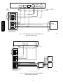
C11134
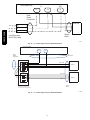
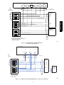
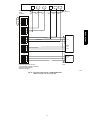
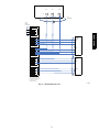
Fig. 38 -- Electric Heater Control Connections -- Air Conditioner with 1 or 2 CRHEATER288A00--293A00
25
12
VIO
CONTROL
BOARD
3
ORN
CONTROL
BOARD
TB4
TB4
ORN
U
RED
HCR1
BRN
HCR2
BRN
HC1
BRN
HC2
BRN
VIO
8
BRN
12
BRN
CONTROL
BOARD
CONTROL
BOARD
HCR1
LS2
CRHTR,CRSIN
LS1
RED
RED
RED
HCR2
C11135
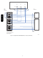
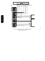
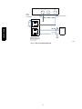
Fig. 39 -- Electric Heater Control Connections -- Air Conditioner with 1 CRHEATER294A00--296A00
TRAN2
EHR
RED
ORN
ORN
TB4
HEATER 1
TB4
ORN
TS
BRN
HC1
BRN
ORN
HEATER 2 (IF INSTALLED)
BRN
HC1
TS
RED
TB4
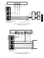
C13468
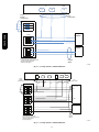
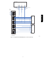
Fig. 40 -- Electric Heater Control Connections--Heat Pump with 1 or 2 CRHEATER288A00--293A00
TRAN2
RED
EHR
RED
BRN
ORN
TB4
ORN
TB4
ORN
HCR1
BRN
HCR2
BRN
HC1
BRN
HC2
BRN
VIO
BRN
BRN
RED
TB4
RED
LS1
HCR1
LS2
RED
HCR2
C13469
Fig. 41 -- Electric Heater Control Connections--Heat Pump with 1 CRHEATER294A00--296A00
26
TRAN2
RED
EHR
RED
BRN
ORN
ORN
TB4
1-STG HEATER
ORN
VIO
LS
HC1
ORN
BRN
2-STG HEATER
TB4
HCR1
BRN
HCR2
BRN
BRN
BRN
RED
RED LS1
LS2
HCR1
RED
HC1
BRN
HC2
BRN
HCR2
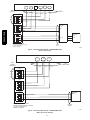
C13470
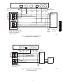
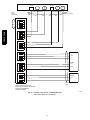
Fig. 42 -- Electric Heater Control Connections--Heat Pump with 1 CRHEATER288A00--293A00
Plus 1 CRHEATER294A00--296A00 (2--Stage Heater)
Terminal Block 4
(TB4)
Heater Cover
C10173
Fig. 43 -- Heater Wiring
27
CRHTR,CRSIN
2-Stage Heater
TB4
Heater Covers
CRHTR,CRSIN
Terminal Block 4
(TB4)
C10171
Fig. 44 -- Heater Wiring and Covers
C11512
Fig. 45 -- Max. Air Temp/Max. Ext. Static
28
NOTE: Installers of unit power supply wiring connecting
to these air conditioning and heat pump units must be
familiar with applicable requirements of the National
Electrical Code (NFPA Standard 70), Articles 440, 430
and 424 dealing with multiple load systems incorporating
refrigeration compressors, motors and electric heating
equipment. Installers must also be familiar with and
observe all local codes regarding unit power supply
wiring.
In most instances, adding electric heaters to these units
will result in an increase in unit power supply wire size
compared to base unit electrical loads. These changes may
also impact the size selection of the branch circuit
overload protection device and the unit safety disconnect
switch. Check the unit’s informative data label (see Fig.
1 and 2 for examples) for minimum wiring sizing
ampacity for full combined load (including power exhaust
if also installed), for branch circuit protection size (a
maximum value) and for unit minimum disconnect switch
size.
Device
Power Supply Wire
Branch Circuit Protection
Disconnect Switch
Infoplate Designation
MIN CKT AMPS
FUSE OR HACR
BREAKER
MINIMUM UNIT DISCONNECT
All wiring that terminates at a unit-mounted terminal must
be selected from wiring materials under the NEC Table
310.15(B)(16), 75 C (or higher) column only. Check
specifications for external disconnect lug sizes to
determine if 60 C wiring materials may be used between
branch circuit origin and the disconnect switch.
There are four different situations that an installer can
encounter with these units. Three are for new unit
installations (base unit has not been connected to a power
supply already): Unit without factory disconnect switch,
unit with factory disconnect switch and unit with factory
HACR breaker. The fourth situation is for an existing unit
already connected to a power supply and the heaters are
being retrofitted. For each situation, there is usually a
without single point box and a with single point box
condition. Each situation is discussed below.
New Unit Without Factory Disconnect or HACR
Installation WITHOUT Single Point Box: Unit power
supply wires from the external (field-supplied) disconnect
switch are connected to the base unit’s power connection
terminal lugs. Refer to unit wiring label to identify these
terminals (these may be lugs on contactors or at power
terminal block).
The heater power wires are also
connected at these terminals.
Installation WITH Single Point Box:
Remove knockouts for appropriate size conduit
from unit block-- - off panel and single point box. Install
conduit (rigid or electrometallic tubing)
through conduit drip boot as shown. (See Fig. 13.)
Drip boot will accept conduit sizes 3/4-- - in. to 1-- - 1/2
inches. The drip boot eliminates the need for watertight
conduit fittings at the single point box.
Unit power supply wires from the external (field-supplied)
disconnect switch are connected to the power lugs on the
field connection device provided in the Single Point Box.
This device may be a terminal block or fuse block FU2’s
line side terminals. The heater power wires are connected
to the load side terminals on the same device.
New Unit With Factory Disconnect
The optional factory-- - supplied disconnect has a
maximum rating per Table 4.
Check this unit’s infodata plate for the MINIMUM
DISCONNECT SWITCH value (see Fig. 1 and 2) and
compare to the Table 4 value.
If required minimum disconnect value is LOWER than
rating in Table 4: Reconnect the factory wiring from the
factory disconnect at the Single Point Box’s terminal
block or fuse block FU2’s line side terminals (or to main
control box’s line connection lugs if no Single Point Box
is installed). Remove any factory test leads connected at
disconnect line side terminals; discard these wires.
Connect unit power supply wires to disconnect switch line
side lugs.
If required minimum disconnect value is HIGHER than
rating in Table 4:
For unit with 60-- A, 80-- A or 100-- A disconnect, remove
the factory disconnect switch assembly and wiring. Install
a field-- supplied disconnect switch sized per unit marking.
Complete connections per instructions above under “New
Unit Without Factory Disconnect or HACR.”
For unit with 115-- A disconnect AND required minimum
disconnect value per unit infodata plate is less than
200-- A: Remove the factory wires at load side terminals
of the disconnect switch. Size new wires based on unit
MIN CKT AMPS value for unit plus heaters plus power
exhaust (if installed). Connect new wires at disconnect
switch load side terminals and to Single Point Box’s
terminal block or fuse block FU2’s line side terminals.
Remove any factory test leads connected at disconnect
line side terminals; discard these wires. Connect unit
power supply wires to disconnect switch line side lugs.
For unit with 115-- A disconnect AND required minimum
disconnect value per unit infodata plate is GREATER than
200-- A: Remove the factory disconnect switch assembly
and wiring. Install a field-- supplied disconnect switch
sized per unit marking. Complete connections per
instructions above under “New Unit Without Factory
Disconnect or HACR.”
New Unit With Factory HACR
The amp rating of the HACR factory installed option is
based on the size, voltage, indoor motor and other
electrical options of the unit as shipped from the factory.
When field installed accessory electric heaters are added
to the unit, the HACR may no longer be of the proper amp
rating and therefore will need to be removed from the
unit.
Check this unit’s infodata plate for the FUSE OR HACR
BREAKER value (see Fig. 1 and 2) and compare to the
factory HACR breaker rating value.
29
CRHTR,CRSIN
UNIT POWER SUPPLY WIRING –
ALL UNITS
CRHTR,CRSIN
If marked HACR value on unit dataplate is
UNCHANGED from rating unit-- mounted HACR:
Reconnect the factory wiring from the factory HACR at
the Single Point Box’s terminal block or fuse block FU2’s
line side terminals (or to main control box’s line
connection lugs if no Single Point Box is installed).
Remove any factory test leads connected at HACR line
side terminals; discard these wires. Connect unit power
supply wires to HACR line side lugs.
If marked HACR value on unit dataplate is GREATER
than rating on unit-- mounted HACR: Remove the factory
HACR switch assembly and wiring.
Install a
field-- supplied fused or HACR disconnect switch sized per
unit marking. Complete connections per instructions
above under “New Unit Without Factory Disconnect or
HACR.”
Complete Unit Installation
1. Mark the appropriate block on the unit nameplate
for the accessory heater kW installed. Note the required MIN CKT AMPS value for this unit-- - heater
combination. Ensure the field power conductors are
sized to handle this ampacity.
2. Locate the heater covers. For all heaters except
CRHEATER301A00, the heater cover is the plate
removed from the heater mounting bracket in Step 4
page 11 or Step 3 page 18. For CRHEATER301A00
only, a new, wider cover is included in the accessory
heater package. See Fig. 17.
3. Place adhesive-- - backed wiring label on flanged
side of heater cover.
4. Fasten heater cover to heater module with 2 screws
provided with heater. Flanges of cover must face
out. (See Fig. 44)
5. Set manual reset limit switch (on supply fan housing) by depressing button located between the terminals on the switch. (See Fig. 3.)
6. Close single point box cover and secure with one
screw.
7. Replace control box cover, using remainder of
screws saved from page 11, Step 4 or page 18, Step
3 of Installing Single Point Box sections.
8. Run conduit through (rigid or EMT) the conduit
drip boot in the rain shield bracket to the single
point box. Provide an appropriate fitting to connect
the conduit to the single point box wall and ground
appropriately. (See Fig. 28.) Drip boot eliminates
the need for watertight conduit fittings at the single
point box.
9. Run wire through conduit connecting outside power
to the designated terminals at the top of the single
point box. Ground appropriately. (See Fig. 30.)
10. Replace indoor and outdoor panels with screws
saved from Step 2 of Installing Single Point Box
section on page 8. Place adhesive-- - backed Max.
Air/ Max. Static label on external panel that covers
heaters. (See Fig. 4, 5, and 45.)
11. If all other work on the unit is done, reapply unit
power per lock-- - out/tag out procedures.
Existing Unit
An existing unit will usually have been installed following
the values marked on the base unit’s informative data
plate for wire sizing, branch circuit over-current
protection and disconnect switch rating. When electric
heaters are added to air conditioning (cooling) units, these
values may be changed; when electric heaters are added to
heat pump units, one or more of these values will be
changed.
Check the installed unit’s field power wires for conductor
size and determine conductor rated ampacity per NEC
Table 310.15(B)(16). Compare this value to the MIN
CKT AMPS value on the unit infoplate for base unit plus
electric heaters (plus power exhaust if connected). If the
MIN CKT AMPS value is greater than the rated ampacity
of the power supply wires, the unit power supply
conductors must be replaced.
NOTE: Supply wiring must comply with NEC (National
Electrical Code) and all local requirements.
Check the installed unit’s branch circuit over-current
protection device (fuse or HACR breaker) for rating in
amps. Compare this value to the FUSE OR HACR
BREAKER value on the unit infoplate for base unit plus
electric heaters (plus power exhaust if connected). If the
FUSE OR HACR BREAKER value is greater than the
rated ampacity of the installed device, the unit branch
circuit over-current protection device must be replaced.
Check the installed unit’s disconnect switch for rating in
amps.
Compare this value to MINIMUM UNIT
DISCONNECT value on the unit infoplate for base unit
plus electric heaters (plus power exhaust if connected). If
the MINIMUM UNIT DISCONNECT value is greater
than the rated ampacity of the installed disconnect switch,
the unit disconnect switch must be replaced.
To complete the unit power wiring at the Single Point Box
or base unit terminals, follow the appropriate directions
under ”New Unit” discussions above.
30
APPENDIX A
AC--1, AC--2 COOLING APPLICATIONS
04---07
036---072
037
040
Fig. 46
Fig. 47
NONE
037
038
042
043
044
045
047
049
050
051
053
Fig. 48
Fig. 49
Fig. 50
AC ---1 Units
08
09---12
090---091
102---121
14
150
16
180
04---06
036---060
1--- Phase (See page 14 for conversion instructions)
Fig. 46
Fig. 47
3--- Phase
Fig. 48
Fig. 48
Fig. 49
Fig. 50
Fig. 49
Fig. 51
Fig. 52
Fig. 53
Fig. 49
Fig. 49 Fig. 49
Fig. 54
Fig. 55 Fig. 59
Fig. 56
Fig. 56 Fig. 56
Fig. 57
Fig. 58 Fig. 60
Fig. 61
31
07
072
AC ---2 Units
08---09
090---102
11---12
120
14
150
Fig. 48
Fig. 49
Fig. 51
Fig. 49
Fig. 54
Fig. 56
Fig. 57
Fig. 57
Fig. 49
Fig. 54
Fig. 56
Fig. 57
Fig. 57
Fig. 49
Fig. 59
Fig. 56
Fig. 60
Fig.61
CRHTR,CRSIN
SPB
CRSINGLEnnnA00
Unit Control Box
C
11
IFC
13
13
Field
Power
Conductors
CRHTR,CRSIN
HEATER
Heater
Wires
Unit Disconnect
MOCP 60-A Max
C13477
Fig. 46 -- AC 1--Phase Single Point Box CRSINGLE037A00
Unit Control Box
C
11
Field
Power
Conductors
BLK
11
23 11
Tap
Conductors
YEL
FU2
BLK + RED
HTR 1
BLU + YEL
FU3
BLK + RED
HTR 2
BLU + YEL
Heater
Wires
Factory wiring connects line-side
of FU2 to line-side terminals on FU3.
C13478
Fig. 47 -- AC 1--Phase Single Point Box CRSINGLE040A00
32
Unit Control Box
AC-1 SIZE 16 (180)
AC-2 SIZE 14 (150)
HP-1 SIZE 14 (150)
HP-2 SIZE 12 (120)
BLK
BLK
TB-1 11
YEL
BL U
BLU
12
13
BLU
IFTB
AC-1, AC-2
HP-1, HP-2
ALL EXCEPT ABOVE
C
IFC
11
13 11
11
Field
Power
Conductors
WITH VFD
BLK
13
11
YEL
WITHOUT
VFD
CRHTR,CRSIN
Unit Control Box
BLU
HEATER
Unit Disconnect
MOCP 60-A Max
Heater
Wires
C13479
Fig. 48 -- AC, HP — No Single Point Box
33
Unit Control Box
AC-1 SIZE 16 (180)
AC-2 SIZE 14 (150)
HP-1 SIZE 14 (150)
HP-2 SIZE 12 (120)
BLK
BLK
TB-1 11
YEL
BLU
BLU
12
13
BLU
Unit Control Box
IFTB
AC-1, AC-2
HP-1, HP-2
ALL EXCEPT ABOVE
C
CRHTR,CRSIN
11
WITH VFD
IFC
11
13 11
Field
Power
Conductors
13
11
WITHOUT
VFD
Tap
Conductors
TB
HEATER
Unit Disconnect
MOCP 60-A Max
Heater
Wires
SPB
037A
042A
047A
C13480
Fig. 49 -- AC Single Point Box CRSINGLE037A00, 042A00, and 047A00
34
Unit Control Box
Field Tap
Power Conductors
C
11
IFC
13
13
!!"5"5
Field
Power Conductors
Tap Conductors
FU2
HEATER
Heater 104 #2
if used
FU3
HEATER
Heater
Wires
Factory wiring connects line-side
of FU2 to line-side terminals on FU3.
This wiring not illustrated for
simplicity in this figure.
C10486
Fig. 50 -- AC Single Point Box CRSINGLE038A00
Unit Control Box
TB-10A
C
11
TB-10B
IFC
11
13
13
FIELD
POWER
CONDUCTOR
TAP
CONDUCTORS
FU2
BLU
BLK
YEL
YEL
BLK
BLU
HEATER
111A or 112A
CIR 1
FU3
CIR 2
Factory wiring connects line-side
of FU2 to line-side terminals on FU3.
This wiring not illustrated for
simplicity in this figure.
HEATER
WIRES
ALT.
TWO HEATER
MODULES
C10489
Fig. 51 -- AC Single Point Box CRSINGLE043A00
35
CRHTR,CRSIN
Heater 104 #1
or Heater 105
Unit Control Box
C
IFC
11
13
13
Field
Power
Conductors
Tap
Conductors
TB
CRHTR,CRSIN
FU2
HEATER
FU3
HEATER
Factory wiring connects line-side
of FU2 to line-side terminals on FU3.
This wiring not illustrated for
simplicity in this figure.
Heater
Wires
C10490
Fig. 52 -- AC Single Point Box CRSINGLE044A00
Unit Control Box
C
TB-10A
11
IFC
TB-10B
11
13
13
FIELD
POWER
CONDUCTOR
TAP
CONDUCTORS
FU2
BLU
BLK
YEL
YEL
BLK
BLU
HEATER
111A or 112A
CIR 1
FU3
CIR 2
FU4
HEATER
Factory wiring connects line-side
of FU2 to line-side terminals on FU3-FU4.
This wiring not illustrated for
simplicity in this figure.
HEATER
WIRES
C10491
Fig. 53 -- AC Single Point Box CRSINGLE045A00
36
Unit Control Box
TB-10A
C
TB-10B
11
IFC
11
13
13
FIELD
POWER
CONDUCTOR
TAP
CONDUCTORS
BLU
FU2
BLK
YEL
YEL
BLK
BLU
HEATER
111A or 112A
CIR 1
CIR 2
Factory wiring connects line-side
of FU2 to line-side terminals on FU3.
This wiring not illustrated for
simplicity in this figure.
HEATER
WIRES
ALT.
TWO HEATER
MODULES
C10489
Fig. 54 -- AC Single Point Box CRSINGLE049A00
(Except Size 14--16 and 150--180)
Unit Control Box
C2
11
C1 $$&:&:
TB-10
13
11
13
IFC
13
FIELD
POWER
CONDUCTOR
FU2
TAP
CONDUCTORS
BLU
BLK
YEL
YEL
BLK
BLU
HEATER
112A
CIR 1
FU3
HEATER
117A or 110A
CIR 2
Factory wiring connects line-side
of FU2 to line-side terminals on FU3.
This wiring not illustrated for
simplicity in this figure.
HEATER
WIRES
C10566
Fig. 55 -- AC Single Point Box CRSINGLE049A00
(AC Sizes 14 and 150 Only)
37
CRHTR,CRSIN
FU3
Unit Control Box
C
IFC
11
13
13
Field
Power
Conductors
Tap
Conductors
TB
CRHTR,CRSIN
FU2
HEATER
FU3
HEATER
Factory wiring connects line-side
of FU2 to line-side terminals on FU3.
This wiring not illustrated for
simplicity in this figure.
Heater
Wires
C10490
Fig. 56 -- AC Single Point Box CRSINGLE050A00
Unit Control Box
C
TB-10A
11
IFC
TB-10B
11
13
13
FIELD
POWER
CONDUCTOR
TAP
CONDUCTORS
FU2
BLU
BLK
YEL
YEL
BLK
BLU
HEATER
111A or 112A
CIR 1
FU3
CIR 2
FU4
HEATER
Factory wiring connects line-side
of FU2 to line-side terminals on FU3-FU4.
This wiring not illustrated for
simplicity in this figure.
HEATER
WIRES
C10491
Fig. 57 -- AC Single Point Box CRSINGLE051A00
(AC--1 Except Size 14--16 and 150--180)
38
Unit Control Box
C2
TB-10
11
C1
11
13
IFC
13
13
FIELD
POWER
CONDUCTOR
TAP
CONDUCTORS
FU2
HEATER
112A
CIR 1
CRHTR,CRSIN
FU3
CIR 2
FU4
HEATER
117A or 110A
Factory wiring connects line-side
of FU2 to line-side terminals on FU3-FU4.
This wiring not illustrated for
simplicity in this figure.
HEATER
WIRES
C10567
Fig. 58 -- AC Single Point Box CRSINGLE051A00
(AC--1 Size 14 and 150 Only)
Unit Control Box
BLK
TB1
11
YEL
BL U
11 11
12
13
Field
Power
Conductors
Tap
Conductors
BLK
FU2
HEATER
CIR 1
HTR
294A
FU3
CIR 2
HEATER
291A
HEATER
WIRES
Factory wiring connects line-side
of FU2 to line-side terminals on FU3.
This wiring not illustrated for
simplicity in this figure.
C13462
Fig. 59 -- AC Single Point Box CRSINGLE049A00 (AC--1 Sizes 16 and 180 Only)
39
Unit Control Box
TB1
Field
Power
Conductors
BLK
BLK
YEL
B LU
11
11 11
12
13
BLU
YEL
Tap
Conductors
FU2
CRHTR,CRSIN
HEATER
288A,291A
FU3
HEATER
294A
FU4
Heater
Wires
Factory wiring connects line-side
of FU2 to line-side terminals on FU3,4.
This wiring not illustrated for
simplicity in this figure.
C13463
Fig. 60 -- AC Single Point Box CRSINGLE051A00 (AC--1 Sizes 16 and 180 Only)
40
Unit Control Box
BLK
YEL
BLU
11
11 11
12
13
TB1
Tap
Conductors
BLK
Field
Power
Conductors
YEL
BLU
TB
CRHTR,CRSIN
FU2
HEATER
294A
CIR 1
FU3
CIR 2
FU4
HEATER
294A
CIR 1
FU5
CIR 2
Heater 14
Wires
Factory wiring connects load-side
of TB to line-side terminals on FU2-5.
This wiring not illustrated for
simplicity in this figure.
C13464
Fig. 61 -- AC Single Point Box CRSINGLE053A00 (AC--1 Sizes 16 and 180 Only)
41
APPENDIX B
AC--3 50LC COOLING APPLICATIONS
SPB
CRSINGLEnnnA00
50LC Unit Sizes
07
04---06
NONE
037
038
047
049
050
051
08---12
Fig. 62
Fig. 63
Fig. 64
Fig. 65
Fig. 66, Fig. 67
Fig. 68
Fig. 69
Fig. 71, Fig. 72
Fig. 70
Unit Control Box
CRHTR,CRSIN
BLK
C
BLU
11
13 11
IFTB
Field
Power
Conductors
BLK
HEATER
13
YEL
BLU
Unit Disconnect
MOCP 60-A Max
Heater
Wires
C13450
Fig. 62 -- AC--3 No Single Point Box
Unit Control Box
BLK
IFTB
Field
Power
Conductors
BLU
C
11
13 11
13
Tap
Conductors
YEL
BLK
BLU
HEATER
#1
TB
Unit Disconnect
MOCP 60-A Max
BLK
HEATER
#2
IF USED
YEL
BLU
HEATER
WIRES
50LC 004-006
SPB 037A
C13461
Fig. 63 -- AC--3 Single Point Box CRSINGLE037A00
42
13
13
Unit Control Box
Field
Tap
Power
Conductors
BLK
BLU
C
11
13 11
IFTB
Tap
Conductors
TBF
BLU
YEL
HEATER
Heater 104 #2
if used
FB1
HEATER
CRHTR,CRSIN
FIELD
POWER
CONNECTIONS
BLK
Heater 104 #1
or Heater 105
Heater
Wires
Factory wiring connects line-side
of TBF to line-side terminals on FB.
This wiring not illustrated for
simplicity in this figure.
C13451
Fig. 64 -- AC--3 Single Point Box CRSINGLE037A00
Unit Control Box
BLK
TB3
11
YEL
BLU
11 11
12
13
Field
Power
Conductors
Tap
Conductors
YEL
BLK
BLU
TB
HEATER
(321A:
CIR #1)
Unit Disconnect
MOCP 60-A Max
BLK
(321:
CIR #2)
YEL
HEATER
WIRES
C13452
Fig. 65 -- AC--3 Single Point Box CRSINGLE047A00, Size 07
43
Unit Control Box
BLK
TB3
11
YEL
B LU
11 11
12
13
Field
Power
Conductors
Tap
Conductors
BLK
TBF
CRHTR,CRSIN
HEATER
317A
FB1
Heater
Wires
Factory wiring connects line-side
of TB to line-side terminals on FB.
This wiring not illustrated for
simplicity in this figure.
C13453
Fig. 66 -- AC--3 Single Point Box CRSINGLE049A00, Size 07
44
Unit Control Box
BLK
TB3
11
YEL
B LU
11 11
12
13
Field
Power
Conductors
Tap
Conductors
BLK
HEATER
318A
TBF
CRHTR,CRSIN
CIR 1
FB1
CIR 2
Heater
Wires
Factory wiring connects line-side
of TB to line-side terminals on FB.
This wiring not illustrated for
simplicity in this figure.
C13454
Fig. 67 -- AC--3 Single Point Box CRSINGLE049A00 Size 07
Unit Control Box
BLK
TB1
11
YEL
BLU
11 11
12
13
Field
Power
Conductors
Tap
Conductors
YEL
BLK
BLU
TB
HEATER
HEATER
(295A:
CIR #1)
Unit Disconnect
MOCP 60-A Max
BLK
(295A:
CIR #2)
YEL
HEATER
#2
IF USED
HEATER
WIRES
C13456
Fig. 68 -- AC--3 Single Point Box CRSINGLE047A00 Sizes 08--12
45
Unit Control Box
BLK
TB1
11
YEL
BL U
11 11
12
13
Field
Power
Conductors
Tap
Conductors
BLK
TBF
CRHTR,CRSIN
HEATER
#1
HEATER
CIR 1
FB1
HEATER
#2
IF USED
CIR2
HEATER
WIRES
Factory wiring connects line-side
of TB to line-side terminals on FB.
This wiring not illustrated for
simplicity in this figure.
C13457
Fig. 69 -- AC--3 Single Point Box CRSINGLE049A00, Sizes 08--12
Unit Control Box
BLK
TB1
11
YEL
B LU
11 11
12
13
Field
Power
Conductors
Tap
Conductors
BLK
TBF
HEATER
CIR 1
FB1
CIR 2
FB1
HEATER
#2
HEATER
WIRES
Factory wiring connects line-side
of TB to line-side terminals on FB.
This wiring not illustrated for
simplicity in this figure.
C13458
Fig. 70 -- AC--3 Single Point Box CRSINGLE051A00, Sizes 08--12
46
Unit Control Box
BLK
TB1
11
YEL
BLU
11 11
12
13
Field
Power
Conductors
Tap
Conductors
TB
FU2
YEL
CRHTR,CRSIN
HEATER
295A
BLK
CIR #1
FU3
CIR #2
HEATER
WIRES
C13459
Fig. 71 -- AC--3 Single Point Box CRSINGLE050A00, Sizes08--12
47
Unit Control Box
BLK
TB1
11
YEL
BL U
11 11
12
13
Field
Power
Conductors
Tap
Conductors
CRHTR,CRSIN
TB
FU2
HEATER
#1
BLK
YEL
FU3
HEATER
295A
BLK
CIR #1
YEL
BLU
CIR #2
HEATER
WIRES
C13460
Fig. 72 -- AC--3 Single Point Box CRSINGLE050A00, Sizes 08--12
48
APPENDIX C
HP--1, HP2 HEAT PUMP APPLICATIONS
SPB
CRSINGLEnnnA00
04---07
036---072
HP---1 Units
08---09
12
090---102
120
14
150
04---06
036---060
07
072
HP---2 Units
08---09
090---102
12
120
1--- Phase (See page 14 for conversion instructions)
040
041
Fig. 73
Fig. 74
None
037
038
039
042
043
045
047
049
050
051
052
053
054
Fig. 48*
Fig. 49*
Fig. 75
Fig. 76
Fig. 48*
Fig. 49*
Fig. 75
Fig. 76
Fig. 75
Fig. 76
Fig. 75
Fig. 76
3--- Phase
Fig. 49*
Fig. 77
Fig. 79
Fig. 81
Fig. 84
Fig. 86
Fig. 89
Fig. 49*
Fig. 78
Fig. 79
Fig. 82
Fig. 84
Fig. 87
Fig. 90
Fig. 49*
Fig. 80
Fig. 83
Fig. 85
Fig. 88
Fig. 91
Fig. 49*
Fig. 77 & 78
Fig. 79
Fig. 81 & 82
Fig. 84
Fig. 86 & 87
Fig. 49*
Fig. 78
Fig. 80
Fig. 83
Fig. 85
Fig. 88
Fig. 91
* Figure is in Appendix A
YEL
BLK
C13481
Fig. 73 -- AC 1--Phase Single Point Box CRSINGLE040A00
49
CRHTR,CRSIN
Fig. 48*
Unit Control Box
C
11
23 11
11
Field
Power
Conductors
Tap
Conductors
YEL
BLK
FU2
BLK + RED
HTR 1
BLU + YEL
CRHTR,CRSIN
FU3
BLK + RED
HTR 2
BLU + YEL
Heater
Wires
Factory wiring connects line-side
of FU2 to line-side terminals on FU3.
C13482
Fig. 74 -- HP 1--Phase Single Point Box CRSINGLE041A00
Unit Control Box
C
11
IFC
11
!!137!!
13
Field
Power
Conductors
Tap
Conductors
BLK
FU2
YEL
BLU
FU3
HTR
Factory wiring connects line-side
of FU2 to line-side terminals on FU3.
This wiring not illustrated for
simplicity in this figure.
Heater
Wires
C10497
Fig. 75 -- Heat Pump Single Point Box CRSINGLE038A00 & CRSINGLE043A00
50
Unit Control Box
C
IFC
!!13 !!
11
11
13
Field
Power
Conductors
Tap
Conductors
BLK
FU2
YEL
BLU
FU3
CRHTR,CRSIN
HTR 1
FU4
HTR 2
Factory wiring connects line-side
of FU2 to line-side terminals on FU3-FU4.
This wiring not illustrated for
simplicity in this figure.
Heater
Wires
C10498
Fig. 76 -- Heat Pump Single Point Box CRSINGLE039A00 & CRSINGLE045A00
Unit Control Box
TB-10A
TB-10B
C
11
IFC
11
13 :
13
Field
Power
Conductors
FU2
Tap
Conductors
BLU
BLK
YEL
YEL
BLK
BLU
FU3
HEATER
117A OR 110A
Factory wiring connects line-side
of FU2 to line-side terminals on FU3.
This wiring not illustrated for
simplicity in this figure.
Heater
Wires
08
09
12
C10501
Fig. 77 -- Heat Pump Single Point Box CRHEATER049A00
(HP--1 Except Size 12--14 and 120--150)
51
Unit Control Box
C2
C1
TB-10
11
IFC
11
13
13
13
FIELD
POWER
CONDUCTOR
TAP
CONDUCTORS
BLK
YEL
BLU
BLK
YEL
BLU
FU2
CRHTR,CRSIN
FU3
HEATER
117A OR 110A
Factory wiring connects line-side
of FU2 to line-side terminals on FU3.
This wiring not illustrated for
simplicity in this figure.
HEATER
WIRES
C10568
Fig. 78 -- Heat Pump Single Point Box CRHEATER049A00
(HP--1 Size 12 and 120 Only)
Unit Control Box
C
11
IFC
!!"7"7
13
13
Field
Power
Conductors
TB
Tap
Conductors
BLU
BLK
YEL
YEL
BLK
BLU
FU2
HEATER
116A
FU3
HEATER 1
Factory wiring connects line-side
of TB to line-side terminals on FU2-FU3.
This wiring not illustrated for
simplicity in this figure.
08
Heater 09
Wires 12
HEATER
114A
6 Wires
08
09
12
NOTE: ALL HEATERS CONNECT TO FU3
C10502
Fig. 79 -- Heat Pump Single Point Box CRHEATER050A
(HP--1 Except Size 14 and 150)
52
Unit Control Box
TB1
11
12
13
FIELD
POWER
CONDUCTOR
TAP
CONDUCTORS
TB
BLK
YEL
BLU
FU2
FU3
CIR 2
HEATER
292A
14
Factory wiring connects line-side
of TB to line-side terminals on FU2-FU3.
This wiring not illustrated for
simplicity in this figure.
HEATER
WIRES
14
6 WIRES
NOTE: ALL HEATERS CONNECT TO FU3
C10569
Fig. 80 -- Heat Pump Single Point Box CRHEATER050A00
(HP--1 Size 14 Only and 150 Only)
!"
Unit Control Box
TB-10A
TB-10B
C
11
IFC
11
13
13
Field
Power
Conductors
FU2
Tap
Conductors
BLU
BLK
YEL
YEL
BLK
BLU
FU3
CIR 1
FU4
HEATER
112A
CIR 2
Factory wiring connects line-side
of FU2 to line-side terminals on FU3-FU4.
This wiring not illustrated for
simplicity in this figure.
Heater
Wires
C10503
Fig. 81 -- Heat Pump Single Point Box CRHEATER051A00
(HP--1 Except Size 12--14 and 120--150)
53
CRHTR,CRSIN
HEATER
289A
CIR 1
Unit Control Box
C2
11
TB-10
C1
13
IFC
13
11
13
FIELD
POWER
CONDUCTOR
TAP
CONDUCTORS
BLK
YEL
BLU
BLK
YEL
BLU
FU2
FU3
HEATER
112A
CRHTR,CRSIN
CIR 1
FU4
HEATER
117A
or
110A
CIR 2
Factory wiring connects line-side
of FU2 to line-side terminals on FU3-FU4.
This wiring not illustrated for
simplicity in this figure.
HEATER
WIRES
C10570
Fig. 82 -- Heat Pump Single Point Box CRHEATER051A00
(Size 12 Only and 121)
Unit Control Box
TB1
11
12
13
FIELD
POWER
CONDUCTOR
TAP
CONDUCTORS
BLK
YEL
BLU
FU2
FU3
FU4
HEATER
291A
Factory wiring connects line-side
of FU2 to line-side terminals on FU3-FU4.
This wiring not illustrated for
simplicity in this figure.
HEATER
WIRES
C10571
Fig. 83 -- Heat Pump Single Point Box CRHEATER051A00
(HP--1 Sizes 14 and 150 Only)
54
!"
Unit Control Box
C
11
IFC
13
13
Field
Power
Conductors
Tap
Conductors
TB
BLU
YEL
CRHTR,CRSIN
BLK
FU2
FU3
HEATER 1
FU4
HEATER 2
Heater 08
Wires 09
12
Factory wiring connects line-side
of TB to line-side terminals on FU2-FU4.
This wiring not illustrated for
simplicity in this figure.
C13483
Fig. 84 -- Heat Pump Single Point Box CRHEATER052A00
(HP--1 Except Size 14 and 150)
55
Unit Control Box
TB1
11
12
13
FIELD
POWER
CONDUCTOR
TAP
CONDUCTORS
TB
BLK
YEL
BLU
FU2
CRHTR,CRSIN
FU3
CIR 1
FU4
HEATER
294A
CIR 2
Factory wiring connects line-side
of TB to line-side terminals on FU2-FU4.
This wiring not illustrated for
simplicity in this figure.
HEATER
WIRES
C10572
Fig. 85 -- Heat Pump Single Point Box CRHEATER052A00
(Size 14 and 150 Only)
56
Unit Control Box
TB-10A
TB-10B
C
11
Field
Power
Conductors
IFC
11
13
13
Tap
Conductors
BLU
BLK
YEL
YEL
BLK
BLU
TB
CRHTR,CRSIN
FU2
FU3
CIR 1
FU4
HEATER
112A
CIR 2
FU5
HEATER
117A
Heater
Wires
Factory wiring connects line-side
of TB to line-side terminals on FU2-FU5.
This wiring not illustrated for
simplicity in this figure.
C10505
Fig. 86 -- Heat Pump Single Point Box CRHEATER053A00
(HP--1 Except Sizes 12--14 and 120--150)
57
Unit Control Box
TB-10
C2
11
C1
IFC
13
11
13
13
TAP
CONDUCTORS
FIELD
POWER
CONDUCTOR
BLK
YEL
BLU
BLK
YEL
BLU
TB
FU2
CRHTR,CRSIN
FU3
HEATER
117A or
110A
(when used)
FU4
HEATER
112A
CIR 1
FU5
CIR 2
HEATER
WIRES
Factory wiring connects line-side
of TB to line-side terminals on FU2-FU5.
This wiring not illustrated for
simplicity in this figure.
C10573
Fig. 87 -- Heat Pump Single Point Box CRHEATER053A00
(HP--1 Size 12 and 120 Only)
58
TB1
Unit Control Box
11
12
13
FIELD
POWER
CONDUCTOR
TAP
CONDUCTORS
BLK
YEL
BLU
TB
CRHTR,CRSIN
FU2
FU3
FU4
HEATER
288A
CIR 1
HEATER
294A
FU5
HEATER
291A
CIR 2
14
14
HEATER
WIRES
Factory wiring connects line-side
of TB to line-side terminals on FU2-FU5.
This wiring not illustrated for
simplicity in this figure.
C10574
Fig. 88 -- Heat Pump Single Point Box CRHEATER053A00
(HP--1 Size 14 and 150 Only)
59
Unit Control Box
TB-1OA
C
11
TB-1OB
!!13 !!
IFC
11
13
Tap
Conductors
Field
Power
Conductors
BLU
BLK
YEL
YEL
BLK
BLU
TB
CRHTR,CRSIN
FU2
FU3
FU4
CIR 1
FU5
HEATER
112A
CIR 2
FU6
HEATER
117A
Heater
Wires
Factory wiring connects line-side
of TB to line-side terminals on FU2-FU6.
This wiring not illustrated for
simplicity in this figure.
C10506
Fig. 89 -- Heat Pump Single Point Box CRHEATER054A00
(HP--1 Except Size 12--14 and 120--150)
60
Unit Control Box
C2
$&
11
TB-10
C1
11
13
IFC
139
13
FIELD
POWER
CONDUCTOR
TAP
CONDUCTORS
TB
BLK
YEL
BLU
BLK
YEL
BLU
FU2
CRHTR,CRSIN
$&
FU3
FU4
CIR 1
FU5
HEATER
112A
CIR 2
FU6
HEATER
117A
or
110A
Heater
Conductors
Factory wiring connects line-side
of TB to line-side terminals on FU2-FU6.
This wiring not illustrated for
simplicity in this figure.
C10575
Fig. 90 -- Heat Pump Single Point Box CRHEATER054A00
(HP--1 Sizes 12 and 120 Only)
61
Unit Control Box
TB1
11
FIELD
POWER
CONDUCTOR
12
13
TAP
CONDUCTORS
BLK
YEL
BLU
TB
CRHTR,CRSIN
FU2
FU3
FU4
HEATER
288A or 291A
FU5
CIR 1
HEATER
294A
FU6
CIR 2
14
Factory wiring connects line-side
of TB to line-side terminals on FU2-FU6.
This wiring not illustrated for
simplicity in this figure.
HEATER
WIRES
C10576
Fig. 91 -- Heat Pump Single Point Box CRHEATER054A00
(HP--1 Size 14 and 150 Only)
62
Unit Control Box
C
IFC
C
11 11
11
Field
Power
Conductors
13
B LK
Tap
Conductors
B LU
BLK + RED
TB
HEATER
YEL + BLU
BLK + RED
YEL + BLU
SPB
037A
HEATER
#2
IF USED
Heater
Wires
C13471
Fig. 92 -- 1--PH/DNU
13
13
Unit Control Box
C
11
IFC
11 11
13
Field
Power
Conductors
Tap
Conductors
FU2
RED + BLK
HEATER
YEL + BLU
FU3
RED + BLK
HEATER
YEL + BLU
SPB 040A
Heater
Wires
Factory wiring connects line-side
of FU2 to line-side terminals on FU3
This wiring not illustrated for
simplicity in this figure.
C13472
Fig. 93 -- 1--PH/DNU
63
CRHTR,CRSIN
Unit Disconnect
MOCP 60-A Max
13
13
Unit Control Box
BLK
TB1
11
YEL
BL U
11 11
12
13
Field
Power
Conductors
Tap
Conductors
BLK
FU2
HEATER
CIR 1
CRHTR,CRSIN
HTR
294A
FU3
HEATER
291A
CIR 2
HEATER
WIRES
Factory wiring connects line-side
of FU2 to line-side terminals on FU3
FU3.
This wiring not illustrated for
simplicity in this figure.
C13473
Fig. 94 -- CRSINGLE049A00 Ch 5
13
13
Unit Control Box
TB1
Field
Power
Conductors
B LK
YEL
B LU
11
11 11
12
13
Tap
Conductors
BLK
FU2
HEATER
288A,291A
FU3
HEATER
294A
FU4
Heater
Wires
Factory wiring connects line-side
of FU2 to line-side terminals on FU3,4.
This wiring not illustrated for
simplicity in this figure.
C13474
Fig. 95 -- CRSINGLE051A00 CH 5
64
13
Unit Control Box
BLK
YEL
BLU
11
11 11
12
13
TB1
Tap
Conductors
BLU
BLK
Field
Power
Conductors
TB
CRHTR,CRSIN
13
FU2
HEATER
294A
CIR 1
FU3
CIR 2
FU4
HEATER
294A
CIR 1
FU5
CIR 2
Heater 14
Wires
Factory wiring connects load-side
of TB to line-side terminals on FU2-5.
This wiring not illustrated for
simplicity in this figure.
C13475
Fig. 96 -- CRSINGLE053A00 CH 5
65
13
Unit Control Box
C
11
IFC
11
13 11
13
11
Field
Power
Conductors
Tap Conductors
FU2
CRHTR,CRSIN
FU3
HEATER
BLK + RED
YEL + BLU
SPB 040A
Heater
Wires
Factory wiring connects line-side
of FU2 to line-side terminals on FU3.
FU3
This wiring not illustrated for
simplicity in this figure.
C13476
Fig. 97 -- HP 1--PH CRSINGLE041A00
66
67
HEATER
MODEL NBR
001A
002A
003B
004B
005A
006A
007A
008A
009A
010A
011A
012A
013A
014A
015A
016A
017A
018A
019A
SALES
PKG NBR
101A
102A
103B
104B
105A
106A
107A
108A
109A
110A
111A
112A
113A
114A
115A
116A
117A
118A
119A
600
208/240
480
208/240
480
208/240
VOLTS
36.0
18.0
7.8/10.4
13.9
33.0
27.8
16.5
24.0/32.0
18.6/24.8
12.0/16.0
14.0
11.5
8.8
6.0
12.1/16.0
7.9/10.5
6.5/8.7
4.9/6.5
3.3/4.4
KW
--
--
--
--
--
--
--
--
--
--
--
--
--
--
--
38.0/43.8
31.2/36.2
23.6/27.3
15.9/18.6
FLA 1-PH
34.0
17.0
21.7/25.0
16.7
39.7
33.4
19.8
66.7/77.1
51.7/59.7
33.3/38.5
16.8
13.8
10.5
7.0
33.6/38.4
22.2/25.3
18.1/20.7
13.8/15.7
9.4/10.6
FLA 3-PH
1
1
1
1
1
1
1
2
2
1
1
1
1
1
1
1
1
1
1
QTY CIRS
08-12
(090-121)
04-07
(036-072)
HP-1
CRHTR, CRSIN
08-14
(090-150)
04-07
(036-072)
Used on
AC-1
07-12
(072-120)
04-06
(036-060)
AC-2
07-09
(072-102)
04-06
(036-060)
HP-2
04-06
AC-3
NOTES:
1. “Used on” data is simplified to indicate general cabinet size use. Not every heater is approved for use on every unit size. Consult product data, electronic selection programs
and price pages for detailed usage data.
2.Shaded areas indicate no usage of heater in this row on unit type in this column.
ELECTRIC HEATER DATA (CRHEATERnnna00)
APPENDIX D
ELECTRIC HEATER DATA
68
HEATER
MODEL NBR
264A
265A
266A
267A
268A
269A
288A
289A
290A
291A
292A
293A
294A
295A
296A
297A
298A
299A
301A
SALES
PKG NBR
264A
265A
266A
267A
268A
269A
288A
289A
290A
291A
292A
293A
294A
295A
296A
297A
298A
299A
301A
600
600
600
480
208/240
600
480
208/240
600
480
208/240
480
480
208/240
VOLTS
23.0
28.0
15,0
10.0
33.5
33.5
25.2/33.5
16.5
16.5
12.4/16.5
10
10
7.5/10
25.5
23.0
14.0
11.5
6
4.9/6.5
KW
--
--
--
--
--
--
--
--
--
--
--
--
--
--
--
FLA 1-PH
23.0
26.9
14.4
9.6
32.2
40.3
70.0/80.6
15.9
19.9
34.5/39.7
9.6
12.1
21.3/24.5
30.7
27.7
16.8
13.8
7.2
13.5/15.6
FLA 3-PH
2
1
1
1
2
2
2
1
1
1
1
1
1
2
2
1
1
1
1
QTY CIRS
16
(180)
Used on
AC-1
APPENDIX D (CONT.)
ELECTRIC HEATER DATA
14
(150)
HP-1
CRHTR, CRSIN
04-05
(036-048)
04-06
(036-060)
07
(072)
06
(060)
05-06
(048-060)
07
(072)
06
(060)
12
(120)
07
(072)
HP-2
04-05
(036-048)
14
(150)
07
(072)
AC-2
06
07
08-12
AC-3
69
308A
316A
317A
318A
319A
320A
321A
322A
308A
316A
317A
318A
319A
320A
321A
322A
CRHEATERXXXX00
HEATER
MODEL NBR
SALES
PKG NBR
600
480
208/240
208/240
600
VOLTS
28.0
25.5
14.0
6.0
18.8/24.8
12.0/16.0
4.9/6.5
18.0
KW
FLA 1-PH
26.9
30.1
16.8
7.2
52.1/60.1
33.4/38.5
13.6/15.6
17.3
FLA 3-PH
1
1
1
1
2
1
1
1
QTY CIRS
HP-1
CRHTR, CRSIN
Used on
AC-1
APPENDIX D (CONT.)
ELECTRIC HEATER DATA
07
(072)
07
(072)
AC-2
07
(072)
07
(072)
HP-2
07
AC-3
Copyright 2013 CAC / BDP D 7310 W. Morris St. D Indianapolis, IN 46231
Edition Date: 10/13
Manufacturer reserves the right to change, at any time, specifications and designs without notice and without obligations.
70
Catalog No:IIK---CRHTRSIN01---07
Replaces: IIK--- CRHTRSIN01--- 06