1
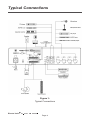
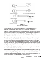
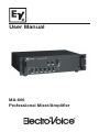
User Manual MA-606 Professional Mixer/Amplifier Electro-Voice® MA-606 User Manual Table of Contents Typical Connections ............................................................................... 3 Features ................................................................................................. 2 Description ............................................................................................. 2 Installation .............................................................................................. 3 Grounding .................................................................................. 3 Ventilation .................................................................................. 3 Key Input Connections ............................................................... 3 Typical Connectons ................................................................... 4 Output Connections ................................................................... 6 High Impedance/Constant-Voltage Systems .............................. 7 Operation ................................................................................................ 8 Front Panel Controls .................................................................. 8 Rear Panel Controls and Connections ....................................... 9 Appendix A: Limited Warranty .............................................................. 13 Exclusions and Limitations ....................................................... 13 Obtaining Warranty Service ..................................................... 13 Other Rights ............................................................................ 13 Appendix B: Safety Guidelines ............................................................. 14 AC Power Supply ..................................................................... 14 DC Power Supply .................................................................... 14 Safety Precautions................................................................... 14 Technical Specifications ....................................................................... 16 Electro-Voice® MA-606 User Manual Features • • • • • • • • • • Level controls for each input and a master volume control. Individual bass and treble tone controls. Automatic muting circuit with threshold adjustment. 600 ohm transformer-isolated line input for paging, with automatic muting of all other inputs. Low distortion. Output protection circuit. Auxiliary line level inputs with internal mixing for stereo source. Balanced line level output. Insertion point between preamp and amplifier. Phantom power on all microphone inputs enables microphones to be used without separate power supplies. Description The MA series products provide background music and allow paging in environments such as churches, small businesses, and professional offices. The inputs include 4 combination balanced or unbalanced Microphone/ AUX level connections, 2 stereo AUX summing inputs, telephone paging and Power Amp In connections. Inputs to Mic 1 can be set to automatically mute the other Mic and AUX level input channels. Input sources to Aux 1 and 2 may include: tape players, compact-disc players, AM/FM tuners, mixer-preamplifiers or wireless microphones. The telephone paging input accepts the signal from a standard 600 ohm paging line. The Power Amp In jack, along with the Preamp Out jack, is provided to insert an equalizer or other signal processing device before the power amplifier. The amplifier includes protection circuitry to prevent damage from either open or shorted speaker lines. An adjustable automatic muting circuit mutes all other inputs when the paging input is activated. Electro-Voice® MA-606 User Manual Page 2 Installation To avoid hum in the output, be certain that all input cables are physically separated from power wiring and transformers. Speaker cables should also be kept away from input cables and power cables. An example of what sources and output devices would be connected to this unit is shown in Figure 1. Grounding Ground the chassis of the unit by using the ground terminal located on the back panel. For the best grounding, connect the amplifier to an earth ground such as a cold water pipe or ground rod. If additional equipment is installed along with the amplifier, make sure their chassis are connected together to reduce noise and hum. Ventilation To remove the heat generated by the power amplifier, provide ample ventilation around the unit. Avoid blocking or impeding the vent slots in the cabinet. Locate the unit where it is free from direct sunlight, humidity, dust and vibration. Key Input Connections Microphones. The Mic inputs are for use with balanced Low Impedance (approximately 200 ohms) or unbalanced high impedance (approximately 20k ohms) microphones. For high impedance microphones, cables should be as short as possible in order to avoid loss of High Frequency response. The results will vary with the microphone and cable capacitance. However, a limit of 30 feet is recommended. The Mic inputs may be accessed by either XLR connectors or ¼ phone plugs. Figure 2 shows the wiring configurations of both unbalanced and balanced microphones using either ¼ or XLR type connectors. Page 3 Electro-Voice® MA-606 User Manual Typical Connections Figure 1: Typical Connections Electro-Voice® MA-606 User Manual Page 4 Figure 2: XLR and Jack Inputs Figure 2 shows the wiring configurations of both unbalanced and balanced microphones using either ¼ or XLR type connectors. Phantom Power: Phantom power allows the use of microphones without separate power supplies on the Mic inputs. When phantom power is on, 24 V dc is produced at pins 2 and 3 on the Mic inputs. To enable phantom power simply move the selector switch to the 24v position above the desired input connector. Microphone auto muting input: When a microphone or other source is connected to input 1 and the front panel mute switch in the on position, advance the threshold control to the point where the typical voice, and not noise in the room, will operate the mute circuit. The microphones on/ off switch may be on, with the actual voice announcement triggering the mute. If you want to defeat the muting function, place the mute switch in the off (defeat) position. Auxiliary 1 and 2: High-level unbalanced sources may be connected to the Aux 1 and 2 jacks on the back panel. Appropriate sources include a tape player, compact-disc player, AM/FM tuner, mixer-preamplifier, wireless microphone or turntable equipped with a ceramic or crystal cartridge. Use a single-conductor shielded cable. Turntables usually have a separate ground wire. Connect this wire to the ground terminal on the back panel to minimize hum. Page 5 Electro-Voice® MA-606 User Manual The set of RCA jacks (R and L) provided on the AUX 1 and 2 inputs are designed to match to the two outputs of the typical stereo source. The jacks are in parallel through internal series resistors and mix both channels. The series resistors are chosen to avoid undesirable loading effects on the output stage of typical stereo sources. Plug monaural high-level unbalanced sources into either the R or L jacks. Paging: The voice paging signal from a 600 ohm balanced audio paging line (such as a PBX system) may be connected to the aux paging input on the back panel. Power Amp In: The Power Amp In jack provides direct access to the power amplifier. It requires a line- level signal fed through a RCA type phono plug wired with a single-conductor shielded cable. Output Connections The amplifier-can accommodate both Low Impedance and high impedance constant-voltage speaker loads (25, 70.7, and 100 volt lines). There are several considerations in the connection of a speaker or multiple speakers to an amplifier: 1. Matching speaker impedance to the amplifiers rated Impedance: In general, power amplifiers deliver rated power into a rated load impedance. Lower impedances reduce the maximum available power available at rated distortion. Significantly lower impedances may cause the amplifiers protection fuses to open, especially at high volume levels. These low impedances should be avoided. 2. Power loss in speaker wire: The impedance of the speaker connecting wire would ideally be zero, so all of the amplifier output power can be delivered to the speaker load. However, the impedance of a longer speaker wire installation can become a significant proportion of the total impedance. Thus, part of the amplifier power is lost in the wire and the power to the load is reduced. Wire impedance is highest for the longest wire runs and smallest wire sizes. Table 1 shows the two wire cable (copper) lengths permissible for a number of wire sizes and speaker impedances to avoid a loss of more than 0.5 dB. For a 1 dB loss (basically imperceptible), double the wire lengths. For a 2 dB loss, multiply the lengths by 4.4. In general, note that high load impedances allow the use of longer, smaller gauge wiring. Electro-Voice® MA-606 User Manual Page 6 3. Balancing relative speaker levels: There is no easy, electrically efficient way to balance and adjust the sound levels among multiple speakers in a low impedance installation. Constant-voltage high impedance systems ease this process because they typically employ speakers equipped with transformers with multiple input taps marked in watts. Low Impedance Speakers. The low impedance ohm output terminal is provided for direct connection of one or more standard low impedance speaker systems. For example, connect a single speaker system to the common and 4 ohm terminals. Correct connection of several low impedance speakers must follow the rules of proper series and parallel impedance summation. High Impedance/Constant-Voltage Systems Installations that require high impedance speaker loads permit smaller diameter wire for a given power loss in the speaker lines. Usually, low impedance speakers are still used in such systems, but transformers are used at the speaker locations to increase the impedance to the desired value. Multiple transformer taps, labeled in watts, permit easy adjustment of the individual speaker levels. Use simple parallel connection of the transformer primaries (inputs). This eliminates the determination of load impedance and series-parallel speaker connections. For proper operation, all speakers should have transformers with the same voltage rating, i.e. 25, 70.7, or 100 volts. The total of all the power taps should be equal to or less than the amplifiers rated output power. When the total equals the rated power, the amplifier may deliver rated power to the load, depending on the input signal levels. Totals less than the rated amplifier output will not damage the amplifier since the resultant load impedance is higher than the amplifiers rated impedance and thus only reduces the power delivered at maximum amplifier level. How ever, avoid power totals greater than rated amplifier power, since the total load impedance drops below the amplifiers rated load. Preamp Out: The Preamp Out jack provides a line-level mix of the input signals, fed through a 1/4 inch phone plug wired with a single-conductor shielded cable. Use the signal at the Preamp Out jack to feed an external equalizer or signal processor whose output would connect to the Power Amp In jack. Page 7 Electro-Voice® MA-606 User Manual The preamplifier output may also be used alone to drive an additional external power amplifier with its own set of speakers. When the Preamp Out jack is used, the mixed signal to the internal power amplifier is interrupted. The balanced line level XLR output connector is ideal for feeding an external recording device or assistive listening system. When the rear panel switch is in the fixed position, the master volume control does not affect the level at this line out jack, which permits setting the tape recorders input level independent of system volume. The tape output is buffered, so that an improper load will not affect system performance. Operation Figure 3: Front Panel Layout Front Panel Controls (Refer to Figure 3) 1. Mute function switch: This switch lets you turn the Voice Priority or page ducking function on or off of input 1 (1). 2. Auxiliary 1&2 : These controls adjust the level of the two stereo summing auxiliary inputs. Input 1-4: These controls adjust the levels of the 4 multi-use inputs. 3. Music signal monitor output level control: This control is a screwdriver adjustment and lets you individually set the volume of a headphone that is connected to the MONITOR OUTPUT (4) or a small speaker connected to the 1w 8 ohm terminals on the rear panel (25). Turning the control clockwise increases the volume of the corresponding source. Electro-Voice® MA-606 User Manual Page 8 Front Panel Controls (cont) 5. Overload indicator light: When the amplifiers output overloads the OVER LOAD indicator illuminates and interrupts the output signal. The output will resume when the volume is lowered or the offending load is remove from the output line. 6. Power Switch and Power Indicator: This switch supplies power to the unit. The power indicator lights when power is applied to the unit. 7. Master: This control adjusts the level of the combined input signals to the power amplifier. 8. Treble: This control adjusts the high frequency response by providing up to 7 dB of boost or 12 dB of cut at 10 kHz. 9. Bass: This control adjusts the low frequency response by providing up to 7 dB of boost or 12 dB of cut at 100 Hz. Rear Panel Controls and Connections (Refer to Figure 4) 10. Main cord connector: This connector is for the connection of the supplied AC line cord. 11. AC fuse: The fuse can only be changed, in the event of a fault or changing the supply voltage. This service should only be done by an EV service center. 12. GND screw: In case the main outlet does not provide a ground conductor, this screw offers the possibility to ground the amplifiers metal parts. Figure 4: Rear Panel Layout Page 9 Electro-Voice® MA-606 User Manual Rear Panel Controls and Connections (cont) 13. Terminals for the DC battery supply: These two terminals allow the connection of an external 24V DC power supply such as a 24V battery. Operation of the amplifier is maintained even during a power outage, since it is automatically switched to the DC power source. 14. Output terminals: All speaker connections are made here. 25v/ 70v/100v and low impedance speaker connections are supported. For additional information on constant voltage and low impedance speaker hookups see section 4 Output Connections. 15. PRE OUT terminal: This terminal output provides the mixed audio signals of all sources that are connected to the amplifier and can be utilized to feed an external power amplifier, a signal processor or any other external appliance. The unbalanced signal is affected by the individual input controls. Before using the PRE OUT you have to remove the bridging-strip between this binding post and the MAIN IN terminal (16). 16. MAIN IN terminal: After removing bridging-strip between the PRE OUT and the MAIN IN terminals you can include an external signal processor in the audio-chain between the preamplifier and the power output stage of the power amplifier. 17. AUX 1 and AUX 2 inputs: These two RCA-type connectors let you connect the two channels of an external high-level unbalanced signal source. Such as an AM/FM tuner, a cassette deck, a CD player, etc.. An input level switch(20) is provided to properly balance the input sensitivity with a variety of sources. 18. INPUT 1- 4 jacks: These ten balanced/unbalanced combination type jack (XLR and 6.3mm) inputs are meant for the connection of-condenser type microphones that accepts 24V phantom power, dynamic microphones (30-600ohms) or a high level sound sources (e.g AM/FM tuner, cassette deck, CD player, etc.) Note: Connecting unbalanced microphones to the appliance when the phantom is switched on could lead to severe damage to the microphones and is therefore not advisable. It is absolutely mandatory to only plug or unplug a microphone cable with the phantom power turned off. Also make sure that the phantom power is turned off when utilizing microphones that are not meant to be operated with phantom power. The voltage that is present on pin2 and pin3 of the XLR-connector could lead to severe damage to the microphones. When in doubt, contact your dealer before you perform any connections. Electro-Voice® MA-606 User Manual Page 10 19. INPUT 1-4 sensitivity switches: By moving these switches onto the LINE position the corresponding input can be connected to an audio source with high level signal output. By turning these switches onto the MIC position, the corresponding input can be connected to a dynamic microphone with low impedance. By turning these switch onto 24V position, connects the 24V phantom supply on XLR of pin2 and pin3 of inputs, necessary to operate a condenser type microphone which require this type of external supply. It is recommended to operate this switch only when the master volume set on minimum. 20. AUX1-2 input sensitivity switch: By turning switch onto the 1 position, the AUX 1 , AUX 2 input is suitable for connecting to a CD player signal. The 2 position, is best used for an AM/FM tuner signal output. By turning this switch onto the3" position, the AUX1 AUX2 input is balanced for a desktop cassette player signal output. The 4 position, provides the best match for highlevel signal outputs. 21. TEL. Paging input level control: This control let you set the volume of the sound source that is connected to the Tel. Paging (23) terminals. Turning the control clockwise can increase the volume of the corresponding source. We recommend to leave the control at its minimum setting 0 when it is not used. 22. LINE OUTPUT CONNECTOR: This XLR balanced output mixes audio signals of all sources that can be utilized to feed an external tape deck or an other external appliance. The volume level can be set to a fixed level or a variable output level controlled by the master volume knob. Page 11 Electro-Voice® MA-606 User Manual 23. Input TEL.Paging: It lets you connect to an auxiliary signal (600 ohms). The input features the Voice Priority function, which overrides all other input signals, once an auxiliary message is sent. 24. Priority terminal: When short-circuiting these terminals (i.e means of using an electrical switch). The audio signals coming from AUX1, AUX2,CASSETTE and TUNER are attenuated, while the signals coming from the inputs 1-10 remain unchanged. 25. Output terminal for auxiliary loudspeaker: The terminal is meant for the connection of a small external 8 ohm loudspeaker that gets driven by an internal auxiliary power amplifier, providing a nominal output of 1 watt. Only the mixed audio signal coming from AUX1 , AUX2 CASSETTE and TUNER are included in the output signal. In addition, the output signal is controlled only by the volume controls of the AUX1,AUX2",TUNER and music signal level control(4). 26. DC switch: This switch lets you turn the battery supply on or off. Electro-Voice® MA-606 User Manual Page 12 Appendix A: Limited Warranty Electro-Voice ® amplifiers are guaranteed against malfunction due to defects in materials or workmanship for a period of three (3) years from the date of original purchase. If such malfunction occurs during the specified period, the product will be repaired or replaced (at our discretion) without charge. The product will be returned to the customer prepaid. Exclusions and Limitations The Limited Warranty does not apply to: (a) exterior finish or appearance; (b) certain specific items described in the individual product-line statements below, or in the individual product sheet or owners manual; (c) malfunction resulting from use or operation of the product other than as specified in the product data sheet or owners manual; (d) malfunction resulting from misuse or abuse of the product; or (e) malfunction occurring at any time after repairs have been made to the product by anyone other than Electro-Voice ® Service or any of its authorized representatives. Obtaining Warranty Service To obtain warranty service, a customer must deliver the product, prepaid, to Electro-Voice ® Service or to any of its authorized service representatives, together with proof of purchase of the product in the form of a bill of sale or receipted invoice. A list of authorized service representatives is available from Electro-Voice ® Service at: 12000 Portland Avenue South Burnsville, MN 55337 Phone: (877) 863-4166 Incidental and Consequential Damages Excluded Product repair or replacement and return to the customer are the only remedies provided to the customer. Electro-Voice ® shall not be liable for any incidental or consequential damages including, without limitation, injury to persons or property or loss of use. Some states do not allow the exclusion or limitation of incidental or consequential damages, so the above limitation or exclusion may not apply to you. Other Rights This warranty gives you specific legal rights, and you may also have other rights which vary from state to state. Page 13 Electro-Voice® MA-606 User Manual Appendix B: Safety Guidelines At all times, the amplifier has to be operated under appropriate conditions. This includes choosing an operation location that provides sufficient ventilation and that the device is not exposed to direct sunlight including the direct radiation or reflection from any heat source. When installing the loudspeaker systems choose a location that does not transmit extreme and/or constant vibration or other mechanical oscillation. Do not take the risk of electro-shock or shock hazard. To reduce the risk of electro-shock, all connections have to be accomplished before it is permissible to connect the amplifier to the main supply. Verify that all external connections are complete and that no short-circuits exist in any of the wiring. The overall sound reinforcement installation has to be in accordance to the laws, regulations, standards, and guidelines that are relevant and applicable in the country/locality where the equipment is going to be operated. AC Power Supply This equipment operates from a power source that does not apply more than 244 VAC between the supply conductors or between either supply conductor and ground. DC Power Supply A 24V DC power source (i.e. a battery) has to be connected to the terminals (13) that are covered by a protective lid. To reduce the risk of dropping voltage to a minimum and to eliminate the danger of damaging the battery cables by thermal overload, these cables have to be at least 2.5mm in diameter, each Switching the amplifier on or off is performed through the power switch (6). Safety Precautions 1. Please read the notes proceeded by the symbol with special attention, as they provide important safety information. 2. The power supply voltage of the amplifier has a sufficiently high value to involve the risk of electrical shock; therefore, never install, connect, or disconnect the equipment with the power supply switched on. 3. The metal parts of the equipment are earthed by means of the power cable. If the power socket used to supply power does not have an earth connection, call a qualified electrician who will earth the equipment by means of the terminal. Electro-Voice® MA-606 User Manual Page 14 Safety Precautions (cont) 4. Make sure that the power supply cable of the equipment cannot be trodden on or crushed by objects. 5. There are no parts inside that can be serviced. 6. Make sure that no objects or liquids can get into the amplifier, as this could cause a short circuit. 7. Never attempt to make any repairs that are not described in this manual. Contact your authorized service centers or highly qualified personnel when: • The equipment does not function (or functions in an abnormal way). • The power supply cable has been seriously damaged. • Objects or liquids have got into the equipment. • The equipment has been subject to heavy impact. 8. If the equipment is not to be used for long periods of time, switch it off and disconnect the power supply cable. 9. If the equipment gives off any strange odor or smoke, switch it off immediately and disconnect the power from the supply cable. Page 15 Electro-Voice® MA-606 User Manual Technical Specifications MA-606 Power Output (at 1 kHz): 60 Watts Frequency Response: 50 Hz - 15 kHz, +/-3 dB Input/Sensitiv ity /Impedance Inputs 1-4 Mi c Setti ng: 0.3 mV/600 ohm (balanced) Inputs 1-4 Li ne Setti ng: 75 mV/47 kohm (balanced) Pagi ng: -20 dBm/600 ohm (transformer i solated) Power Amp In: 1 V/10 kohm (unbalanced) Aux: 100 mV to 1 V (unbalanced) THD (at rated output): <1% at 1 kHz Signal-to-N oise R atio Mi c: <52 dB Aux: <65 dB Pagi ng: <65 dB Power Amp In: <90 dB Line Output Lev el/Impedance Preamp Output: 1 V/1 kohm (unbalanced) Balanced Li ne Output: 500 mV/47 kohm (unbalanced) Speaker Outputs: 4, 8, 16 ohm, 25, 70.7, and 100 Volt Tone C ontrols Bass: +/-10 dB at 100 Hz Treble: +/-10 dB at 10 kHz Muti ng: 40 dB attenuati on Protecti on: 3 i ndependant Slo-Blo fuses, pri mary AC and D C Power D i ssi pati on: 180 Watts Power Supply: 108-132 V AC , 50/60 Hz D i m (H x W x D ): 5.2" x 18.9" x 12.6" (133mm x 480mm x 320mm) Net Wei ght: 8.5 lbs (19.0 kg) Shi ppi ng Wei ght: 9.0 lbs (19.9 kg) Electro-Voice® MA-606 User Manual Page 16 Notes Electro-Voice® MA-606 User Manual Notes Electro-Voice® MA-606 User Manual U.S.A. and Canada: For customer orders, contact the Customer Service department at: 800/392-3497 Fax: 800/955-6831 For warranty repair or service information, contact the Service Repair Department at: 800/685-2606 For technical assistance, contact Technical Support at: 866/78-AUDIO Specifications subject to change without notice. All Other International Locations: 952-884-4051 Fax: 952-736-4212 www.electrovoice.com l Telex Communications, Inc. l www.telex.com Printed in U.S.A © Telex Communications, Inc. 2/2003 Part Number 38110-218 Rev A Electro-Voice® MA-606 User Manual