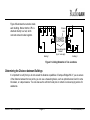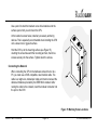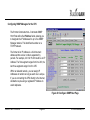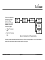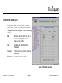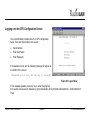
1
Wireless Local Area Network
Campus BridgeLINK™ User Guide
890-007 Rev. A 01/28/99
© 1999 RadioLAN. All rights Reserved
Notices
FCC
This equipment has been tested and found to comply with the limits for a Class A digital device, pursuant to Part
15 of the FCC rules. These limits are designed to provide reasonable protection against harmful interference in a
residential installation. This equipment generates, uses, and can radiate radio frequency energy and, if not
installed and used in accordance with the instructions, may cause harmful interference to radio communications.
However, there is no guarantee that interference will not occur in a particular installation. If this equipment does
cause harmful interference to radio or television reception, which can be determined by turning the equipment off
and on, the user is encouraged to try to correct the interference by one of the following measures:
•
•
•
•
Reorient or relocate the receiving antenna.
Increase the separation between the equipment and receiver.
Connect the equipment into an outlet on a circuit different from that to which the receiver is connected.
Consult the dealer or an experienced radio/TV technician for help.
FCCID: MCIPUNIIT
FCC Rule Part(s): 15
Frequency (MHz): 5775, 5200, 5300
Equipment Class
890-007 Rev. A 01/28/99
Low Power Communication Device Transmitter
Page ii
© 1999 RadioLAN.
Remarks:
UNII WLAN and Class A PCMCIA Card
Maximum Output Power: 50 mW
Notes:
This device has shown compliance with new rules adopted under Docket 87-389 and is not affected by
Section 15.37, transition rule.
Each radio is marked with its operating frequency.
FCC regulations require that this device be professionally installed by a person knowledgeable in electronics and
trained in the correct installation of this device.
UL safety listing requires that the installation conform to the National Electrical Code sections 810 and 820.
All interface cables must be shielded.
This device complies with Part 15 of FCC rules. Operation is subject to the following two conditions: 1) this device
may not cause harmful interference, and 2) this device must accept any interference received, including
interference that may cause undesired operation.
890-007 Rev. A 01/28/99
Page iii
© 1999 RadioLAN.
Disclaimer
The instructions in this document have been carefully checked for accuracy and are presumed to be reliable.
RadioLAN and its writers assume no responsibility for inaccuracies and reserve the right to modify and revise this
document without notice.
It is always our goal at RadioLAN to supply accurate and reliable documentation. If you discover a discrepancy in
this document, please e-mail your comments or suggested corrections to [email protected].
No part of this publication may be placed in a retrieval system, transmitted, or reproduced in any way, including,
but not limited to, photograph, photocopy, computer disk or other record, without prior agreement and written
permission from:
RadioLAN
455 De Guigne Drive
Sunnyvale, CA 94086
© 1999 RadioLAN, Sunnyvale, CA, USA. All rights reserved.
890-007 Rev. A 01/28/99
Page iv
© 1999 RadioLAN.
Trademark Disclosures
RadioLAN has made every effort to provide disclosures when using trademarks owned by other companies.
Trademarked designations appear throughout this publication. The publisher states that it is using the
designations only for editorial purposes, and to the benefit of the trademark owner with no intent to infringe upon
that trademark. The following trademarks are found in this manual:
Microsoft™, Windows for Workgroups™, Windows 95™, Microsoft Internet Explorer™, and Windows NT™ are trademarks of
Microsoft Corporation.
Netscape™ is a registered trademark of The Netscape Corporation;
Novell™ and NetWare™ are trademarks of Novell, Inc.
Xerox™ is a trademark of Xerox Corporation.
IBM™ is a trademark of International Business Machines.
10BaseRadio™ and RadioLAN/10™ are trademarks of Radio/LAN.
Java™ is a trademark of Sun Microsystems, Inc.
Manual Conventions
The following text formats are used throughout this manual:
References to other locations in the manual or to other manuals provided by RadioLAN are italicized.
Narrow Bold Letters describe buttons and fields on the screen.
SMALL CAPITAL LETTERS describe Screen Names or Screen Tab Names.
Bold and Italicized Letters indicate important information.
890-007 Rev. A 01/28/99
Page v
© 1999 RadioLAN.
Table of Contents
Notices ...................................................................................................................................................................ii
FCC........................................................................................................................................................................ ii
Disclaimer .............................................................................................................................................................. iv
Trademark Disclosures ............................................................................................................................................ v
Manual Conventions ................................................................................................................................................ v
Introduction ......................................................................................................................................................... 1
The Campus BridgeLINK™ System.......................................................................................................................... 3
The Directional Antenna........................................................................................................................................... 8
A Typical Campus BridgeLINK™ Application ........................................................................................................... 10
Determining the Distance between Buildings ........................................................................................................... 11
Initial IP Address Setup ......................................................................................................................................... 12
Installing the CPU ............................................................................................................................................15
Tools You Will Need .............................................................................................................................................. 15
Locating the CPU .................................................................................................................................................. 16
Mounting the CPU ................................................................................................................................................. 17
Grounding Considerations...................................................................................................................................... 20
Installing the Antenna.....................................................................................................................................21
890-007 Rev. A 01/28/99
Page vi
© 1999 RadioLAN.
A Brief Word About Safety...................................................................................................................................... 21
Choosing the Best Mounting Height ........................................................................................................................ 22
Sighting Each Campus BridgeLINK™ Antenna ........................................................................................................ 23
Apply Power to the CPU......................................................................................................................................... 25
Adding Security to the Wireless Network ................................................................................................................. 26
Local Management ................................................................................................................................................ 26
Dual Remote Management: HTML and SNMP......................................................................................................... 26
Using the Campus BridgeLINK™ Manager...............................................................................................28
The CPU Web Site ................................................................................................................................................ 28
Browsing the Network for the CPU.......................................................................................................................... 29
Logging onto Campus BridgeLINK™ Manager......................................................................................................... 29
Campus BridgeLINK™ Manager Site Layout ........................................................................................................... 31
Aiming the Directional Antennas ............................................................................................................................. 33
Setting Up Security Features.................................................................................................................................. 35
Setting Up SNMP Capabilities ................................................................................................................................ 36
Setting the CPU’s Mode of Operation...................................................................................................................... 47
Securing the CPU with Data Encryption .................................................................................................................. 48
Bridging the Link and 10BaseT Networks ................................................................................................................ 49
Managing Packet Flow Through the CPU ................................................................................................................ 57
Interrogating the System for Performance Information.............................................................................................. 67
Upgrading System Software ................................................................................................................................... 74
Saving or Rejecting Configuration Setting Changes ................................................................................................. 77
Resetting the CPU ................................................................................................................................................. 79
890-007 Rev. A 01/28/99
Page vii
© 1999 RadioLAN.
Recording Important System Information.................................................................................................80
Viewing the System Log......................................................................................................................................... 83
Managing the CPU Locally ............................................................................................................................84
CPU Local Management ........................................................................................................................................ 86
Hot Keys............................................................................................................................................................... 86
Logging onto the CPU Configuration Screen............................................................................................................ 87
Using the Main Menu ............................................................................................................................................. 89
Working with the System Configuration Menu.......................................................................................................... 91
Configuration Manager Menu Items ........................................................................................................................ 95
Troubleshooting.............................................................................................................................................108
Glossary............................................................................................................................................................110
Appendix A: Indicators, Switches, and Connectors.............................................................................113
Indicators ............................................................................................................................................................ 113
MDI/MDI-X Switch ............................................................................................................................................... 114
I/O Connectors .................................................................................................................................................... 115
Serial Port Connector ...................................................................................................................................116
Appendix B: Technical Specifications .....................................................................................................117
Network Protocol ................................................................................................................................................. 117
Standards Support............................................................................................................................................... 117
890-007 Rev. A 01/28/99
Page viii
© 1999 RadioLAN.
Electrical Specifications........................................................................................................................................ 117
Physical Specifications......................................................................................................................................... 118
Environmental Specifications................................................................................................................................ 118
Electromagnetic Emissions .................................................................................................................................. 119
Safety Agency Approvals ..................................................................................................................................... 119
Getting Technical Support...........................................................................................................................120
890-007 Rev. A 01/28/99
Page ix
© 1999 RadioLAN.
Notes
890-007 Rev. A 01/28/99
Page x
© 1999 RadioLAN.
Introduction
Historically, connecting two buildings to allow networking
between two local area networks required the expense
and effort related to running a cable from one building to
another. This may have involved installing an aerial cable
or digging a trench and installing conduit and wiring
between the two buildings, which is time-consuming,
labor-intensive, and costly.
After installation, cable degradation, due to moisture,
corrosion, or alterations in landscaping, can compromise
the network connection between the two buildings.
Repairing and replacing cable runs is also costly, timeconsuming, and labor-intensive.
RadioLAN overcomes these difficult installation issues
with its Campus BridgeLINK™ product line. This exciting
new technology easily connects two buildings, using radio
frequency technology. Because this technology uses
radio frequency to make the connection between the
buildings, cable runs, conduit, trenching, and labor
involved with these activities are no longer required.
890-007 Rev. A 01/28/99
Page 1
Figure 1: Campus BridgeLINK™ Products
© 1999 RadioLAN, Inc.
RadioLAN allows you to connect two buildings, which are up to one mile apart, using a Campus BridgeLINK™
Processor Unit (CPU), a Companion Radio Module (CRM), and an 8.86” square directional antenna for each
building link. When using the Campus BridgeLINK™ application, you need only install the components at each
building, aim the antennas toward one another, and power the system on. The only requirements for each
building location are Campus BridgeLINK™ system components and access to network cabling and power.
The directional antenna and its cabling is weatherproof, small-profile, and sturdy. Because the directional antenna
allows for a 19° angle of operation, aiming the antennas so they point toward one another is nearly effortless.
Connecting two networks in two locations using the old-fashioned, hard-wired method could take days,
considering the labor intensive effort needed. When using Campus BridgeLINK, the task is simplified. The task of
connecting two networks is reduced to mere hours, without the back-breaking labor related to trenching, laying
conduit and then cleaning up the landscaping mess afterward.
In this section, we will introduce you to the concepts of Campus BridgeLINK™ communication, using a RadioLAN
Wireless Campus BridgeLINK™ system. Here, you will become familiar with the CPU, the CRM, the directional
antenna, and the signal analysis tools.
890-007 Rev. A 01/28/99
Page 2
© 1999 RadioLAN, Inc.
The Campus BridgeLINK™ System
Local Port
The Campus BridgeLINK system includes the Campus
BridgeLINK™ Processor Unit (CPU) with a mounting bracket,
a Companion Radio Module (CRM), and a directional antenna.
Also included is the power transformer that you can plug into a
non-switched electric outlet. You can install these items in
plain view, hidden away in a closet, or above ceiling tile.
Campus BridgeLINK™ Processor Unit (CPU)
The CPU features a number of LED indicators, switches, and
jacks that allows you to connect the module to external
devices and help you see the CPU status.
LED Indicators
The face of the CPU features four LED indicators:
•
The green Power LED illuminates when power is applied
to the CPU. As long as the CPU is powered, this LED is
normally illuminated.
890-007 Rev. A 01/28/99
Page 3
10BaseT Port
Status LEDs:
Fault
MDI/MDI-X
Selector
Power
Jack
Status 2
Status 1
Power
Radio
Mounting
Bracket
Figure 2: CPU (Campus BridgeLINK™
Processor Unit)
© 1999 RadioLAN, Inc.
•
The amber Fault LED illuminates for several seconds during the power-on diagnostic sequence. When the
CPU is operating, this LED is normally extinguished.
•
The green Status 1 LED illuminates when the CPU detects the presence of the distant CPU. When the CPU
is operating, this LED normally illuminates when the near and far CPUs are active.
•
The green Status 2 LED illuminates when the CPU detects the presence of data passing through the wireless
link. During normal CPU operation, this LED flickers when near and far CPUs are active.
One end of the CPU features a button and two ports:
•
MDI/MDI-X selector button
•
10BaseT port
•
Local port
MDI/MDI-X Switch
The MDI/MDI-X selector button switches the jack’s pin assignment of transmit and receive data wire pairs for the
10BaseT port.
Use MDI-X configuration when the remote end of the wires is connected to a network station. For example, use
this setting when connecting the CPU to a 10BaseT Network Interface Card or to an MDI port with a 10BaseT
concentrator.
Set the switch for MDI configuration when the remote end of the wire is connected to a 10BaseT concentrator or a
hub.
890-007 Rev. A 01/28/99
Page 4
© 1999 RadioLAN, Inc.
10BaseT Port Jack
Next to the MDI/MDI-X selector button you will find the 10BaseT port. The 10BaseT port interfaces the CPU to its
local area network. The 10BaseT port is RJ45-compatible, which allows an eight-wire connection to a network
hub or other hard-wired external device.
10BaseT LED Indicators
On the upper left and right corners of the 10BaseT port are green LEDs which indicate transmit and receive status
from the network.
When the CAR LED illuminates, this indicates that the Ethernet carrier is active.
When the ACT LED illuminates, this indicates Ethernet activity on the network. This LED flickers during normal
operation.
Local Port Jack
Located on the opposite end from the selector button, on the same face of the CPU, is the local port jack. The
local port is compatible with RJ11 connectors and allows connection to a local terminal. When you need a local
terminal connection, use the local terminal to configure the CPU.
890-007 Rev. A 01/28/99
Page 5
© 1999 RadioLAN, Inc.
CRM Port
At the opposite end of the CPU, there is a female 15-pin
D connector. The connector allows you to connect the
CRM to the CPU, using the cable that is attached to the
Radio Unit.
Mounting Bracket
The mounting bracket is specially shaped so that it
allows the CRM to slide into the mounting bracket
before securing the CPU to a flat surface.
CRM
Mounting
Bracket
CPU
CRM Port
Figure 3: CRM (Companion Radio Module) Port
890-007 Rev. A 01/28/99
Page 6
© 1999 RadioLAN, Inc.
The Companion Radio Module (CRM)
The CRM interfaces the CPU with the directional antenna. The
CRM is small, durable, and designed to insert easily into the
mounting bracket that is attached to the CPU.
Directional Antenna
Connector (Type N)
On one end of the CRM, there is a Type N connector and an LED
indicator. The Type N connector attaches the CRM to the
directional antenna.
The LED illuminates amber when the CRM is transmitting data. It
illuminates green when the CRM is receiving data.
Activity
LED
CPU
Connector
Figure 4: CRM (Companion
Radio Module)
890-007 Rev. A 01/28/99
Page 7
© 1999 RadioLAN, Inc.
Power Transformer
The power transformer provides an easy connection to electrical outlets. One end of
the transformer has a power cable with a connector that is compatible with the
CPU’s power jack. The other end plugs into an electrical outlet. RadioLAN
recommends using a non-switched electrical outlet for connection to the CPU.
Figure 5: Power
Transformer
The Directional Antenna
The directional antenna assembly includes the directional antenna and a mounting
clamp. The directional antenna is a 18dbi-gain, small-profile directional antenna. It is
8.86 inches square, and mounted on a pivoting base.
Figure 6: Directional
Antenna
890-007 Rev. A 01/28/99
Page 8
© 1999 RadioLAN, Inc.
Antenna Cable
The antenna cable provided is a 15-foot, low-loss cable. It is made
of fire retardant material, and is UV stabilized. Cold-shrink tubing is
supplied to cover the antenna end connector after connection to the
cable. See the installation instructions packaged with the shrink
tubing for installation directions.
Type N Connectors
Figure 7: Low-Loss RF Cable
890-007 Rev. A 01/28/99
Page 9
© 1999 RadioLAN, Inc.
A Typical Campus BridgeLINK™ Application
Figure 8 shows a typical Campus
BridgeLINK application in which two
buildings, with local area networks in
each, are located up to one mile away
from one another. Notice that there are
no solid obstructions between the two
buildings and that each building
antenna points toward the other.
8.8“ Directional Antenna
Up to 1 Mile Apart
Because the system uses radio
frequency to establish the connection
between the two buildings, it is
important to avoid blocking the radio
link with any objects, such as a trees,
buildings, walls, or items that are
attached to the building walls, such as stairwells,
fire escapes, or other antenna equipment.
890-007 Rev. A 01/28/99
Page 10
Figure 8: A Typical Campus BridgeLINK™
Application
© 1999 RadioLAN, Inc.
Figure 9 illustrates the networks inside
each building. Notice that the CPU is
attached directly to a hub, which
connects network nodes together.
Hub
Wireless
Link
Hub
CPU
CPU
Campus BridgeLINK
Modules
(Up to 1 mile apart)
Building 1
Building 2
Figure 9: Linking Networks in Two Locations
Determining the Distance between Buildings
It is important to verify that you do not exceed the distance capabilities of Campus BridgeLINK. If you are unsure
of the distance between the two points, you can use a measuring device, such as optical devices found in some
binoculars, or a tape measure. You can also see the architect’s site plan or contact a local surveying service for
assistance.
890-007 Rev. A 01/28/99
Page 11
© 1999 RadioLAN, Inc.
Initial IP Address Setup
Before you can use the TCP/IP management services of
a CPU, it must contain a valid network IP Address. There
are three ways to assign an IP Address to the CPU:
•
Connection between the CPU and a PC on the same
local LAN segment
•
A VT-100 terminal connection to the CPU Local Port
This section describes in detail each method for assigning
the CPU an IP Address.
890-007 Rev. A 01/28/99
Page 12
CPU
10BaseT Network
Interface Card
10BaseT Ethernet
or Crossover Cable
Power
Adapter
Figure 10: Quick Configuration
© 1999 RadioLAN, Inc.
Temporarily Connect the CPU
To use the IP ASSIGN Utility, you must first obtain a PC with a 10BaseT Network Interface Card that has its own
IP Address. The PC must not be running a DHCP Server while performing this procedure.
1.
Determine the method that you are using to assign the IP Address:
Using a PC with a 10BaseT Network Interface Card: If you installed the IP ASSIGN Utility in a PC with a
10BaseT Network Interface Card, connect an RJ45, 10BaseT cable between the CPU and the jack on the
PC’s Network Interface Card.
Using the CPU Local Port: If you are using the local port, connect the serial port from a VT-100 terminal to
the CPU local port.
2.
Connect the Radio Unit to the CPU.
3.
Connect the CPU’s power adapter to the power jack on the CPU.
4.
Plug the CPU’s power adapter into a 115VAC electrical outlet.
The CPU’s Power LED illuminates.
If you are using a PC with a network interface card, see Using the IP ASSIGN Utility to Assign the CPU’s IP
Address on page 14. If you are using the CPU local port, see Managing the CPU Locally on page 86.
890-007 Rev. A 01/28/99
Page 13
© 1999 RadioLAN, Inc.
Using the IP ASSIGN Utility to Assign the CPU’s IP Address
RadioLAN provides the IP ASSIGN Utility diskette with your package. The utility allows you
to assign an IP Address to the CPU quickly.
To install the IP ASSIGN Utility and assign an IP Address to the CPU, follow these steps
from a PC connected to the CPU:
1.
Insert the IP ASSIGN Utility diskette into drive A.
2.
Using the Windows RUN command, type A: IP ASSIGN and click OK.
The utility starts and begins searching the local LAN segment for any CPUs that are not
configured with an agent IP Address.
The utility returns a page listing of the Media Access Control (MAC) Addresses for all
non-configured CPUs on the LAN segment.
Figure 11:
Configuration
Disk
3.
Highlight the MAC Address for the CPU that you want to configure.
4.
Enter the desired temporary IP Address for the CPU. Later, you can permanently set it using the IP
PARAMETERS page.
The utility checks the IP Address to verify its validity. If the newly entered IP Address is valid, the utility
assigns it to the CPU and prompts you to configure the CPU using your network browser.
5.
Choose Yes to launch your default network browser, and press Enter.
The utility displays the login page for the CPU configuration program.
890-007 Rev. A 01/28/99
Page 14
© 1999 RadioLAN, Inc.
Installing the CPU
When installing a CPU you must mount it onto a wall or a ceiling. You must locate the CPU at a distance from the
antenna that is no farther than the cable will allow. The cable length is a maximum of 15 feet; this means you
must consider all bends in the cable when determining your distance.
You must also locate the CPU in an area from which it has access to local network cabling and electricity. Before
selecting an electrical outlet for use in powering the CPU, verify that the electrical outlet is non-switched (for
example, it is not attached to a wall switch). You should also consider placing the CPU in a location where it is out
of reach of the general public.
FCC regulations require that this device be professionally installed by a person knowledgeable in
electronics and trained in the correct installation of this device.
All interface cables must be shielded.
Tools You Will Need
To install the CPU, you will need the following tools: drill, drill bit, screwdriver, screws, pencil, measuring tape.
890-007 Rev. A 01/28/99
Page 15
© 1999 RadioLAN, Inc.
Locating the CPU
After verifying that the
CPU is located near a
power source and network
cabling, and is within the
15-foot cable distance
constraint of the antenna,
you must install the CPU
securely to the mounting
surface (for example, a
wall or ceiling).
Directional Antenna
Switched
Outlet
Campus
BridgeLINK
Module
10BaseT HUB
1 2 3 4
5 6
Non-switched
Outlet
Wired Network Server
Figure 12: Locating the CPU Closely to
Network, Power, and the Antenna
890-007 Rev. A 01/28/99
Page 16
© 1999 RadioLAN, Inc.
Mounting the CPU
When mounting the CPU, you must follow these steps.
Before mounting the CPU to the mounting surface,
connect the connector at the end of the CRM’s cable to
the 15 pin D connector on the CPU (see Figure 13).
Route the antenna cable from the directional antenna to
the CRM, and slip the cold-shrink tubing over the end of
the cable before connecting the cable to the antenna.
Connect the cable to the CRM, using a clockwise rotation.
Tighten the antenna connector so that it is snug but does
not strip the threads of the connector on the CRM.
Complete the shrink tubing installation by following the
instructions provided with the tubing.
Figure 13: Connecting the Antenna Cable to
the CRM
890-007 Rev. A 01/28/99
Page 17
© 1999 RadioLAN, Inc.
Orient the CRM so that its cable does not cross over the mounting
brackets and then insert the CRM into the mounting bracket so that it is
flush with the rim of the bracket (see Figure 14).
Orient the CPU on the mounting surface in the location where you would
like it to be attached.
Figure 14: Inserting the CRM into the Bracket
890-007 Rev. A 01/28/99
Page 18
© 1999 RadioLAN, Inc.
Use a pencil to mark the brackets screw hole locations onto the
surface upon which you will mount the CPU.
At the location’s screw holes, install any necessary anchoring
devices. This is especially recommended when installing the CPU
onto a sheet-rock or gypsum surface.
Hold the CPU up to the mounting surface (see Figure 15),
orienting the screw holes with the mounting anchors, then drive
screws securely into the surface. Tighten down the screws.
Connecting the Network
When connecting the CPU to the hardware network hub or to a
PC, you must use a RJ45-compatible, dual modular cable. The
cable is an eight-wire, twisted-pair cable and must not exceed the
distance limitations provided by the IEEE 802.3 standard. After
routing the cable to the network, insert the modular connector into
the port on the CPU.
Figure 15: Marking Screw Locations
890-007 Rev. A 01/28/99
Page 19
© 1999 RadioLAN, Inc.
Grounding Considerations
RadioLAN recommends that you properly ground the directional antenna as
described in mounting hardware installation instructions and required by
your local ordinances.
RadioLAN recommends that you connect the antenna assembly to a ground
rod driven a minimum of 10 feet into the soil. For proper grounding of the
antenna and cable follow Section 810 of the National Electrical Code. Use
UL-listed ground clamps and lugs.
Dish Mounting
Hardware
Ground
Clamp
Approved
Ground
Figure 16: Acceptable Ground Source
890-007 Rev. A 01/28/99
Page 20
© 1999 RadioLAN, Inc.
Installing the Antenna
There are many methods for mounting the antenna onto
a wall. The assembly includes a U-bolt that allows you to
connect the directional antenna to a standard size
mounting assembly that is used for other directional
antenna applications. Directional antenna wall-mounting
assemblies are available at your local computer store or
retailer who sells directional antennas or satellite
services. The directional antenna uses a U-bolt with a
nut on each end. Slide the mounting clamp through the
two eyeholes on the backside of the directional antenna,
then secure the clamp to the mounting equipment that
you chose.
U-Bolts
Directional
Antenna
Typical Mounting
Hardware
Figure 17: Attaching the Directional to a
Typical Mount
A Brief Word About Safety
If you chose to mount the antenna high up on a wall,
make sure that you use the appropriate type of ladder.
Follow ladder safety tips provided by its manufacturer. RadioLAN recommends that you have a partner available
to secure the ladder and to offer assistance while you are on the ladder. RadioLAN recommends that you not
mount the unit during stormy weather, on windy days, or anywhere near electrical cables.
890-007 Rev. A 01/28/99
Page 21
© 1999 RadioLAN, Inc.
Choosing the Best Mounting Height
Make sure that you choose the appropriate mounting height for the directional
antenna. You must consider the cable distance between the directional
antenna and the CPU, and the level of accessibility for routing cable and
mounting the CPU.
If the structure has an eave, RadioLAN recommends that you not place the
antenna up so high into the eave that the roof blocks a line-of-sight view to
the antenna on the distant Campus BridgeLINK™ building. Before securing
the antenna to the wall, verify that you can see the distant directional antenna
and that the line of site is clear of all obstructions.
Figure 18: Minimum Height from Ground
890-007 Rev. A 01/28/99
Page 22
© 1999 RadioLAN, Inc.
Sighting Each Campus BridgeLINK™ Antenna
Once you have installed and grounded the mounting bracket assembly (provided by others), you can point the
directional antenna toward the location of the distant antenna.
Tools You Will Need
To site the antenna properly, you will need to
have a crescent wrench, a carpenter’s square, a
ladder, and a helper.
Adjusting the Antenna’s Direction
To adjust the antenna’s direction, you will:
1.
2.
3.
Turn to adjust
the azimuth
Loosen nut and
then tilt to adjust
the elevation
Tilt Mount
Carpenter’s
Square
Loosen the U-bolts to turn the antenna into
the correct side-to-side direction (azimuth).
Loosen the nut on the tilt mount to adjust
the antenna to the proper elevation.
Tighten all nuts and bolts to safeguard the
antenna against direction changes during
high winds.
Antenna
Fixed Base
Figure 19: Aligning the Antenna
890-007 Rev. A 01/28/99
Page 23
© 1999 RadioLAN, Inc.
Sighting Procedure
Campus BridgeLINK™ uses a 19° angle of reception for each of its antennas. This means that, from the center of
the directional antenna, you can angle away from your target for as much as 9.5° in any direction. This makes it
very easy to site the two antennas and align them properly.
Sighting greater distances: If your application requires that the buildings are nearly one mile apart, it may be
difficult to visually resolve the distant Campus BridgeLINK™ antenna. In these cases you may need a compass,
GPS, local maps, or other direction calibration equipment.
Greater distances increase probability for line-of-site blockages: As the distance between buildings
increases, there is a greater likelihood for objects appearing that block the line-of-site between Campus
BridgeLINK™ sites. When planning applications with greater distances, avoid problems caused by new
construction, or a large grove of trees between the two sites by placing the antenna higher. This decreases the
likelihood for line-of-site blockages through time.
Eyeball the Direction
Using a carpenter’s square (see Figure 19) align the square across the directional antenna’s surface and adjust
the antenna so that the carpenter’s square points toward the distant Campus BridgeLINK™ antenna location.
After aligning the antenna, tighten the nuts on the mounting assembly so that it stays affixed in this direction and
cannot be easily blown out of alignment by wind or heavy rain.
Next, connect the antenna cable to the back of the antenna. You can further align the two antennas, using the
Campus BridgeLINK™ Manager. See Aiming the Directional Antennas on page 33 for more information.
890-007 Rev. A 01/28/99
Page 24
© 1999 RadioLAN, Inc.
Apply Power to the CPU
After verifying that the antenna cable is properly attached to the
antenna and the CRM, and after making sure that the CRM is
properly attached to the CPU, you can apply power to the CPU
following these steps:
1.
Connect the CPU to the power transformer.
2.
Connect the power transformer to the electrical outlet.
If the CPU is properly powered, you should notice that the
green Power LED illuminates.
890-007 Rev. A 01/28/99
Page 25
2
1
Figure 20: Power Connection Sequence
© 1999 RadioLAN, Inc.
Adding Security to the Wireless Network
As an option, you can contact RadioLAN to enable the Data Encryption feature. This feature secures the wireless
link by setting an encryption key that protects your sensitive data on the wireless link. When you enable Data
Encryption, only CPUs that share the same encryption key can share data.
Local Management
The CPU includes a built-in serial port for connecting a VT-100 terminal or a modem. Using a terminal allows you
serial access configuration and system performance pages. Connecting a modem to the serial port allows you to
dial into the CPU from a remote location to log in and configure or view system performance.
Dual Remote Management: HTML and SNMP
The CPU contains an SNMP (Simple Network Management Protocol) agent. When a remote SNMP Manager
interrogates the agent, the agent presents system configuration and statistical information by way of the MIB
(Management Information Base). While connected to the agent through the network, the manager receives the
MIB and can see wireless network performance information.
When you use your SNMP Manager, you can make changes, see current status, and review new network history.
The CPU now supports SNMP management, using the standard MIB for selected functions. Contact RadioLAN
for a copy of the CPU’s MIB object functions.
890-007 Rev. A 01/28/99
Page 26
© 1999 RadioLAN, Inc.
The CPU’s interface includes system security authentication passwords, so only remote users with the correct
password can access and configure the CPU. The CPU offers up to three security access passwords, each
configurable for read and/or write rights.
System Requirements
To successfully place a CPU into operation, you must meet the following requirements:
•
The CPU must connect directly to a 10BaseT Network.
•
The CPU must be located within one mile of another Campus BridgeLINK™ CPU.
•
The network must use TCP/IP to communicate, using remote management.
Browser Requirements
To access the CPU by way of a 10BaseT Network, you must use a browser that is compatible with HTML, frames,
and Java™ script language, such as Netscape™ 4.x or Microsoft Internet Explorer™ 4.x provides.
890-007 Rev. A 01/28/99
Page 27
© 1999 RadioLAN, Inc.
Using the Campus BridgeLINK™ Manager
The Campus BridgeLINK™ Manager allows you to interrogate and interact with the CPU from a remote location
on the IP network, using a Web browser to communicate with the CPU. Your browser must support Java script
and frames. After launching your browser, enter the IP Address for the CPU. If you just set up the CPU for the first
time, you should have already assigned the CPU’s IP Address using the IP ASSIGN Utility or with the VT-100
terminal.
This section discusses how to find the CPU on your network, how to log onto the CPU, and how to use the CPU
Web Site.
The CPU Web Site
The Campus BridgeLINK™ Manager allows you to view pages which contain configuration information about the
CPU. Using the Web Site, you can assign passwords, set up IP Addresses for the CPU and SNMP management
stations, set address filters, and view system performance statistics.
When using the Campus BridgeLINK™ Manager to make changes, edit your choices on the site’s pages, then
accept all session changes by accessing the SYSTEM C ONFIGURATION - CONFIGURATION C HANGES PAGE. This
causes the CPU to store configuration changes. Changes take effect after you save the changes and reset the
CPU (see Saving or Rejecting Configuration Setting Changes on page 77.
890-007 Rev. A 01/28/99
Page 28
© 1999 RadioLAN, Inc.
Browsing the Network for the CPU
To find the CPU on your network, follow these steps:
1. Open your Web browser
2. In the browser’s address field, type the IP Address for the
CPU, then press Enter.
The browser searches the network for the CPU. When it finds
the CPU, the E NTER N ETWORK PASSWORD page appears.
Logging onto Campus BridgeLINK™ Manager
The ENTER N ETWORK PASSWORD page provides security to
CPU configuration items. There are two fields on the page:
•
Figure 21: Logging On
User Name
• Password
If this is the first time that you log on: This screen appears only after User Names and passwords are stored in
the CPU (see Setting Up Security Features on page 35 for more information). If no User Names and Passwords
are stored in the CPU, the program bypasses the ENTER N ETWORK PASSWORD screen and displays the main
program screen
890-007 Rev. A 01/28/99
Page 29
© 1999 RadioLAN, Inc.
Product ID
The Product ID field is a read-only field that reports the Product ID for the CPU.
Enter User Name
The Enter User Name field is an entry field where you enter your user name to gain access to the configuration and
diagnostic pages. Only entries matching those programmed into the SYSTEM CONFIGURATION: ACCESS S ECURITY
page are allowed access to the program.
Enter Password
The Enter Password field allows you to enter your user password for access to configuration and diagnostic pages.
Enter your password here and then press Enter to go to the next page.
If the user name and password match those stored in the ACCESS S ECURITY page, you will be allowed to view and
edit items on the page. If you make entries that do not match those stored in the program, you will remain on the
ENTER N ETWORK PASSWORD page.
890-007 Rev. A 01/28/99
Page 30
© 1999 RadioLAN, Inc.
Campus BridgeLINK™ Manager Site Layout
The Campus BridgeLINK™ Manager Site uses frames that allow you to size
and view the pages according to your needs. The main menu is made up of
the following items:
Main
Menu
Node
Discovery
System
Features
System
Configuration
•
Node Discovery–-Checks the quality of the link.
•
System Features–-Enables enhanced CPU features.
•
System Configuration–-Configures the CPU for use with your 10BaseT
Network and wireless link.
•
System Statistics–-Displays system performance.
•
System Status–-Displays the system’s current status.
•
Antenna Aiming–-Fine tune your directional antenna.
•
Reset–-Resets the CPU.
System
Statistics
System
Status
Antenna
Aiming
Reset
Figure 22: Campus
BridgeLINK™ Manager Main
Menu
890-007 Rev. A 01/28/99
Page 31
© 1999 RadioLAN, Inc.
Figure 23 shows the main screen. The left side of the
page contains a menu that allows you to select the
screen that you want to view or change.
Menu items that have a [+] next to them have
submenu items that lead to specific pages. After
selecting a submenu item, the right frame of the page
changes to display program items and other
information. You can size the frames by clicking on the
divider line and dragging the line to the size that meets
your needs.
Figure 23: Campus BridgeLINK™ Manager Main
Page
890-007 Rev. A 01/28/99
Page 32
© 1999 RadioLAN, Inc.
Aiming the Directional Antennas
If you are installing the Campus BridgeLINK™ system,
or if you want to improve the alignment of the two
directional antennas, use the ANTENNA AIMING page to
find the distant antenna’s signal, and to improve signal
quality. The page includes the following items:
•
•
•
•
•
•
•
•
•
•
Explicit Address check box
CPU Name drop-down list box
Frame Size field
Estimated Distance list
Successful % field
Best field
Worst field
Sound check box
Start button
Stop button
•
Save Distance Parameter button
890-007 Rev. A 01/28/99
Figure 24: Antenna Aiming Page
Page 33
© 1999 RadioLAN, Inc.
Selecting the Distant CPU’s Address
The ANTENNA AIMING page allows you to select the remote CPU’s name or explicit address. If you place a check in
the Explicit Address check box, the CPU Name list box displays the field to enter the MAC Address of the distant
CPU. Clearing the Explicit Address check box displays the port name of the distant CPU. See Port Name on page
55 for information about setting the CPU’s Port Name field.
Setting the Frame Size
Select the desired frame size that you want to use for testing purposes. Similar to a PING, adjusting the frame
size can vary test results. Enter your selection in the Frame Size field.
Setting the Estimated Distance between Antennas
The Estimated Distance list allows you to choose the estimated distance between links. Click a value in the list to
make your selection. After testing, you can save the entries on the page by clicking the Save Distance Parameter
button.
Starting and Stopping the Test
You can begin and end the testing at any time. Click on the Start button to begin the test. Click on the Stop button
to end the test.
Viewing or Hearing Status of the Link
Once you have started the test by clicking the Start button, you can view test results by viewing the Successful %
field. You can also view the best and worst-case scenarios by looking at results that appear in Best and Worst
fields. This page features audio status of the Successful % field when you place a check mark in the Sound check
box.
890-007 Rev. A 01/28/99
Page 34
© 1999 RadioLAN, Inc.
Setting Up Security Features
The ACCESS S ECURITY PAGE allows you to specify up to
three user names and passwords, which allow entry into
the configuration and diagnostic pages. To get to this
page, select Access Security from the System
Configuration menu.
User Logon Name Fields
The User Logon Name fields allow you to enter from 1 to
12 characters to specify a user name. You can use
letters and numbers for this entry. This entry is casesensitive, so be sure to note the user name exactly as
you enter it here.
Make your entry, then press the Tab key to move to the
User Logon Password field.
The User Password and Retype Password Fields
The User Logon Password and verification fields allow you
to enter from 1 to 12 characters to specify the user
password. You can use letters and numbers for this
entry. This entry is a case-sensitive field, so be sure to
note the user password exactly as you enter it here.
890-007 Rev. A 01/28/99
Page 35
Figure 25: Access Security Page
© 1999 RadioLAN, Inc.
Setting Up SNMP Capabilities
The CPU contains an SNMP agent, which processes information from the CPU MIB. The MIB (Management
Information Base) contains system status information, which allows for remote queries for system status and
control with SNMP management applications from remote locations on the network.
There are three basic information pages related to SNMP management:
•
Administration Parameters
•
IP Parameters
•
SNMP Parameters
After configuring each of these pages, you will be able to access the CPU from any location on the 10BaseT
Network if you have rights to do so.
890-007 Rev. A 01/28/99
Page 36
© 1999 RadioLAN, Inc.
Administration Parameters
The ADMINISTRATION PARAMETERS PAGE allows you to
specify system identification information. This
information is useful to allow remote network
administrators to determine the:
•
System Name
•
System Contact
•
System Location
These fields are described in the following sections.
To access this page, select Administration Parameters
from the System Configuration menu.
This page also includes three buttons:
Reload
OK
Use Default
890-007 Rev. A 01/28/99
Figure 26: Administration Parameters Page
Reloads entries saved at the last
reset.
Accepts entries. Choose this button when you have finished entering desired information.
Enters default information into each field.
Page 37
© 1999 RadioLAN, Inc.
System Name
The System Name field allows you to create an ID for the system agent. Enter from 1 to 15 letters or numbers for
the system name.
System Contact
The System Contact field allows you to enter the name of the local administrator to contact for answers to questions
and assistance with the system. Enter from 1 to 15 letters or numbers for the system contact. You may want to
include a telephone number where you can reach the contact.
System Location
The System Location field allows you to enter the name of the geographic location of the system. Enter from 1 to 15
letters or numbers for the system location.
890-007 Rev. A 01/28/99
Page 38
© 1999 RadioLAN, Inc.
IP Parameters
IP Parameters allow you to set up information about
the IP Address for the agent. The SYSTEM
CONFIGURATION - IP PARAMETERS PAGE contains fields
that allow you to set up IP Parameters. The following
items are on the IP PARAMETERS PAGE:
•
•
•
•
IP Address
Subnet Mask
Default Gateway IP Address
DHCP Operation Modes
• DHCP Server IP Address
In addition to the fields and radio buttons on this page,
there are three buttons at the bottom of the page:
Reload
Reverts fields to previous entries
saved at the last reset.
OK
Accepts entries. Choose this button
when you have finished entering
desired information.
Use Default
890-007 Rev. A 01/28/99
Figure 27: IP Parameters Page
Enters default information into each field.
Page 39
© 1999 RadioLAN, Inc.
IP Address
The IP Address field allows you to designate the IP Address for the agent. The IP Address identifies the agent on a
TCP/IP Network.
The format of an IP Address is a 32-bit numeric address written as four numbers separated by periods. For
example, 223.142.15.200 could be an IP Address. The first segment ranges from 0 to 223, the last three
segments range from 0 to 255.
Within an isolated network, you can assign IP Addresses at random as long as each one is unique. If you are
connecting the CPU directly to the Internet, standards require using a registered IP Address to avoid duplicates.
Subnet Mask
The Subnet Mask field determines the subnet and IP Address for the agent. Typically, an IP Address contains the
network address and the host address.
If the network is divided into subnets, a part of the host address will be reserved to identify the particular subnet.
Default Gateway IP Address
The gateway is a combination of hardware and software that links two different types of networks. Gateways
between networks, for example, allow users on different e-mail systems to exchange messages.
The gateway IP Address might identify a router that controls the flow of data packets to the node (computer,
printer, etc.).
890-007 Rev. A 01/28/99
Page 40
© 1999 RadioLAN, Inc.
Type in the gateway IP Address using four numbers, each separated by a period. The first segment ranges from 0
to 223, the last three segments range from 0 to 255. The address looks similar to the following: 221.040.123.243
DHCP Support
Short for Dynamic Host Configuration Protocol, this protocol assigns dynamic IP Addresses to devices on a
network. Dynamic addressing allows a device to have a different IP Address each time it connects to the network.
In some systems, the device's IP Address can change even while it is still connected.
Dynamic addressing makes network administration easier because the software tracks issued IP Addresses
rather than requiring an administrator to perform this task.
Disabled
The Disabled radio button disables DHCP support.
Acquire System IP Only
Select this radio button to cause the CPU to search for and acquire the temporary IP Address assigned by the
DHCP Server.
890-007 Rev. A 01/28/99
Page 41
© 1999 RadioLAN, Inc.
Acquire IP and Download System Software
If your DHCP Server is equipped for System Software Downloads, you can acquire a temporary IP address and
update system software with the function as an alternative to FTP and TFTP services discussed in Upgrading
System Software on page 74. The downloaded software is only in use until the next reset. The CPU does not
permanently save the software.
Acquire IP, Download System Software and Save it
If your DHCP Server is equipped for System Software Downloads, you can acquire a temporary IP address and
update system software with the function as an alternative to FTP and TFTP services discussed in Upgrading
System Software on page 74. This selection automatically saves system software when complete.
DHCP Server IP Address
If you selected anything other than the Disabled radio button, type in the DHCP Server IP Address in this field. If
you set this entry to 0.0.0.0, any DHCP server will assign an IP address.
890-007 Rev. A 01/28/99
Page 42
© 1999 RadioLAN, Inc.
SNMP Parameters
The SYSTEM CONFIGURATION -SNMP PARAMETERS
PAGE contains fields that specify the SNMP
management and notification parameters. The local
agent can communicate with up to five remote
managers. You can edit SNMP Managing Hosts by
clicking the Edit button. There are three messages
that the CPU sends to Trap addresses:
Cold Start
The CPU sends this
message when it powers on.
Warm Start
The CPU sends this
message when software
resets the CPU.
User Authentication
The CPU sends this
message if you placed a
check mark in the Enabled
Authentication Trap check
Figure 28: SNMP Parameters Page
box, and if a user had been
denied access to the CPU Web Site three times.
890-007 Rev. A 01/28/99
Page 43
© 1999 RadioLAN, Inc.
The following items are found on this page:
•
•
Read Community field
Write Community field
•
Enable Authentication Trap check box
Read Community
The Read Community field contains up to 31 characters. You can use any character to create a string. Remote
managers use this string as a password to enable read rights for objects reported by the local agent.
Write Community
The Write Community field contains up to 31 characters. You can use any character to create a string. Remote
managers use this string as a password to enable the ability to make changes on system objects reported by the
local agent.
Enable Authentication Trap
The Authentication Trap sends a message to selected Host Addresses when a remote manager attempts to
access the local agent. The Enabled check box provides two options:
Checked
This enables Authentication Trap messages to broadcast to selected Host Addresses. See
Directing Traps to Manager Stations on page 46 for more information.
Unchecked
This disables messages to selected Host Addresses when remote managers attempt to connect
with the local agent.
890-007 Rev. A 01/28/99
Page 44
© 1999 RadioLAN, Inc.
Configuring SNMP Managers for the CPU
The SYSTEM CONFIGURATION – CONFIGURE SNMP
HOST PAGE offers five IP Address fields, allowing you
to designate the IP Addresses for up to five SNMP
Manager stations. This identifies the station on a
TCP/IP Network.
The format of an IP Address is a 32-bit numeric
address written as four numbers separated by
periods. For example, 221.142.15.200 could be an IP
Address. The first segment ranges from 0 to 223, the
last three segments range from 0 to 255.
Within an isolated network, you can assign IP
Addresses at random as long as each one is unique.
If you are connecting the CPU directly to the Internet,
standards require using a registered IP Address to
avoid duplicates.
Figure 29: Configure SNMP Host Page
890-007 Rev. A 01/28/99
Page 45
© 1999 RadioLAN, Inc.
Setting Access Rights for SNMP Managers
The Access Right column contains radio buttons that allow you to select the following options:
Get only
Allows the SNMP Manager Station at the selected IP Address to retrieve information from the
CPU. When this is selected, the CPU will not allow the Manager to make changes.
Get and Set
Allows the SNMP Manager Station at the selected IP Address to retrieve information from, and
make changes to the CPU’s configuration program.
Directing Traps to Manager Stations
The Receive Trap column contains radio buttons that allow you to select the following options:
Yes
Instructs the CPU to send Trap messages to the selected Manager Station.
No
Prohibits the selected Manager Station from receiving Trap messages from the CPU.
Directing the System Log to Manager Stations
The Receive SysLog column contains radio buttons that allow you to select the following options:
Yes
Instructs the CPU to send system log messages to the selected Manager Station.
No
Prohibits the selected Manager Station from receiving system log messages from the CPU.
890-007 Rev. A 01/28/99
Page 46
© 1999 RadioLAN, Inc.
Setting the CPU’s Mode of Operation
The SYSTEM CONFIGURATION – SYSTEM O PERATION
MODE PAGE allows you to set up the method that you
will use for operating the CPU. This screen displays
software options that are currently enabled. If you are
using CPU version 2.0 or higher, the screen allows
you to use only one option:
•
Point-to-Point Mode
Point-to-Point Mode
Point-to-Point Mode sets the CPU into a mode of
operation suitable for Campus BridgeLINK™
applications.
890-007 Rev. A 01/28/99
Page 47
Figure 30: System Operation Mode Page
© 1999 RadioLAN, Inc.
Securing the CPU with Data Encryption
If you have enabled encryption, the System
CONFIGURATION – DATA ENCRYPTION PAGE allows you
to secure wireless data by using Data Encryption. This
page offers two selections:
•
•
Enable check box
Encryption Key field
Data Encryption Enabled Check Box
This selection enables or disables Data Encryption on
CPU data packets.
Checked Enables Data Encryption. The two CPUs
must share the same encryption key to
exchange data.
Clear
Disables Data Encryption. All CPUs with
the same Subnet ID can exchange data.
Encryption Key and Retype Encryption Key Fields
Figure 31: Data Encryption Page
These items set the encryption key for the CPU.
890-007 Rev. A 01/28/99
Page 48
© 1999 RadioLAN, Inc.
Bridging the Link and 10BaseT Networks
Because the CPU is a bridging device that connects a
10BaseT Network to a wireless link, the CPU must learn
about the network. The CPU dynamically learns MAC
Addresses as distant network nodes.
The CPU passes data packets that are addressed to far-end
network users found in its current service table. If a data
packet is addressed to a distant network node that is in the
current service table, the CPU accepts the data packet, then
forwards that packet to the distant CPU. When a distant node
is not in the current service table, the CPU does not pass
data packets for that node through to the wireless link.
This method of filtering keeps the wireless link free from
unnecessary messages, so that the wireless link provides the
maximum performance and speed possible.
890-007 Rev. A 01/28/99
Page 49
© 1999 RadioLAN, Inc.
There are two pages that
allow the CPU to learn
about the 10BaseT
Network. Select the Port
Parameters menu item to
access these pages:
•
•
Main
Menu
System
Configuration
Port
Parameters
10BaseT
Port
Radio
Port
10BaseT Parameters
page
Radio Port Parameters
page
Console
Port
Figure 32: Getting to the Port Parameters Menu
Each page contains information about filters used by the CPU to route data packets in and out of each network. In
addition, the CONSOLE P ORT PAGE sets the baud rate for the local port.
890-007 Rev. A 01/28/99
Page 50
© 1999 RadioLAN, Inc.
10BaseT Port Parameters
The 10BASET PORT PARAMETERS PAGE displays the
10BaseT port’s name, allows you to enable or disable
the port and network filters, and allows you to examine
the MAC Address filter. Filters that you can enable or
disable are as follows:
•
•
•
•
MAC Address Filter
IP Filter
IPX Filter
NetBEUI Filter
• NetBIOS Filter
To get to this page, select Port Parameters from the
System Configuration menu.
MAC Address Filter
The MAC Address Filter check box allows you to enable
or disable the CPU’s internal MAC Address filter. The
MAC Address filter is a database that stores MAC
Addresses received by the CPU while communicating
890-007 Rev. A 01/28/99
Page 51
Figure 33: 10BaseT Port Parameters Page
© 1999 RadioLAN, Inc.
with the 10BaseT and wireless link. Once information is stored in the database, you can allow or disallow packet
flow to or from remote addresses in the database.
Checked
Placing a check mark in the check box enables MAC Address filtering. This filtering is essential for
keeping wireless link traffic to a minimum, allowing only necessary data packets to transmit over the
wireless link.
Unchecked
Clearing the check mark from the check box disables MAC Address filtering. This allows all network
traffic to flow from the 10BaseT Network into the wireless link.
Edit Button
The Edit button displays the MAC Address database, allowing you to enable or disable communication with
specific devices on the 10BaseT Network. See Managing Packet Flow Through the CPU on page 57 for more
information.
Block IP Packets
The Block IP Packets check box allows you to enable or disable communication with networks using IP addressing.
Unchecked
Clearing a check mark from the check box enables IP packet forwarding.
Checked
Placing a check mark in the check box blocks IP packet forwarding.
890-007 Rev. A 01/28/99
Page 52
© 1999 RadioLAN, Inc.
Block IPX Packets
The Block IPX Packets check box allows you to enable or disable communication with Novell IPX protocol networks.
Unchecked
Clearing a check mark from the check box enables IPX packet forwarding.
Checked
Placing a check mark in the check box blocks IPX packet forwarding.
Block NetBEUI Packets
The Block NetBEUI Packets check box allows you to connect to Windows NT, Windows for Workgroups, or LAN
Manager servers.
Unchecked
Clearing a check mark from the check box enables NetBEUI packet forwarding.
Checked
Placing a check mark in the check box blocks NetBEUI packet forwarding.
Block NetBIOS Packets
The Block NetBIOS Packets check box allows you to connect to networks that use the Network Basic Input Output
System.
Unchecked
Clearing a check mark from the check box enables NetBIOS packet forwarding.
Checked
Placing a check mark in the check box blocks NetBIOS packet forwarding.
890-007 Rev. A 01/28/99
Page 53
© 1999 RadioLAN, Inc.
Radio Port Parameters
The RADIO P ORT PARAMETERS PAGE displays the radio
port’s (wireless link) name, allows you to enable or
disable the link and network filters, and allows you to
examine the MAC Address filter. You can edit the MAC
Address filters by clicking the Edit button. See 10BaseT
Port Parameters on page 51 for information about the
following filters:
•
•
•
•
MAC Address Filter
IP Filter
IPX Filter
NetBEUI Filter
•
NetBIOS Filter
To get to this page, select Port Parameters from the
System Configuration menu.
Figure 34: Radio Port Parameters Page
890-007 Rev. A 01/28/99
Page 54
© 1999 RadioLAN, Inc.
Port Name
The Port Name text box allows you to enter up to 12 characters that identify the name of the CPU. This appears as
the CPU’s address on the ANTENNA AIMING page (see Selecting the Distant CPU’s Address on page 34 for more
information).
Subnet ID
The Subnet ID text box allows you to enter the wireless network name. Both CPUs use the same Subnet ID
designation. You can use up to four characters for this entry.
890-007 Rev. A 01/28/99
Page 55
© 1999 RadioLAN, Inc.
Setting the Baud Rate for the Local Port
The CPU allows you to connect and manage with a
local terminal. To get to this page, select Port
Parameters from the System Configuration menu, then
select Console Port. The C ONSOLE PARAMETERS
PAGE allows you to set the baud rate for the terminal.
Select from the following available baud rates:
•
9600 baud
•
19200 baud
•
38400 baud
•
57600 baud
After making your selection, click the OK button to
keep your selection.
Set the VT100 terminal software for the following:
•
•
•
•
Baud Rate (selected here)
8 bit word
1 stop bit
No flow control
890-007 Rev. A 01/28/99
Figure 35: Console Parameters Page
Page 56
© 1999 RadioLAN, Inc.
Managing Packet Flow Through the CPU
The CPU can selectively allow or disallow traffic to or
from the 10BaseT Network and the wireless link.
Proper packet flow management improves the speed
of the wireless link by eliminating unwanted network
traffic.
The CPU is set for optimum performance by default.
Only advanced users with special circumstances
should use the entries on MAC Filter screens.
Figure 36 shows the 10BASET PORT MAC F ILTER – EDIT
PAGE. The CPU contains and manages two identical
filtering databases:
•
10BaseT Port MAC Filter List
•
Radio Port MAC Filter List
Each of these databases allows you to add up to 32
MAC Addresses and to allow or disallow the receipt or
transmission of data packets to specified MAC
Addresses.
890-007 Rev. A 01/28/99
Page 57
Figure 36: MAC Address Table
© 1999 RadioLAN, Inc.
The databases contain the following columns:
•
Item
•
MAC Address
•
Mask Bytes
•
Source/Dest.
•
Accept/Reject
Item
The Item column shows the order in which the CPU stored the database entry.
MAC Address
The MAC Address column displays the MAC Address (in six, two-character octets) for the remote network node.
Enter the MAC Address of the device that you want to enter into the database.
Although you can use 00 as a specific value for an octet, you can also use 00 when creating a “wildcard” octet.
Using wildcards allows you to specify a range of addresses, as opposed to just a single address.
For example, the first three octets of the MAC Address for all RadioLAN products is 00 A0 D4. If you want to allow
all RadioLAN products access to the CPU, set the MAC Address field to 00 A0 D4 00 00 00, and the Mask Bytes field to
ff ff ff 00 00 00. The wildcard is a result of a relationship between the MAC Address and the Mask Bytes field.
890-007 Rev. A 01/28/99
Page 58
© 1999 RadioLAN, Inc.
Mask Bytes
As an alternative to placing wildcards (00) in the MAC Address
field, the Mask Bytes column allows you to select which octets
in the MAC Address field will be read by the CPU (see
Figure 37).
Entering ff into a mask bytes octet instructs the CPU to allow
only MAC octets with a value matching the same location in
the MAC Address field to pass. The CPU rejects any other
entry in the octet position.
Entering a 00 into a mask bytes octet instructs the CPU to
“mask” the octet. When the octet is masked, the CPU allows
any entry to pass.
Assigned to a Assigned by a
Manufacturer Manufacturer
Byte Position: 1
2
3
4
5
6
MAC Address: 00 A0 D4 00 00 00
Mask Bytes: ff ff ff 00 00 00
ff = the byte in this position must match
00 = allow any digit in this section
Figure 37: Working with Mask Bytes
Entering an ff into a mask bytes octet, and a 00 in the same octet position of the MAC Address instructs the CPU
to allow an entry matching only 00 to pass.
Source/Dest.
The Source/Dest. column allows you to specify whether the action upon packets will occur if that node is sending or
receiving packets.
890-007 Rev. A 01/28/99
Page 59
© 1999 RadioLAN, Inc.
Accept/Reject
The Accept/Reject column permits you to allow or disallow transmission of the packet, depending upon the entry in
the Source/Dest. column.
For example, if Source is enabled in the Source/Dest. column, and the Reject radio button is enabled in the
Accept/Reject column, the CPU will not allow a message broadcast from that MAC Address to pass through. If
Destination is enabled in the Source/Dest. column, and the Reject radio button is enabled in the Accept column, the
CPU will not allow the message intended for that MAC Address to pass through.
Alternatively, if Source is enabled in the Source/Dest. column, and the Accept radio button is enabled in the
Accept/Reject column, the CPU allows the message from that MAC Address to pass through. If Destination is
enabled in the Source/Dest. column, and the Accept radio button is enabled in the Accept/Reject column, the CPU
allows the message from that MAC Address to pass through.
Adding MAC Filters
To add up to 32 MAC filters, select the first available (blank) Item:
1.
Fill in the MAC Address and subnet Mask Bytes fields.
2.
In the Source/Dest. column, select whether the filter will be invoked when the address is sending a packet or
when it is receiving a packet:
Choose Source if you want to filter messages that are broadcast from the MAC Address.
890-007 Rev. A 01/28/99
Page 60
© 1999 RadioLAN, Inc.
Choose Destination if you want to filter messages that are broadcast from other nodes and intended for receipt
by the MAC Address.
3.
In the Accept/Reject column, you can allow or disallow the passage of the packet through the CPU based upon
the broadcast type (source or destination) in the Source/Dest. column:
Choose Accept to allow the passage of packets to/from the MAC Address.
Choose Reject to disallow the passage of packets to/from the MAC Address.
After adding all desired MAC Addresses, click the OK button to exit the EDIT page.
Modifying MAC Filters
To modify a MAC filter, select the desired MAC Address. Make changes to the address fields and selections in
the Source/Dest. and Accept/Reject columns.
After making changes, click the OK button to leave the E DIT page.
Deleting MAC Filters
To delete a MAC filter, select the address of the undesired MAC and mask address and type 00.00.00.00.00.00.
After deleting all undesirable MAC Addresses, click the OK button to exit the EDIT page.
890-007 Rev. A 01/28/99
Page 61
© 1999 RadioLAN, Inc.
Spanning Tree Parameters
When you connect two or more networks to increase the
Network 1
number of users, or enhance the ability for users of two (or
more) networks to communicate with one another, you can
control the routing of data to maximize the efficiency of the
traffic between the networks.
Bridging characteristics allow you to route
necessary messages between two networks
Network 2
and to eliminate unnecessary traffic to other
networks when messages are only intended
for use within the local network.
Furthermore, you can set up redundant paths for bridging,
Network 3
which reduces the potential for data path losses due to bridging
network outages. You can establish a path redundancy for bridging
networks and redundancy for ports on the same
Figure 38: Bridging Networks
bridging network.
Path redundancy creates a loop by means of which data packets can potentially travel indefinitely if the bridge
root network were unable to dynamically “prune” pathways between each network. The S PANNING TREE
PARAMETERS PAGE allows you to set configuration items that allow the establishment of the root, redundancy of
root networks, redundancy of root network ports to other networks, and dynamic pruning between network loops.
890-007 Rev. A 01/28/99
Page 62
© 1999 RadioLAN, Inc.
The SYSTEM CONFIGURATION - S PANNING TREE
PARAMETERS PAGE allows you to set up bridging
characteristics for the CPU that conform to Spanning
Tree 802.1D protocol. The page displays the following
items:
•
Bridge Priority
•
Hello Time (1–10)
•
Forward Delay Time (4–3)
•
Max. Age Time (6–40)
•
Port Priority (0–255)
•
Port Path Cost (1–65,535)
Bridge Priority (0–65,535)
Each bridge has a unique bridge identifier. Priority is a
part of that identifier; it determines the topology.
Smaller priority entries increase the probability of the
network being selected as the root or primary bridge
between other networks.
890-007 Rev. A 01/28/99
Page 63
Figure 39: Spanning Tree Parameters Page
© 1999 RadioLAN, Inc.
Hello Time (1–10)
Each time a network sends a frame, and no root bridge is present, the network sends a message that notifies
other networks of its request to be the root bridge. If no other network responds to this “Hello” message, the
network establishes itself as the root bridge between other connected networks.
When a network is established as being the root bridge, it sends the “Hello” message at the interval that you
select in the Hello Time field.
Enter a value between 1 and 10 seconds for the “Hello” message interval.
Forward Delay Time (4–30)
When a root bridge has redundant ports, it is necessary to set the secondary redundant port to forward
information only when the primary port has failed.
If the primary port operates normally, the bridge places the redundant port into a non-forwarding state, disallowing
communication of messages that were transmitted on the operating primary port. When the primary port fails, the
bridge places the redundant port into a forwarding state, which allows data packets to transmit to extended
networks where the message is intended.
Only the active root bridge uses this value. Any bridge not acting as the root bridge uses a dynamic value for
Forward Delay set by the root bridge.
890-007 Rev. A 01/28/99
Page 64
© 1999 RadioLAN, Inc.
Enter the number of seconds (between 4 and 30) that the bridge will wait for the primary port to pass a frame
before switching the secondary port into the forwarding state, so that the secondary port can route data when the
primary port fails to do so.
Max. Age Time (6–40)
The bridge maintains a routing database, containing unique source addresses of frames that the bridge receives
from each network to which it is connected. The database relates a station’s source address to a port on the
bridge, and the bridge uses the database to choose which port it will use to transmit frames with a destination
address matching the entry in the database.
The bridge compares each new frame’s source address to entries within its internal routing database. If the bridge
does not find a new frame’s source address in the routing database, it adds the new frame’s source address to
the database.
The Max. Age Time field sets the amount of time in seconds that the bridge stores any source address. When the
bridge stores a frame’s source address, the address remains in the routing database for the length of time
specified in Max. Age Time. If the bridge receives a new frame, and finds the frame’s source address in the
database, the bridge automatically resets the Max. Age Time, restarting the count. If the aging timer for an entry in
the database expires before the bridge receives another frame with the same source address, the bridge removes
the source address from its internal routing database. This prevents the database from storing information about
inactive network stations.
890-007 Rev. A 01/28/99
Page 65
© 1999 RadioLAN, Inc.
Port Priority (0–255)
Bridges associate ports with physical devices, such as a router jack. A bridge can associate one or more ports
with a physical interface. Each port is associated with a port priority, which contributes the topology of the
network. The lower the number in this field, the higher the chance to become the designated port.
Port Path Cost (1–65,535)
Each port is associated with a port cost, which contributes the topology of the network. The lower the number in
this field, the higher chance to become the designated port.
890-007 Rev. A 01/28/99
Page 66
© 1999 RadioLAN, Inc.
Interrogating the System for Performance Information
Performance is a combination of speed and accuracy. When the CPU transmits at higher rates, and retransmits
packets fewer times, it has a higher rate of performance. Most users discover performance issues when sending
large files from one CPU to the other.
Although multiple users can send information across the link at the same time, lower shared network resources
can cause slower file transfer time. While data packets are being transferred, available link resources shared by
all users decrease, so when the CPU finishes the job faster, increased shared link resources are made available
for other packet transfers, making file transfer faster.
It is important to query the CPU for performance information occasionally. This allows you to determine when
performance issues arise over time and indicates where you can make changes to improve performance.
One change might require the adjustment of a directional antenna to improve signal strength. Another adjustment
might be filtering unnecessary packets to disallow passage into the wireless link. This type of fine-tuning is
intuitive and one can determine actions, based upon statistics found in the following pages.
890-007 Rev. A 01/28/99
Page 67
© 1999 RadioLAN, Inc.
Checking 10BaseT Port Statistics
The SYSTEM S TATISTICS - 10BASET PORT S TATISTICS
PAGE reports the CPU’s ability to communicate with
10BaseT Network stations. The information on this
page is automatically updated every ten seconds. This
section describes the 10BASET PORT S TATISTICS PAGE.
This page also contains a Clear Counters button.
Clicking this button resets all counters on this page to
zero.
The following sections describe the fields on this page.
Figure 40: 10BaseT Port Statistics Page
890-007 Rev. A 01/28/99
Page 68
© 1999 RadioLAN, Inc.
Total Packets Transmitted
Total Packets Transmitted counts and stores the total number of packets that the CPU sends to 10BaseT stations on
the network. This number represents all transmitted packets.
Total Packets Received
Total Packets Received counts and stores the total number of packets that the remote 10BaseT stations send to the
CPU. This number represents all received packets.
Total Error Packets
This field displays the total number of Ethernet errors accumulated.
CRC Error Packets
This field displays the total number of frames that reported a bad cyclical redundancy check.
Collision Error Packets
This field displays the number of packets that failed due to a collision–-two stations attempting to access a media
at the same time.
890-007 Rev. A 01/28/99
Page 69
© 1999 RadioLAN, Inc.
Overrun Packets
This field totals the number of frames that exceeded Ethernet maximum size specifications.
Runt Packets
This field totals the number of frames that were smaller than Ethernet minimum size specifications.
890-007 Rev. A 01/28/99
Page 70
© 1999 RadioLAN, Inc.
Checking Radio Port (Wireless Link) Statistics
The SYSTEM S TATISTICS - RADIO PORT STATISTICS PAGE
reports the CPU’s ability to communicate with the
distant CPU. The information on this page is
automatically updated every ten seconds. This section
describes the RADIO PORT S TATISTICS PAGE.
The page has two major sections:
•
Packet Transmission
•
Packet Reception
The screen also contains a Clear Counters button.
Clicking this button resets all counters on this page to
zero.
Figure 41: Radio Port Statistics Page
890-007 Rev. A 01/28/99
Page 71
© 1999 RadioLAN, Inc.
Packet Transmission
The Packet Transmission section stores information about packets that are sent from the CPU to the distant
CPU.
Total Packets Transmitted
The Total Packets Transmitted field counts and stores the total number of packets that the CPU sends to the
distant CPU across the wireless link. This number represents all transmitted packets.
Average Transmit Rate (Packets/Sec.)
Sometimes packets are transmitted more rapidly than at other times. The maximum transmit rate for 64bit frames is approximately 14,600fps (frames per second). The Average Transmit Rate field indicates the
average number of packets sent each second. Typical networks range from 100 to 5000 frames
transmitted each second, and will vary with time. If you observe the rate consistently higher than
10,000 fps, you may have broadcast storms on your 10BaseT Network segment. These broadcast storms
can be caused, for example, by a defective Network Interface Card or too many IPX Network stations
sending broadcasts on the same network segment at the same time.
890-007 Rev. A 01/28/99
Page 72
© 1999 RadioLAN, Inc.
Total Retransmission
When the distant CPU does not acknowledge the receipt of a packet sent by the local CPU, the local
CPU resends the packet a number of times until the distant station acknowledges receipt of the packet.
The Total Retransmission field counts and stores the number of retransmissions, based upon the total
number of packets transmitted.
A higher number in this field may indicate the need to correct the alignment of a CPU’s directional
antenna. You may also need to remove objects that block the line-of-site of the two directional antennas
to improve signal quality.
Packet Reception
The Packet Reception section indicates the CPU’s ability to receive packets from the distant CPU.
Total Packets Received
The Total Packets Received field counts and stores the total number of packets that the remote CPU sends
to the local CPU. This number represents all received packets.
Average Receive Rate (Packets/Sec.)
Sometimes packets are received more rapidly than at other times. The Average Receive Rate field indicates
the numbers of average packets received each second. You should see approximately 100 – 5000 pps
(packets per second) under normal conditions.
890-007 Rev. A 01/28/99
Page 73
© 1999 RadioLAN, Inc.
Upgrading System Software
The CPU contains a default operating system, a running
operating system, and a file containing configuration
items. When you perform a software upgrade, the
downloaded file is placed in temporary storage. If you
are not using a DHCP server to update your software
(see IP Parameters on page 39) you can use methods
described in this section.
You can upgrade system software three ways:
•
Using a local file on your PC (see Figure 42).
•
Using a TFTP server (see Figure 43 on page 75).
•
Using XMODEM through the CPU local port.
Figure 42: Software Upgrade (from file) Page
The SYSTEM CONFIGURATION – SOFTWARE U PGRADE
PAGE allows you to download a new configuration to the CPU. On this page, type in the name of the file that you
want to download, then type in the TFTP Server IP Addresses. Select the Download button to download the file.
890-007 Rev. A 01/28/99
Page 74
© 1999 RadioLAN, Inc.
This page contains the following objects:
•
Upgrade from file radio button
•
Upgrade from TFTP server radio button
•
System Software Filename field
•
TFTP Server IP Address field
•
Download button
Upgrade from File
Selecting this radio button allows you to select a file on
your local hard drive. When you choose this radio
button, the File to Upload field appears, allowing you to
enter the name of the file to upload.
System Software Filename
This field allows you to enter the file name of the
Figure 43: Software Upgrade (from TFTP) page
operating system file that you want to download. If you
do not know where the file is located, click the Browse button to display a directory hierarchy.
890-007 Rev. A 01/28/99
Page 75
© 1999 RadioLAN, Inc.
TFTP Server IP Address
If you selected the Upgrade from TFTP Server radio button, the TFTP Server IP Address field appears. Enter the IP
Address for the server where you will obtain the upgrade file.
Download Button
Upload causes the CPU to retrieve the specified software file from the specified location. The downloaded file is
written into system memory as the CPU receives it. As the CPU reboots after downloading, the new operating
system runs immediately.
890-007 Rev. A 01/28/99
Page 76
© 1999 RadioLAN, Inc.
Saving or Rejecting Configuration Setting Changes
The Configuration Changes menu item displays the
SYSTEM C ONFIGURATION – CONFIGURATION C HANGES
PAGE. This page allows you to save your changes, or
to reject changes you have made to allow the CPU to
continue operating as before you accessed the CPU
Web Site.
This page contains the following objects:
•
Save All Changes and Reset radio button
•
Reload Last Saved Configuration radio button
•
Reset Configuration To Factory Default radio
button
After making your choice, click the OK button to cause
the CPU to act.
Figure 44: Configuration Changes Page
890-007 Rev. A 01/28/99
Page 77
© 1999 RadioLAN, Inc.
Save All Changes and Reset
This radio button causes all changes that you have made during this session to overwrite existing program
entries. The CPU automatically resets and uses new configuration settings.
Reload Last Saved Configuration
This radio button causes all changes that you have made to revert back to their previous settings.
Reset Configuration to Factory Default
This radio button causes the CPU to change all configuration items to their factory default settings. These settings
become permanent when saved.
890-007 Rev. A 01/28/99
Page 78
© 1999 RadioLAN, Inc.
Resetting the CPU
Any time you make configuration changes, or
download a new version of the CPU’s operating
system, you must reset the CPU. One method of
resetting the CPU is to remove power from the unit for
approximately five seconds. Another method for
resetting the CPU is found on the R ESET PAGE.
To access the RESET PAGE, select the Reset menu
item.
Click the OK button to reset the CPU.
Figure 45: Reset Page
890-007 Rev. A 01/28/99
Page 79
© 1999 RadioLAN, Inc.
Recording Important System Information
Having system information on hand is essential to
proper system management. The Campus
BridgeLINK™ Manager makes it easy to keep
information on hand, recording configuration information
that was last saved (see Saving or Rejecting
Configuration Setting Changes on page 77). To retrieve
system information, open the SYSTEM STATUS - SYSTEM
INFORMATION PAGE, then print it on your local printer.
File the resulting printout in a safe place.
Figure 46: System Information Page
890-007 Rev. A 01/28/99
Page 80
© 1999 RadioLAN, Inc.
The SYSTEM INFORMATION PAGE includes the following information:
Product Name
States the product name.
System Name
States the system name entered on the ADMINISTRATION PARAMETERS PAGE.
System Contact
States the system contact entered on the A DMINISTRATION PARAMETERS PAGE.
System Location
States the system location entered on the A DMINISTRATION PARAMETERS PAGE.
Radio Port MAC Address
This information is loaded into the CPU from the factory. The information in this field
should match the MAC Address noted on the bottom of the CPU.
10BaseT Port MAC Address This information is loaded into the CPU from the factory. The information in this field
should match the MAC Address noted on the bottom of the CPU.
Subnet ID
This information was entered on the RADIO PORT PARAMETERS PAGE.
IP Address
States the IP Address entered on the IP PARAMETERS PAGE, or DHCP assigned IP
Address if DHCP support is enabled (see DHCP Support on page 41).
Subnet Mask
States the subnet mask entered on the IP PARAMETERS PAGE.
Default Gateway IP Address States the default gateway entered on the IP PARAMETERS PAGE.
Boot Software Version
States the boot software version stored in the CPU.
System Software Version
States the software version that the CPU is currently using.
890-007 Rev. A 01/28/99
Page 81
© 1999 RadioLAN, Inc.
System Software File Name
States the system software file name.
Hardware Revision
States the hardware version of the CPU.
System Serial Number
States the CPU’s serial number.
System Up Time
States the day, hours, and minutes that the system has been in operation.
890-007 Rev. A 01/28/99
Page 82
© 1999 RadioLAN, Inc.
Viewing the System Log
The SYSTEM LOG PAGE collects system events like
system starts, restarts, and password authentication
messages. The screen displays a list with the following
columns:
Item
Displays the item number on the list.
As new events appear, the CPU
issues a new number.
Task
Lists the task that initiated the
message.
Time (Sec)
Time in seconds, since the CPU was
restarted.
Error Message
Lists a verbose error name.
Figure 47: System Log Page
890-007 Rev. A 01/28/99
Page 83
© 1999 RadioLAN, Inc.
Managing the CPU Locally
You can connect a serial device such as a VT-100
terminal, a PC using terminal software, or dial-up
modem to the CPU as an alternative method of
managing the CPU.
Using this method, you can communicate with the
CPU to make configuration changes or to interrogate
the CPU for performance statistics.
Serial Port
Figure 48: Connecting the VT-100 Terminal to the CPU
890-007 Rev. A 01/28/99
Page 84
© 1999 RadioLAN, Inc.
The CPU uses an RJ11 jack for connection to the terminal. The CPU requires a special interface cable that
connects between the serial port jack and a DB9F serial connector. The pin-outs for this cable are shown in Table
1.
Signal Description
DB-9F RJ11 Signal Description
Ground
2
1
Ground
Serial Out (from computer)
3
2
Rx In
Serial In (to computer)
5
4
Tx out
Table 1: Serial Port Adapter Cable Pin-outs
890-007 Rev. A 01/28/99
Page 85
© 1999 RadioLAN, Inc.
CPU Local Management
The CPU Local Management menu allows you to view screens that contain configuration information about the
CPU. Using this menu, you can assign passwords, set up IP Addresses for the CPU and SNMP message Traps,
set address filters, test system performance, and view system performance statistics.
When using the CPU Local Management software to make changes, edit your choices on the screens, then
accept all session changes by accessing the SYSTEM C ONFIGURATION - CONFIGURATION C HANGES PAGE. This
causes the CPU to store configuration changes.
Hot Keys
Throughout the program you will find hot keys. These specific keyboard combinations allow you to move about
the program easily and quickly. Each screen contains a specific grouping of hot keys. Options available through
the program are:
Enter
Make a selection from available options by highlighting the item you want and pressing the Enter
key. You should also use this key to enter your typed response.
Backspace
The Backspace key on your keyboard allows you to move to the screen displayed previously.
890-007 Rev. A 01/28/99
Page 86
© 1999 RadioLAN, Inc.
Logging onto the CPU Configuration Screen
The LOGON SCREEN provides security to CPU configuration
items. There are three fields on the screen:
•
Serial Number
•
Enter User Name
•
Enter Password
If the password is not set, the following message will appear at
the bottom of the screen:
(Password is not set, hit any key to proceed)
Figure 49: Logon Menu
If this message appears, press any key to enter the program,
then set the access security features by going immediately to the SYSTEM CONFIGURATION - ACCESS S ECURITY
PAGE.
890-007 Rev. A 01/28/99
Page 87
© 1999 RadioLAN, Inc.
Serial Number
The Serial Number field is a read-only field that reports the CPU’s serial number.
Enter User Name
The Enter User Name field is an entry field into which you enter your user name to gain access to the configuration
and diagnostic screens. Only entries matching those programmed into the SYSTEM CONFIGURATION - ACCESS
SECURITY PAGE are allowed access to the program.
Enter Password
The Enter Password field allows you to enter your user password for access to configuration and diagnostic
screens. Enter your password here and then press Enter to enter the program.
If the user name and password match those stored in the ACCESS S ECURITY PAGE, you will be allowed to view and
edit items on the screen. If you make entries that do not match those stored in the program, you will remain on the
LOGON S CREEN.
890-007 Rev. A 01/28/99
Page 88
© 1999 RadioLAN, Inc.
Using the Main Menu
After gaining access from the LOGON S CREEN, the main menu
appears. This menu lists all major sections of the program. The
following items appear:
Node Discovery
Displays the signal quality of the wireless
link.
System Features
Takes you to the SYSTEM F EATURES
menu, where you can add enhanced
features like Data Encryption. See
SYSTEM FEATURES MENU on page 99 for
more information about this selection.
Main
Menu
Node
Discovery
System
Features
System
Configuration
System
Statistics
System
Status
Antenna
Aiming
Figure 50: The Main Menu
890-007 Rev. A 01/28/99
Page 89
© 1999 RadioLAN, Inc.
System Configuration
System Statistics
Leads you to configuration items, such as access
security, SNMP parameters, and port parameters.
See Working with the System Configuration Menu
on page 91 for more information about this
selection.
Main
Menu
System
Statistics
Allows you to see the historical performance of the
CPU. See SYSTEM STATISTICS MENU on page 103
for more information about this selection.
System Status
Allows you to interrogate the CPU for current
system performance information. See SYSTEM
STATUS MENU on page 107 for more information
about this selection.
Diagnostics
Allows you to fine-tune the alignment between
directional antennas. See DIAGNOSTICS MENU on
page 106 for more information about this selection.
10BaseT Port
Statistics
Radio Port
Statistics
Figure 51: System Statistics
Menus
Main
Menu
System
Status
System
Information
System
Log
Figure 52: System Status Menus
890-007 Rev. A 01/28/99
Page 90
© 1999 RadioLAN, Inc.
Main
Port
Parameters
Menu
Working with the System Configuration Menu
After selecting System Configuration on the main menu, the System
Configuration menu appears, allowing you to set up a number of CPU
network functions. The menu contains the following items:
Administration Parameters
System
Configuration
Administration
Parameters
IP
Parameters
This selection leads you to the
ADMINISTRATION PARAMETERS menu, from
which you can identify the system name,
the person who is responsible for the
CPU, and the location where the CPU is
installed. This information is useful when
you access the CPU from remote
locations using SNMP and HTML
communication. See ADMINISTRATION
PARAMETERS MENU on page 95 for more
information about this selection.
Spanning Tree
Parameters
Port
Parameters
SNMP
Parameters
Software
Upgrade
Access
Security
Configuration
Changes
System
Operation Mode
Data
Encryption
Figure 53: System Configuration Menu
890-007 Rev. A 01/28/99
Page 91
© 1999 RadioLAN, Inc.
IP Parameters
This item displays the IP PARAMETERS menu, from which you assign the CPU’s
IP Address for the 10BaseT Network. You can also enable DHCP support here.
See IP PARAMETERS on page 96 for more information about this selection.
Spanning Tree Parameters
This item displays the SPANNING TREE PARAMETERS menu, where you can set up
options for Spanning Tree Parameters. See SPANNING TREE PARAMETERS MENU
on page 102 for more information about this selection.
Port Parameters
Selecting this item
displays the PORT
PARAMETERS menu, from
which you can choose to
set up 10BaseT or radio
port (wireless link)
options. See 10BASET
(AND RADIO) PORT
PARAMETERS MENU on
page 100 for more
information about this
selection.
Main
Port
Parameters
Menu
System
Configuration
Port
Parameters
10BaseT Port
Parameters
10BaseT MAC
Filter Editor
Radio Port
Parameters
Radio MAC
Filter Editor
Figure 54: Port Parameters Menus
890-007 Rev. A 01/28/99
Page 92
© 1999 RadioLAN, Inc.
SNMP Parameters
Software Upgrade Parameters
890-007 Rev. A 01/28/99
This item displays the
SNMP PARAMETERS
menu, where you can
set IP Addresses and
other items related to
SNMP management.
Main
Port
Parameters
Menu
System
Configuration
SNMP
Parameters
Configure
SNMP Hosts
SNMP Managing
Hosts
Selecting this item
Figure 55: SNMP Parameters Menus
displays the
SOFTWARE U PGRADE menu, at which you can specify the IP Address of a TFTP
server where you can download software updates to the CPU. See SOFTWARE
UPGRADE MENU on page 104 for more information about this selection.
Page 93
© 1999 RadioLAN, Inc.
Access Security
This selection leads you to the A CCESS S ECURITY menu, from which you can
assign logon names and passwords for up to three users. See SYSTEM
CONFIGURATION – ACCESS SECURITY MENU on page 95 for more information
about this selection.
Configuration Changes
After making changes to selections on menus, select this option to display the
CONFIGURATION C HANGE menu, from which you can permanently save your
changes, or revert back to the last saved settings. See SYSTEM CONFIGURATION
– CONFIGURATION CHANGES MENU on page 105 for more information about this
selection.
System Operation Mode
This selection allows you to set the operational characteristics of the CPU. Here,
you can configure the CPU as an access point, or a 10BaseT Network interface
card translator to wireless networking. See SYSTEM O PERATION MODE on page
99 for more information about this selection.
Data Encryption
This selection leads you to the DATA ENCRYPTION menu, from which you can
enable Data Encryption and set the encryption key. See DATA ENCRYPTION
MENU on page 99 for more information about this selection.
890-007 Rev. A 01/28/99
Page 94
© 1999 RadioLAN, Inc.
Configuration Manager Menu Items
The following table lists each menu name and menu item, and gives a brief note for items in the Configuration
Manager menus. For a further explanation of an item on the list, see the Refer to column, which states the
section name and page number where you can find the explanation.
Menu Name
Menu Item
Refer to:
Notes
Setting Up Security Features on
page 35
Allows you to set menu logon
names and passwords for
access to menus.
User Logon Name
User Logon Name Fields on
page 35
Enter from 1 to 12 letters or
numbers.
User Password
The User Password and Retype
Password Fields on page 35
Enter from 1 to 12 letters or
numbers.
Administration Parameters on
page 37
Allows you to specify system
identification information.
System Name on page 38
Enter from 1 to 15 letters or
numbers.
SYSTEM CONFIGURATION
– ACCESS S ECURITY
MENU
ADMINISTRATION
PARAMETERS M ENU
System Name
890-007 Rev. A 01/28/99
Page 95
© 1999 RadioLAN, Inc.
Menu Name
Menu Item
Refer to:
Notes
System Contact
System Contact on page 38
Enter from 1 to 15 letters or
numbers.
System Location
System Location on page 38
Enter from 1 to 15 letters or
numbers.
IP Parameters on page 39
Allows you to set network
addresses.
IP Address
IP Address on page 40
Identifies the CPU on a TCP/IP
network. The first segment
ranges from 0 to 223, the last
three segments range from 0 to
255 (for example,
221.142.15.200).
Subnet Mask
Subnet Mask on page 40
Determines the Subnet Mask
Address for the CPU.
IP PARAMETERS
The first segment ranges from 0
to 223, the last three segments
range from 0 to 255 (for
example, 223.142.15.200).
890-007 Rev. A 01/28/99
Page 96
© 1999 RadioLAN, Inc.
Menu Name
Menu Item
Refer to:
Notes
Default Gateway IP
Address
Default Gateway IP Address on
page 40
The first segment ranges from 0
to 223, the last three segments
range from 0 to 255 (for
example, 223.142.15.200).
DHCP Operation Mode
DHCP Support on page 41
Enables and disables DHCP
support, and allows you to
connect to a DHCP Server. By
default, this option is selected.
DHCP Server IP Address
DHCP Server IP Address on
page 42
The first segment ranges from 0
to 223, the last three segments
range from 0 to 255 (for
example, 223.142.15.200).
SNMP Parameters on page 43
Contains fields that specify the
SNMP management and
notification parameters.
Read Community on page 44
Enter up to 31 letters or
numbers or symbols.
SNMP PARAMETERS
MENU
Read Community
890-007 Rev. A 01/28/99
Page 97
© 1999 RadioLAN, Inc.
Menu Name
Menu Item
Refer to:
Notes
Write Community
Write Community on page 44
Enter up to 31 letters or
numbers or symbols.
Enable
Authentication Trap
Enable Authentication Trap on
page 44
Choose Yes or No.
Configure Managing
Hosts
CONFIGURING SNMP
HOST M ENU
890-007 Rev. A 01/28/99
Leads to CONFIGURE SNMP
HOSTS menu.
Configuring SNMP Managers
for the CPU on page 45
Allows you to add up to five
SNMP Manager stations that
can control, interrogate, and
receive Traps from the CPU.
Managing Host IP Address Configuring SNMP Managers
for the CPU on page 45
The first segment ranges from 0
to 223, the last three segments
range from 0 to 255 (for
example, 220.142.15.200).
Managing Host Access
Right
Setting Access Rights for SNMP
Managers on page 46
Choose Get only or Get and
Set.
Enable Trap Receiving
Directing Traps to Manager
Stations on page 46
Choose Yes or No.
Page 98
© 1999 RadioLAN, Inc.
Menu Name
Menu Item
Refer to:
Notes
Enable System Log
Receiving
Directing the System Log to
Manager Stations on page 46
Choose Yes or No.
Add this Managing Host
Adds the management station
settings to the CPU’s
management database.
SNMP MANAGING H OSTS
Displays information about CPU
configured Manager stations.
SYSTEM OPERATION
MODE
SYSTEM FEATURES M ENU
DATA ENCRYPTION M ENU
890-007 Rev. A 01/28/99
Setting the CPU’s Mode of
Operation on page 47
Allows you to set up the method
that you will use for operating
the CPU.
Point-to-Point Mode
Point-to-Point Mode on page 47
Sets the CPU for use in
Campus BridgeLINK™
applications.
Software Upgrade Key
Securing the CPU with Data
Encryption on page 48
Allows you to enter a key to add
an enhanced feature like Data
Encryption.
Securing the CPU with Data
Encryption on page 48
Allows you to secure wireless
data by using Data Encryption.
Page 99
© 1999 RadioLAN, Inc.
Menu Name
Menu Item
Refer to:
Notes
Enable Encryption
Data Encryption Enabled Check
Box on page 48
Choose Yes or No.
Encryption Key
Encryption Key on page 48
Enter the encryption key.
Bridging the Link and 10BaseT
Networks on page 49
This menu leads to port
parameters menus for the Radio
and 10BaseT ports.
10BaseT Port Parameters
Menu
10BaseT Port Parameters on
page 51
Displays the 10BASET PORT
PARAMETERS menu.
Radio Port Parameters
Menu
Radio Port Parameters on page
54
Displays the RADIO PORT
PARAMETERS menu.
10BaseT Port Parameters on
page 51, or Radio Port
Parameters on page 54
Displays the port’s name, allows
you to enable or disable network
filters, and allows you to add,
modify, and delete MAC
Address filters.
Port Name on page 55
Enter up to 12 letters or
numbers.
SYSTEM CONFIGURATION PORT PARAMETERS M ENU
10BASET (AND RADIO)
PORT PARAMETERS M ENU
Port Name
890-007 Rev. A 01/28/99
Page 100
© 1999 RadioLAN, Inc.
Menu Name
Menu Item
Refer to:
Notes
Subnet ID
Subnet ID on page 55
Available in RADIO PORT
PARAMETERS menu only. Enter
four characters.
Block MAC Packets
MAC Address Filter on page 51
Choose Yes or No.
Edit MAC Filters
Edit Button on page 52
This item leads to the EDIT MAC
FILTERS menu.
Block IP Packets
Block IP Packets on page 52
Choose Yes or No.
Block IPX Packets
Block IPX Packets on page 53
Block NetBEUI Packets
Block NetBEUI Packets on
page 53
Choose Yes or No.
Block NetBIOS Packets
Block NetBIOS Packets on
page 53
Choose Yes or No.
10BASET (AND RADIO)
MAC FILTER LIST
Managing Packet Flow Through
the CPU on page 57
MAC FILTERS M ENU
Filter Physical Address
890-007 Rev. A 01/28/99
MAC Address on page 58
Page 101
Type the MAC Address to filter.
© 1999 RadioLAN, Inc.
Menu Name
Menu Item
Refer to:
Notes
Filter Mask Bytes
Mask Bytes on page 59
Enter the Mask bytes for the
network node.
Source or Destination
Address Filtering
Source/Dest. on page 59
Allows you to specify whether
the action upon packets will be
occur if that node is sending or
receiving packets.
Accept or Reject The
Packet When Satisfied
Accept/Reject on page 60
Allows you to allow or disallow
transmission of the packet
depending upon the entry in the
field.
List all Filters Configured
Adding MAC Filters on page 60
Selecting this item displays the
filter list.
Spanning Tree Parameters on
page 62
Allows you to set up bridging
characteristics for the CBL.
Bridge Priority (0–65,535) on
page 63
Enter a number from 0 to
65,535.
SPANNING T REE
PARAMETERS M ENU
Bridge Priority
890-007 Rev. A 01/28/99
Page 102
© 1999 RadioLAN, Inc.
Menu Name
Menu Item
Refer to:
Notes
Hello Time (1–10)
Hello Time (1–10) on page 64
Enter a number from 1 to 10.
Forward Delay Time (4–30) Forward Delay Time (4–30) on
page 64
Enter a number from 4 to 30.
Max. Age Time (6–40)
Max. Age Time (6–40) on page
65
Enter a number from 6 to 40.
Port Priority (0–255)
Port Priority (0–255) on page 66
Enter a number from 0 to 255.
Port Path Cost (1–65,535)
Port Path Cost (1–65,535) on
page 66
Enter a number from 1 to
65,535.
Interrogating the System for
Performance Information on
page 67
This menu leads you to port
statistics menus for the
10BaseT and radio port.
10BaseT Port Statistics
Checking 10BaseT Port
Statistics on page 68
This item displays the 10BASET
PORT S TATISTICS menu.
Radio Port Statistics
Checking Radio Port (Wireless
Link) Statistics on page 71
This item displays the RADIO
PORT S TATISTICS menu.
SYSTEM STATISTICS MENU
890-007 Rev. A 01/28/99
Page 103
© 1999 RadioLAN, Inc.
Menu Name
Refer to:
Notes
10BASET PORT
STATISTICS MENU
Checking 10BaseT Port
Statistics on page 68
Allows you to interrogate the
system remotely about current
traffic statistics on the 10BaseT
port.
RADIO PORT STATISTICS
MENU
Checking Radio Port (Wireless
Link) Statistics on page 71
Allows you to interrogate the
system remotely about current
traffic statistics on the radio port.
SOFTWARE U PGRADE
MENU
Upgrading System Software on
page 74
Allows you to download a new
configuration to the CPU.
Download Mode
Upgrading System Software on
page 74
Allows you to choose the
Download mode. Choices are
serial (xmodem) and TFTP.
TFTP Server IP Address
TFTP Server IP Address on
page 76
Allows you to enter the IP
Address of the TFTP server
where the CPU will retrieve the
file.
890-007 Rev. A 01/28/99
Menu Item
Page 104
© 1999 RadioLAN, Inc.
Menu Name
Menu Item
Notes
System Software Filename System Software Filename on
page 75
Allows you to enter the file
name of the operating system
file that you want to download.
Perform Download
Download Button on page 76
Causes the CPU to retrieve the
specified software file from the
specified TFTP server IP
Address or from the serial port.
Saving or Rejecting
Configuration Setting Changes
on page 77
Allows you to save your
changes or to reject changes
you have made, which allows
the CPU to continue operating
as before you accessed this
screen.
Save All Changes and Reset
on page 78
All changes that you have made
during this session overwrite
previous program entries and
the unit resets.
SYSTEM CONFIGURATION
– CONFIGURATION
CHANGES M ENU
Save All Configuration
Changes
890-007 Rev. A 01/28/99
Refer to:
Page 105
© 1999 RadioLAN, Inc.
Menu Name
Menu Item
Refer to:
Notes
Reload All Previous
Configurations
Reload Last Saved
Configuration on page 78
Abandons all changes that you
have made and change entries
back to their original settings.
Reset All Configuration
Changes
Reset Configuration to Factory
Default on page 78
Resets all configuration items to
their factory default settings.
DIAGNOSTICS MENU
890-007 Rev. A 01/28/99
Aiming the Directional Antennas
on page 33
Allows you to fine-tune the
alignment of two directional
antennas.
Ping Destination
Selecting the Distant CPU’s
Address on page 34
Allows you to enter the Explicit
Address for the Distant CPU.
Ping Frame Size
Setting the Frame Size on page
34
Sets frame size transferred
during the PING test.
Estimated Distance
Setting the Estimated Distance
between Antennas on page 34
Allows you to select the
estimated distance between
directional antennas.
Current
Viewing or Hearing Status of the
Link on page 34
Displays the percentage of
frames that successfully
reached the distant antenna.
Page 106
© 1999 RadioLAN, Inc.
Menu Name
Menu Item
Notes
Best
Viewing or Hearing Status of the
Link on page 34
Displays the best transfer rate
detected during the alignment.
Worst
Viewing or Hearing Status of the
Link on page 34
Displays the worst transfer rate
detected during the alignment.
Perform Ping
Starting and Stopping the Test on Select Start to begin, or Stop to
page 34
end the test.
SYSTEM STATUS MENU
890-007 Rev. A 01/28/99
Refer to:
Recording Important System
Information on page 80
Leads you to SYSTEM
INFORMATION and SYSTEM LOG.
System Information
Recording Important System
Information on page 80
Displays the System Information
menu, at which you can collect
version, contact, and other
information about the CPU.
System Log
Viewing the System Log on page
83
Displays the System Log. The
log stores and displays system
events such as system start,
warm start, or password
authentication.
Page 107
© 1999 RadioLAN, Inc.
Troubleshooting
This section discusses ways to eliminate trouble on the wireless link. We will provide cross-references to other
sections of the manual, which support corrective action.
The CPU bridges traffic between the wireless link and wired-backbone network. The unit provides several
indicators of its status and, with either a serial terminal or Web-based access, a user can use the tools built into
the CPU to further examine the network connection and help troubleshoot a problem report.
Indicators
In normal operation, verify that the power, 10BaseT, and radio connectors are attached. Verify that the Power
LED is illuminated, that the Status 1 LED is illuminated, and the Status 2 LED flickers when data is moving across
the link. If any of these do not operate as described, it may indicate a problem. For more information about
indicators, see LED Indicator on page 3. Contact your distributor for assistance. If you cannot reach your
distributor, or purchased the units directly from RadioLAN, contact RadioLAN Support.
Problem: No traffic for anyone
Using either the VT100, or Web management tools, check that the configuration is set correctly. Verify that the
filters are not set to block all traffic, or stop a specific protocol (see Bridging the Link and 10BaseT Networks on
page 49). Examine the statistic counters (see Interrogating the System for Performance Information on page 67),
and use the ANTENNA AIMING page (see Aiming the Directional Antennas on page 33) to “see” the quality of the
wireless link’s signal. Verify that the Subnet ID on each CPU is set to the same value. If using the Data Encryption
option, verify that both CPUs use the same encryption key, and that Data Encryption is enabled.
890-007 Rev. A 01/28/99
Page 108
© 1999 RadioLAN, Inc.
Problem: Radio Range seems less than it should be.
Check the placement of the directional antenna. Generally, the higher on the wall it is placed, the better the signal
pattern will be. If this link has been working for some time, inspect the antenna to see if it has been moved out of
alignment. Check the line of site between directional antennas to verify that no new construction or tree growth
has occurred, blocking the directional antenna link
If the problem persists and you have access to another CRM, try replacing the CRM. If this makes a difference, it
is possible the CRM may have become damaged, reducing its effectiveness. Contact your distributor for
assistance.
Problem: Retransmissions are excessive.
Verify that you selected and saved the correct Estimated Distance on the ANTENNA AIMING page (see Aiming the
Directional Antennas on page 33). This also sets internal CPU transmission timers. Using an incorrect setting can
cause retransmissions, which reduce the link’s efficiency and speed.
890-007 Rev. A 01/28/99
Page 109
© 1999 RadioLAN, Inc.
Glossary
Access Point
A service allowing wireless client stations to exchange data with an existing 10BaseT hardwired Ethernet Network.
Agent
Software at the device being controlled. The agent monitors the status of objects in an
information base called the MIB. The agent can be programmed to act on status changes and
send notification messages, called Traps, to designated IP Addresses called Trap
communities.
The agent can also take instructions from a remote manager to make changes to objects in
the MIB. For example, the manager might instruct the agent to change the system date and
time.
Client Station
A wireless 10Mbps computer that receives and originates Ethernet data. Client stations may
exchange data directly and/or send to other hard-wired network devices by using an access
point service.
DHCP Server
A protocol software that manages and tracks the assignment and use of static and dynamic
IP Addresses to devices attempting to connect to a network.
DNS
A system, which transfers a location’s alphanumeric URL address into the site’s
corresponding numerical IP Address.
890-007 Rev. A 01/28/99
Page 110
© 1999 RadioLAN, Inc.
Domain
A grouping of devices that are members of a specific realm or location on a network. Each
device is identified on the Internet by a specific extension attached to the location’s IP
Address which is shared among all devices within the domain.
Gateway
A doorway to the Internet that allows a member of one domain access another domain. (The
domains have different IP Addresses.)
IP Address
Internet Protocol Address. Numerically based address of Internet sites. It is composed of four
numbers that are linked by a period. The first segment ranges from 0 to 223, the last three
segments range from 0 to 255. For example, 222.8.44.155. The numbers in the address
indicate the domain of the site and the user of that site. Such an address can be assigned by
a private network administrator for a private network but, for use on a larger scale, one
should obtain an address from the InterNIC Registration Service which assigns a different
address to each user.
MAC Address
Media Access Control Address. Basic numerical address used to identify all types of nodes
on networks based on the IEEE 802 standards. Protocols may assign to nodes different
addresses that coincide with their system. Ultimately, however, that address can be traced to
the node’s MAC Address. This address is also referred to as a Data Link Control address by
OSI Reference-based networks.
Manager
Software used to control and manipulate the Management Information Bases (MIB) through
communication with the agent.
890-007 Rev. A 01/28/99
Page 111
© 1999 RadioLAN, Inc.
MIB
Management Information Base. A database of information about a particular community
within a network including information about the activities of that community. This information
can be reviewed for understanding of activities of the MIB and troubleshooting.
Node
Any device connected to a network. It is assigned either a MAC Address (IEEE 802 Standard
network) or a DLC Address (OSI Reference network).
Packets
A portion of a file being sent over the Internet. The portion contains part of the original file and
the destination IP Address for the document.
PING
Packet Internet Groper. A program used for verifying/testing network connectivity between
two or more computers by transmitting a special diagnostic packet to those stations on the
network. It forces the receiving station to send a reply indicating that the packet reached its
destination. It obtains information about the connection, by determining the amount of time for
packet delivery and station response.
Routing
The path chosen by the user over which to send a packet of information from one computer
or station to another via the network.
Subnet Mask
A network address that numerically represents the IP Address, including the network address
and the subnet of which the IP Address is a member.
TCP/IP
Transport Control Protocol/Internet Protocol. The combination of protocols that are used on
the Internet to transfer data from one address to another.
890-007 Rev. A 01/28/99
Page 112
© 1999 RadioLAN, Inc.
Appendix A: Indicators, Switches, and Connectors
Indicators
10BaseT Port LEDs
There are two built-in LEDs located on the 10BaseT connector which provide link and port activity information.
•
The CAR LED (green) is active when the port is connected to another powered 10BaseT port whose signaling
meets the requirements for an IEEE 802.3i 10BaseT device (for example, valid link test pulses are detected
on the receive pair).
•
The ACT LED (green) is active when receive activity is detected or during a packet transmission.
Power LED
The Power LED (green) is active when power is provided to the unit.
Fault LED
The fault LED (amber) is active when a fault is detected during power up diagnostics.
890-007 Rev. A 01/28/99
Page 113
© 1999 RadioLAN, Inc.
Status LEDs
The green Status 1 LED illuminates when the CPU detects the presence of the distant CPU. When the CPU is
operating, this LED normally illuminates when the near and far CPUs are active.
The green Status 2 LED illuminates when the CPU detects the presence of data passing through the wireless link.
During normal CPU operation, this LED flickers when near and far CPUs are active.
MDI/MDI-X Switch
Interconnection on a 10BaseT Network must always be between MDI to MDI-X. The transmitter of each device
must connect to the receiver of the other device. The reversal of the transmitter and receive assignments is called
a crossover function. Every 10BaseT interconnection requires a crossover function. Generally, 10BaseT ports
on an adapter card are configured as MDI, and 10BaseT ports on a repeater/hub are configured as MDI-X.
The CPU allows you to configure its 10BaseT port as an MDI (switch out position) or MDI-X (switch in position)
port. The abbreviation MDI stands for Media Dependent Interface, and is specified by the IEEE 802.3i 10BaseT
standard to be the electrical and mechanical interface to the UTP wire. An MDI port transmits out to the UTP wire
on pins 1 and 2, and receives from the UTP wire on RJ-45 pins 3 and 6.
The MDI/MDI-X switch swaps the pin assignments of transmit and receive data wire pairs for the 10BaseT port.
MDI-X configuration is used when the remote end of the wire is connected to a network station (for example,
a10BaseT adapter card) or to an MDI port on a 10BaseT concentrator. MDI configuration is used when the
remote end of the wire is connected to a 10BaseT concentrator.
890-007 Rev. A 01/28/99
Page 114
© 1999 RadioLAN, Inc.
I/O Connectors
10BaseT connector
The 10BaseT interface is provided through a shielded RJ-45 connector, which can be configured by way of the
MDI/MDI-X switch. The pin-out is described in the following table and figure:
Pin #
1
2
3
4
5
6
7
8
890-007 Rev. A 01/28/99
Signal (MDI configuration)
TX+ (Transmit to UTP)
TX- (Transmit to UTP)
RX+ (Receive from UTP)
No connection
No connection
RX- (Receive from UTP)
No connection
No connection
Signal (MDI-X configuration)
RX+ (Receive from UTP)
RX- (Receive from UTP)
TX+ (Transmit to UTP)
No connection
No connection
TX- (Transmit to UTP)
No connection
No connection
Page 115
87654321
© 1999 RadioLAN, Inc.
Serial Port Connector
The serial port interface is provided through a four-pin RJ-11 connector. You can connect the serial port to a DB9
jack using a cable with a four-pin modular connector on one end, and a DB9F connector on the other. The pin-out
is described in the following table and figure:
Signal Description
DB-9F RJ11 Signal Description
Ground
2
1
Ground
Serial Out (from computer)
3
2
Rx In
Serial In (to computer)
5
4
Tx out
890-007 Rev. A 01/28/99
Page 116
123456
© 1999 RadioLAN, Inc.
Appendix B: Technical Specifications
Network Protocol
10 Mb/s Manchester encoded (IEEE 802.3 CSMA/CD)
RadioLAN/10™ Pulse Modulated (CSMA/CA)
Standards Support
IEEE 802.3i Type 10BaseT
Electrical Specifications
Input Power:
AC Line Frequency:
Input Voltage:
Volt Amperes Rating:
890-007 Rev. A 01/28/99
Domestic
18 Watts
60 Hz
110VAC
0.5A @ 115VAC
Page 117
International
18 Watts
50-60 Hz
100-240VAC
0.3A @ 230VAC
© 1999 RadioLAN, Inc.
Physical Specifications
Dimensions
6.375” x 4.1875” x 13.125”
Weight
22.3 oz. (632g)
Environmental Specifications
Operating Temperature: 5 C to 40 C
Storage Temperature: -25 C to 70C
Operating Humidity: 85% max. relative humidity, non-condensing
Storage Humidity: 95% max. relative humidity, non-condensing
Operating Attitude: 10,000 ft (3,000m) maximum
890-007 Rev. A 01/28/99
Page 118
© 1999 RadioLAN, Inc.
Electromagnetic Emissions
Meets requirement of:
FCC Part 15, Subparts A and B, Class A
EN55 022 (CISPR 22:1985), Class A
General License VDE 0871, Class A (AmtsblVfg No. 243/1991 and Vfg 46/1992)
VCCI Class 1 ITE
Safety Agency Approvals
UL-listed, ULC-listed, CSA-certified, TUV-licensed
890-007 Rev. A 01/28/99
Page 119
© 1999 RadioLAN, Inc.
Getting Technical Support
If you have technical questions or have determined that your equipment is damaged, RadioLAN offers a number
of ways to get assistance:
1.
Contact your local RadioLAN reseller from which you purchased the product.
2.
See the RadioLAN Web Site for technical assistance:
http://www.radiolan.com
When your browser accesses the Web Site, click Technical Support.
3.
You can reach RadioLAN Technical Support directly, by dialing:
Toll free:
888-2-RADIOLAN (888-272-3465), or (408) 616-6333
Alternatively, you can reach our technical staff at the following e-mail address
4.
[email protected]
Please have the following information available and ready:
•
Your name, address, and phone number
•
The serial number of the RadioLAN part in question
• A description of the problem that you are experiencing
Technical Support may ask you to run tests and give results of those tests. It is therefore best if you are located
as close as possible to the CPU when you call.
890-007 Rev. A 01/28/99
Page 120
© 1999 RadioLAN, Inc.
Index
1
A
10BaseT (and Radio) MAC Filter List menu, 103
10BaseT (and Radio) Port Parameters menu, 100
10BaseT LED indicators, 5
10BaseT Networks, 49. See also networks
browser requirements, 27
configuring, 51
connections, 5, 57
getting performance information, 68
IP Address assignment and, 13
transmit/receive switch, 4
10BaseT port, 5
10BaseT Port MAC Filter Edit Page, 57
10BaseT Port Parameters menu, 100
10BaseT Port Parameters Page, 51
10BaseT Port Statistics command, 103
10BaseT Port Statistics menu, 103
10BaseT Port Statistics Page, 68
890-007 Rev. A 01/28/99
AC line frequency, 117
Accept Packet command, 102
access rights
remote stations, 44
SNMP Managers, 46
Access Security menu, 95
Access Security Page, 35
ACT LED, 5
activity information, 113
Add this Managing Host command, 98
adding user names and passwords, 35
addresses. See IP Address; MAC address
Administration Parameters menu, 91, 95
Administration Parameters Page, 37
administrators, 37
dynamic addressing and, 41
agent, 26
assigning IP Address, 40
configuring, 36, 45
creating IDs for system, 38
Page 121
© 1999 RadioLAN, Inc.
remote traps and, 43
aligning antennas, 24
amperes rating, 117
anchoring devices, 19
angle of operation, 2
antenna, 2, 8
attaching to CRM, 7
grounding, 20
improving signal quality, 33
mounting, 21
siting, 23
Antenna Aiming menu, 106
Antenna Aiming page, 33
antenna cable, 9
attaching to CRM, 17
assigning access rights
remote stations, 44
SNMP Managers, 46
assigning IP Address
default gateway, 40
to CPU, 12, 14
to SNMP agent, 40
attaching to CPU, 29
authentication, 27, 43
enabling/disabling, 44
890-007 Rev. A 01/28/99
B
baud rates, 56
Best command, 106
Block IP Packets command, 101
Block IPX Packets command, 101
Block MAC Packets command, 100
Block NetBEUI Packets command, 101
Block NetBIOS Packets command, 101
bridge, 62, 108
configuring, 63
port priority setting, 66
transmitting frames, 65
bridge priority, 63
Bridge Priority command, 102
Bridging Parameters menu, 102
browser, 27
C
cables, iii, 9, 19, 85
Campus BridgeLINK
operational modes, 47
setting up, 10, 11, 15, 22
system components, 3
Page 122
© 1999 RadioLAN, Inc.
technology overview, 1
Campus BridgeLINK Manager, 28
getting system information, 80
keyboard shortcuts, 86
logging onto, 29
main menu, 31, 89
main screen, 32
Campus BridgeLINK Processor Unit. See CPU
CAR LED, 5
case sensitivity, 35
changing system configuration, 28, 77, 79
preventing SNMP Manager from, 46
Cold Start notification, 43
collision error packets, 69
communications
getting performance information, 68, 71
optimizing, 52, 67
Companion Radio Module. See CRM
configuration
10BaseT networks, 51
changing, 28, 77, 79
preventing SNMP Manager from, 46
DHCP Server, 41
hard-wired bridge, 63
local connections, 5
network-specific filters, 51, 54
890-007 Rev. A 01/28/99
reverting to previously saved, 78
saving changes, 78
SNMP agent, 36, 45
upgrades and, 74
VT100 terminals, 56
Configuration Changes menu, 105
Configuration Changes Page, 28, 77
Configure Managing Hosts command, 97
Configure SNMP Host Page, 45
Configuring SNMP Host menu, 98
connections, 2, 49, 85
10BaseT networks, 5, 57
attaching to CPU, 29
CPU to hardware, 19
IP Address assignment and, 13
local configurations, 5
multiple users and, 62
remote stations, 26
temporary, 13
VT-100 terminals, 26, 84
Windows systems, 53
connectors, 6, 7
I/O pin assignment, 115
serial pin assignment, 85
troubleshooting, 108
Console Parameters Page, 56
Page 123
© 1999 RadioLAN, Inc.
contacting RadioLAN Technical Support, 120
CPU, 3, 49, 74
10BaseT interface, 5
accessing from network, 29
addressing, 54
alternative management devices, 84
electrical connections, 8
getting performance information, 67
hardware connections, 19
installing, 15
IP Address assignment, 12, 14
mounting, 6, 16, 17
operational modes, 47
packet retransmission, 73
powering up, 25
rebooting, 76, 79
selecting name and address, 34
system requirements, 27
TCP/IP management prerequisites, 12
temporary connections, 13
CRC error checking, 69
CRM, 7
attaching antenna cable, 17
mounting, 18
CRM port, 6
crossover function, 114
890-007 Rev. A 01/28/99
customer assistance, 120
cyclical redundancy checks, 69
D
D connector, 6
Data Encryption, 26. See also security
enabling, 48
Data Encryption menu, 94, 99
Data Encryption Page, 48
data filters, 51, 54
adding, 60
caution for setting, 57
changing MAC, 61
Data Link Control address. See MAC Address
data loss precautions, 62
data packets. See packets
data transfers, 49, 62
enabling/disabling, 57
for remote users, 51
large files and performance, 67
remote performance and, 69, 72
transmit rates, 72
Default Gateway IP Address command, 96
default settings, 78
Page 124
© 1999 RadioLAN, Inc.
Destination Address Filtering command, 101
devices, 84
hard-wire external, 5
networks and, 41
port priority, 66
DHCP Operation Mode command, 97
DHCP Server
assigning IP Address, 41
disabling, 41
getting IP Address, 41
DHCP Server IP Address command, 97
directional antenna. See antenna
distance guidelines, 11, 15, 27
documentation, iv
typographic conventions, v
Download Mode command, 104
downloading software upgrades, 74
dynamic addressing, 41
Dynamic Host Configuration Protocol. See DHCP Server
electromagnetic emissions, 119
Enable Authentication Trap command, 97
Enable Encryption command, 99
Enable System Log Receiving command, 98
Enable Trap Receiving command, 98
encryption, 26. See also security
enabling, 48
Encryption Key command, 99
encryption keys, 48
entering user name and password, 30, 88
environmental specifications, 118
Estimated Distance command, 106
Ethernet Networks. See also networks
accumulated error count, 69
LED indicators, 5
packet transfers, 70
events, 83
Explicit Address command, 106
external devices, 5
E
F
Edit MAC Filters command, 100
electrical connections, 8
electrical specifications, 117
890-007 Rev. A 01/28/99
factory default settings, 78
Fault LED, 3
FCC compliance, ii
Page 125
© 1999 RadioLAN, Inc.
files, transmitting large, 67
Filter Mask Address command, 101
Filter Physical Address command, 101
filtering databases, 57
filters, 51, 54
adding MAC Address, 60
caution for setting, 57
changing MAC Address, 61
formats for IP Address, 40
Forward Delay Time command, 102
forward delay timing, 64
Frame Size command, 106
frames, resizing, 32
frequency, iii, 117
H
hardware version information, 82
hard-wired external devices, 5
hard-wired link, 62, 108
configuring, 63
transmitting frames, 65
Hello Time command, 102
hosts, 41
configuring as SNMP agent, 45
subnet mask and, 40
hot keys, 86
hub, 5
CPU connections, 19
G
I
gateway
default IP Address, 40
getting default, 81
geographic locations (system IDs), 38
ground, 20
890-007 Rev. A 01/28/99
I/O connectors, 115
improving signal quality, 33
indicators, 3, 5, 7
troubleshooting, 108
input, 117
installation, 15
directional antenna, 21
IP ASSIGN Utility, 14
Page 126
© 1999 RadioLAN, Inc.
location requirements, 2, 10, 11, 15, 21
interface cable, 85
interference, ii
Internet, 40
IP Address, 12
assigning
default gateway, 40
to CPU, 12, 14
to SNMP agent, 40
getting current, 81
getting for DHCP servers, 41
specifying for network devices, 41
IP Address command, 96
IP ASSIGN Utility, 13
installing, 14
IP filters, 52
IP Parameters menu, 92, 96
IP Parameters Page, 39
IPX filters, 53
isolated networks, 40
L
LAN. See networks
LAN Manager servers, 53
LED indicators, 3, 5, 7
troubleshooting, 108
line frequency, 117
List All Filters Configured command, 102
local area networks. See networks
Local Management menu, 86
local port, 5
IP Address assignment and, 13
location requirements, 2, 10, 11, 15
directional antenna, 21
Logon page, 29, 87
logs, 83
sending/receiving, 46
M
MAC Address, 49
remote stations, 58
wildcards and, 58
MAC Address filters, 51
adding, 60
K
keyboard shortcuts, 86
890-007 Rev. A 01/28/99
Page 127
© 1999 RadioLAN, Inc.
caution for setting, 57
changing, 61
deleting, 61
MAC Filters menu, 101
main menu, 31, 89
Management Information Base. See MIB
Manager, 28
getting system information, 80
keyboard shortcuts, 86
logging onto, 29
main menu, 31, 89
main screen, 32
Managing Host Access Right command, 98
Managing Host IP Address command, 98
mask bytes, 59
Max. Age Time command, 102
MDI/MDI-X selector button, 4
menus, 31, 89
accessing items, 32
MIB, 26, 36
Microsoft Windows connections, 53
mode of operation, 47
modems, 26
mounting assemblies, 21
mounting bracket, 6
mounting height, 22
890-007 Rev. A 01/28/99
N
N connector, 7
NetBEUI filters, 53
NetBIOS filters, 53
Network Basic Input Output System. See NetBIOS
network browser. See Web browser
network devices, 41
network hub, 5
CPU connections, 19
networks, 49. See also specific type; wireless stations
addressing, 40
administering remote stations, 37
attaching to CPU, 29
configuring, 51, 54
dynamic addressing and, 41
isolated and IP Addressing, 40
multi-building locations and, 11
optimizing performance, 62
protocol for, 117
shared resources and, 67
nodes, 49
MAC Address assignment, 58
notification messages, 64. See also Traps
Novell IPX networks, 53
Page 128
© 1999 RadioLAN, Inc.
numbers as IP Address, 40
not set, 87
Perform Download command, 105
performance, 57, 67
performance information, 26
getting, 67
physical specifications, 118
pin assignment switch, 4
pin-outs
I/O connector, 115
serial connector, 85
Point-to-Point command, 99
Point-to-Point Mode, 47
Port Name command, 100
Port Parameters menu, 92, 99
10BaseT Port options, 51
Console Port options, 56
Radio Port options, 54
Port Path Cost command, 103
Port Priority command, 103
ports
hard-wired link priority, 66
local terminals, 5
network-specific connections, 51, 54
root bridge and redundant, 64
serial access, 26
setting baud rates, 56
O
operating frequency, iii, 117
operational modes, 47
outages, 62
overrun packets, 70
P
packets, 49, 62
collision counter, 69
enabling/disabling transfers, 57
for remote users, 51
encrypting, 48
receiving from distant CPU, 73
remote transfer checks, 69, 72
retransmitting, 73
shared network resources and, 67
transmit rates, 72
passwords, 27
adding, 35
assigning to remote stations, 44
entering, 30, 88
890-007 Rev. A 01/28/99
Page 129
© 1999 RadioLAN, Inc.
transmit/receive switch, 4
Power LED, 3
power ratings, 117
power transformer, 8
powering up the CPU, 25
Processor Unit. See CPU
protecting wireless stations, 26, 27
testing, 34
registered IP Addresses, 40
Reject Packet command, 102
Reload All Previous Configurations command, 105
reloading previous configurations, 78
remote stations, 26, 28, 49
administration, 37
assigning access rights, 44
data transfer performance, 69, 72
enabling/disabling data transfers, 51
getting performance information, 26
viewing MAC Address, 58
remote Traps, 43
Reset All Configuration Changes command, 105
Reset Page, 79
resizing frames onscreen, 32
resources, 67
retransmissions, 73
RJ11 compatibility, 5
routing database, 65
runt packets, 70
R
Radio Module. See CRM
Radio Port Parameters menu, 100
Radio Port Parameters Page, 54
Radio Port Statistics command, 103
Radio Port Statistics menu, 104
Radio Port Statistics Page, 71
Radio Unit
getting performance information, 71
locating, 10
network-specific configurations, 54
RadioLAN MAC Address assignment, 58
RadioLAN Technical Support, 120
Read Community command, 97
rebooting system, 76, 79
reception, ii, 24
890-007 Rev. A 01/28/99
S
safety approvals, 119
Page 130
© 1999 RadioLAN, Inc.
Save All Configuration Changes command, 105
Save Distance Parameters command, 107
saving system configurations, 78
screens, resizing frames, 32
security, 26, 27, 87
enabling data encryption, 48
setting up, 35
serial connector, 85
serial devices, 84
serial number, getting, 82, 88
serial port, 26
service tables, 57
setting up Campus BridgeLINK, 10, 11, 15, 22. See also
configuration
shared resources, 67
signal quality, 33
signals
I/O connector, 115
serial connector, 85
Simple Network Management Protocol. See SNMP
SNMP agent, 26
assigning IP Address, 40
configuring, 36, 45
creating IDs for, 38
remote traps and, 43
SNMP Manager, 26
890-007 Rev. A 01/28/99
Administration Parameters options, 37
IP Parameters options, 39
notification parameters, 43
setting access rights for, 46
SNMP Managing Hosts menu, 98
SNMP Parameters menu, 93, 97
SNMP Parameters Page, 43
Software Upgrade menu, 104
Software Upgrade Page, 74
Source Address Filtering command, 101
Spanning Tree Parameters Page, 62, 63
specs, 117
standards, 117
Start command, 107
starting Campus BridgeLINK Manager, 29
startup screen (Manager), 32
status indicators, 108
status information
reception, 34
Status LEDs, 4
submenus, 32
Subnet ID command, 100
Subnet IDs, 55
getting current, 81
subnet mask, 40
getting current, 81
Page 131
© 1999 RadioLAN, Inc.
Subnet Mask command, 96
Successful % command, 106
system agent IDs, 38
system components, 3
system configuration
10BaseT networks, 51
changing, 28, 77, 79
preventing SNMP Manager from, 46
DHCP Server, 41
hard-wired bridge, 63
network-specific filters, 51, 54
reverting to previously saved, 78
saving changes, 78
SNMP agent, 36, 45
upgrades and, 74
VT100 terminals, 56
System Configuration menu, 91
System Configuration screen
10BaseT Port Parameters Page, 51
Access Security Page, 35
Administration Parameters Page, 37
Configuration Changes Page, 77
Configure SNMP Host Page, 45
Console Parameters Page, 56
Data Encryption Page, 48
IP Parameters Page, 39
890-007 Rev. A 01/28/99
Radio Port Parameters Page, 54
SNMP Parameters Page, 43
Software Upgrade Page, 74
Spanning Tree Parameters Page, 62, 63
System Operations Mode Page, 47
system contact, 38
System Contact command, 96
System Features menu, 99
system indicators, 3, 5, 7
troubleshooting, 108
system information, 80, 83
System Information command, 107
System Information Page, 80
System Location command, 96
System Log command, 107
System Log Page, 83
system logs, 83
sending/receiving, 46
System Name command, 95
system names, 38
System Operations Mode Page, 47
system requirements, 27
System Software Name command, 104
System Statistics menu, 103
System Statistics screen
10BaseT Port Statistics Page, 68
Page 132
© 1999 RadioLAN, Inc.
Radio Port Statistics Page, 71
System Status menu, 107
system upgrades, 74
upgrades, 74
User Authentication message, 43
enabling, 44
User Logon Name command, 95
user names
adding, 35
entering, 30, 88
User Password command, 95
T
TCP/IP management services, 12
TCP/IP Networks, 45. See also networks
technical specifications, 117
technical support, 120
temperature, 118
termporary connections, 13
testing reception, 34
TFTP Server IP Address command, 104
TFTP Server upgrades, 75
transmit rates, 72
transmit/receive switch, 4
transmitting large files, 67
Traps, 43
sending/receiving, 46
troubleshooting tips, 108
V
version, getting, 81, 82
voltage, 117
VT100 terminal
setting up, 56
VT-100 terminal
connecting to, 26, 84
W
Warm Start notification, 43
Web browser, 27
Web Site, 28
authentication messages and, 43, 44
RadioLAN technical assistance, 120
U
unauthorized users, 26, 27
890-007 Rev. A 01/28/99
Page 133
© 1999 RadioLAN, Inc.
wildcards, 58
Windows connections, 53
wireless networks. See wireless stations
wireless stations, 49, 57
bridging to hard-wired, 62, 108
getting performance information, 26, 72
890-007 Rev. A 01/28/99
identifying, 55
optimizing performance, 52, 67
protecting from unauthorized users, 26, 27
troubleshooting tips, 108
Worst command, 106
Write Community command, 97
Page 134
© 1999 RadioLAN, Inc.
Notes
890-007 Rev. A 01/28/99
Page 135
© 1999 RadioLAN, Inc.
RadioLAN
455 De Guigne Drive
Sunnyvale, CA 94086
Phone (408) 616-6300
Fax (408) 524-0600