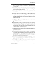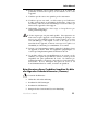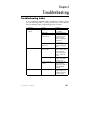
1
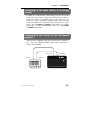
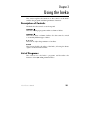
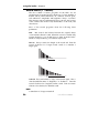
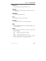
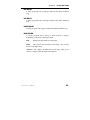
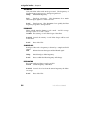
TABLE-TOP STEREO EFFECTS PROCESSOR
Reference
Manual
2001
Ineko Reference Manual
1
Ineko Manual
2
Ineko Reference Manual
Ineko Manual
Contents
Contents........................................................................................................................3
Welcome!............................................................................................6
How to Use This Manual ................................................................7
Important Safety Instructions.........................................................8
FCC Notice.......................................................................................14
Quick Start Guide .................................................................................................... 15
If you can't wait to get started:.....................................................15
Step 1: Hook it up to a mixer.........................................................15
Step 2: Try some effects..................................................................16
Play some signal into the unit...................................................16
Connections .............................................................................................................. 19
Unpacking and Inspection ............................................................19
Power ................................................................................................19
AC Power Hookup .........................................................................19
Connecting inputs and outputs ...................................................20
Connecting to an Instrument or Microphone: ...........................20
Connecting to the Effects Send & Return of a console: ............20
Connecting to the Channel Inserts of a mixing console:..........22
Connecting to the Main Inserts of a mixing console: ...............23
Connecting to the inserts on an instrument amplifier: ............23
About Audio Cables.......................................................................24
Using the Ineko........................................................................................................ 25
Description of Controls..................................................................25
List of Programs..............................................................................25
Reverb Effects (1st Column) ..........................................................26
Delay Effects (2nd Column)............................................................28
Pitch Effects (3rd Column) .............................................................30
Filter Effects (4th Column) .............................................................33
Misc. Effects (5th and 6th columns) ...............................................36
Troubleshooting ...................................................................................................... 41
Troubleshooting Index...................................................................41
Avoiding ground loop noise ........................................................42
Line Conditioners and Protectors................................................43
Care and Maintenance ...................................................................44
Ineko Reference Manual
3
Ineko Manual
Cleaning............................................................................................44
Refer All Servicing to Alesis .........................................................44
Obtaining Repair Service...............................................................44
Specifications ...................................................................................46
Audio I/O.....................................................................................46
Audio Performance.....................................................................46
Physical ........................................................................................45
Alesis Limited Warranty ........................................................................................ 47
4
Ineko Reference Manual
Ineko Manual
Ineko Reference Manual
5
Ineko Manual
Welcome!
Thank you for making the Alesis Ineko™ a part of your studio.
Since 1984, we've been designing and building creative tools for
the audio community. We believe in our products, because
we've heard the results that creative people like you have
achieved with them. One of Alesis' goals is to make high-quality
studio equipment available to everyone, and this Reference
Manual is an important part of that. After all, there's no point in
making equipment with all kinds of capabilities if no one
explains how to use them. So, we try to write our manuals as
carefully as we build our products.
The goal of this manual is to get you the information you need as
quickly as possible, with a minimum of hassle. We hope we've
achieved that. If not, please drop us an email and give us your
suggestions on how we could improve future editions of this
manual.
We hope your investment will bring you many years of creative
enjoyment and help you achieve your goals.
Sincerely,
The people of Alesis
6
Ineko Reference Manual
Ineko Manual
How to Use This Manual
This manual is divided into the following sections describing the
various functions and applications of the Ineko. While it's a
good idea to read through the entire manual once carefully,
users who are already familiar with studio equipment can use
the table of contents to look up specific functions.
Chapter 1: Quick Start. If you're already familiar with
recording, this will get you started using the Ineko right away.
It's a short guide to the essential elements of connections and
operation.
Chapter 2: Connections. This section gives detailed instructions
for connecting the Ineko to a variety of typical audio systems.
Chapter 3: Basics of Effects. This section explains what an
effects processor does and explains the function of each of the
controls.
Chapter 4: Description of Programs. This chapter lists each of
the programs and gives a description of their parameters.
Chapter 5: Troubleshooting. Refer to this chapter if you
experience any problems while using the Ineko.
Helpful tips and advice are highlighted in a shaded box like this.
The names of specific controls or connectors on the Ineko are
printed in a special font, i.e., the BYPASS button.
✪
When something important appears in the manual, an icon
(like the one on the left) will appear in the left margin. This
symbol indicates that this information is vital when operating
the Ineko.
Ineko Reference Manual
7
Ineko Manual
Important Safety Instructions
Safety symbols used in this product:
This symbol alerts the user that there are important
operating and maintenance instructions in the literature
accompanying this unit.
This symbol warns the user of un-insulated voltage within
the unit that can cause dangerous electric shocks.
This symbol warns the user that output connectors contain
voltages that can cause dangerous electrical shock.
Please follow these precautions when using this
product:
1. Read these instructions.
2.
Keep these instructions.
3.
Heed all warnings.
4.
Follow all instructions.
5.
Do not use this apparatus near water.
6.
Clean only with a damp cloth. Do not spray any liquid cleaner
onto the faceplate, as this may damage the front panel controls
or cause a dangerous condition.
7.
Install in accordance with the manufacturer's instructions.
8.
Do not install near any heat sources such as radiators, heat
registers, stoves, or other apparatus (including amplifiers) that
produce heat.
9. Do not defeat the safety purpose of the polarized or groundingtype plug. A polarized plug has two blades with one wider than
the other. A grounding-type plug has two blades and a third
grounding prong. The wide blade or the third prong are
8
Ineko Reference Manual
Ineko Manual
provided for your safety. When the provided plug does not fit
into your outlet, consult an electrician for replacement of the
obsolete outlet.
10. Protect the power cord from being walked on or pinched,
particularly at plugs, convenience receptacles, and the point
where they exit from the apparatus.
11. Use only attachments or accessories specified by the
manufacturer.
12. Use only with a cart, stand, bracket, or table designed for use
with professional audio or music equipment. In any installation,
make sure that injury or damage will not result from cables
pulling on the apparatus and its mounting. If a cart is used, use
caution when moving the cart/apparatus combination to avoid
injury from tip-over.
13. Unplug this apparatus during lightning storms or when unused
for long periods of time.
14. Refer all servicing to qualified service personnel. Servicing
is required when the apparatus has been damaged in any way,
such as when the power-supply cord or plug is damaged, liquid
has been spilled or objects have fallen into the apparatus, the
apparatus has been exposed to rain or moisture, does not
operate normally, or has been dropped.
15. This unit produces heat when operated normally. Operate in a
well-ventilated area with at least six inches of clearance from
peripheral equipment.
16. This product, in combination with an amplifier and headphones
or speakers, may be capable of producing sound levels that
could cause permanent hearing loss. Do not operate for a long
period of time at a high volume level or at a level that is
uncomfortable. If you experience any hearing loss or ringing in
the ears, you should consult an audiologist.
17. Do not expose the apparatus to dripping or splashing. Do not
place objects filled with liquids (flower vases, softdrink cans,
coffee cups) on the apparatus.
18. WARNING: To reduce the risk of fire or electric shock, do not
expose this apparatus to rain or moisture.
Ineko Reference Manual
9
Ineko Manual
Instructions de Sécurité Importantes (French)
Symboles utilisés dans ce produit
Ce symbole alèrte l’utilisateur qu’il existe des instructions de
fonctionnement et de maintenance dans la documentation jointe avec
ce produit.
Ce symbole avertit l’utilisateur de la présence d’une tension
non isolée à l’intérieur de l’appareil pouvant engendrer des chocs
électriques.
Ce symbole prévient l'utilisateur de la présence de tensions
sur les
raccordements de sorties, représentant un risque
d'électrocution.
Veuillez suivre ces précautions lors de l’utilisation de l’appareil:
1. Lisez ces instructions.
2.
Gardez ces instructions.
3.
Tenez compte de tous les avertissements.
4.
Suivez toutes les instructions.
5.
N’utilisez pas cet allareil à proximité de l’eau.
6.
Ne nettoyez qu’avec un chiffon humide. Il est potentiellement
dangereux d'utiliser des pulvérisateurs ou nettoyants liquides
sur cet appareil.
7.
Installez selon les recommandations du constructeur.
8.
Ne pas installer à proximilé de sources de chaleur comme
radiateurs, cuisinière ou autre appareils (don’t les
amplificateurs) produisant de la chaleur.
9. Ne pas enlever la prise de terre du cordon secteur. Une prise
murale avec terre deux broches et une troisièrme reliée à la terre.
Cette dernière est présente pour votre sécurité. Si le cordon
secteur ne rentre pas dans la prise de courant, demandez à un
électricien qualifié de remplacer la prise.
10
Ineko Reference Manual
Ineko Manual
10. Evitez de marcher sur le cordon secteur ou de le pincer, en
particulier au niveau de la prise, et aux endroits où il sor de
l’appareil.
11. N’utilisez que des accessoires spécifiés par le constructeur.
12. N’utilisez qu’avec un stand, ou table conçus pour l’utilisation
d’audio professionnel ou instruments de musique. Dans toute
installation, veillez de ne rien endommager à cause de câbles qui
tirent sur des appareils et leur support.
13. Débranchez l’appareil lors d’un orage ou lorsqu’il n’est pas
utilisé pendant longtemps.
14. Faites réparer par un personnel qualifié. Une réparation est
nécessaire lorsque l’appareil a été endommagé de quelque sorte
que ce soit, par exemple losrque le cordon secteur ou la prise
sont endommagés, si du liquide a coulé ou des objets se sont
introduits dans l’appareil, si celui-ci a été exposé à la pluie ou à
l’humidité, ne fonctionne pas normalement ou est tombé.
15. Puisque son fonctionement normale génère de la chaleur, placez
cet appareil au moins 15cm. des équipments péripheriques et
assurez que l’emplacement permet la circulation de l’air.
16. Ce produit, utilisé avec un amplificateur et un casque ou des
enceintes, est capable de produite des niveaux sonores pouvant
engendrer une perte permanente de l’ouïe. Ne l’utilisez pas
pendant longtemps à un niveau sonore élevé ou à un niveau non
confortable. Si vous remarquez une perte de l’ouïe ou un
bourdonnement dans les oreilles, consultez un spécialiste.
Beim Benutzen dieses Produktes beachten Sie bitte
die folgenden Sicherheitshinweise: (German)
1. Lesen Sie die Hinweise.
2.
Halten Sie sich an die Anleitung.
3.
Beachten Sie alle Warnungen.
4.
Beachten Sie alle Hinweise.
5.
Bringen Sie das Gerät nie mit Wasser in Berührung.
Ineko Reference Manual
11
Ineko Manual
6.
Verwenden Sie zur Reinigung nur ein weiches Tuch. Verwenden
Sie keine flüssigen Reinigungsmittel. Dies kann gefährliche
Folgen haben.
7.
Halten Sie sich beim Aufbau des Gerätes an die Angaben des
Herstellers.
8.
Stellen Sie das Gerät nich in der Nähe von Heizkörpern,
Heizungsklappen oder anderen Wärmequellen (einschließlich
Verstärkern) auf.
9.
Verlegen Sie das Netzkabel des Gerätes niemals so, daß man
darüber stolpern kann oder daß es gequetscht wird.
10. Benutzen Sie nur das vom Hersteller empfohlene Zubehör.
11. Verwenden Sie ausschließlich Wagen, Ständer, oder Tische, die
speziell für professionelle Audio- und Musikinstrumente
geeignet sind. Achten Sie immer darauf, daß die jeweiligen
Geräte sicher installiert sind, um Schäden und Verletzungen zu
vermeiden. Wenn Sie einen Rollwagen benutzen, achten Sie
darauf, das dieser nicht umkippt, um Verletzungen
auszuschließen.
12. Ziehen Sie während eines Gewitters oder wenn Sie das Gerät
über einen längeren Zeitraum nicht benutzen den Netzstecher
aus der Steckdose.
13. Die Wartung sollte nur durch qualifiziertes Fachpersonal
erfolgen. Die Wartung wird notwendig, wenn das Gerät
beschädigt wurde oder aber das Stromkabel oder der Stecker,
Gegenstände oder Flüssigkeit in das Gerät gelangt sind, das
Gerät dem Regen oder Feuchtigkeit ausgesetzt war und deshalb
nicht mehr normal arbeitet oder heruntergefallen ist.
14. Dieses Gerät produziert auch im normalen Betrieb Wärme.
Achten Sie deshalb auf ausreichende Lüftung mit mindestens 15
cm Abstand von anderen Geräten.
15. Dieses Produkt kann in Verbindung mit einem Verstärker und
Kopfhörern oder Lautsprechern Lautstärkepegel erzeugen, die
anhaltende Gehörschäden verursachen. Betreiben Sie es nicht
über längere Zeit mit hoher Lautstärke oder einem Pegel, der
Ihnen unangenehm is. Wenn Sie ein Nachlassen des Gehörs
oder ein Klingeln in den Ohren feststellen, sollten Sie einen
Ohrenarzt aufsuchen.
12
Ineko Reference Manual
Ineko Manual
CE Declaration of Conformity
See the Internet site:
www.alesis.com
Ineko Reference Manual
13
Ineko Manual
Instructions to the User (FCC Notice)
This equipment has been tested and found to comply with the
limits for a class B digital device, pursuant to Part 15 of the FCC
Rules. These limits are designed to provide reasonable
protection against harmful interference in a residential
installation. This equipment generates, uses, and can radiate
radio frequency energy and, if not installed and used in
accordance with the instructions, may cause harmful
interference to radio communications. However, there is no
guarantee that interference will not occur in a particular
installation. If this equipment does cause harmful interference to
radio or television reception, which can be determined by
turning the equipment off and on, the user is encouraged to try
and correct the interference by one or more of the following
measures:
1.
Reorient or relocate the receiving antenna.
2.
Increase the separation between the equipment and receiver.
3.
Connect the equipment into an outlet on a circuit different
from that to which the receiver is connected.
4.
Consult the dealer or an experienced radio/TV technician
for help.
This equipment has been verified to comply with the limits for a
class B computing device, pursuant to FCC Rules. In order to
maintain compliance with FCC regulations, shielded cables must
be used with this equipment. Operation with non-approved
equipment or unshielded cables is likely to result in interference
to radio and TV reception. The user is cautioned that changes
and modifications made to the equipment without the approval
of manufacturer could void the user’s authority to operate this
equipment.
14
Ineko Reference Manual
Chapter 1
Quick Start Guide
If you can't wait to get started:
The Alesis Ineko™ is a unique product, but its basic hookup and
operation is similar to other effects processors in most respects.
If you're experienced with signal processors, this chapter is a
"shorthand" guide for those who want to start using the Ineko
right away. If you have questions about any of the features,
don’t worry – later chapters will unveil the mysteries of the
Ineko's special features.
✪
If you're new to signal processing, start with the more detailed
instructions for hookup and operation starting in the next
chapter.
Step 1: Hook it up to a mixer
1.
Pull the Ineko out of the package.
2.
Plug the P O W E R jack on the back of the Ineko into a
grounded AC power source with the supplied power
adapter.
3.
Using a pair of 1/4” cables, plug the insert sends of the
mixer to the left and right INPUTS on the back of the Ineko.
4.
Connect the Ineko’s OUTPUTS to the effects return of the
mixer.
5.
Adjust the INPUT LEVEL knob on the back of the Ineko until
the red INPUT light does not light when signal is played into
the unit. Turn the control counter-clockwise to increase the
level.
For more information on connecting the Ineko, see
chapter 2:
Connections.
Ineko Reference Manual
15
quick start guide • chapter 1
Step 2: Try some effects
Play some signal into the unit
While learning the unit, it is helpful to play a CD or a multi-track
source into the effects processor. Choose a song or part that
doesn’t change much, so that you can take your time
experimenting with the different features.
1.
Turn the INPUT LEVEL all the way down so that you don’t
distort the unit.
2.
Begin to play your source material. Turn the INPUT knob
clockwise until the red INPUT light comes on, then back
down a bit.
3.
Use the PROGRAM
the Ineko.
4.
Turn the A, B and C knobs to adjust the program.
5.
Press the BYPASS button to hear your signal without the
effect. Press it again to return to the effected signal.
and
buttons to change programs on
If you aren’t hearing any effect, check your connections or try
another program. Some programs are easier to hear than others.
16
Ineko Reference Manual
chapter 1 • quick start guide
Ineko Reference Manual
17
quick start guide • chapter 1
18
Ineko Reference Manual
Chapter 2
Connections
Unpacking and Inspection
Your Ineko was packed carefully at the factory. The shipping
carton was designed to protect the unit during shipping. Please
retain this container in the highly unlikely event that you need to
return the Ineko for servicing.
The shipping carton should contain the following items:
•
Ineko with the same serial number as shown on shipping
carton
•
P3 Power Adapter
•
This instruction manual
Power
AC Power Hookup
Plug the female end of the power adapter into the Ineko’s 9V~
POWER INPUT socket and the male (plug) end into a good quality
AC power outlet.
Tip: It’s good practice to not plug in the Ineko until all other audio
cables are hooked up as well. Make sure your amplifier or
powered speakers are switched off when turning the Ineko on or
off to avoid damage.
The Ineko works with the AC line voltage listed on the P3
adapter that came with the unit. To use the Ineko with a
different voltage, contact your Alesis dealer for a compatible P3
adapter.
Ineko Reference Manual
19
connections • chapter 2
Connecting inputs and outputs
✪
When connecting audio cables and/or turning power on and
off, make sure that all devices in your system are turned off
and the volume controls are turned down.
Connecting to an Instrument or Microphone:
The Ineko’s INPUT LEVEL knob has been calibrated to accept
“instrument level” signals such as a microphone or guitar input.
To use the Ineko this way, simply plug the guitar or microphone
into the Ineko’s Input and connect the output to an amplifier,
mixer or recorder. When using the Ineko with a Microphone,
you may need an XLR to 1/4” adapter (not included).
Connecting to the Effects Send and Return of a
mixing console:
Most mixing consoles have post-fader effects send and return
jacks on their rear panels. This is usually the best choice for
connecting the Ineko, as you will be able to use an effect on
several sources at once.
Effects Send
Ineko In
Effects Return
Ineko Out
When you connect the Ineko this way, you may hear an odd
phasing sound on some of the reverb and delay programs. To
prevent this, always set the MIX parameter (usually the A knob)
fully clockwise. You can then control the balance between the
20
Ineko Reference Manual
chapter 2 • connections
direct and effect signal with the effects return level control on
your mixer.
Ineko Reference Manual
21
connections • chapter 2
Connecting to the Channel Inserts of a mixing
console:
Most mixing consoles have a jack near the mic and line inputs
labeled "Insert". This is typically a TRS jack with the send and
return on the same jack. To use the Ineko as a channel insert, you
will need an insert cable (not included).
Insert Send:
To Ineko Input
Ring:
Insert Return
T
Tip:
Insert Send
Sleeve:
Insert Ground
Insert Return:
From Ineko
Output
This cable splits the TRS insert jack into two unbalanced mono
connectors. Usually, the tip is connected to the INPUT of the
effects processor and the ring is connected to the OUTPUT of the
effects processor. However, this may be reversed on some
mixing consoles. Check your mixer’s Reference Manual to be
sure or just try it both ways – this won’t damage the Ineko. You
may need to raise the mixer’s input trim if the signal coming
back from the Ineko is too low.
Mixer Insert
Ineko In
22
Ineko Out
Ineko Reference Manual
chapter 2 • connections
Connecting to the Main Inserts of a mixing
console:
In addition to channel inserts, most mixing consoles have main
insert jacks near the main outputs. You can use insert cables to
connect the Ineko to the main L/R bus the same way you
connect it to a pair of channels. Simply connect one insert cable
to the left main insert of the mixer, and connect the two mono
jacks to the left INPUT and OUTPUT of the Ineko. Use another
insert cable to connect the right main insert to the right INPUT
and OUTPUT of the Ineko.
Connecting to the inserts on an instrument
amplifier:
Guitar and bass amplifiers often have insert points for effects as
well. These are typically labeled "effects send and return" or
"insert send and return".
Effects Send
Ineko In
Effects Return
Ineko Out
J
Ineko Reference Manual
23
connections • chapter 2
About Audio Cables
The connections between the Ineko and your studio are your
music’s lifeline, so use only high quality cables. These should be
low-capacitance shielded cables with a stranded (not solid)
internal conductor and a low-resistance shield. Although quality
cables cost more, they do make a difference.
Route cables to the Ineko correctly by observing the following
precautions:
•
Do not bundle audio cables with AC power cords.
•
Avoid running audio cables near sources of electromagnetic
interference such as transformers, monitors, computers, etc.
•
Do not place cables where they can be stepped on. Stepping
on a cable may not cause immediate damage, but it can
compress the insulation between the center conductor and
shield (degrading performance) or reduce the cable’s
reliability.
•
Avoid twisting the cable or having it make sharp, right angle
turns.
•
Never unplug a cable by pulling on the wire itself. Always
unplug by firmly grasping the body of the plug and pulling
directly outward.
And most importantly, keep connectors clean. Every few months,
unplug them and wipe off oxidation with a clean cloth soaked in
alcohol or contact cleaner. Insert the plugs in the jacks a few
times, to clean the internal jack contacts. Although Alesis does
not endorse any specific product, chemicals such as Tweek and
Cramolin, when applied to electrical connectors, are claimed to
improve the electrical contact between connectors.
24
Ineko Reference Manual
Chapter 3
Using the Ineko
This section explains the functions of the controls on the Ineko
and lists the programs and their parameters’ functions.
Description of Controls
The Ineko has five controls on its front panel:
PROGRAM
This button changes programs within a column of effects.
PROGRAM
This button selects a column of effects. Use this control to switch
to an entirely different type of effect.
A, B
and C
These knobs adjust the parameters of an effect.
BYPASS
This button disables the effect of the Ineko, allowing the direct
signal to be heard without Effect.
List of Programs
This section lists the Ineko’s programs and describes the
functions of the A, B and C parameter knobs.
Ineko Reference Manual
25
using the ineko • chapter 3
Reverb Effects (1st Column)
The first column of effects programs in the Ineko are all
reverberation programs. Reverb is made up of a large number of
distinct echoes, called reflections. In a natural acoustic space,
each reflection’s amplitude and brightness decays over time.
This decaying action is influenced by the room size, the location
of the sound source in the room, the hardness of the walls, and
other factors.
Most of the reverb programs share the following three
parameters:
MIX
Mix controls the balance between the original, direct
sound and the effected sound. When this control is turned fully
counter-clockwise, you should hear no effect from the Ineko.
When it is fully clockwise, you will hear only reverb.
DECAY Decay controls the length of the reverb tail. Turn the
control clockwise for a longer reverb sound or to simulate a
larger space.
Short
r Decay Time
Long Decay T
Time
COLOR The tonal balance or “EQ” of the reverb signal. This is
often described in terms of “brightness” or “darkness”. Turn the
control clockwise for a brighter, livelier sound. Turn it counterclockwise for a darker, less defined sound.
HALL
A simulation of a large concert hall.
26
Ineko Reference Manual
chapter 3 • using the ineko
VOCAL HALL
A smaller, brighter concert hall designed for vocals.
VOC PLATE
Emulation of a classic plate reverb, transparent and smooth, also
good for vocals.
DRUM ROOM
Room reverb optimized for drums.
SPACE
A large space for sounds to swim around in.
TRASH CAN
A trashy metallic reverb. Try it on drums and guitars.
GATED
This reverb’s signal abruptly cuts in and which abruptly cuts off,
good for rock drums.
REVERSE
This reverb has a reversed decay envelope – fading in, then
cutting off abruptly.
MIX
Balance between direct/reverb signal.
TIME
Length of time until the effect cuts off.
RATE
This adjusts the fade-in slope, or “attack” of the effect.
Turn the control clockwise for a more gradual fade-in.
Ineko Reference Manual
27
using the ineko • chapter 3
Delay Effects (2nd Column)
The second column of effects programs in the Ineko are delay
programs. Delay provides a discrete repetition, or echo of the
input signal. A portion of the delayed signal is fed back into the
input to produce additional echoes of the original signal.
Most of the programs in this column share the following three
parameters:
MIX
Mix controls the balance between the original, direct
sound and the effected sound. When this control is turned fully
counter-clockwise, you should hear no effect from the Ineko.
When it is fully clockwise, you will hear only the delayed signal.
DELAY This control specifies the amount of time that the input
sound is delayed.
FDBK Feedback adjusts the amount of the delayed signal
which is fed back into the input. This effectively controls how
many times you will hear the input signal repeat. When
Feedback is set fully counter-clockwise, you will only hear one
repeat of the input signal. When it is fully clockwise, the high
feedback level can cause self-oscillation.
DELAY
A simple mono delay.
ST DELAY
A stereo delay program.
RUNAWAY
A mono delay where the Mix control has been placed in front of
the delay loop. Careful manipulation of the Mix knob will let
you create complex looping phrases. Or just crank up the Mix
for out-of-control fun.
LPF DELAY
A delay program which passes the delayed signal through a
low-pass filter.
28
Ineko Reference Manual
chapter 3 • using the ineko
HPF DELAY
A delay program with a high-pass filter in the delay feedback
loop.
BPF DELAY
A delay program with a band-pass filter in the delay feedback
loop.
PHASE DELAY
A delay program with a phasor effect in the delay feedback loop.
DYN REVERB
A reverb program whose decay is made shorter or longer,
depending on the level of the input signal.
MIX
Balance between direct/reverb signal
SENS
This controls the sensitivity of the effect – how closely
it follows the input level.
-DECAY+ This adjusts whether the reverb decay time grows
shorter or longer when the input level increases.
Ineko Reference Manual
29
using the ineko • chapter 3
Pitch Effects (3rd Column)
The third column of programs are Pitch effects. The Pitch effects
alter the pitch of a signal in various ways to produce “layered”
timbres that are more complex than the original signal.
Many of these effects make use of a Low Frequency Oscillator LFO – to modulate the signal. The effect of the LFO modulation
is heard as a sound characteristic rising and falling at a constant,
cyclical rate.
PHASE 1
A classic 4-stage phasor effect with feedback.
FDBK
Adjusts the amount of feedback, making the effect
more pronounced.
WIDTH Controls how far the LFO sweeps.
RATE
Rate of the LFO.
PHASE 2
Deeper, 8-stage phasor effect.
PITCH Adjusts the center frequency from which the LFO
modulates up and down. This effectively sets the frequency
range and character of the effect.
WIDTH Controls how far the LFO sweeps.
RATE
Rate of the LFO.
FLANGER
Classic sweeping tape flange effect.
PITCH Adjusts the center frequency from which the LFO
modulates up and down. This effectively sets the frequency
range and character of the effect.
WIDTH Controls how far the LFO sweeps.
RATE
30
Rate of the LFO.
Ineko Reference Manual
chapter 3 • using the ineko
INV FLANGER
Flanger effect with the feedback signal inverted for a hollow,
metallic sound.
PITCH Adjusts the center frequency from which the LFO
modulates up and down. This effectively sets the frequency
range and character of the effect.
WIDTH Controls how far the LFO sweeps.
RATE
Rate of the LFO.
TRANSPOSE
Dual pitch shifter which transposes the signal harmonically.
MIX
Balance between direct and pitch-shifted signal.
PITCH L Amount of pitch shift (+/-) applied to Left signal.
PITCH R Amount of pitch shift (+/-) applied to Right signal.
ST DETUNE
Dual pitch detune effect.
MIX
Balance between direct and pitch-shifted signal.
PITCH L Amount of detune (+/-) applied to Left signal.
PITCH R Amount of detune (+/-) applied to Right signal.
CHORUS
Rich 6 –voice chorus effect.
MIX
Balance of direct and effected signals.
PITCH Adjusts the center frequency from which the LFO
modulates up and down. This effectively sets the frequency
range and character of the effect.
WIDTH Controls how far the LFO sweeps.
Ineko Reference Manual
31
using the ineko • chapter 3
VIBRATO
LFO controlled pitch shift.
DEPTH How far the pitch is shifted by the LFO.
SHAPE Shape of the LFO wave. Constantly variable from a
smooth sine to chaotic sample-and-hold.
RATE
32
Rate of the LFO.
Ineko Reference Manual
chapter 3 • using the ineko
Filter Effects (4th Column)
The fourth column of effects on the Ineko has a series of filter
effects. These effects change the frequency response of the input
by boosting or cutting parts of the signal.
BAND LIMIT
Limits the high and low frequency range of the input. Good for
emulating telephones, radio and other low-fidelity sound
sources.
FREQ
Adjusts the center frequency of the effect – mid point
between the high and low frequency cut-offs.
WIDTH The bandwidth of the filter. This determines the
distance between the highest and lowest frequencies which will
be heard.
NOISE
Adds noise to the signal. Useful for “Lo-Fi” effects.
LP BP HP
A selectable low-pass, band-pass or hi-pass filter with resonance.
FREQ
Cut-off frequency of the filter. This sets which
frequencies are boosted and which are cut by the filter.
Q
Adjusts the resonance, or shape of the filter at the cutoff frequency. Turning the knob clockwise increases the level
boost at the cutoff frequency. At high Q levels, the filter can selfoscillate.
LP-BP-HP Toggles between low-pass, band-pass and high-pass
filter modes.
LFO LP
A resonant low-pass filter who’s frequency is modulated by an
LFO.
FREQ
Initial cut-off frequency of the filter.
WIDTH Width of the filter change.
RATE Rate of the LFO.
Ineko Reference Manual
33
using the ineko • chapter 3
AUTOWAH
Wah-wah filter effect with envelope control. The frequency of
the filter changes in response to the input signal level.
FREQ
Initial filter frequency.
ENV
Envelope sensitivity. This determines how much
effect the input signal has on the wah-wah.
RATE
Envelope rate. This determines how quickly the filter
frequency responds to the input level.
FORMANTS
Filters which simulate human vocal sounds. An LFO sweeps
through a series of “vowel” sounds.
VOWEL The starting “vowel” filter shape of the effect.
RANGE Controls how many “vowel” filter shapes will be used
in the effect.
RATE
Rate of the LFO.
SAMPLED BP
Band-pass filter who’s frequency is driven by a sample-and hold
circuit.
MIX
Balance between the input and the filtered signal.
FREQ
Initial band-pass filter frequency.
RATE
Rate at which the filter frequency will change.
RESONATOR
Resonant band-pass filters swept by an LFO.
PITCH Center frequency of the filters.
RANGE Controls how far from the center frequency the filters
are swept.
RATE
34
Rate of the LFO.
Ineko Reference Manual
chapter 3 • using the ineko
AUTOPHAZ
An envelope controlled phasor effect. The sweep of the phasor
tracks the input signal level.
SENS
Sensitivity of the envelope. This determines how
closely the phasor follows the input level.
FDBK
Amount of feedback. Turn clockwise to make the
effect more pronounced.
RATE
Rate of the envelope. This determines how quickly the
phasor sweeps.
Ineko Reference Manual
35
using the ineko • chapter 3
Misc. Effects (5th and 6th columns)
The last two columns of effects on the Ineko are a selection of
miscellaneous effects.
RING MOD
Ring modulator effect with envelope follower.
DEPTH Amount of ring modulation.
ENV
Input envelope follower amount. Turn this knob
clockwise to increase the effect that the input level has on the
modulator frequency.
FREQ
Frequency of the modulating signal.
DECIMATOR
Reduces the digital resolution of the signal to create unique lo-fi
distortion.
DECIM Amount of decimation.
RING
Turn clockwise to increase the aliasing artifacts.
DAMP Filter to decrease high frequency distortion and
aliasing artifacts.
FREQ SHIFT
Shifts frequency without preserving harmonics.
MIX
Balance of Frequency shifted signal and input.
FREQ
Adjusts how far frequency is shifted from original.
WARP
Stereo modulation amount.
RMS LIMITER
A faithful emulation of a classic optical limiter.
DRIVE Amount of gain reduction.
RATE
Attack and release envelope rate. Turn clockwise for
slower envelope.
OUTPUT Output volume.
36
Ineko Reference Manual
chapter 3 • using the ineko
VOCO-BEND
40-band vocoder with adjustable formant frequencies.
SHIFT
Shifts the frequencies of the output formant filters.
SIBIL
Amount of sibilant boost for intelligibility.
IN MIX
Mix between input signal and vocoder output.
VOCODER
40-band vocoder effect for robotic vocals.
PITCH Pitch of the carrier wave.
SIBIL
Amount of sibilant boost for intelligibility.
IN MIX
Mix between input signal and vocoder output.
GRINDER
Filtered, multi-band distortion. Works best with dynamic
material.
THRES Threshold of the distortion.
RES
Filter resonance.
FREQ
Band-pass frequencies.
SUB BASS
Sub-harmonic synthesizer. Adds ultra-low bass to the signal.
SUB
Sub-harmonic (sub-bass) level.
DRIVE Multi-band limiter threshold. This adjusts the “feel”
of the bass – turn counter-clockwise for a more dynamic sound,
clockwise for longer sustain..
LO CUT Adjusts frequency of steep high-pass filter. At high
volumes, the ultra-low bass frequencies produced by the SUB
BASS program have the potential to damage some speakers.
Turn knob clockwise to reduce the low frequencies.
Ineko Reference Manual
37
using the ineko • chapter 3
AUTOPAN
Automated stereo panning effect.
CENTER Pan location of the mono summed input.
WIDTH Width of the panning effect.
RATE
Rate at which the signal is panned.
TREMOLO
Mono tremolo (volume modulation) effect.
DEPTH Amount of volume change.
SHAPE
Shape of the tremolo wave, from sine to square.
RATE
Rate at which the volume will be varied.
REC NOISE
Vinyl record emulator.
DUST
Amount of dust on the record.
TICKS
Amount of scratches on the record.
SKIP
Turn the control in either direction to simulate a
record skipping.
TAPE SAT
Simulates the effects of analog tape saturation.
DRIVE Amount of tape saturation.
38
NOISE
Amount of simulated tape hiss.
BUMP
Amount of bass boost.
Ineko Reference Manual
chapter 3 • using the ineko
FUZZ
Big and furry, analog-style distortion.
DRIVE Amount of distortion.
LOW
Low frequency boost.
HIGH
High frequency boost.
G GARAGE
Multi-effect with compression, stereo detune, and trashy reverb.
Try it on guitar or drums.
COMP Amount of compression.
DETUNE Depth of detune effect.
REVERB Reverb level.
PITCH / REV
A reverb’s decay is looped through a pitch shifter with spacey
and supernatural results. Try it on vocals or lead instruments.
MIX
Balance between the direct and effected signal.
DECAY Reverb decay time.
PITCH
Amount of pitch shift up or down.
VIBROWOBL
Unsynchronized Vibrato and tremolo effects.
VIBRO Rate of the Vibrato effect.
TREMO Rate of the Tremolo effect.
DEPTH Depth of the Vibrato and Tremolo effects.
amounts may cause sea-sickness!
Ineko Reference Manual
Large
39
using the ineko • chapter 3
40
Ineko Reference Manual
Chapter 4
Troubleshooting
Troubleshooting Index
If you experience problems while operating your Ineko, please
use the following table to locate possible causes and solutions
before contacting Alesis Product Support for assistance.
Symptom
No audio from
outputs
Cause
No input audio
Bad cables
Destination is
turned down
Power is not
connected
Buzz from outputs
Cables are crossing a
power cable
Bad cables
Problem with the
source
AC hum
Ineko Reference Manual
Ground loop
Solution
Test with a known
good input.
Replace the cables.
Check the
connections and
the level of the
mixer or amp that
the Ineko is
connected to.
Verify that power
supply is plugged
in.
Make sure that the
Ineko and its audio
cables are kept
away from power
cables, and wall
warts.
Replace the cable
with a new, highquality cable.
Try removing the
Ineko from the
signal path, and see
if the problem
remains.
Place all equipment
in the studio on a
common ground
(see next page)
41
Avoiding ground loop noise
In today’s studio, there are many opportunities for ground loop
problems to occur. These show up as hums, buzzes or sometimes
radio reception and can occur if a piece of equipment "sees" two
or more different paths to ground. While there are methods to
virtually eliminate ground loops and stray radio frequency
interference, most of the professional methods are expensive and
involve installing a separate power source just for the sound
system. Alternatively, here are some helpful hints that
professional studio installers use to keep those stray hums and
buzzes to a minimum.
¾
KEEP ALL ELECTRONICS OF THE SOUND SYSTEM ON THE
SAME AC ELECTRICAL CIRCUIT.
Most stray hums and buzzes happen as a result of different parts
of the sound system being plugged into outlets of different AC
circuits. If any noise generating devices such as air conditioners,
refrigerators, neon lights, etc., are already plugged into one of
these circuits, you then have a perfect condition for stray buzzes.
Since most electronic devices of a sound system don’t require a
lot of current (except for power amplifiers), it’s usually safe to
run a multi-outlet box or two from a SINGLE wall outlet and
plug in all of the components of your system there.
¾
KEEP AUDIO WIRING AS FAR AWAY FROM AC WIRING
AS POSSIBLE.
Many hums come from audio cabling being too near AC wiring.
If a hum occurs, try moving the audio wiring around to see if the
hum ceases or diminishes. If it’s not possible to separate the
audio and AC wiring in some instances, make sure that the
audio wires don’t run parallel to any AC wire (they should only
cross at right angles, if possible).
¾
TO ELIMINATE HUM IF THE ABOVE HAS FAILED:
A) Disconnect the power from all outboard devices and tape
machines except for the Ineko, the mixer and control room
monitor power amp.
B) Plug in each tape machine and outboard effects device one at
a time. If possible, flip the polarity of the plug of each device
42
Ineko Reference Manual
(turn it around in the socket) until the quietest position is
found.
C) Make sure that all of the audio cables are in good working
order. Cables with a detached ground wire will cause a very
loud hum!!
D) Keep all cables as short as possible, especially in unbalanced
circuits.
If the basic experiments don’t uncover the source of the problem,
consult your dealer or technician trained in proper studio
grounding techniques. In some cases, a "star grounding" scheme
must be used, with the mixer at the center of the star providing
the shield ground on telescoping shields, which do NOT connect
to the chassis ground of other equipment in the system.
Line Conditioners and Protectors
Although the Ineko is designed to tolerate typical voltage
variations, in today’s world the voltage coming from the AC line
may contain spikes or transients. These can cause audible
noises, and they can stress your gear and, over time, possibly
cause a failure. There are three main ways to protect against
this, listed in ascending order of cost and complexity:
•
Line spike/surge protectors. Relatively inexpensive, these
are designed to protect against strong surges and spikes,
acting somewhat like fuses in that they need to be replaced if
they’ve been hit by an extremely strong spike.
•
Line filters. These generally combine spike/surge protection
with filters that remove some line noise (dimmer hash,
transients from other appliances, etc.). A good example is
the Isobar™ series from Tripp Lite.
•
Uninterruptible power supply (UPS). This is the most
sophisticated option. A UPS provides power even if the AC
power line fails completely. Intended for computer
applications, a UPS allows you to complete an orderly
shutdown of a computer system in the event of a power
outage. In addition, the isolation it provides from the power
line minimizes all forms of interference—spikes, noise, etc.
Ineko Reference Manual
43
Care and Maintenance
Cleaning
Disconnect the AC cord, then use a damp cloth to clean the
Ineko’s metal and plastic surfaces. For heavy dirt, use a nonabrasive household cleaner such as Formula 409™ or
Fantastik™. DO NOT SPRAY THE CLEANER DIRECTLY
ONTO THE FRONT OF THE UNIT AS IT MAY DESTROY THE
LUBRICANTS USED IN THE SWITCHES AND CONTROLS!
Spray onto a cloth, then use cloth to clean the unit.
Refer All Servicing to Alesis
We believe that the Ineko is one of the best signal processors that
can be made using current technology, and should provide years
of trouble-free use. However, should problems occur, DO NOT
attempt to service the unit yourself unless you have training and
experience. Service on this product should be performed only
by qualified technicians. NO USER-SERVICEABLE PARTS
INSIDE.
Obtaining Repair Service
Before contacting Alesis, check over all your connections, and
make sure you’ve read the manual.
Customers in the USA and Canada:
If the problem persists, contact Alesis and request the Product
Support department. Make sure you have the unit’s serial
number with you. Talk the problem over with one of our
technicians; if necessary, you will be given a return order (RO)
number and instructions on how to return the unit. All units
must be shipped prepaid and COD shipments will not be
accepted.
For prompt service, indicate the RO number on the shipping
label. Units without an RO will not be accepted. If you do not
have the original packing, ship the unit in a sturdy carton, with
shock-absorbing materials such as Styrofoam pellets (the kind
without CFCs, please) or "bubble-pack" surrounding the unit.
Shipping damage caused by inadequate packing is not covered
by the Alesis warranty.
Tape a note to the top of the unit describing the problem, include
your name and a phone number where Alesis can contact you if
necessary, as well as instructions on where you want the product
44
Ineko Reference Manual
returned. Alesis will pay for standard one-way shipping back to
you on any repair covered under the terms of this warranty.
Next day service is available for a surcharge. Field repairs are
not authorized during the warranty period, and repair attempts
by unqualified personnel may invalidate the warranty.
Customers outside the USA and Canada:
Contact your local Alesis distributor for any warranty assistance.
The Alesis Limited Warranty applies only to products sold to
users in the USA and Canada. Customers outside of the USA
and Canada are not covered by this Limited Warranty and may
or may not be covered by an independent distributor warranty
in the country of sale. Do not return products to the factory
unless you have been given specific instructions to do so.
Internet Address:
Important information and advice is available on our web site:
http://www.alesis.com
Email may be addressed to:
[email protected]
Ineko Reference Manual
45
Specifications
Subject to change without notice
Audio I/O
Input/Output Connectors:
Maximum Input Level:
Input impedance:
Maximum Output Level:
Output impedance:
1/4" mono jacks
+10dBV (7.78 Vrms)
470k Ohms
+10dBV (7.78 Vrms)
470 Ohms
Audio Performance
Dynamic Range:
THD+N @ 1kHz:
Frequency Response:
A/D-D/A Conversion:
Signal Processing:
>95dB
0.006%
20Hz -20 kHz ±0.1 dB
24 bit, 44.1 kHz
28 bit Alesis DSP
Physical
Dimensions:
Weight:
Power:
46
5.75” x 1.75” x 5.50”
(146mm x 45mm x 140mm)
13.4 oz (6.1 kg)
9V AC
Ineko Reference Manual
Alesis Limited Warranty
ALESIS STUDIO ELECTRONICS ("ALESIS") warrants
this product to be free of defects in material and workmanship
for a period of one (1) year for parts and for a period of one (1)
year for labor from the date of original retail purchase. This
warranty is enforceable only by the original retail purchaser and
cannot be transferred or assigned.
During the warranty period ALESIS shall, at its sole and
absolute option, either repair or replace free of charge any
product that proves to be defective on inspection by ALESIS or
its authorized service representative. In all cases disputes
concerning this warranty shall be resolved as prescribed by law.
To obtain warranty service, the purchaser must first call
or write ALESIS at the address and telephone number printed
below to obtain a Return Authorization Number and
instructions concerning where to return the unit for service. All
inquiries must be accompanied by a description of the problem.
All authorized returns must be sent to ALESIS or an authorized
ALESIS repair facility postage prepaid, insured and properly
packaged. Proof of purchase must be presented in the form of a
bill of sale, canceled check or some other positive proof that the
product is within the warranty period. ALESIS reserves the
right to update any unit returned for repair. ALESIS reserves
the right to change or improve design of the product at any time
without prior notice.
This warranty does not cover claims for damage due to
abuse, neglect, alteration or attempted repair by unauthorized
personnel, and is limited to failures arising during normal use
that are due to defects in material or workmanship in the
product.
THE ABOVE WARRANTIES ARE IN LIEU OF ANY
OTHER WARRANTIES OR REPRESENTATIONS WHETHER
EXPRESS OR IMPLIED OR OTHERWISE, WITH RESPECT TO
THE PRODUCT, AND SPECIFICALLY EXCLUDE ANY
IMPLIED WARRANTIES OF FITNESS FOR A PARTICULAR
PURPOSE OR MERCHANTABILITY OR OTHER IMPLIED
WARRANTIES. Some states do not allow limitations on how
long an implied warranty lasts, so the above limitation may not
apply to you.
Ineko Reference Manual
47
IN NO EVENT WILL ALESIS BE LIABLE FOR
INCIDENTAL, CONSEQUENTIAL, INDIRECT OR OTHER
DAMAGES RESULTING FROM THE BREACH OF ANY
EXPRESS OR IMPLIED WARRANTY, INCLUDING, AMONG
OTHER THINGS, DAMAGE TO PROPERTY, DAMAGE BASED
ON INCONVENIENCE OR ON LOSS OF USE OF THE
PRODUCT, AND, TO THE EXTENT PERMITTED BY LAW,
DAMAGES FOR PERSONAL INJURY. Some states do not allow
the exclusion or limitation of incidental or consequential
damages, so the above limitation or exclusion may not apply to
you.
THIS CONTRACT SHALL BE GOVERNED BY THE
INTERNAL LAWS OF THE STATE OF CALIFORNIA
WITHOUT REFERENCE TO CONFLICTS OF LAWS. This
warranty gives you specific legal rights, and you may also have
other rights required by law which vary from state to state.
This warranty only applies to products sold to
purchasers in the United States of America or Canada. The
terms of this warranty and any obligations of Alesis under this
warranty shall apply only within the country of sale. Without
limiting the foregoing, repairs under this warranty shall be made
only by a duly authorized Alesis service representative in the
country of sale. For warranty information in all other countries
please refer to your local distributor.
ALESIS Studio Electronics
Los Angeles, CA
www.alesis.com
Alesis Studio Electronics, Los Angeles, CA
© 2001 Alesis Studio Electronics, Specifications Subject To Change Without
Notice
48
Ineko Reference Manual