1
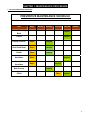
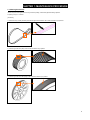
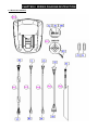
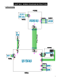
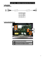
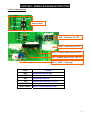
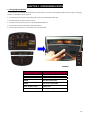
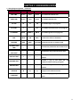
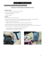
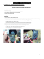
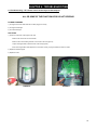
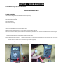
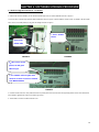
Vision Fitness U70-02 (CB68C) Service Manual
TABLE OF CONTENTS
CHAPTER 1: MAINTENANCE PROCEDURE
1.1 Preventive Maintenance Schedule…………………………………………………………..4
1.2 Cleaning the Grooves………………………………………...............................................5
CHAPTER 2: WIRING DIAGRAM INSTRUCTION
2.1 Electrical Installation…………………………………………………………………….…....6
2.2 Electrical Diagram…………………………….………………………………………….…...7
2.3
Wiring Diagram……………………………………………………………………………......8
2.4
2.5
Lower Control Board Wiring Diagram………………….………………………….………...8
Console Wiring Diagram……………………………………………………………………...9
CHAPTER 3: ENGINEERING MODE
3.1 Using Engineering Mode...............................................................................................11
CHAPTER 4: TROUBLESHOOTING
4.1 Console Error Codes………………………………………………………………………….12
4.2
4.3
4.4
4.5
Troubleshooting – No Display on the Console or the Display is Dim..………………….13
Troubleshooting – No RPM is Displayed During the Exercise………………..…….…....14
Troubleshooting – All or Some of the Function Keys Do Not Respond………….......….15
Troubleshooting – High or No Resistance…………………………………………..…...…16
4.6
4.7
4.8
Troubleshooting – Pedals Slipping…………………………………….…………..……..….17
Troubleshooting – Knocking or Creaking Noise………….……………………………...…17
Troubleshooting – Heart Rate Function Does Not Work or is Reading Incorrectly……..18
CHAPTER 5: PART REPLACEMENT GUIDE
5.1 Console Replacement.....................................................................................................19
5.2 Heart Rate Handlebar Replacement ..............................................................................20
5.3 Heart Rate Grip Replacement ........................................................................................21
5.4
5.5
5.6
5.7
Cup Holder Replacement................................................................................................22
Seat Pad Replacement...................................................................................................23
Back Pad Replacement..................................................................................................24
Seat Post Replacement..................................................................................................25
5.8
5.9
5.10
5.11
Seat Post Insert Replacement........................................................................................26
Pedal Replacement........................................................................................................27
Crank Removal…...........................................................................................................28
Shrouds Removal...........................................................................................................28
5.12 Lower Control Board Replacement ...............................................................................29
5.13 Drive Belt Replacement..................................................................................................31
2
CHAPTER 5: PART REPLACEMENT GUIDE
5.14 Idler Set Replacement....................................................................................................32
5.15 Generator Belt Replacement..........................................................................................33
5.16
5.17
5.18
5.19
Generator Replacement.................................................................................................35
Transmission Axle Set Replacement .............................................................................37
Pulley Axle Set Replacement.........................................................................................39
Rear Stabilizer Replacement......................................................................................…42
5.20 Testing the Bike......................................................................................................... …43
CHAPTER 6: SOFTWARE UPGRADE PROCEDURE
6.1 Software Upgrade Instructions…....................................................................................44
3
CHAPTER 1: MAINTENANCE PROCEDURE
1.1 Preventive Maintenance Schedule
PREVENTIVE MAINTENANCE SCHEDULE
Item
Daily
Weekly
Monthly
Quarterly Biannual
Console Mounting
Bolts
Inspect
Frame
Inspect
Display Console
Clean
Inspect
Seat Guide Rods
Clean
Lubricate
Pedals
Clean
Inspect
Handlebar
Clean
Handrail &
Handlebar
Clean
Belt Grooves
V Belt
Annual
Inspect
Inspect
Inspect
Clean
Inspect
4
CHAPTER 1: MAINTENANCE PROCEDURE
1.2 Cleaning the Grooves
If there is any dust in the grooves of the Poly-V belts and pulleys, noises will be generated during operation.
Frequency: Every 3 to 4 months.
[Procedure]:
1. Remove the Poly-V belts (450-JFG) and check the grooves of the belt for dirt or dust and clean if any is present.
2. Check the grooves in the pulley for dirt or dust and clean if any is present.
3. Check the grooves in the roller pulley for dirt or dust and clean if any is present.
5
CHAPTER 2: WIRING DIAGRAM INSTRUCTION\
2.1 Electrical Installation
6
CHAPTER 2: WIRING DIAGRAM INSTRUCTION\
2.2 Electrical Diagram
7
CHAPTER 2: WIRING DIAGRAM INSTRUCTION\
2.3 Wiring Diagram
P01- CONSOLE WIRE
2.4 Lower Control Board Diagram
J2
J3
J4
J2
7 pin terminal to the console
J3
3 pin terminal to the generator
J4
2 pin terminal to the power resistor
8
CHAPTER 2: WIRING DIAGRAM INSTRUCTION\
2.5 Console Wiring Diagram
Select switch
JQK – Quick key for S70
JQK1 – Quick key for R70
JHD – Console digital wire for S70
JAI – Console wire for S60, U/R 70
JHG1, JHG2 – Hang grip
Port
JQK
JQK1
JHD
JAI
JHG1/JHG2
Select switch
Function
Quick key cable for S70
Quick key cable for R70
Console wire for S70
Console wire for S60, U70, R70
Hand grip cable for all models
Select current model by hand
9
CHAPTER 3: ENGINEERING MODE
3.1 Using Engineering Mode
1. Press & Hold both UP and DOWN RESISTANCE keys at the same time for 3-5 second to enter Engineering Mode as shown in Figure A. The display
will show “P1 MAX TIME” as shown in Figure B.
2. To scroll through the list of options in Engineering Mode, use the UP and DOWN RESISTANCE keys.
3. Press the ENTER key to see the value of the function.
4. To change the value of the setting, use the UP and DOWN RESISTANCE keys.
5. To confirm and save the value of the setting, press the ENTER key.
6. Press and hold the START key for 3-5 seconds to return to normal operation.
FIGURE A
FIGURE B
KEY NAME
FUNCTION
UP
Select function or adjust value
DOWN
Select function or adjust value
ENTER
Enter the function item
START
Save value or quit mode
Hold “ START” key 3’s
System reset
Hold “ UP&DOWN” key 3’s Enter engineering mode
10
CHAPTER 3: ENGINEERING MODE
3.1 Using Engineering Mode – Continued
CUSTOMSETTING DEFAULT MINIMUM
MAXIMUM
DESCRIPTION
MAX TIME
99 min
5 min
99 min
Set a maximum workout time
USER TIME
60 min
5 min
99 min
Set a default workout time
DF AGE
40
10
100
Set a default age for all programs
DF LEVEL
1
1
20
Set a default resistance level for all programs
DF GENDER
MALE
FEMALE
MALE
Set a default gender for all programs
UNIT
MILE
KM
MILE
Set the unit to miles or kilometers
MACHINE
BIKE
BIKE
_
_
_
Total time the product has been used in hours.
_
_
_
Total distance the product has been used.
DISPLAY TEST
-
-
-
MACHINE TEST
_
_
_
KEYPAD TEST
_
_
_
VERSION
-
-
-
ACCUMULATED
TIME
ACCUMULATED
DISTANCE
LANGUAGE
ELLIPTICAL Set machine to bike or elliptical mode
Used by service technicians to test LED
displays
Provides a way to test heart rate and
resistance without entering a program.
Provides a way to test the keypads for
function.
Display Current software version
The native language prompts in the instruction
center
11
CHAPTER 4: TROUBLESHOOTING
4.1 Console Error Codes
Error Messages on the Console
Code
Class
0x0441
B
Description
Solution
When UCB implements a command, LCB has not
Check the console cable connection, replace the LCB.
received this command.
Power resistor is short circuited (over 4A), or the current
0x01AC
C
Check the connection of power resistor or replace power resistor
is over 3.7A for 1 second.
0x02AB
C
Machine Type Error
Set the Machine Type to the correct type of LCB
0x02B3
C
Resistance Type Error
Set the Machine Type to the correct type of LCB
0x04A0
C
The LCB has no message returned to the UCB for over
Check the console cable connections, replace the LCB / UCB as needed.
3 seconds.
0x0201
A
LCB Battery Low Voltage
Check battery recharge function or replace new battery
0x0248
B
Battery disconnection or fail.
Check the connection of battery or replace new battery
12
CHAPTER 4: TROUBLESHOOTING
4.2 Troubleshooting – No Display on the Console or the Display is Dim
NO DISPLAY ON THE CONSOLE OR THE DISPLAY IS DIM
POSSIBLE CAUSES:
1. The console is damaged or the console cable is not connected properly.
2. Poor connection to all the terminals on the control board.
3. The lower control board is damaged.
4. The generator is damaged.
SOLUTION:
1. Check the connection of the console cable at the UCB.
2. Remove the console cable from the J5 socket on the console. Pedal the machine and set your multi-meter to DC voltage and place both
terminals on pins 1 & 4 of the console cable. There should be a reading of more than 5.5VDC (Figure A).
- If voltage is more than 5.5VDC, replace the console.
- If voltage is less than 5.5VDC, or the new console does not resolve the issue, replace the console cable.
3. Open the rear shrouds then check if all the wire harnesses are connected properly to the terminals of the LCB.
4. Unplug the generator cable from the control board, pedal the machine and set your multi-meter to AC voltage and place both terminals on pins 1 &
2, pins 2 & 3, and pins 3 & 1 of the console cable to check if the voltage is variable (Figure B).
- If the voltage reading shown is variable (varies based on RPM), replace the LCB.
- If the voltage reading shown is not variable, replace the generator.
FIGURE A
FIGURE B
13
CHAPTER 4: TROUBLESHOOTING
4.3 Troubleshooting – No RPM is Displayed During the Exercise
NO RPM IS DISPLAYED DURING THE EXERCISE
POSSIBLE CAUSES:
1. The console is damaged or the console cable is not connected properly.
2. Poor connection to all the terminals on the lower control board.
3. The lower control board is damaged.
4. The generator is damaged.
SOLUTION:
1. Check the connection of the console cable at the UCB.
2. Remove the console cable from the J5 socket on the console. Pedal the machine and set your multi-meter to resistance and place a terminal on pin
3 of the console cable at both the LCB and UCB. There should be a resistance (ohm) reading (Figures A & B).
- If a resistance reading is shown, replace the console.
- If the there is no resistance reading, or a new console does not resolve the issue, replace the console cable.
3. Open the rear shrouds and check if all the wire harnesses are connected properly to the terminals of the LCB.
4. Unplug the generator cable from the LCB and pedal the machine to check if the voltage is variable.
- If a variable voltage reading is shown (varies based on RPM), replace the LCB.
- If the voltage reading shown is not variable, replace the generator.
FIGURE A
FIGURE B
14
CHAPTER 4: TROUBLESHOOTING
4.4 Troubleshooting – All or Some of the Function Keys Do Not Respond
ALL OR SOME OF THE FUNCTION KEYS DO NOT RESPOND
POSSIBLE CAUSES:
1) The keypad connection ribbon cable has not been plugged in correctly.
2) The keypad is damaged.
3) The UCB is damaged.
SOLUTION:
1) Check the connections of the keypad at the UCB.
a. Remove the console from the console mast.
b. Remove the 6 screws holding the back of the console to the front (Figure A).
c. Inspect the keypad ribbon cable connection at the UCB (Figure B).
d. Even if the keypad ribbon cable appears to be connected correctly, unplug and reseat the cable, then retest.
2) Replace the affected keypad.
3) Replace the UCB.
FIGURE A
FIGURE B
15
CHAPTER 4: TROUBLESHOOTING
4.5 Troubleshooting – High or No Resistance
HIGH OR NO RESISTANCE
POSSIBLE CAUSES:
1) The console is damaged or the console cable is not connected properly.
2) The console cable is damaged.
3) The power resistor is damaged.
4) The LCB is damaged.
5) The generator is damaged.
SOLUTION:
1) Check the console cable connections at the UCB and LCB.
2) Remove the rear shrouds and check if the console cable is connected properly to the LCB.
3) Set your multi-meter to resistance (ohms) and place both terminals on the power resistor wires .Check the power resistor wires for resistance (Figure
A).
-If the power resistor wire does not have resistance, replace the power resistor.
4) Unplug the generator cable from the LCB.
Pedal the machine and set your multi-meter to AC voltage and place both terminals on pins 1 & 2, pins 2 &
3, and pins 3 & 1 of the console cable to check if the voltage is variable (Figure B).
- If a variable voltage reading is shown (varies based on RPM), replace the LCB.
- If the voltage reading shown is not variable, replace the generator.
FIGURE A
FIGURE B
16
CHAPTER 4: TROUBLESHOOTING
4.6 Troubleshooting – Pedals Slipping
PEDALS SLIPPING
POSSIBLE CAUSES:
1) The belt tension is not high enough.
2) The one way bearing is damaged.
SOLUTION:
1) Remove the covers and check the belt tension.
a. Tighten the drive belt tension if needed by moving the spring tension clip to another hole.
b. The generator belt should be tightened to 85 ft / lbs.
2) If the belts are tensioned correctly and the pedals are still slipping, the one way bearing is damaged, replace the drive assembly.
4.7 Troubleshooting – Knocking or Creaking Noise
KNOCKING OR CREAKING NOISE
POSSIBLE CAUSES:
1) The pedal is on the crank too loosely.
2) The crank or axle is worn out.
3) The belt tension is not high enough, or the belts are too dirty.
SOLUTION:
1) Tighten the pedal on the crank.
2) Tighten the crank on the drive axle. Replace the crank or axle as needed.
3) Remove the covers and check the belt tension.
a. Tighten the drive belt tension if needed by moving the spring tension clip to another hole (see Section 5.17).
b. The generator belt should be tightened to 85 ft / lbs.
4) Clean the belts. If they are worn or will not clean, replace the belts.
17
CHAPTER 4: TROUBLESHOOTING
4.8 Troubleshooting – Heart Rate Function Does Not Work or is Reading Incorrectly
HEART RATE FUNCTION DOES NOT WORK OR IS READING INCORRECTLY
POSSIBLE CAUSES:
1) The heart rate grips are not connected properly or are defective.
2) The heart rate grip wiring is damaged or not connected correctly.
3) The HR board is damaged.
4) The UCB is damaged.
SOLUTION:
1) With a multi-meter set for DC voltage, place one terminal on each of the HR grip plates. The HR grip should give a voltage reading of between 0.5 and
2.0VDC.
a. If the voltage is not between 0.5 and 2.0VDC, remove the 3 screws holding the HR grip together and check the connection of the HR grip wiring.
2) Check continuity of the HR grip wiring.
a. Place one terminal of a multi-meter set for resistance on the HR grip wiring at the HR grip, and the other terminal on the HR grip wiring at the
console. An ohm reading of around 1 should be expected. If the reading is higher than 1, replace the HR grip wiring.
3) Remove the console. Remove the 6 screws holding the front of the console to the rear. Check the connection of the HR board wiring to the UCB.
a. If all the wiring is intact and has good contact, replace the HR board.
4) If the HR board, HR grips, and HR grip wiring do not solve the issue, replace the UCB.
18
CHAPTER 5: PART REPLACEMENT GUIDE
5.1 Console Replacement
1) Remove the 4 screws holding the console to the frame (Figure A).
FIGURE A
2) Disconnect the console cable and HR connections from the defective console and remove the console (Figure B).
FIGURE B
3) Reinstall the wire connections to the new console.
4) Carefully push the wires into the console and mast until they are clear of the console / mast connection and attach the console to the mast using the 4
screws.
5) Test the bike for function as outlined in Section 5.20.
19
CHAPTER 5: PART REPLACEMENT GUIDE
5.2 Heart Rate Handlebar Replacement
1) Remove the 4 screws holding the heart rate handlebar to the console mast being careful to support the handlebar (Figure A).
FIGURE A
2) Carefully pull the wires from the console mast until the connectors are showing, and then disconnect the 3 wires from the handlebar and remove the
defective handlebar (Figure B).
FIGURE B
3) Reverse Steps 1-2 to install a new handlebar.
4) Test the bike for function as outlined in Section 5.20.
20
CHAPTER 5: PART REPLACEMENT GUIDE
5.3 Heart Rate Grips Replacement
1) Remove the 2 screws holding the HR grip together (Figure A).
2) Once the 3 screws are removed, the HR grip can be split into 2 pieces (Figure B).
FIGURE A
FIGURE B
3) Disconnect the HR plate wiring and remove the old HR grip (Figure C).
4) Reverse Steps 1-3 to install new HR grips. The white wire should be on the bottom side HR plate, the red wire on the upside. Make sure that the end
cap also gets installed (Figure D).
FIGURE C
FIGURE D
5) Test the Bike for function as outlined in Section 5.20.
21
CHAPTER 5: PART REPLACEMENT GUIDE
5.4 Cup Holder Replacement
1) Remove the 2 screws holding the cup holder to the console mast (Figure A).
FIGURE A
2) Remove the cup holder (Figure B).
FIGURE B
3) Reverse Steps 1-2 to install a new cup holder.
22
CHAPTER 5: PART REPLACEMENT GUIDE
5.5 Console Mast Replacement
1) Remove the console as outlined in Section 5.1.
2) Remove the HR handlebars as outlined in Section 5.2.
3) Lift up the rubber boot at the bottom of the console mast (Figure A), and remove the 5 screws holding the console mast to the frame (Figure B).
FIGURE A
FIGURE B
4) Pull the wires out the bottom of the console mast and remove the mast (Figure C).
FIGURE C
5) When installing a new console mast, be sure to pull the console wires up through the new mast prior to installing the 5 screws removed in Step 3 into
the frame.
6) Test the bike for function as outlined in Section 5.20.
23
CHAPTER 5: PART REPLACEMENT GUIDE
5.6 Seat Pad Replacement
1) Remove the 3 screws holding the seat pad to the seat post (Figure A).
FIGURE A
2) Lift the seat pad away from the seat post (Figure B).
FIGURE B
3) Reverse Steps 1-2 to install a new seat pad.
24
CHAPTER 5: PART REPLACEMENT GUIDE
5.7 Seat Post Replacement
1) Remove the seat adjustment pin (Figure A).
2) Pull the seat post upward until the stem comes away from the frame and set it aside (Figure B).
FIGURE A
FIGURE B
3) Remove the 3 screws holding the seat pad to the seat post (Figure C).
FIGURE C
4) Reverse Steps 1-3 to install a new seat post.
25
CHAPTER 5: PART REPLACEMENT GUIDE
5.8 Seat Post Insert Replacement
1) Remove the seat adjustment pin (Figure A).
2) Pull the seat post upward until the stem comes away from the frame and set it aside (Figure B).
FIGURE A
FIGURE B
3) Remove the rubber boot that rests at the bottom of the seat post (Figure C).
4) Grab the lip of the seat post insert and remove it from the seat post (Figure D).
FIGURE C
FIGURE D
5) Reverse Steps 1-4 to install a new seat post insert.
26
CHAPTER 5: PART REPLACEMENT GUIDE
5.9 Pedal Replacement
1) Use a 15 mm pedal wrench to remove the pedal from the crank (Figure A). NOTE: For the right side pedal, the threads are normal. For the left side
pedal, the threads are reversed (the pedal turns off counterclockwise).
2) Remove the pedal (Figure B).
FIGURE A
FIGURE B
3) Reverse Steps 1-2 to install a new pedal.
27
CHAPTER 5: PART REPLACEMENT GUIDE
5.10 Crank Removal
NOTE: A special tool is needed to correctly replace a crank. Order part: # 022696-00 from Vision Customer Tech Support.
1) Assemble the special tool as shown in Figure A. The two sides are different on the tool.
2) Remove the crank arm cover (Figure B).
#1
#2
Tool number: 022696-00
Figure A
Figure B
3) Attach the #1 side of the tool into the crank and use a wrench to remove the nut from the crank (Figure C).
4) Thread the #2 side of tool into the crank. Then turn it at least 7 full revolutions until it is close into the crank (Figure D).
#1
FIGURE C
#2
FIGURE D
5) Turn the #1 side of the tool to pull off the crank (Figures E & F).
FIGURE E
FIGURE F
28
CHAPTER 5: PART REPLACEMENT GUIDE
5.11 Shrouds Removal
1) Remove the crank as outlined in Section 5.10.
2) Remove the seat adjustment pin (Figure A).
3) Remove the seat post and seat post boot (Figures B & C).
FIGURE A
FIGURE B
FIGURE C
4) Remove the 11 screws holding the left shroud in place (Figure D).
5) Remove the 11 screws holding the right shroud in place (Figure E).
FIGURE D
FIGURE E
6) Once the screws are removed from both side shrouds, lift the shrouds away from the frame.
7) Reverse Steps 1-6 to install a new shroud.
29
CHAPTER 5: PART REPLACEMENT GUIDE
5.12 Lower Control Board Replacement
1) Remove the shrouds as outlined in Section 5.11.
2) Disconnect the 3 wire connections to the lower board (Figure A).
3) Remove the 2 screws holding the lower board to the frame (Figure B), and remove the lower control board.
FIGURE A
FIGURE B
4) Reverse Steps 1-3 to install a new lower board. Figure C shows the connections at the board.
J2
J3
J4
J2
7 pin terminal to the console
J3
3 pin terminal to the generator
J4
2 pin terminal to the power resistor
FIGURE C
5) Test the bike for function as outlined in Section 5.20.
30
CHAPTER 5: PART REPLACEMENT GUIDE
5.13 Drive Belt Replacement
1) Remove the right side shroud as outlined in Section 5.11.
2) Pull up on the tension assembly and walk the belt off of the pulley (Figure A).
3) Remove the drive belt (Figure B).
FIGURE A
FIGURE B
4) Reverse Steps 1-3 to install a new drive belt. NOTE: Be sure to reattach the tension spring (Figure C). If more tension is needed on the drive belt,
multiple holes are available for the lower spring attachment (Figure C).
FIGURE C
5) Test the bike for function as outlined in Section 5.20.
31
CHAPTER 5: PART REPLACEMENT GUIDE
5.14 Idler Set Replacement
1) Remove the shrouds as outlined in Section 5.11.
2) The Idler set is attached to the frame with one bolt (Figure A) with nut (Figure B).
FIGURE A
FIGURE B
3) Remove the tension spring (Figure C).
4) Remove the Idler set (Figure D).
FIGURE C
FIGURE D
5) Reverse Steps 1-4 to install a new Idler set. NOTE: Torque the bolt removed in Step 4 to 30 N-m.
6) Test the bike for function as outlined in Section 5.20.
32
CHAPTER 5: PART REPLACEMENT GUIDE
5.15 Generator Belt Replacement
1) Remove the shrouds as outlined in Section 5.11.
2) Remove the cable ties on the wire connector of the generator and unplug the generator wire from the LCB (Figure A).
3) Remove the nuts holding the generator to the frame (Figure B).
FIGURE A
FIGURE B
4) Remove the nuts putting tension on the generator belt (Figure C).
5) Remove the small screw at the right side of frame that keeps the generator from spinning freely (Figure D).
FIGURE C
FIGURE D
33
CHAPTER 5: PART REPLACEMENT GUIDE
5.15 Generator Belt Replacement – Continued
6) Remove the generator belt (Figure E).
7) Pull the generator out of the frame towards the front of the unit, and remove the generator belt (Figure F).
FIGURE E
FIGURE F
8) Reverse Steps 1-7 to install a new generator belt. NOTE: Be sure to re-tension the new generator belt to 80 ft / lbs of torque.
9) Test the bike for function as outlined in Section 5.20.
34
CHAPTER 5: PART REPLACEMENT GUIDE
5.16 Generator Replacement
1) Remove the shrouds as outlined in Section 5.11.
2) Remove the cable ties on the wire connector of the generator and unplug the generator wire from the LCB (Figure A).
3) Remove the nuts holding the generator to the frame (Figure B).
FIGURE A
FIGURE B
4) Remove the nuts putting tension on the generator belt (Figure C).
5) Remove the small screw at the right side of frame that keeps the generator from spinning freely (Figure D).
FIGURE C
FIGURE D
35
CHAPTER 5: PART REPLACEMENT GUIDE
5.16 Generator Replacement – Continued
6) Remove the generator belt (Figure E).
7) Pull the generator out of the frame towards the front of the unit, and remove the generator belt (Figure F).
FIGURE E
FIGURE F
8) Reverse Steps 1-7 to install a new generator. NOTE: Be sure to re-tension the new generator belt to 80 ft / lbs of torque.
9) Test the bike for function as outlined in Section 5.20.
36
CHAPTER 5: PART REPLACEMENT GUIDE
5.17 Pulley Axle (Secondary) Set Replacement
1) Remove the shrouds as outlined in Section 5.11.
2) Remove the drive belt and generator belt from the pulleys by hand (Figure A).
3) Remove the screw holding the bearing to the pulley axle on the right side of the frame (Figures B & C).
FIGURE A
FIGURE B
4) Turn the pulley until the hole in the pulley lines up with the screw in the frame. Then remove the first screw (Figure D).
FIGURE C
FIGURE D
5) Turn the pulley until the hole in the pulley lines up with the screw in the frame. Then remove the second screw (Figure E).
6) Turn the pulley until the hole in the pulley lines up with the screw in the frame. Then remove the third screw (Figure F).
FIGURE E
FIGURE F
37
CHAPTER 5: PART REPLACEMENT GUIDE
5.17 Pulley Axle (Secondary) Set Replacement – Continued
7) Install a screw into the secondary axle and turn the screw until the head is close to the secondary axle. Use a mallet to hit the screw until the pulley axle
assembly is loose in the frame and remove it (Figures G & H).
FIGURE G
FIGURE H
8) Reverse Steps 1-7 to install a new pulley axle set. NOTE: The bearings on the pulley axle cannot be re-used after removal of the pulley axle assembly.
NOTE: Clean the bearing frame housing and daub a fixative (Red Loctite 603 is recommended) on the inside of housing in the frame prior to installation
of a new pulley axle set (Figures I & J). NOTE: Torque the screw removed in Step 5 to 20 N-m.
Please daub with
fixative (LT-603) on the
inside of housing.
\
FIGURE I
FIGURE J
9) Test the bike for function as outlined in Section 5.20.
38
CHAPTER 5: PART REPLACEMENT GUIDE
5.18 Drive Axle Set Replacement
1) Remove the shrouds as outlined in Section 5.11.
2) Pull up on the tension assembly and walk the drive belt off of the pulley (Figure A).
3) Remove the drive belt (Figure B).
FIGURE A
FIGURE B
4) Remove the c-clip holding the bearing in place on the left side of the frame (Figures C & D).
FIGURE C
FIGURE D
39
CHAPTER 5: PART REPLACEMENT GUIDE
5.18 Drive Axle Set Replacement – Continued
5) Install two nuts into the pulley axle and turn the nuts until the heads are close to the drive axle (Figures E & F).
FIGURE E
FIGURE F
6) Use a mallet to hit the pulley axle until it is loose in the frame and remove it (Figures G & H).
FIGURE G
FIGURE H
40
CHAPTER 5: PART REPLACEMENT GUIDE
5.18 Drive Axle Set Replacement – Continued
7) Use a mallet with a punch to hit the remained bearing until it is removed from frame (Figure I & J).
FIGURE I
FIGURE J
8) Reverse Steps 1-7 to install a new drive axle set. NOTE: The bearings on the drive axle cannot be re-used after removal of the drive axle assembly.
NOTE: Clean the bearing frame housing and daub a fixative (Red Loctite 603 is recommended) on the inside of housing in the frame prior to installation
of a new drive axle set (Figures K & L). NOTE: Torque the screw removed in Step 5 to 20 N-m.
Please daub with
fixative (LT-603) on the
inside of housing.
FIGURE K
FIGURE L
9) Test the bike for function as outlined in Section 5.20.
41
CHAPTER 5: PART REPLACEMENT GUIDE
5.19 Rear Stabilizer Replacement
1) Lean the bike to one side and remove the 4 screws holding the rear stabilizer to the frame (Figure A).
2) Remove the rear stabilizer (Figure B).
FIGURE A
FIGURE B
3) Reverse Steps 1-2 to install a rear stabilizer.
42
CHAPTER 5: PART REPLACEMENT GUIDE
5.20 Testing the Bike
ONCE THE UNIT OR REPLACEMENT PART IS FULLY INSTALLED AND ASSEMBLED AND
PROPERLY PLACED ON THE FLOOR, USE THE FOLLOWING INSTRUCTIONS TO SETUP AND
TEST THE MACHINE:
1) Check that the console is set for bike.
a. Press & Hold both UP and DOWN RESISTANCE keys until Engineering Mode appears on the display.
b. Use the UP or DOWN RESISTANCE keys to scroll to Machine Type.
c. Press GO on Machine Type and make sure it is set for Bike.
d. If Machine Type is not set for Bike, change to Bike using the UP or DOWN RESISTANCE keys and press STOP to save.
e. Press and hold the STOP key for 3-5 seconds to return to normal function.
2) Without hitting start or entering any program modes, sit on the bike and hold the handlebars while pedaling to simulate exercising. While moving, listen
for any odd noises or squeaks.
3) After stopping movement, press the green GO key and begin pedaling.
4) Grasp the hand grips to check for proper heart rate response.
5) Press the level up and down buttons on the console and hand grips to make sure resistance is fully functional.
6) If everything functions properly, stop pedaling and the unit will reset to normal operation within 30 seconds.
43
CHAPTER 6: SOFTWARE UPGRADE PROCEDURE
6.1 Software Upgrade Instructions
A. Service Tools & Accessories:
1. MSP-FET430 Gang Programmer
2. Parts number: MT00L-039
3. Software
A
B
A: 14 PIN
B: POWER SUPPLY SPECIFICATION: 8~15V 300MA
MSP-FET430 TOOLS
44
CHAPTER 6: SOFTWARE UPGRADE PROCEDURE
6.1 Software Upgrade Instructions – Continued
B. VISION U70 BIKE SOFTWARE UPGRADE PROCEDURE
1. Connect the MSP-GANG430 hardware, PC, and console as shown in Figure A.
FIGURE A
2. Click on the GANG430 icon located in the program group specified during installation of the software (the default group is ADT430). The MSP430
FLASH Gang Programmer GUI is displayed on the screen as shown in Figure B.
FIGURE B
The status message in the GUI displays the message "MSP-GANG430 Gang Programmer connected." If this message is not displayed, check the COM
Port selection in the communication settings of PC and the MSP-GANG430 connections.
3. Follow sequence 3.1 - 3.8 to setup the parameter as shown in Figure C.
3.1 Select the H/W Self Test function on the maintenance menu.
3.2 Selects the PC serial port used to communicate with the MSP-GANG430.
45
CHAPTER 6: SOFTWARE UPGRADE PROCEDURE
6.1 Software Upgrade Instructions – Continued
3.3 Select the required device using the Device Type menu.
3.4 Select the console software file to be programmed into the MSP-GANG430 using the File Name menu. The format supported for the console
software file is TI TXT (.txt).
3.5 Use the Load Image button to download the console software file to the MSP-GANG430 as shown in Figure A.
3.6 Select the supply voltage for the console from MSP-GANG430.
3.7 Select the options in Main Process as required.
3.8 When you install the first console, please connect MSP-GANG430 with computer. Click on the Start button in the Main Process section to start the
console install. The progress and completion of the operation are displayed in the Status section.
3.8
3.7
3.6
3.4
3.3
3.5
3.2
3.1
FIGURE C
46
CHAPTER 6: SOFTWARE UPGRADE PROCEDURE
6.1 Software Upgrade Instructions – Continued
4. After the first console is installed, you can remove the RS232 cable from PC to MSP-GANG430 as shown in Figure D.
Connect the other consoles being installed to MSP-GANG430 as shown in Figure E. Press the MSP430 “START” button, the “MODE” LED will to glitter
about 10 sec, if the install passes, the OK green LED will light as shown in Figure F.
1. Press “START”
button.
Remove the
RS232 cable
.
FIGURE D
FIGURE E
3. If the console install
passes, the OK green
LED will light.
2. The “MODE”LED will glitter after
about 10 sec when console be installed
from MSP-GANG430.
FIGURE F
5. Install the console onto frame. Then pedal the machine to provide power for the console. Enter into Engineering Mode to confirm if the software has
been installed / upgraded and confirm if the machine type is right.
6. Test the bike for function as outlined in Section 5.20.
47