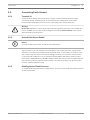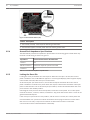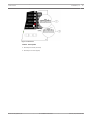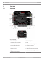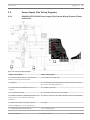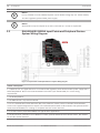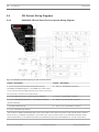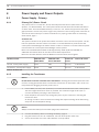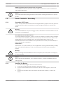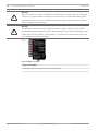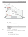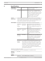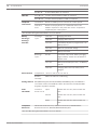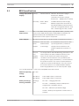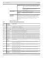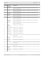
1
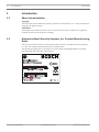
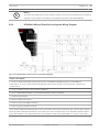
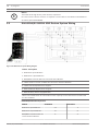
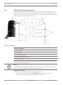
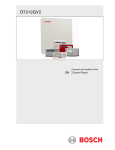
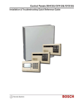
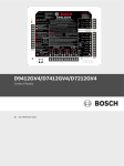
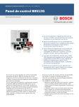
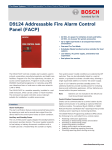
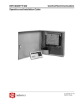
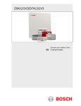
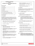
Control Panel
D9412GV4/D7412GV4 v2.00
en
UL Installation Instructions
Control Panel
Table of Contents | en
3
Table of contents
1
Introduction
1.1
About documentation
4
1.2
Determine Bosch Security Systems, Inc. Product Manufacturing Dates
4
2
Installation
5
2.1
Installation Preparation
5
2.2
Enclosure Options
5
2.3
Mounting Enclosure
5
2.4
Installing the Control Panel
6
2.5
Connecting Earth Ground
7
2.5.1
Terminal 10
7
2.5.2
Ground Fault Detect Enable
7
2.5.3
Enabling Ground Fault Detection
7
2.5.4
Ground Fault Impedance Specifications
8
2.5.5
Locking the Reset Pin
3
Diagrams
10
3.1
Faceplates
10
3.2
Power Supply Side Wiring Diagrams
11
4
8
3.2.1
D9412GV4/D7412GV4 Power Supply Side System Wiring Diagram (Power and Phone)
11
3.3
D9412GV4/D7412GV4 Input Points and Peripheral Devices System Wiring Diagram
12
3.4
SDI Devices Wiring Diagrams
14
3.4.1
D9412GV4 SDI and Zonex Devices System Wiring Diagram
14
3.4.2
D7412GV4 SDI and Zonex Devices System Wiring Diagram
15
3.5
D9412GV4/D7412GV4 SDI2 Devices System Wiring
16
3.5.1
SDI2 Bus Wiring Recommendations
18
3.6
Keyswitch Wiring
19
4
Power Supply and Power Outputs
20
4.1
Power Supply - Primary
20
4.1.1
Primary (AC) Power Circuit
20
4.1.2
Installing the Transformer
20
4.2
Power Terminals - Secondary
21
4.2.1
Secondary (DC) Power
21
4.2.2
Installing the Battery
21
4.3
Power Outputs - Circuit Protection
23
4.4
Power Outputs - Total Available Power
24
4.5
Power Outputs - Continuous Power Output Terminals 3, 8, 24, 32, and 36
24
4.6
Power Outputs - Programmable Power Output Terminals 6, 7, and 8
24
4.6.1
Programming
24
4.6.2
Terminals 6 and 7
25
4.6.3
Fire System Power Formula
25
4.6.4
Terminal 8
26
5
Specifications
27
5.1
B520 Specifications
29
5.2
Terminal Wiring Requirements
30
5.3
Compatibilities
32
5.4
Circuit Classes
34
Bosch Security Systens, Inc.
UL Installation Instructions
2012.12 | 02 | F.01U.265.462
4
en | Introduction
Control Panel
1
Introduction
1.1
About documentation
Copyright
This document is the intellectual property of Bosch Security Systems, Inc. and is protected by
copyright. All rights reserved.
Trademarks
All hardware and software product names used in this document are likely to be registered
trademarks and must be treated accordingly.
1.2
Determine Bosch Security Systems, Inc. Product Manufacturing
Dates
Use the serial number located on the product label and refer to the Bosch Security Systems,
Inc. web site at http://www.boschsecurity.com/datecodes/.
The following image shows an example of a product label and highlights where to find the
manufacturing date within the serial number.
2012.12 | 02 | F.01U.265.462
UL Installation Instructions
Bosch Security Systens, Inc.
Control Panel
Installation | en
2
Installation
2.1
Installation Preparation
5
This section contains a general installation procedure and refers to other sections of the
document for detailed instructions. Review this document and the D9412GV4/D7412GV4
Program Entry Guide (P/N: F01U265459) before beginning the installation to determine the
hardware and wiring requirements for the features used. Have the following documentation
available when reading through this guide:
2.2
–
D9412GV4/D7412GV4 Installation and System Reference Guide (P/N: F01U265457)
–
D9412 GV4/D7412GV4 v2.00 Owner’s Manual (P/N: F01U265452)
Enclosure Options
Mount the control panel assembly in any of the Bosch Security Systems, Inc. enclosures listed:
–
D8103 Universal Enclosure (tan)
–
D8109 Fire Enclosure (red) for the D9412GV4 and D7412GV4 Control Panels
–
D8108A Attack Resistant Enclosure (tan)
Refer to the Approved Applications chapter inside the D9412GV4/D7412GV4 v2.00 Installation
and System Reference Guide (P/N: F01U265457) to determine if the application requires a
specific enclosure.
2.3
Mounting Enclosure
1.
Run the necessary wiring throughout the premises.
2.
Mount the enclosure in the desired location. Use all five enclosure mounting holes. Refer
to the diagram for mounting locations and descriptions.
3.
Bosch Security Systens, Inc.
Pull the wires into the enclosure.
UL Installation Instructions
2012.12 | 02 | F.01U.265.462
6
en | Installation
i
Control Panel
Notice!
Electromagnetic interference (EMI) can cause problems on long wire runs.
Figure 2.1: Enclosure Mounting
Callout - Description
1 - Point chart label
2 - Mounting skirt hooks (2)
3 - Module mounting holes (12)
4 - Tamper switch mounting holes (5)
5 - Skirt mounting hole (1)
6 - Enclosure mounting holes (5)
7 - Mounting skirt hook holes (2)
8 - Back of the control panel
9 - Lock down tab
2.4
Installing the Control Panel
1.
Place the control panel over the inside back of the enclosure, aligning the large
rectangular openings of the mounting skirt with the mounting hooks of the enclosure.
Slide the control panel down so that it hangs on the hooks. Refer to Figure 2.1.
2.
Remove the tape from the #6 x 1/4-in. screw in the mounting tab on the control panel.
The screw passes through the mounting tab and into the skirt mounting hole in the
enclosure. Tighten the screw to secure the control panel in the enclosure.
3.
Connect earth ground to the control panel before making any other connections. Refer to
Connecting Earth Ground.
2012.12 | 02 | F.01U.265.462
UL Installation Instructions
Bosch Security Systens, Inc.
Control Panel
Installation | en
2.5
Connecting Earth Ground
2.5.1
Terminal 10
7
To help prevent damage from electrostatic charges or other transient electrical surges,
connect the system to earth ground at Terminal 10 before making other connections.
Recommended earth ground references are a grounding rod or a cold water pipe.
Warning!
!
Do not use telephone or electrical ground for the earth ground connection. Use 14 AWG (1.8
mm) to 16 AWG (1.5 mm) wire when making the connection. Do not connect other control
panel terminals to earth ground.
Ground Fault Detect Enable
2.5.2
i
Notice!
To meet UL 864 requirements, enable Ground Fault Detect.
A ground fault is a circuit impedance to earth ground. The control panel has a ground fault
detection circuit that, when enabled, detects ground faults on Terminals 1 to 9 and 11 to 36.
The control panel also detects and annunciates ground faults on any device connected to it.
If a ground fault condition occurs, the keypads display SERVC GND FAULT and the control
panel sends a GROUND FAULT TROUBLE, AREA 1. When the control panel recognizes that the
ground fault condition is corrected, and remains corrected for between 5 to 45 consecutive
seconds, a Restoral Report is sent.
2.5.3
Enabling Ground Fault Detection
To enable the Ground Fault Detect Enable feature, lock (close) the S4 Ground Fault Detect Pin
on the control panel.
Bosch Security Systens, Inc.
UL Installation Instructions
2012.12 | 02 | F.01U.265.462
8
en | Installation
Control Panel
Figure 2.2: Ground Fault Detect (S4)
Callout - Description
1 - S4 Locked (Closed). Control panels detects ground faults.
2 - S4 Unlocked (Open). Control panel does not detect ground faults.
2.5.4
Ground Fault Impedance Specifications
The table below provides the impedance specifications for detecting ground faults when any
terminal or field wiring is shorted to ground.
Impedance
Control Panel Detects Ground Fault
≤ 300 Ω
Yes
300 Ω to 200 k Ω
Detection depends upon the terminal
≥ 200 k Ω
No
Table 2.1: Ground Fault Impedance Specifications
2.5.5
Locking the Reset Pin
Locking the reset pin disables the control panel. When the reset pin is locked, the control
panel is disabled. CALL FOR SERVICE appears in some keypad displays (SDI2 keypads display
enter Installer Passcode) when the pin is locked down.
On-board outputs (Terminals 6 and 7) and off-board outputs deactivate when the control
panel is disabled. Terminal 8 has power when the output is deactivated. Activation interrupts
power at that terminal. The on-board output (Terminal 8) remains deactivated when the reset
pin is locked in the disable position.
Unlocking the reset pin from the locked position resets the control panel. The control panel
resets all its timers, counters, indexes, and buffers. Any points that restore after a reset do not
generate Restoral Reports.
If the reset pin is placed in the Lock position, and all areas are armed, the control panel will
not answer RPS over a phone line unless the Answer Armed program item has a value other
than zero in it. No entry is required for network or RPS Enhanced direct connection
communication. Refer to RPS Parameters in RPS Help.
2012.12 | 02 | F.01U.265.462
UL Installation Instructions
Bosch Security Systens, Inc.
Control Panel
Installation | en
9
Figure 2.3: Reset Pin
Callout - Description
1 - Reset pin locked (closed)
2 - Reset pin normal (open)
Bosch Security Systens, Inc.
UL Installation Instructions
2012.12 | 02 | F.01U.265.462
10
en | Diagrams
Control Panel
3
Diagrams
3.1
Faceplates
Figure 3.1: Faceplates
Callout - Description
Callout - Description
1 - Charging status LED (yellow)
8 - Ring
2 - Low battery LED (red)
9 - Operation monitor LED (green)
3 - Color-coded battery leads
10 - Accessory connector
4 - Ground fault detect enable
11 - Reset pin
5 - Phone LED (red)
12 - SDI interconnect wiring connector
6 - Tip
13 - SDI2 interconnect wiring connector
7 - Telephone cord connector
2012.12 | 02 | F.01U.265.462
UL Installation Instructions
Bosch Security Systens, Inc.
Control Panel
Diagrams | en
11
3.2
Power Supply Side Wiring Diagrams
3.2.1
D9412GV4/D7412GV4 Power Supply Side System Wiring Diagram (Power
and Phone)
Figure 3.2: Side System Wiring Diagram
Callout - Description
Callout - Description
1 - If required by local AHJ, connect D113
8 - To Output A or Output B
Battery Lead Supervision Module.
2 - Batteries
9 - Listed Audible Signaling Devices rated at 12.0 VDC nominal
(do not use vibrating type horns)
3 - D122/D122L Dual Battery Harness, as
10 - C900V2 (optional)
required
4 - To Supervision Point
11 - Secondary phone line (part of D928)
5 - D1640 Transformer (NFPA applications may
12 - 560 Ω, 2 W end-of-line (EOL) Resistor (P/N: 15-03130-005)
require the use of a D8004 Transformer
Enclosure
6 - D8132 Dual Battery Charger with two
13 - D928
batteries (Batteries are not supervised.)
7 - D192G Bell Supervision Module
Bosch Security Systens, Inc.
14 - To earth ground
UL Installation Instructions
2012.12 | 02 | F.01U.265.462
12
en | Diagrams
i
i
3.3
Control Panel
Notice!
For UL Certified accounts, additional power can be obtained using only a UL Listed auxiliary
12.0 VDC regulated, power-limited power supply.
Notice!
All terminals accept for Outputs A, B, and C (Terminals 6, 7 and 8) are supervised.
D9412GV4/D7412GV4 Input Points and Peripheral Devices
System Wiring Diagram
Figure 3.3: Input Points and Peripheral Devices System Wiring Diagram
Callout - Description
1 - (Optional): For 24 V applications use a UL 1481 Listed regulated, power-limited 24 VDC power supply with a
D130 Relay Module. Refer to the D130 Installation Instructions (P/N: F01U072455) for correct wiring
requirements.
2 - D130 Relay Module
3 - D125B Powered Loop Interface Module
4 - To UL Listed two-wire smoke detectors with a fire rated EOL resistor. Refer to Two-Wire Smoke Detectors
section in the Approved Applications chapter in the D9412GV4/D7412GV4 v2.00 Installation and System Reference
Guide (P/N: F01U265457) for a listing of compatible two-wire smoke detectors.
5 - 1 kΩ EOL resistor (P/N: F01U033966): For typical alarm applications.
6 - D129 Dual Class A Initiation Circuit Module: Provides optional Waterflow Alarm Retard feature. Not suitable
for two-wire smoke detectors.
2012.12 | 02 | F.01U.265.462
UL Installation Instructions
Bosch Security Systens, Inc.
Control Panel
i
Diagrams | en
13
Notice!
For D129, use zero retard except for waterflow devices.
All external connections except Terminal 5 (battery positive) are power limited.
Bosch Security Systens, Inc.
UL Installation Instructions
2012.12 | 02 | F.01U.265.462
14
en | Diagrams
Control Panel
3.4
SDI Devices Wiring Diagrams
3.4.1
D9412GV4 SDI and Zonex Devices System Wiring Diagram
Figure 3.4: D9412GV4 System Wiring Diagram, SDI and Zonex Devices
Callout ᅳ Description
Callout ᅳ Description
1 ᅳ Up to 16 supervised D1265, D1255 (all versions),
6 ᅳ Zonex 1: 15 D8128Ds maximum1
D1255RB, D1256RB Keypads, or D1257RB Fire Annunciators,
or up to 8 supervised D1260 Keypads (all versions) (maximum
16 supervised, maximum 32 unsupervised)
2 ᅳ Up to 8 D9210C Access Control Interface Modules
7ᅳ Zonex 2: 15 D8128Ds maximum1
3 ᅳ Up to 2 B426/B420/DX4020 or ITS-DX4020-G Network
8 ᅳ Zonex 1: Up to 8 D129s maximum1
Interface Modules
4 ᅳ D8125 POPEX Module
9 ᅳ Zonex 2: Up to 8 D8129s maximum1
5 ᅳ Up to 119 D9127U/T POPITs
The number of D8129 OctoRelays that can be connected to each Zonex terminal on the control panel is limited
1
by the number of D8128D OctoPOPITs connected to the same terminal. Refer to the D8128D Installation Guide
(P/N: F01U070537) or the D8129 Operation and Installation Guide (P/N: F01U036302) for specific information.
2012.12 | 02 | F.01U.265.462
UL Installation Instructions
Bosch Security Systens, Inc.
Control Panel
i
3.4.2
Diagrams | en
15
Notice!
Terminals 24 through 36 are power limited, supervised. Fire and Intrusion devices must be on
separate circuits. Refer to ICP-SDI-9114 Installation Instructions (P/N: F01U030068)
D7412GV4 SDI and Zonex Devices System Wiring Diagram
Figure 3.5: D7412GV4 SDI and Zonex Devices System Wiring Diagram
Callout - Description
1 - Up to 16 supervised D1265, D1255 (all versions), D1255RB, D1256RB Keypads, or D1257RB Fire
Annunciators, or up to 8 supervised D1260 Keypads (all versions) (maximum 16 supervised, maximum 32
unsupervised)
2 - Up to 2 D9210C Access Control Interface Modules
3 - Up to 2 B426/B420/DX4020 or ITS-DX4020-G Network Interface Modules
4 - D8125 POPEX Module
5 - Up to 67 D9127U/T POPITs
6 - Zonex 1: Up to 9 D8128Ds maximum
7 - Zonex 1: Up to 8 D8129s maximum1
1
The number of D8129 OctoRelays that can be connected to each Zonex terminal on the control panel is limited
by the number of D8128D OctoPOPITs connected to the same terminal. Refer to the D8128D Installation Guide
(P/N: F01U070537) or the D8129 Operation and Installation Guide (P/N: F01U036302) for specific information.
Bosch Security Systens, Inc.
UL Installation Instructions
2012.12 | 02 | F.01U.265.462
16
en | Diagrams
Control Panel
Notice!
i
3.5
Terminals 24 through 36 are power limited, supervised.
Fire and Intrusion devices must be on separate circuits. Refer to ICP-SDI-9114 Installation Instructions (P/N: F01U030068).
D9412GV4/D7412GV4 SDI2 Devices System Wiring
Figure 3.6: SDI2 Devices System Wiring Diagram
Callout - Description
1 - B208 Octo-input Modules1
2 - B308 Octo-output Modules1
3 - B426/B420 Conettix Ethernet Communication Module1
4 – B810 wireless receiver or B820 SDI2 Inovonics Interface Modules1
5 – B920 Two-line Alphanumeric Keypad1
6 - B930 ATM Style Alphanumeric Keypad1
7 - B520 Auxiliary Power Supply Module1
Refer to the table below for information on the capacity of each GV4 Series Control Panel
1
for SDI2 modules.
D9412GV4/D7412GV4 Capacities
Module
D9412GV4
D7412GV4
B208 Octo-input Modules
24
71
B308 Octo-output Modules
12
62
B426/B420 Conettix Ethernet
23
23
Communication Module
2012.12 | 02 | F.01U.265.462
UL Installation Instructions
Bosch Security Systens, Inc.
Control Panel
Diagrams | en
Module
D9412GV4
BB810/B820 SDI2 Inovonics
4
17
D7412GV4
1
1
16
16
16
16
8
8
Interface Modules
B920 Two-line Alphanumeric
Keypad5
B930 ATM Style Alphanumeric
Keypad (SDI2)
5
B520 Auxiliary Power Supply
Module
For the D7412GV4, only 5 inputs are available on the Octo-input at address 7.
1
For the D7412GV4, only 4 outputs are available on the Octo-output at address 6.
2
For the B426/B420, only two devices can be installed at one time.
3
For the B810 and B820 wireless receivers, only one device can be installed (either B810 or
4
B820 receiver) at one time.
For the B920 and B930, a total of 16 keypads in any combination can be installed at one
5
time.
i
Notice!
Terminals 33 through 36 are power limited, supervised. Fire and Intrusion devices must be on
separate circuits. Refer to ICP-SDI-9114 Installation Instructions (P/N: F01U030068).
Bosch Security Systens, Inc.
UL Installation Instructions
2012.12 | 02 | F.01U.265.462
18
en | Diagrams
Control Panel
SDI2 Bus Wiring Recommendations
3.5.1
Use the following SDI2 bus wiring recommendations for SDI2 installation. The SDI2 bus is
used by the GV4 Control Panel and corresponding modules to communicate with one another.
Modules can be connected via home run, daisy chain, or single level T-tapped anywhere on the
SDI2 bus. Please reference Figure 2.7 below.
Figure 3.7: SDI2 Bus Wiring
Callout ᅳ Description
1 ᅳ Control panel
2 ᅳ SDI2 module
3 ᅳ Daisy chained wiring
4 ᅳ Single-level T-tapped wiring
5 ᅳ Home run wiring
If the voltage at any device is below the minimum, you must add an auxiliary power supply to
the system to power these devices.
i
Notice!
The absolute lowest voltage for the SDI2 devices is 10 VDC at the device terminals when in
normal operation, with a fully charged battery on the system.
Maximum cable lengths
The following rules must be followed when wiring the SDI2 bus.
–
The SDI2 bus requires the use of non-shielded cable from 12 AWG to 22 AWG.
–
Maximum overall cable length based on the table listed below:
2012.12 | 02 | F.01U.265.462
UL Installation Instructions
Bosch Security Systens, Inc.
Control Panel
Diagrams | en
Cable
Overall
Cable
Overall
Cable
Overall
Cable
Overall
capacitance
cable
capacitance
cable
capacitance
cable
capacitance
cable
length
length
length
19
length
pF/ft
ft
pF/ft
ft
pF/ft
ft
pFf/ft
ft
< 17
7500
22
6363
27
5185
32
4400
18
7500
23
6086
28
5000
33
4242
19
7350
24
5800
29
4828
34
4100
20
7000
25
5600
30
4700
35
4000
21
6666
26
5385
31
4516
36
3800
Table 3.1: Maximum cable length
i
i
3.6
Notice!
Use Non-shielded cable only.
Notice!
Maximum capacitance of 140nF (140,000 pf) per system. Contact the wire manufacturer for
the capacitance ratings of the wire being used.
Keyswitch Wiring
Figure 3.8: Keyswitch Wiring
Callout - Description
1 - Maintained keyswitch
2 - Momentary keyswitch
3 - Common
4 - Point Input
5 – End of Line (EOL) resistor*
6 - Open on a circuit arms the area
7 - Short on a circuit toggles the arming state
*Use proper EOL for the specific device you are using.
Bosch Security Systens, Inc.
UL Installation Instructions
2012.12 | 02 | F.01U.265.462
20
en | Power Supply and Power Outputs
Control Panel
4
Power Supply and Power Outputs
4.1
Power Supply - Primary
4.1.1
Primary (AC) Power Circuit
The primary source is a 16.5 VAC, 40 VA, internally-fused transformer (Bosch Security
Systems, Inc. Model D1640). The control panel draws 225 mA when idle and 300 mA when in
an alarm state. The total available auxiliary current is 1.4 A. Transient suppressors and spark
gaps protect the circuit from power surges. This protection relies on the ground connection at
Terminal 10. Ensure that you connect Terminal 10 to a proper ground. Refer to Connecting
Earth Ground, page 7.
AC Power Fail
The system indicates an AC power failure when Terminals 1 and 2 do not have power. The AC
Fail Time parameter sets the number of minutes or seconds without AC power before the
control panel acknowledges the failure and the number of minutes or seconds after the power
returns before the control panel acknowledges restored power.
Refer to the D9412GV4/D7412GV4 v2.00 Program Entry Guide (P/N: F01U265459) for
additional information about AC Fail Time and UL 864 requirements.
Reference the table below to view the Modem4 communication format signals.
Modem4 Events
Modem4 code
Modem4 Code
Contact ID
D6500 Mode
Bosch SIA Mode
Events
Contact ID Codes
AC Fail - mains power supply
Pssss
NAT
AC Loss
1 301 00 000
AC Restore - mains power supply
Rsss0
NAR
AC Loss
3 301 00 000
Table 4.1: AC Power Fail
Installing the Transformer
4.1.2
Notice!
i
Do not short-circuit the terminals of the transformer. Shorting the terminals opens the internal fuse, causing permanent failure. Connect the transformer to Terminals 1 and 2 of the control panel before plugging it into the power source.
1.
Use 18 AWG (1.22 mm) wire (minimum) to connect the transformer to the control panel.
The wire length should be as short as possible. The maximum length is 50 ft (15 m).
Connect the battery and plug in the transformer.
2.
Route telephone and sensor loop wiring away from any AC conductors, including the
transformer wire.
AC wiring can induce noise and low level voltage into adjacent wiring. Route data wiring
away from AC and telephone wiring.
i
Notice!
Always connect the battery first and then plug in the transformer.
3.
Connect the battery. Refer to Installing the Battery, page 21
4.
Plug the transformer into an unswitched, 120 VAC 60 Hz power outlet only.
5.
Secure the transformer to the outlet with the screw provided.
2012.12 | 02 | F.01U.265.462
UL Installation Instructions
Bosch Security Systens, Inc.
Control Panel
Power Supply and Power Outputs | en
21
D8004 Transformer Enclosure Required for Fire Systems
Use the D8004 Transformer Enclosure for the D1640 Transformer in fire and combined fire
and burglary applications.
i
Notice!
Check with the Authority Having Jurisdiction (AHJ) about mounting transformers on specific
circuits.
Power Terminals - Secondary
4.2
Secondary (DC) Power
4.2.1
A 12 V, 7 Ah (up to 18 Ah) sealed lead-acid rechargeable battery supplies secondary power for
auxiliary and alarm outputs, and powers the system during interruptions in primary (AC)
power.
Warning!
!
Use Lead Acid Batteries Only: The charging circuit is calibrated for lead-acid batteries. Do not
use gel-cell or nicad batteries.
Extra Batteries Increase Back-up Time
To increase battery back-up time, connect a second 12 V battery in parallel to the first battery.
Use a D122/D122L Dual Battery Harness to ensure proper and safe connection. Refer to the
Standby Battery and Current Rating Chart in the Approved Applications section of the
D9412GV4/D7412GV4 v2.00 Installation and System Reference Guide (P/N: F01U265457) for
battery standby time calculations.
D1218 Battery
The D1218 is a 12 V, 18 Ah battery for use in applications requiring extended battery standby
time. Up to two D1218 batteries can be connected when used with a D122 Dual Battery
Harness.
Warning!
!
i
4.2.2
When connecting two D1218 Batteries to the control panel, the control panel can charge up
to 36 Ah of battery.
Notice!
When using two D1218 batteries, use a separate enclosure, a D122L Dual Battery Harness,
and long leads.
Installing the Battery
1.
Place the battery upright in the base of the enclosure.
2.
Locate the red and black leads supplied in the literature pack.
3.
Connect the black battery lead to Terminal 4, and then to the negative (-) side of the
battery.
4.
Connect the red battery lead to Terminal 5, and then to the positive (+) side of the
battery.
Bosch Security Systens, Inc.
UL Installation Instructions
2012.12 | 02 | F.01U.265.462
22
en | Power Supply and Power Outputs
Control Panel
Warning!
High current arcs are possible. The positive (red) battery lead and Terminal 5 can create high
!
current arcs if shorted to other terminals or the enclosure. Use caution when working with
the positive lead and Terminal 5. Always disconnect the positive (red) lead from the battery
before removing it from Terminal 5.
Warning!
The battery terminals and wire are not power limited. A 0.250 in (6.4 mm) space must be
!
maintained between the battery terminals, battery wiring, and all other wiring. Battery wiring
cannot share the same conduit, conduit fittings, or conduit knock-outs with other wiring. Refer to the Battery Terminals illustration.
Figure 4.1: Battery Terminals
Callout - Description
1 - Battery terminals. Terminal 5 is non-power limiting.
2012.12 | 02 | F.01U.265.462
UL Installation Instructions
Bosch Security Systens, Inc.
Control Panel
Power Supply and Power Outputs | en
23
Figure 4.2: Non-PowerLimited Wiring
Callout ᅳ Description
1 ᅳ Conduit required for use with external batteries.
2 ᅳ Battery wires
3 ᅳ 0.25 in (6.4 mm) minimum. To ensure proper spacing, use tie-wraps or similar devices to
secure wires.
4 ᅳ Relay output wires
5 ᅳ Input or Zone wires
6 ᅳ Standby battery
4.3
Power Outputs - Circuit Protection
5 PTC’s protect the control panel from short circuits on the continuous and programmable
power outputs. The PTC assignments are listed below.
PTC CB2 protects:
–
Terminal 3: Auxiliary Power
PTC CB4 protects:
–
Terminal 6: Output A (Alarm Power Output)
–
Terminal 7: Output B (Alternate Alarm Power Output)
Bosch Security Systens, Inc.
UL Installation Instructions
2012.12 | 02 | F.01U.265.462
24
en | Power Supply and Power Outputs
–
Control Panel
Terminal 8: Output C (Switched Auxiliary Power)
PTC CB5 protects Terminal 24: Zonex Power.
PTC CB1 protects Terminal 32: SDI Power +.
PTC CB3 protects Terminal 36: SDI2 Power +.
Required by UL:
–
All devices powered from a power output are to be supervised.
–
Power outputs are not shared between fire and non-fire devices unless all devices are in
conduit within 20 ft, and in the same room.
4.4
Power Outputs - Total Available Power
The system produces up to 1.4 A of combined power at 12.0 VDC Nominal for all powered
devices. The outputs listed below share the available power. These outputs are shown as red
circles on the faceplate.
–
Terminal 3 - Auxiliary Power. Use this terminal to power devices requiring continuous
power.
–
Terminal 6 (Output A) - Alarm Power Output. Programmable relay normally open, power
on alarm.
–
Terminal 7 (Output B) - Alternate Alarm Power Output. Programmable relay normally
open, power on alarm.
–
Terminal 8 (Output C) - Switched Auxiliary Power. Programmable relay normally closed,
switches power off when the Sensor Reset command is executed.
–
Terminal 24 - Zonex Power. Use this terminal to power Zonex modules such as the
D8125, D8128D, and D8129 Modules.
–
Terminal 32 - SDI Power +. Use this terminal to power serial device interface (SDI)
devices such as keypads, the D9210C Wiegand Control Interface Module, the ICPSDI-9114 module, and other compatible SDI devices.
–
Terminal 36 - SDI2 Power +. Use this terminal to power serial device interface 2 (SDI2)
devices such as B208, B308, B426, B810, B920, B930, and other compatible SDI2
devices.
4.5
Power Outputs - Continuous Power Output Terminals 3, 8, 24,
32, and 36
The continuous current draw for powered devices connected to Terminals 3, 8, 24, 32, and 36,
and the accessory connector must not exceed 1.4 A. Devices powered from these outputs
must operate at 12.0 VDC Nominal.
Power Restricted for Fire and Combined Fire and Burglary Systems
Use the Fire System Power Formula to calculate the current available for fire and combined
fire and burglary systems (refer to Power Outputs - Programmable Power Output Terminals 6, 7,
and 8, page 24).
4.6
Power Outputs - Programmable Power Output Terminals 6, 7,
and 8
4.6.1
Programming
The power outputs at Terminals 6, 7, and 8 are programmed as Outputs A, B, and C. All
outputs are programmed in the Outputs section. Outputs are assigned a output type, (Fire
Bell, for example) when they are assigned to an area. Outputs can be assigned to one or more
areas. The Bosch defaults set Output A (Terminal 6) as a Steady Alarm Bell output, Output B
(Terminal 7) as a Pulsed Fire Bell output, and Output C (Terminal 8) as a Verification or Reset
output for smoke detectors. The D9412GV4/D7412GV4 v2.00 Program Entry Guide (P/N:
2012.12 | 02 | F.01U.265.462
UL Installation Instructions
Bosch Security Systens, Inc.
Control Panel
Power Supply and Power Outputs | en
25
F01U265459) contains complete instructions for programming outputs. Refer to Terminals 6
and 7, page 25, Fire System Power Formula, page 25, and Terminal 8, page 26 for
descriptions of the functions of each terminal. Refer to the Bell Parameters section of the
program to set the Fire Bell, Alarm Bell, and Gas Bell output responses for outputs. Four
annunciation patterns are available: Steady, Pulsed, California Standard, Temporal Code 3,
and Temporal Code 4.
Voltage Output at Terminals 6, 7, and 8
If Terminals 6, 7, and 8 do not provide the expected output, check:
–
Programming for Outputs A, B, and C in the outputs section of the program. For proper
operation, do not program a Panel Wide Output the same as an Area Wide Output.
–
Bell Parameters section of the program to confirm that the Alarm, Fire, and Gas Bell
responses are programmed for the expected duration and pattern.
–
Point Assignments section to confirm that each point is programmed for the expected
local response.
4.6.2
Terminals 6 and 7
When activated, Terminals 6 (Output A) and 7 (Output B), provide positive (+) 12.0 VDC
Nominal power output. Use the power at Terminals 6 and 7 to power bells, siren drivers,
piezoelectric fire sounders, electronic horns, or other devices.
Programming determines the format of the output and the conditions that activate it. One selfresetting circuit breaker protects Terminals 6, 7, and 8 against shorts. When using Output A or
Output B to activate notification appliance circuits in UL Listed fire alarm applications, install
a D192G Indicating Circuit Module.
Available Power
The system combines the 1.4 A of primary power produced by the power supply with the
secondary power source (the battery) to produce a total of 2.0 A of alarm power at 12.0 VDC
Nominal. Terminals 6 and 7 share the available alarm power.
Power Restricted for Fire and Combined Fire and Burglary Systems
Fire systems are prohibited from using the battery for determining alarm power. Use the fire
system power formula described in Fire System Power Formula, page 25 to calculate the
current available for fire and combined fire and burglary systems.
4.6.3
Fire System Power Formula
To calculate the current available at Terminals 6 and 7 for fire and combined fire and burglary
systems:
1.
Add together the current draws for all devices connected to Terminals 3, 8, 24, and 32,
and the accessory connector. This is the total current required for the normal standby
condition (NSC).
2.
The current available for NSC is 1.4 A. Subtract the NSC current required calculated in
Step 1 from the NSC current available, 1.4 A. The difference is the alarm current available
for Terminals 6 and 7.
In formula format:
1.4 A - NSC current required (Step 1) = Alarm current available
Refer to the Approved Applications chapter inside the D9412GV4/D7412GV4 v2.00 Installation
and System Reference Guide (P/N: F01U265457) for module or accessory current requirements.
Bosch Security Systens, Inc.
UL Installation Instructions
2012.12 | 02 | F.01U.265.462
26
en | Power Supply and Power Outputs
4.6.4
Control Panel
Terminal 8
Terminal 8 provides continuous positive (+) 12.0 VDC Nominal power. Output C interrupts the
power at Terminal 8 when activated. Use Terminal 8 to power smoke detectors or other
devices that are reset by interrupting power. One self-resetting circuit breaker protects
Terminals 6, 7, and 8 against shorts.
Verification/Reset Output
The default program sets Output C (Terminal 8) as a verification and reset output. Refer to
Output Parameters and Point Assignments in the D9412GV4/D7412GV4 v2.00 Program Entry
Guide (P/N: F01U265459) for instructions on programming verification/reset outputs and
points.
Performing a sensor reset at a keypad produces a five-second output activation of verification/
reset outputs. The control panel ignores verification and reset points during the five-second
output activation.
2012.12 | 02 | F.01U.265.462
UL Installation Instructions
Bosch Security Systens, Inc.
Control Panel
5
Specifications | en
27
Specifications
Voltage Input
Primary:
Terminals 1 and 2 16.5 VAC 40 VA class 2 plug-in
(Power Supply)1
transformer (D1640)
Secondary: Terminals 4 and 5 Sealed lead-acid rechargeable battery
(12.0 VDC, 7 Ah or 12.0 VDC, 17.2 or 18
Ah). The control panel supports up to two
12.0 VDC, 7 Ah batteries using the D122/
D122L Dual Battery Harness or two
D1218 (12.0 VDC, 17.2 or 18 Ah)
batteries using a D122/D122L.
Current
Requirement
Control Panel: Idle 225 mA; Alarm 300 mA. Refer to the Current Rating
Chart for Standby Battery Calculations section in the D9412GV4/D7412GV4
v2.00 Installation and System Reference Guide (P/N: F01U265457) for the
current draw requirements of other system components.
Power Outputs2
All external connections are power-limited except battery terminals
Continuous
Terminals 3,
1.4 A maximum at 12.0 VDC Nominal
Power
24, 32, 36
(continuous supply) total for all devices
Outputs
and outputs supplied at Terminals 3, 24,
32, and 36.
Alarm Power
Terminals 6
2.0 A maximum at 12.0 VDC Nominal
Output
and 7
output. Output can be steady or one of
four pulsed patterns depending on
programming. Refer to Outputs in RPS
Help.
Switched
Terminal 8
Aux Power
1.4 A maximum at 12.0 VDC Nominal
output. Continuous output is interrupted
by Sensor Reset, or alarm verification
depending on programming. Refer to
Outputs in RPS Help.
Fire and Fire/ To comply with UL 985 and 864 listing standards for fire
Burglary
alarm systems, the total combined continuous and alarm
Systems
current draw for the system during alarm conditions must
be limited to 1.4 A provided by the primary power supply
(rectified AC). If current draw for the system exceeds 1.4
A, use a UL Listed 12 VDC regulated, power limited
auxiliary power supply module such as the B520 (refer to
the Keyswitch Wiring section).
Requires a UL Listed power supply.
1
For UL 864 applications, refer to 6.0 Compatibilities for compatible devices.
2
Minimum
10.2 VDC
Operating
Voltage
SDI Bus
Bosch Security Systens, Inc.
SDI Bus A+:
9 VDC 15000 ft (4572 m) maximum
UL Installation Instructions
2012.12 | 02 | F.01U.265.462
28
en | Specifications
Control Panel
SDI2 Bus
Telephone
Connections
SDI Bus B-:
9 VDC 15000 (4572 m) maximum
SDI2 Bus A+;
12 VDC nominal 7500 ft (2286 m) maximum3
SDI2 Bus B-:
12 VDC nominal (7500 ft) (2286 m) maximum3
Connection:
RJ31X or RJ38X jack can connect the control panels.
Two telco
Bosch Security Systems, Inc. D928 Dual Phone Line
lines:
Module required for two phone line service. Supervision
supplied by the control panel.
See SDI2 Bus Wiring Recommendations for more details
3
Battery
Discharge
Discharge/
Cycle:
Recharge
Schedule
13.9 VDC
Charging float level.
13.8 VDC
Charging status LED on.
12.1 VDC
Low Battery Reports if programmed. Low
Battery LED on.
Recharge
10.2 VDC
Minimum operational voltage.
10.0 VDC
Battery load shed.
AC ON
Load shed relay resets, battery charging
Cycle:
begins, Battery Trouble and AC Restoral
Reports sent.
13.7 VDC
Battery Restoral Report sent, Low Battery
LED off.
13.9 VDC
Charging status LED off, battery float
charged.
Environmental
Temperature: +32゚F to +120゚F (0゚C to +49゚C)
Relative
Maximum 93% non-condensing
Humidity:
Arming Stations
B920/B930 Keypads,D1255/D1255B/D1255RB Keypads, D1256RB Fire
Command Centers; D1257RB Fire Alarm Annunciators; D1260/D1260B
Keypads; Keyswitch; Keyfobs
Point
On-board
Thresholds
Points 1 to 8
Open
Greater than 3.7 VDC, but less than 5.0
VDC.
Normal
Greater than 2.0 VDC, but less than 3.0
VDC
Short
Greater than 0.0 VDC, but less than 1.3
VDC.
Compatible
D8103 Universal Enclosure, D8109 Fire Enclosure, D8108A Attack
Enclosures
Resistant Enclosure, BATB-40/BATB-80 Battery Box
See SDI2 Bus Wiring Recommendations for more details
2
2012.12 | 02 | F.01U.265.462
UL Installation Instructions
Bosch Security Systens, Inc.
Control Panel
5.1
Specifications | en
29
B520 Specifications
Voltage Input (Power Primary:
18 VAC terminal
Supply)
18.0 VAC, 50 VA class 2 plug-in
transformer -TR1850
(18.0 VAC, 50 VA class 2 plug-in
transformer – TR1850-CA for Canada)
Secondary:
Batt 1, Batt 2
The B520 Auxiliary Power Supply
terminals
Module supports the connection of
two independantly monitored sealed
lead-acid rechargeable batteries (12.0
VDC, 7 Ah through 12.0 VDC, 36 Ah).
Current
Requirements
Refer to the B520 Auxiliary Power Supply Module Battery Standby Chart
section in the B520 Auxiliary Power Supply Module Installation and
Operation Guide (P/B: F01U265445) for the current draw
requirements of other system components.
Power Outputs*
All external connections are power-limited except battery terminals
Continuous SDI2 Out, AUX
2.0 A maximum at 11.5 to 12.2 VDC
Power
PWR terminals
(special application) (continuous
Outputs
(rated range)
supply) total for all devices and
outputs supplied at Terminals 1-4,
6-36.
Fire and
To comply with UL 985 and 864 listing standards for fire
Fire/
alarm systems, the total combined continuous and
Burglary
alarm current draw for the system during alarm
Systems
conditions must be limited to 2.0 A provided by the
primary power supply (rectified AC). If current draw for
the system exceeds 2.0 A, remove connected devices
until the current draw falls below 2.0 A. Then connect
the removed devices to an additional B520 Auxiliary
Power Supply Module or to an external power supply
*For UL 864 applications, refer to the Compatible Accessories section.
Minimum Operating
10.2 VDC
Voltage
SDI2 Bus
SDI2 Bus A:
8 VDC-2000 ft (610 m) maximum
SDI2 Bus B:
8 VDC-2000 ft (610 m) maximum
Battery Discharge/
Discharge
13.2 VDC – Charging float level.
Recharge Schedule
Cycle
12.0 VDC – Low Battery and AC Fail Reports if
programmed. Low Battery LED on.
10.2 VDC – Minimum operational voltage.
9.8 VDC – Battery load (operation continue if AC is
present).
Bosch Security Systens, Inc.
UL Installation Instructions
2012.12 | 02 | F.01U.265.462
30
en | Specifications
Control Panel
Recharge Cycle AC ON – Load shed relay resets, battery charging
begins, Battery Trouble and AC Restoral Reports
sent.
12.6 VDC – Battery Restoral Report sent, Low
Battery LED off.
Environmental
Temperature:
+32゚F to +120゚F (0゚C to +49゚C)
Relative
Maximum 93% non-condensing
Humidity:
Compatible
D8103 Universal Enclosure (requires B12 mounting plate), D8108A
Enclosures
Attack Enclosure (requires B12 mounting plate), B10 Enclosure,
D8004 Transformer Enclosure, D2203 Enclosure, BATB-80 Enclosure,
BATB-40 Enclosure (requires B12 mounting plate), AE1, AE2
Enclosures
Table 5.1: B520 Specifications
Terminal Wiring Requirements
5.2
Terminal Terminal
Requirements
No
Description
1
AC
18 AWG min (up to 14 AWG max)
2
AC
18 AWG min (up to 14 AWG max)
3
+ AUX POWER
Terminal accommodates 14 to 22 AWG, use appropriate wire size based on current.
4
BATTERY -
Bosch supplied wire lead, included with panel.
5
BATTERY +
Bosch supplied wire lead, included with panel.
6
OUTPUT A
Terminal accommodates 14 to 22 AWG, use appropriate wire size based on current.
7
OUTPUT B
Terminal accommodates 14 to 22 AWG, use appropriate wire size based on current.
8
OUTPUT C
Terminal accommodates 14 to 22 AWG, use appropriate wire size based on current.
9
COMMON
Terminal accommodates 14 to 22 AWG, use appropriate wire size based on current.
10
EARTH
14 to 16 AWG
GROUND
11
POINT 1
Terminal accommodates 14 to 22 AWG, use appropriate wire size based on loop
resistance less than 100 Ω.
12
13
POINT 1/2
Terminal accommodates 14 to 22 AWG, use appropriate wire size based on loop
COMMON
resistance less than 100 Ω.
POINT 2
Terminal accommodates 14 to 22 AWG, use appropriate wire size based on loop
resistance less than 100 Ω.
14
POINT 3
Terminal accommodates 14 to 22 AWG, use appropriate wire size based on loop
resistance less than 100 Ω.
15
POINT 3/4
Terminal accommodates 14 to 22 AWG, use appropriate wire size based on loop
COMMON
resistance less than 100 Ω.
2012.12 | 02 | F.01U.265.462
UL Installation Instructions
Bosch Security Systens, Inc.
Control Panel
Terminal Terminal
No
Description
16
POINT 4
Specifications | en
31
Requirements
Terminal accommodates 14 to 22 AWG, use appropriate wire size based on loop
resistance less than 100 Ω.
17
POINT 5
Terminal accommodates 14 to 22 AWG, use appropriate wire size based on loop
resistance less than 100 Ω.
18
19
POINT 5/6
Terminal accommodates 14 to 22 AWG, use appropriate wire size based on loop
COMMON
resistance less than 100 Ω.
POINT 6
Terminal accommodates 14 to 22 AWG, use appropriate wire size based on loop
resistance less than 100 Ω.
20
POINT 7
Terminal accommodates 14 to 22 AWG, use appropriate wire size based on loop
resistance less than 100 Ω.
21
22
POINT 7/8
Terminal accommodates 14 to 22 AWG, use appropriate wire size based on loop
COMMON
resistance less than 100 Ω.
POINT 8
Terminal accommodates 14 to 22 AWG, use appropriate wire size based on loop
resistance less than 100 Ω.
23
ZONEX
22 AWG min (up to 14 AWG max)
COMMON
24
ZONEX POWER 22 AWG min (up to 14 AWG max)
25
ZONEX IN 2*
22 AWG min (up to 14 AWG max)
26
ZONEX OUT 2*
22 AWG min (up to 14 AWG max)
27
ZONEX IN 1
22 AWG min (up to 14 AWG max)
28
ZONEX OUT 1
22 AWG min (up to 14 AWG max)
29
SDI COMMON
Terminal accommodates 14 to 22 AWG, use appropriate wire size based on peripheral
device current.
30
SDI DATA
22 AWG min (up to 14 AWG max)
BUS B
31
SDI DATA
22 AWG min (up to 14 AWG max)
BUS A
32
SDI POWER
Terminal accommodates 14 to 22 AWG, use appropriate wire size based on peripheral
device current.
33
SDI2 COMMON Terminal accommodates 14 to 22 AWG, use appropriate wire size based on peripheral
device current.
34
SDI2 DATA
22 AWG min (up to 14 AWG max)
BUS B
35
SDI2 DATA
22 AWG min (up to 14 AWG max)
BUS A
Bosch Security Systens, Inc.
UL Installation Instructions
2012.12 | 02 | F.01U.265.462
32
en | Specifications
Terminal Terminal
Control Panel
Requirements
No
Description
36
SDI2 POWER
Terminal accommodates 14 to 22 AWG, use appropriate wire size based on peripheral
device current.
*D9412GV4 only. Terminals 25 and 26 are NOT USED on the D7412GV4 Control Panel.
Compatibilities
5.3
i
Model
Notice!
Where the fire alarm transmitter is sharing on-premise communications equipment, the
shared equipment must be UL Listed (ITE or fire protective signaling).
Title
UL 864
UL
Intrusion
985
cUL
Intrusion
B930
ATM Style Alphanumeric Keypad
X
X
X
B920
Two-line Alphanumeric Keypad
X
X
X
B208
Octo-input Module
X
X
X
X
B308
Octo-output Module
X
X
X
X
3
B810
RADION receiver SD
X
X
B820
Inovonics Interface2 Module
X
X
B426/B420
Conettix Ethernet Communication Module
X
X
X
X
B520
Auxiliary Power Supply Module
X
X
X
X
D113
Battery Lead Supervision Module
X
X
X
X
D122/D122L
Dual Battery Harness
X
X
X
D125B
Powered Loop Interface Module
X
X
X
D126
Standby Battery (12V, 7Ah)
D129
Dual Class A Initiation Circuit Module
X
X
X
D130
Relay Module
X
X
X
D185
Reverse Polarity Module
X
X
X
D192G
Bell Circuit Supervision Module
X
X
X
D279A
Independent Zone Control (On-Board and OctoPOPIT
X
X
Points)
D720R
LED Keypad (red)
X
X
X
D720W
LED Keypad (white)
X
X
X
D928
Dual Phone Line Switcher
X
X
X
X
D1255RB
Fire Keypad
X
X
X
X
D1256RB
Fire Keypad
X
X
X
D1257RB
Fire Alarm Annunciator
X
X
X
2012.12 | 02 | F.01U.265.462
UL Installation Instructions
X
Bosch Security Systens, Inc.
Control Panel
Model
Specifications | en
Title
UL 864
UL
Intrusion
985
D1218
33
cUL
Intrusion
12 V, 17.2 Ah Rechargeable Battery
D1255/D1255B Keypads (General Purpose)
X
X
X
D1255W
Text Keypad (white)
X
X
X
D1260/
Keypads
X
X
X
X
X
D1260B2
D1640
16.5 VAC 40 VA Transformer
X
D1640-CA
16.4 VAC 40 VA Transformer for Canada
D8004
Transformer Enclosure
X
X
X
D8125
POPEX Module
X
X
X
D8125MUX
Multiplex Bus Interface
X
X
X
D8128D
OctoPOPIT Module
X
X
X
X
D8129
OctoRelay Module
X
X
X
X
D8130
Release Module
X
X
X
D8132
Battery Charger Module
X
X
X
D9127U/T
POPIT Module
X
X
X
X
D9210C
Access Control Interface Module
X
X
X
X
DX4010V2
USB/Serial Interface Module
DX4020
Network Interface Module
X
X
X
X
ITS-DX4020-G
GPRS/GSM Communicator
X
X
X
ICP-SDI-9114
SDI Splitter
X
X
X
IST-EZTS
Tamper Switch
X
X
X
X
X
ISW-D8125CW- Commercial Wireless Interface Module
V2
ZX776Z
PIR Motion Sensor [15 m (50 ft)] with POPIT
X
ZX794Z
PIR Motion Sensor [24 m (80 ft)] with POPIT
X
ZX865
PIR/Microwave Motion Sensor with POPIT
X
ZX938Z
PIR Motion Sensor with POPIT
X
ZX970
PIR/Microwave Motion Sensor with POPIT
RFBT-A
RADION speciality
X
RFDL-11-A
RADION TriTech
X
RFDW-RM-A
RADION contact RM
X
RFDW-SM-A
RADION contact SM
X
RFSM-A
RADION smoke
3
3
3
3
3
Bosch Security Systens, Inc.
X
UL Installation Instructions
X
2012.12 | 02 | F.01U.265.462
34
en | Specifications
Model
Control Panel
Title
UL 864
UL
Intrusion
985
RADION repeater
RFPR-12-A
RADION PIR
X
RFPR-C12_A
RADION PIR C
X
RFUN
RADION universal transmitter
X
3
3
3
X
Intrusion
RFRP-A
3
cUL
X
Where the fire alarm transmitter is sharing on-premise communications equipment, the shared equipment must
1
be UL Listed (ITE or fire potective signaling).
Version 1.04 or above.
2
Compatible with version 2.xx or higher
3
Table 5.2: Compatible Accessories1
5.4
Circuit Classes
Onboard Points
Onboard points, points 1 to 8, are Class B, Style B Initiating-Device Circuits.
Zonex Bus or Buses
Zonex buses are Class B, Style 4 Signaling Line Circuits.
Notification Appliance Circuit (NAC)
The control panels do not have an onboard NAC.
A D192G can be added to the control panel (or D8129/B308) and is Class B, Style W.
2012.12 | 02 | F.01U.265.462
UL Installation Instructions
Bosch Security Systens, Inc.
Bosch Security Systems, Inc.
130 Perinton Parkway
Fairport, NY 14450
USA
www.boschsecurity.com
© Bosch Security Systems, Inc., 2012