1
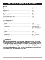
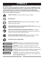
Operator’s Manual 14 IN. ABRASIVE CHOP SAW Model No. 137.375630 CAUTION: ● ● ● ● ● ● Before using this Chop Saw, read this manual and follow all its Safety Rules and Operating Instructions Safety Instructions Installation Operation Maintenance Parts List Español, p. 29 Sears Parts & Repair Center 1-800-488-1222 Customer Help Line For Technical Support 1-800-843-1682 Sears Brands Management Corporation Hoffman Estates, IL 60179 USA See the full line of Craftsman® products at craftsman.com Click on the Craftsman Club® link and join today! Part No. 137.375630001 1 Printed in China TABLE OF CONTENTS SECTION PAGE Warranty ................................................................................................... 2 Product Specifications .............................................................................. 3 Symbols..................................................................................................... 4 Power Tool Safety ..................................................................................... 5 Chop Saw Safety ...................................................................................... 7 Electrical Requirements and Safety .......................................................... 12 Tools Needed for Assembly ...................................................................... 14 Carton Contents ........................................................................................ 14 Know Your Chop Saw ............................................................................... 15 Assembly .................................................................................................. 16 Adjustments .............................................................................................. 18 Operation .................................................................................................. 20 Maintenance ............................................................................................. 22 Troubleshooting Guide ............................................................................. 23 Parts List ................................................................................................... 24 Repair Protection Agreements .................................................................. 27 WARRANTY CRAFTSMAN ONE YEAR FULL WARRANTY FOR ONE YEAR from the date of purchase, this product is warranted against defects in material or workmanship. A defective product will receive free repair or replacement if repair is unavailable. For warranty coverage details or to obtain free repair or replacement, visit the web site: www.craftsman.com This warranty does not cover the blade, which is an expendable part that can wear out from normal use within the warranty period. This warranty is void if this product is ever used while providing commercial services or if rented to another person. This warranty gives you specific legal rights, and you may also have other rights which vary from state to state. Sears Brands Management Corporation, Hoffman Estates, IL 60179 ! WARNING Some dust created by power sanding, sawing, grinding, drilling and other construction activities contains chemicals known to the state of California to cause cancer, birth defects or other reproductive harm. Some examples of these chemicals are: ● Lead from lead-based paints, ● Crystalline silica from bricks and cement and other masonry products, and ● Arsenic and chromium from chemically-treated lumber. Your risk from these exposures varies, depending on how often you do this type of work. To reduce your exposure to these chemicals: work in a well ventilated area, and work with approved safety equipment, such as those dust masks that are specially designed to filter out microscopic particles. 2012/11 2 PRODUCT SPECIFICATIONS MOTOR Type ...................................................................................... Amps ..................................................................................... Maximum hp ......................................................................... Voltage .................................................................................. Hz ......................................................................................... RPM (no load) ....................................................................... Cutting wheel arbor size ....................................................... Cutting wheel size ................................................................. Universal 15 3.5 120 60 3600 1 in. 14 in. CUTTING CAPACITY Cross cut 0° Round ................................................................................ 5 in. Square ............................................................................... 4-3/4 in. × 4-3/4 in. Rectangular ........................................................................ 3 in. × 8-1/4 in. 4-1/4 in. × 6-1/8 in. 4-1/2 in. × 5-1/8 in. Miter cut 45° Round ................................................................................ 4 in. Square ............................................................................... 4 in. × 4 in. Rectangular ........................................................................ 3-1/3 in. × 5 in. Vise clamp angle ................................................................ 0° ~ 45 ° ! WARNING To avoid electrical hazards, fire hazards or damage to the tool, use proper circuit protection. This tool is wired at the factory for 110-120 Volt operation. It must be connected to a 110-120 Volt / 15 Ampere time delay fuse or circuit breaker. To avoid shock or fire, replace power cord immediately if it is worn, cut or damaged in any way. Before using your tool, it is critical that you read and understand these safety rules. Failure to follow these rules could result in serious injury to you or damage to the tool. 3 SYMBOLS WARNING ICONS Your power tool and its Operator’s Manual may contain “WARNING ICONS” (a picture symbol intended to alert you to, and/or instruct you how to avoid, a potentially hazardous condition). Understanding and heeding these symbols will help you operate your tool better and safer. Shown below are some of the symbols you may see. SAFETY ALERT: Precautions that involve your safety. PROHIBITION WEAR EYE PROTECTION: Always wear safety goggles or safety glasses with side shields. WEAR RESPIRATORY AND HEARING PROTECTION: Always wear respiratory and hearing protection. READ AND UNDERSTAND OPERATOR’S MANUAL: To reduce the risk of injury, user and all bystanders must read and understand Operator’s manual before using this product. KEEP HANDS AWAY FROM BLADE: Failure to keep your hands away from the blade will result in serious personal injury. SUPPORT AND CLAMP WORK ! DANGER DANGER: indicates an imminently hazardous situation which, if not avoided, will result in death or serious injury. ! WARNING WARNING: indicates a potentially hazardous situation which, if not avoided, could result in death or serious injury. ! CAUTION CAUTION: indicates a potentially hazardous situation which, if not avoided, may result in minor or moderate injury. CAUTION CAUTION: used without the safety alert symbol indicates a potentially hazardous situation which, if not avoided, may result in property damage. 4 POWER TOOL SAFETY GENERAL SAFETY INSTRUCTIONS BEFORE USING THIS POWER TOOL 8. DO NOT FORCE THE TOOL. It will do the job better and safer at the rate for which it was designed. Safety is a combination of common sense, staying alert and knowing how to use your power tool. 9. USE THE RIGHT TOOL. Do not force the tool or an attachment to do a job for which it was not designed. CAUTION To avoid mistakes that could cause serious injury, do not plug the tool in until you have read and understood the following. 1. 10. USE PROPER EXTENSION CORDS. Make sure your extension cord is in good condition. When using an extension cord, be sure to use one heavy enough to carry the current your product will draw. An undersized cord will result in a drop in line voltage and in loss of power which will cause the tool to overheat. If in doubt, use the next heavier gauge. The smaller the gauge number, the heavier the cord. READ and become familiar with the entire Operator’s Manual. LEARN the tool’s application, limitations and possible hazards. 2. KEEP GUARDS IN PLACE and in working order. 3. REMOVE ADJUSTING KEYS AND WRENCHES. Form the habit of checking to see that keys and adjusting wrenches are removed from the tool before turning ON. 11. WEAR PROPER APPAREL. Do not wear loose clothing, gloves, neckties, rings, bracelets or other jewelry which may get caught in moving parts. Nonslip footwear is recommended. Wear protective hair covering to contain long hair. 4. KEEP WORK AREA CLEAN. Cluttered areas and benches invite accidents. 12. 5. DO NOT USE IN DANGEROUS ENVIRONMENTS. Do not use power tools in damp locations, or expose them to rain or snow. Keep work area well lit. 6. KEEP CHILDREN AWAY. All visitors and bystanders should be kept a safe distance from work area. 7. MAKE WORKSHOP CHILD PROOF with padlocks, master switches or by removing starter keys. 5 ALWAYS WEAR EYE PROTECTION. Any power tool can throw foreign objects into the eyes and could cause permanent eye damage. ALWAYS wear Safety Goggles (not glasses) that comply with ANSI Safety standard Z87.1. Everyday eyeglasses have only impact–resistant lenses. They ARE NOT safety glasses. Safety Goggles are available at Sears. NOTE: Glasses or goggles not in compliance with ANSI Z87.1 could seriously injure you when they break. 13. 14. WEAR A FACE MASK OR DUST MASK. Sawing operation produces dust. 20. NEVER LEAVE THE TOOL RUNNING UNATTENDED. TURN THE POWER “OFF”. Do not walk away from a running tool until the blade comes to a complete stop and the tool is unplugged from the power source. SECURE WORK. Use clamps or a vise to hold work when practical. It is safer than using your hand and it frees both hands to operate the tool. 21. DO NOT OVERREACH. Keep proper footing and balance at all times. Never reach your hand or arm across the cutting path of the blade. 15. DISCONNECT TOOLS FROM POWER SOURCE before servicing, and when changing accessories such as blades, bits and cutters. 22. NEVER reach your hand or arm across the path of the cutting blade. 16. REDUCE THE RISK OF UNINTENTIONAL STARTING. Make sure switch is in the OFF position before plugging the tool in. 23. MAINTAIN TOOLS WITH CARE. Keep tools sharp and clean for best and safest performance. Follow instructions for lubricating and changing accessories. 17. USE RECOMMENDED ACCESSORIES. Consult this Operator’s Manual for recommended accessories. The use of improper accessories may cause risk of injury to yourself or others. 24. DO NOT use power tool in presence of flammable liquids or gases. 25. DO NOT operate the tool if you are under the influence of any drugs, alcohol or medication that could affect your ability to use the tool properly. 18. NEVER STAND ON THE TOOL. Serious injury could occur if the tool is tipped or if the cutting tool is unintentionally contacted. 26. WARNING: Dust generated from certain materials can be hazardous to your health. Always operate saw in well-ventilated area and provide for proper dust removal. 19. CHECK FOR DAMAGED PARTS. Before further use of the tool, a guard or other part that is damaged should be carefully checked to determine that it will operate properly and perform its intended function – check for alignment of moving parts, binding of moving parts, breakage of parts, mounting and any other conditions that may affect its operation. A guard or other part that is damaged should be properly repaired or replaced. 27. 6 WEAR HEARING PROTECTION to reduce the risk of induced hearing loss. CHOP SAW SAFETY BEFORE USING THE CHOP SAW, IT IS CRITICAL THAT YOU READ AND UNDERSTAND THESE SAFETY RULES. WHEN INSTALLING OR MOVING YOUR CHOP SAW: 1. AVOID A DANGEROUS ENVIRONMENT: ● Use the chop saw in a dry, indoor location protected from rain and moisture. ● Keep work area well lit. ! WARNING TO AVOID MISTAKES THAT COULD CAUSE SERIOUS OR PERMANENT INJURY, DO NOT PLUG IN THE CHOP SAW UNTIL THE FOLLOWING INSTRUCTIONS HAVE BEEN READ AND UNDERSTOOD. 1. Learn the function of the ON/OFF switch, cutting handle and wheel guard. 2. Review and understand all safety instructions and operating procedures in this Operator’s manual. 3. Review the maintenance methods for this chop saw. 4. Find and read all the warning labels on the chop saw: ● Read manual before using the chop saw. ● Wear safety goggles. ● Never perform cutting operations with wheel guard removed. ● Turn power OFF, wait for abrasive wheel to stop and remove power cord from power source before adjusting or servicing. 5. The arbor bolt and all clamps have to be tightened before cutting. 6. Make sure the workpiece and the abrasive wheel are not in contact prior to operating the saw. 7 2. TO AVOID INJURY FROM UNEXPECTED CHOP SAW MOVEMENT: ● Bolt or clamp the chop saw to a firm level surface where there is plenty of room to move the workpiece through the entire cut. ● Position the chop saw so the feet are level and the chop saw does not rock. ● Position the chop saw where operators and bystanders stand a safe distance away from the saw and are not in direct line with the cutting wheel. ● To avoid injury from electrical shock, make sure your fingers do not touch the plug’s metal prongs when plugging in or unplugging the chop saw. ● Turn OFF and unplug the chop saw before moving it to a new area. To avoid back injury, get help when transporting. ● Bolt the chop saw to the floor if it tends to move when cutting long, heavy workpieces. ● DO NOT STAND ON the chop saw. Do not store materials above or near it. Standing on the tool could result in serious injury. 4. PLAN YOUR WORK: ● Before trying a new or not often used operation, carefully plan your hand placement. Make sure you have proper fixtures, stops and other items ready to use. Avoid injury form unsafe accessories. Use only recommended accessories. 5. DRESS FOR SAFETY: ● Plan ahead to protect your eyes, hands, face and ears. ● Do not wear loose clothing, gloves, neckties or jewelry (rings, wrist watches). They can get caught and draw you into moving parts. ● Wear non-slip footwear. ● Tie back long hair. ● Roll long sleeves above the elbow. ● Noise levels vary widely. To avoid possible hearing damage, wear ear plugs or muffs when using the chop saw. ● The chop saw can throw debris into your eyes which can result in permanent eye damage. Wear safety goggles (not glasses) that comply with ANSI Standards. Regular eyeglasses have only impact-resistant lenses. They are not safety glasses. ● Wear a dust mask along with safety goggles during each operation. BEFORE EACH USE 1. INSPECT YOUR CHOP SAW: ● If any part is missing, bent or broken in any way, or any electrical part does not work properly, turn the chop saw OFF and unplug the tool. ● Replace damaged or missing parts before using the chop saw. 2. AVOID INJURY FROM JAMS, SLIPS OR THROWN PIECES (KICKBACKS): ● Use this chop saw to cut ferrous material only. ● Avoid injury from thrown pieces. Make sure the abrasive wheel is properly installed and the arbor bolt is tight. ● Use the right tool. Do not force the tool to do a job it is not intended to do. 3. INSPECT YOUR WORK AREA: ● Keep the work area clean. ● Cluttered areas and benches invite accidents. The floor must not be slippery from wax, sawdust or shavings, etc. ● Avoid burns or other fire damage. Do not use the chop saw near flammable liquids, vapors or gases. ● Before using the chop saw, clear the table of all objects not needed to feed the workpiece. ● Avoid injury. Do not perform layout, assembly or setup on the chop saw. ● Never hold a workpiece. Workpiece will become very hot while being cut. 6. INSPECT YOUR WORKPIECE: ● Make sure there are no bolts or foreign objects in the part of the workpiece to be cut. 8 7. PLAN YOUR CUT: ● Do not cut freehand. Guide your workpiece solidly against the fence and table top. Make sure there is no debris between the workpiece and its supports. ● Use extra caution with large, small or awkward workpieces. ● Use extra support (tables, sawhorses, blocks) if your workpiece is hard to hold down to the table. Do not use another person as additional support or to help feed, support or pull the workpiece. ● Do not cut more than one workpiece at a time. ● Do not turn your chop saw ON before clearing everything except the workpiece and related support devices off the table. letting it run for a few seconds. If it makes an unfamiliar noise or vibrates, stop immediately. Turn the chop saw off and unplug. Do not restart the tool until the problem has been corrected. 2. DO NOT FORCE THE TOOL: ● Only cut one piece per cutting operation. 3. BEFORE FREEING JAMMED MATERIAL: ● Release the trigger switch. ● Wait for all moving parts to stop. ● Unplug the chop saw. 4. BEFORE LEAVING THE CHOP SAW: ● Release the trigger switch. ● Unplug the chop saw. ● Make the workshop childproof. Lock the shop. Disconnect master switches. 8. AVOID ACCIDENTAL STARTING: Make sure the switch is off before plugging the abrasive chop saw into a power source. ! CAUTION ● WHEN THE CHOP SAW IS RUNNING ! CAUTION DO NOT ALLOW FAMILIARITY GAINED FROM FREQUENT USE OF YOUR CHOP SAW TO CAUSE A CARELESS MISTAKE. REMEMBER THAT A CARELESS FRACTION OF A SECOND IS ENOUGH TO CAUSE A SEVERE INJURY. 1. KEEP CHILDREN AWAY: ● Make sure all bystanders are clear of the power tool before and during use. ● Before using the power tool, test the saw by turning it on and ● 9 A 14 in. wheel is the maximum wheel capacity of your chop saw. Never use a wheel that is too thick to allow outer flange to engage with the flats on the spindle. Larger wheels will come in contact with the wheel guards, while thicker wheels will prevent the bolt from securing the wheel on the spindle. Either of these situations could result in a serious accident causing personal injury. Do not attempt to cut wood or masonry with this chop saw. Never cut magnesium or magnesium alloy with this machine. Failure to comply could result in serious personal injury. ● ● ● To prevent chop saw movement or tipping during cutting procedure, secure the chop saw to a workbench or work surface that is also secure. Always use the vise on the chop saw to prevent accidents that could result in serious personal injury. Never stand or have any part of your body in line with the path of the wheel. Doing so may cause an accident resulting in serious personal injury. ● DO NOT REMOVE THE CHOP SAW’S WHEEL GUARDS. Never operate the chop saw with any guard or cover removed. Make sure all guards are operating properly before each use. ● KEEP HANDS AWAY FROM CUTTING AREA. Keep hands away from wheel. Do not reach underneath work or around or under the wheel while the wheel is rotating. Do not attempt to remove cut material while wheel is moving. ● NEVER USE IN AN EXPLOSIVE ATMOSPHERE. Normal sparking of the motor or sparking from cutting metal could ignite fumes. ● DO NOT USE TOOL IF SWITCH DOES NOT TURN IT ON AND OFF. Have defective switch replaced by an authorized service center. ● KEEP TOOL DRY, CLEAN AND FREE FROM OIL AND GREASE. Always use a clean cloth when cleaning. Never use brake fluids, gasoline, petroleum-based products or any solvents to clean tool. ● ALWAYS SUPPORT LONG WORKPIECES. To minimize risk of tipping the saw, always support long workpieces. ● BEFORE MAKING A CUT, BE SURE ALL ADJUSTMENTS ARE SECURE. ALWAYS USE THE VISE CLAMP to secure the workpiece. ● NEVER TOUCH WHEEL or other moving parts during use. ● NEVER START THE CHOP SAW WHEN THE WHEEL IS IN CONTACT WITH THE WORKPIECE. ● NEVER cut more than one workpiece at a time. ! CAUTION Large, circular or irregularly shaped workpieces may require additional clamping in order to be properly secured for cutting. Use “C” clamps that can be mounted along the left and front side of the machine base. Also use blocks to hold material securely. Failure to comply could result in serious personal injury. ! CAUTION To avoid accidental start-up of your chop saw, always make sure switch is off and “lock-on” feature is disengaged before connecting to power source. Failure to heed this warning could result in serious personal injury. ● USE ONLY CORRECT WHEELS. Do not use wheels with incorrect size holes. Never use wheel washers or wheel screws that are defective or incorrect. The maximum wheel capacity of your chop saw is 14 inches. 10 ● DO NOT STACK more than one workpiece on the machine base at a time. ● NEVER PERFORM ANY OPERATION FREE-HAND. Always secure the workpiece to be cut in the vise. ● NEVER hand hold a workpiece. Workpiece will become very hot while being cut. ● NEVER reach behind, under or within 3 in. of the wheel and its cutting path with your hands and fingers for any reason. ● NEVER reach to pick up a workpiece, a piece of scrap or anything else that is in or near the cutting path of the wheel. ● MAKE SURE THE WHEEL IS SECURELY MOUNTED as described in the operating instructions before connecting the tool to a power supply. Do not tighten wheel excessively, since this can cause cracks. ● CHECK THE WHEEL FOR FISSURES AND CRACKS, and test for normal operation prior to use. ● ALWAYS EASE THE ABRASIVE WHEEL AGAINST THE WORKPIECE when starting to cut. A harsh impact can break the wheel. ● ONLY USE A CHOP SAW WHEEL RATED FOR 3600 RPM OR GREATER and manufactured in compliance with ANSI B 7.1. Always store wheels in a dry place with little temperature variation. ● BEFORE CUTTING, press the trigger switch and allow the wheel to reach full speed. ● This chop saw has been designed for cutting metals using reinforced abrasive chop saw wheels only. Do not remove the wheel, install a steel blade and attempt to cut other types of materials such as wood, masonry, etc. Attempting to cut these other types of materials could cause an accident resulting in serious personal injury. ● Do not attempt to modify this tool or create accessories not recommended for use with this tool. Any such alteration or modification is misuse and could result in a hazardous condition leading to serious personal injury. 11 ELECTRICAL REQUIREMENTS AND SAFETY POWER SUPPLY AND MOTOR SPECIFICATIONS To reduce the risk of electrical shock, this saw has a polarized plug (one blade is wider than the other). This plug will fit in a polarized outlet only one way. If the plug does not fit fully in the outlet, reverse the plug. If it still does not fit, contact a qualified electrician to install the proper outlet. Do not change the plug in any way. The AC motor used in this saw is a universal, nonreversible type. See “MOTOR” in the “PRODUCT SPECIFICATIONS” section on page 3. ! WARNING To avoid electrical hazards, fire hazards, or damage to the tool, use proper circuit protection. Your saw is wired at the factory for 120 V operation. Connect to a 120 V, 15 Amp circuit and use a 15 Amp time delay fuse or circuit breaker. To avoid shock or fire, if power cord is worn or cut, or damaged in any way, have it replaced immediately. ! WARNING Double insulation does not take the place of normal safety precautions when operating this tool. To avoid electrocution: 1. Use only identical replacement parts when servicing a tool with double insulation. Servicing should be performed by a qualified technician. 2. Do not use power tools in wet or damp locations or expose them to rain or snow. ELECTRICAL REQUIREMENTS – DOUBLE INSULATED The power tool is double insulated to provide a double thickness of insulation between you and tool’s electrical system. All exposed metal parts are isolated from the internal metal motor components with protecting insulation. MOTOR SAFETY PROTECTION IMPORTANT: To avoid motor damage, the motor should be blown out or vacuumed frequently to keep sawdust from interfering with the motor ventilation. 1. CONNECT this saw to a 120 V, 15 Amp circuit with a 15 Amp timedelay fuse or circuit breaker. Using the wrong size fuse can damage the motor. 2. If the motor won’t start, release the trigger switch immediately. UNPLUG THE SAW. Check the saw blade to make sure it turns freely. If the blade is free, try to start the saw again. If the motor still does not start, refer to the TROUBLESHOOTING GUIDE. Replacement parts – When servicing use only identical replacement parts. Polarized plugs – This saw has a plug that looks like the one shown below: 12 Be sure your extension cord is properly wired and in good condition. Always replace a damaged extension cord or have it repaired by a qualified person before using it. Protect your extension cords from sharp objects, excessive heat and damp or wet areas. 3. If the tool suddenly stalls while cutting wood, release the trigger switch, unplug the tool, and free the blade from the wood. The saw may now be started and the cut finished. 4. FUSES may “blow” or circuit breakers may trip frequently if: a. MOTOR is overloaded – overloading can occur if you feed too rapidly or make too many start/stops in a short time. b. LINE VOLTAGE is more than 10% above or below the nameplate voltage rating. For heavy loads, the voltage at motor terminals must equal the voltage specified on the nameplate. c. IMPROPER or dull saw blades are used. 5. Most motor troubles may be traced to loose or incorrect connections, overload, low voltage or inadequate power supply wiring. Always check the connections, the load and supply circuit if the motor doesn’t run well. Check minimum gauge for the length of cord you are using on the chart below. Use a separate electrical circuit for your tools. This circuit must not be less than a #12 wire with a 20 Amp time-lag fuse or a #14 wire with a 15 Amp time-lag fuse. NOTE: When using an extension cord on a circuit with a # 14 wire, the extension cord must not exceed 25 feet in length. Before connecting the tool to the power line, make sure the switch is in the OFF position and the electric current is rated the same as the current stamped on the motor nameplate; running at a lower voltage will damage the motor. MINIMUM GAUGE FOR EXTENSION CORDS (AWG) (When usng 120 volts only) Ampere Rating Total length of Cord More Than Not More Than 25ft. 50ft. 100ft. 150ft. 0 6 18 16 16 14 6 10 18 16 14 12 10 12 16 16 14 12 12 16 14 12 Not Recommended GUIDELINES FOR EXTENSION CORDS Use a proper extension cord. Make sure your extension cord is in good condition. When using an extension cord, be sure to use one heavy enough to carry the current your product will draw. An undersized cord will cause a drop in line voltage, resulting in loss of power and cause overheating. The table below shows the correct size to use depending on cord length and nameplate ampere rating. If in doubt, use the next heavier gauge. The smaller the gauge number, the heavier the cord. CAUTION In all cases make certain the receptacle in question is properly grounded. If you are not sure, have a certified electrician check the receptacle. 13 TOOLS NEEDED FOR ASSEMBLY Not supplied Supplied Cutting Wheel Wrench Adjustable Wrench Box Cutter Phillips Screwdriver CARTON CONTENTS 2. Place the saw on a secure stationary work surface. 3. Separate all parts from the packing material. Check each one with the illustration below to make certain all items are accounted for, before discarding any packing material. UNPACKING YOUR CHOP SAW ! WARNING To avoid injury from unexpected starting or electrical shock, do not plug the power cord into a source of power during unpacking and assembly. This cord must remain unplugged whenever you are working on the saw. ! If any part is missing or damaged, do not attempt to assemble the chop saw, or plug in the power cord until the missing or damaged part is correctly replaced. To avoid electric shock, use only identical replacement parts when servicing double insulated tools. Call 1-800-4-MY-HOME® for replacement parts. 1. Remove the chop saw from the carton. IMPORTANT: Do not lift chop saw by the switch grip (1). It may cause misalignment. Lift machine by the built-in carry handle (2). 2 WARNING 1 Chop Saw Cutting Wheel Wrench 14 KNOW YOUR CHOP SAW Switch Grip Trigger Switch Lower Wheel Guard Cutting Arm Abrasive Cutting Wheel Adjustable Fence Head Hold-down Locking Chain Base Fence Lock Nut Vise Trigger Lock-on Button Locking Chain Hook Carrying Handle Motor Spindle Lock Depth Stop Adjustment Bolt Vise Clamp Cutting Wheel Wrench Storage Quick-Release Locking Lever Vise Crank 15 ASSEMBLY ! STORING THE WRENCH (FIG. B) When you are not using the cutting wheel wrench (1) provided, a storage holder (2) is located on the rear of the saw base. WARNING Never connect the plug to the power source outlet until all installations and adjustments are completed and you have read and understood the safety and operational instructions. ! Fig. B WARNING Failure to unplug your saw could result in accidental starting causing possible serious personal injury. RAISING AND LOCKING THE CUTTING HEAD (FIG. A) 1. For shipping purposes, the cutting head is locked in the down position. 2. Push down on the upper arm assembly and remove the locking chain (1) from the hook (2). NOTE: This chain is held in place by a tie down cord for shipping purposes. Carefully cut this cord with a box cutter or scissors. 3. After releasing the locking chain (1), move the cutting head to the upward position. Do not remove the chain, as you will need it for locking the arm down for storage. Fig. A 2 1 INSTALLING AND CHANGING THE ABRASIVE CUTTING WHEEL (FIG. C, D, E) NOTE: Use only recommended reinforced abrasive wheels (rated 3,600 RPM or greater). 1. Raise the cutting handle to the upward position. 2. Raise the cutting wheel guard (1) to the uppermost position. (Fig. C) 3. Place the cutting wheel wrench (2) on the arbor bolt (3). (Fig. D) 4. Push and hold in place the spindle lock (4) and then loosen the arbor bolt (3) counterclockwise with the cutting wheel wrench (2) provided. (Fig. D, E) 5. Remove arbor bolt (3), outer wheel flange (6) and the abrasive cutting wheel (5). (Fig. E) 6. Install the new abrasive cutting wheel followed by the outer wheel flange (6) and then the arbor bolt (3). (Fig. E) 2 1 16 7. 8. 9. 10. 11. NOTE: Make sure the directional arrow on the replacement wheel matches the direction of the saw. Press the spindle lock (4). (Fig. E) Turn the arbor bolt (3) clockwise until snug and tighten with the cutting wheel wrench (2) provided. (Fig. D) Make sure the wheel is secure. Be sure the spindle lock (4) is released so the abrasive cutting wheel (5) turns freely by spinning the cutting wheel until the spindle lock (4) disengages. Release the cutting wheel guard (1) back to its original position. (Fig. C) Fig. E 5 6 3 1 Fig. C 4 1 NOTE: If the cutting depth stop bolt has been adjusted during operation of the old abrasive wheel, reset for the depth for a new 14 in. diameter wheel. (See instructions on page 18) Fig. D 3 2 17 ADJUSTMENTS Fig. F ADJUSTING THE CUTTING DEPTH STOP BOLT (FIG. F) NOTE: The cutting depth was adjusted properly at the factory. If adjustments are needed, be careful not to adjust the depth stop bolt too deep, as the cutting wheel may contact the base. 1. Loosen the locknut (1) with a 13 mm wrench. 2. Turn the depth stop bolt (2) with a 13 mm wrench counterclockwise to decrease the cutting depth or clockwise to increase the cutting depth. 3. Lower the cutting head to check that the wheel does not contact the base. 4. Repeat until adjusted properly and tighten the locknut. NOTE: ● To maintain this adjustment, the locknut (1) on the depth stop bolt (2) must be tightened securely. ● The depth stop is factory set providing maximum cutting capacity for the 14 in. abrasive cutting wheel provided with your chop saw. When the diameter of the wheel has reduced in size due to normal wear, the depth stop bolt may require adjustment to provide maximum cutting capacity. NOTE: When a replacement wheel is installed onto the unit, it is necessary to check the clearance of the cutting wheel to the machine base before operating. 2 1 ADJUSTING THE VISE (FIG. G) NOTE: The vise of your saw is used to secure the workpiece during cutting operations. 1. Rotate the vise crank (1) counterclockwise to allow enough room for the workpiece to fit between the vise clamp (2) and the adjustable fence (3). 2. Position the workpiece between the vise clamp and the adjustable fence. Turn the vise crank (1) clockwise to clamp the workpiece securely. 3. The vise incorporates a quick release locking lever (4). To use the quick release feature, lift up on the quick release locking lever (4) and slide the vise clamp in or out to the desired position. 4. When vise clamp is in desired location, flip the quick release locking lever (4) down to engage the threads with the threads of the vise. Begin to turn the vise crank (1) clockwise to secure the workpiece within the vise. 18 Fig. G 3 5. Raise the cutting arm up and lock the fence into position. 2 Fig. H 4 1 1 2 4 5 3 ADJUSTING FOR ANGLE CUTTING (FIG. H) 1. Loosen the vise crank and back the vise clamp (3) away from the adjustable fence (2). 2. Loosen the two bolts (1) of the adjustable fence with the cutting wheel wrench. 3. Move the adjustable fence (2) to the desired angle between 0 and 45 degrees. 4. Tighten the two bolts (1). 5. The vise clamp (3) will align itself automatically with the angle of the workpiece when clamping a workpiece in position. CARRYING YOUR CHOP SAW (FIG. I) The chop saw can be transported to any workplace conveniently by: 1. Lowering the cutting arm to its lowest position and securing in place by attaching the locking chain (1) to the hook (2), located on the motor housing. 2. Transport the saw using the carrying handle (3) located above the motor. Fig. I NOTE: To check the squareness of the blade to the fence: 1. Loosen the vise crank and back the vise clamp (3) from the adjustable fence (2). 2. Loosen the two bolts (1) on the adjustable fence with the cutting wheel wrench. 3. Lower the cutting arm down until the wheel (4) is below the base. 4. Place a square (5) against the wheel and adjust the fence against the square. 3 2 1 19 OPERATION ! WARNING ! Never connect the plug to the power source outlet until all installations and adjustments are completed and you have read and understood the safety and operational instructions. ● If you have the lock-on feature engaged during use and the power is disconnected to the saw, disengage the lock-on feature immediately. To avoid accidental start-up of your chop saw, always make sure the trigger switch is OFF and the lock-on feature is disengaged before connecting to power source. Failure to heed this warning could result in serious personal injury. ● ON/OFF SWITCH (FIG. J) The ON/OFF trigger switch (1) is located on the handle position of the cutting arm. 1. Turn the chop saw ON by depressing the trigger switch (1). 2. To turn off, release the trigger switch (1). NOTE: Make the ON/OFF switch childproof. Insert a padlock or chain with padlock through the hole (3) in the trigger switch to lock the switch, preventing children and other unauthorized users from turning the machine on. WARNING Fig. J 2 LOCK-ON BUTTON (FIG. J) 1. To engage the lock-on feature, depress the trigger switch (1), and simultaneously push in the lock-on button (2) located on the side of the handle. Release the switch and the tool will run continuously. 2. To disengage the lock-on feature, depress the trigger switch and release. 3 1 CUTTING A WORKPIECE (FIG. K) ! WARNING Failure to heed the safety rules could result in serious personal injury: ● To avoid serious personal injury, always make sure the adjustable fence is secured in position. ● Never perform any cutting operation freehand (without placing workpiece in the vise). 20 ● ● ● ● Material will get hot during cutting operations. Keep hands off of metal being cut to avoid serious personal injury. Do not touch the cut material until it cools or you can be burned. Keep your hands at least 3 in. from the cutting wheel. Inspect the abrasive cutting wheel before every operation. Check for cracks, chipping and correct speed ratings on the cutting wheel. 7. When the cut is complete, release the trigger switch and allow the wheel to stop rotating BEFORE raising the cutting arm out of the workpiece. ! WARNING Do not attempt to cut wood or masonry with this chop saw. Never cut magnesium or magnesium alloy with this machine. Failure to comply could result in serious personal injury. 1. Place the workpiece flat on the machine base. 2. Firmly secure the material to be cut using the machine’s vise clamp assembly. 3. When cutting long workpieces, support the opposite end of the material with a roller stand or with a work surface level with the machine. 4. Before turning the machine on, perform a dry run of the cutting operation to verify no problems will occur when the cut is made. 5. Turn on the machine by depressing the trigger switch (1). Allow a few seconds for the wheel to build up to full speed before letting it come into contact with the workpiece. (Fig. K) 6. Once the motor has reached full speed, slowly lower the handle of the cutting arm until the cutting wheel contacts the workpiece. Continue to use steady, even pressure to obtain a uniform cut through the workpiece. Do not force the wheel into the workpiece. Fig. K 21 1 MAINTENANCE ! 2. Pull out the brush assembly (3) and replace with the new one, if needed. The ears on the metal end of the assembly go in the same slots the carbon part fits into. Tighten the cap snugly, but do not overtighten. Repeat for the other side. WARNING Never put lubricants on the abrasive wheel while it is spinning. To avoid fire or toxic reaction, never use gasoline, naphtha acetone, lacquer thinner or similar highly volatile solvents to clean the chop saw. To avoid injury from unexpected starting or electrical shock, unplug the power cord before working on the tool. To avoid electrical shock, fire or injury, use only parts identical to those identified in the parts list. Reassemble exactly as the original assembly to avoid electrical shock. NOTE: To reinstall the same brushes, first make sure the brushes go back in the way they came out. This will avoid a break-in period that reduces motor performance and increases wear. Fig. L 1 3 REPLACING CARBON BRUSHES (FIG. L) NOTE: Before replacing carbon brushes, make sure the machine has been disconnected from the power source. 1 2 The carbon brushes furnished will last approximately 50 hours of running time, or 10,000 ON/OFF cycles. Replace both carbon brushes when either has less than 1/4 in. length of carbon remaining, or if the spring or wire is damaged or burned. LUBRICATION ● Motor and cutterhead bearings are sealed and need NO lubrication. CLEANING THE CHOP SAW Keep your chop saw clean. Continually remove metal chips, dust, dirt and debris. 1. To inspect or replace brushes, first unplug the tool. Remove the black plastic cap (1) on the side of the motor (2). NOTE: The brush assembly (3) has a spring, so the cap (1) may pop out when loosened. 22 TROUBLESHOOTING GUIDE ! WARNING To avoid injury from accidental starting, always turn the switch OFF and unplug the tool before moving, replacing the abrasive cutting wheel or making adjustments. SYMPTOM Chop saw wheel hits base or work surface. POSSIBLE CAUSES 1. The cutting depth adjustment bolt is set too deep. CORRECTIVE ACTION 1. See “Adjusting the Cutting Depth Stop Bolt” section. Cutting wheel does not 1. Depth stop bolt setting is 1. See “Adjusting the incorrect. Cutting Depth Stop cut through workpiece. Bolt” section. Cut is not square. 1. Defective wheel. 2. Work not positioned properly. 3. Excessive wheel pressure. Chop saw wheel binds, 1. Improper operation. jams, burns workpiece. 2. Dull chop saw wheel. Rough cuts. 3. Improper chop saw wheel. Tool vibrates or shakes. 1. 2. 3. 4. Wheel not round. Wheel damaged. Wheel loose. Machine is not secure. 5. Other. 1. Replace immediately. 2. See “Adjusting for Angle Cutting” section. 3. Lessen wheel pressure during cutting operation. 1. See “Operation” section. 2. Replace wheel. 3. Replace with 14 in. abrasive cutting wheel. 1. 2. 3. 4. Replace wheel. Replace wheel. Tighten arbor bolt. Mount tool to worksurface. 5. Call customer service. Power head won’t fully rise. 1. Pivot spring not replaced 1. Call customer service. properly after service. 2. Part failure. 2. Call customer service. Cutting head hard to pull/push down. 1. Lubrication needed. 23 1. See “Maintenance” section. PARTS LIST 14 IN. ABRASIVE CHOP SAW MODEL NO. 137.375630 ! WARNING When servicing use only CRAFTSMAN replacement parts. Use of any other parts many create a HAZARD or cause product damage. Any attempt to repair or replace electrical parts on this Chop saw may create a HAZARD unless repair is done by a qualified service technician. Repair service is available at your nearest Sears Service Center. PARTS LIST FOR CHOP SAW I.D. Description Size Q’ty I.D. Description Size Q’ty 1 0K9E CR. RE. TRUSS HD. TAPPING SCREW M4*16-12 2 0F5V SUPPORT 1 0K9L CR. RE. TRUSS HD. TAPPING SCREW M4*16-10 2 0F5X CLUTCH 1 0KDN CR. RE. PAN HD. SCREW M5*0.8-25 8 1 0KMR HEX. NUT M5*0.8 T=4 9 0F67 LOCKING CHAIN 1 0KMY HEX. NUT M8*1.25 T=6.5 1 0F6A CUTTING WHEEL WRENCH 1 0KQX NUT M6*1.0 T=6 3 M6*1.0 T=6 1 0F5S VISE CLAMP 0F60 PLUNGER HOUSING 0F6B FOOT 6# 6# 0KR3 2 0QQ1 CORD GUARD 0F7D COLLAR 2 0UHV MOTOR HANDLE (LEFT) 6# 1 0F7G ABRASIVE CUTTING WHEEL 1 0UHW MOTOR HANDLE (RIGHT) 6# 1 1 0WRG DEPTH STOP ADJUSTMENT BOLT M8*1.25-100 0F9Q NYLON WASHER 2 0YZW CUTTING WHEEL LABLE 0F9R SPECIAL BOLT 2 271T 0FA1 CORD CLAMP 1 2CYP CAPACITOR 0F7L HEX. HD. SCREW AND WASHER 6# LOCK NUT 4 0F7C FLANGE M10*1.5 FLAT WASHER 1 1 1 φ8*15-1 2 1 2 2ECV ADJUSTABLE FENCE 0J72 FLAT WASHER 1/4*5/8-1/16 1 2ED3 0J7K FLAT WASHER 3/8*29/32-5/64 2 2EGC CLEAR PANEL 0J93 SPRING WASHER φ10 2 2EYQ SLIDER 0J9T φ5/16 1 2ZNC LOWER WHEEL GUARD WW-8 2 2ZNE 0JCV SPRING PIN 1 2ZPC STEEL COVER ASSEMBLY CQ 1 0JE7 C-RING 1 32UV PLATE 6# 1 0JEE C-RING 1 33YX TORSION SPRING 0JEF C-RING 1 38VB ON/OFF TRIGGER SWITCH 0JEH C-RING 2 3BRA OPERATOR’S MANUAL 0FA4 RUBBER PLUG SPRING WASHER 0JB0 WAVE WASHER 6# WRENCH STORAGE HOLDER 1 1 23# 1 1 CQ CENTER SHAFT 1 1 1 23# 1 1 0JPC HEX. HD. BOLT M6*1.0-12 1 3BSZ LABEL 1 0JPE HEX. HD. BOLT M6*1.0-20 1 3BT0 TRADEMARK LABEL 1 0JQ4 HEX. HD. BOLT M10*1.5-25 2 3BT1 WARNING LABEL 0JQ7 HEX. HD. BOLT M8*1.25-25 2 3C4N BASE 0JUK HEX. SOC. HD. CAP BOLT M6*1.0-16 2 3C9B MOTOR ASSEMBLY 1 0K35 CR. RE. PAN HD. SCREW & WASHER M5*0.8-25 1 3CAM VISE ASSEMBLY 1 0K3W CR. RE. PAN HD. SCREW & WASHER M6*1.0-16 4 3CK1 POWER CABLE 1 0K5R CR. RE. COUNT HD. SCREW 4 M6*1.0-30 24 1 6# 1 14 IN. ABRASIVE CHOP SAW MODEL NO. 137.375630 25 14 IN. ABRASIVE CHOP SAW PARTS LIST FOR MOTOR I.D. Description Size 0F9Y LOCKING CHAIN HOOK MODEL NO. 137.375630 Q’ty I.D. Description Size Q’ty 6# 1 1 2ZPN MOTOR REAR COVER 2 2ZPP FLOW GUIDE 1 0K37 CR. RE. PAN HD. SCREW & WASHER M5*0.8-16 1 2ZPR CLEVIS PIN 1 0KAA CR. RE. PAN HD. TAPPING SCREW M5*12-16 2 2ZPS PLATE COVER 1 0KD7 CR. RE. PAN HD. SCREW M4*0.7-10 2 2ZQ9 ARBOR SHAFT ASSEMBLY 1 0KDR CR. RE. PAN HD. SCREW M5*0.8-10 1 2ZS3 BRUSH HOLDER ASSEMBLY 2 0QQT BRUSH ASSEMBLY 2 30FV INSULATING SLEEVE 1 0QR0 BRUSH COVER 2 30XP FLAT WASHER 0R1S BEARING BUSHING 1 32F8 CR. RE. PAN HD. SCREW & WASHER M5*0.8-45 4 2LV6 CR. RE. PAN HEAD TAPPING & WASHER SCREW M5*12-85 2 345J CABLE SHIELD 1 2ZP1 COMPRESSION SPRING 1 3C4S ARMATURE ASSEMBLY 1 0JX3 HEX. SOC. SET SCREW M5*0.8-8 φ6*13-1 1 2ZPL ARM CQ 1 3C4T FIELD ASSEMBLY 1 2ZPM MOTOR COVER 6# 1 3C71 LEAD WIRE ASSEMBLY 1 26 REPAIR PROTECTION AGREEMENTS Congratulations on making a smart purchase. Your new Craftsman® product is designed and manufactured for years of dependable operation. But like all products, it may require repair from time to time. That’s when having a Repair Protection Agreement can save you money and aggravation. Here’s what the Repair Protection Agreement* includes: Expert service by our 10,000 professional repair specialists Unlimited service and no charge for parts and labor on all covered repairs Product replacement up to $1500 if your covered product can’t be fixed Discount of 25% from regular price of service and related installed parts not covered by the agreement; also, 25% off regular price of preventive maintenance check Fast help by phone – we call it Rapid Resolution – phone support from a Sears representative. Think of us as a “talking owner’s manual.” Once you purchase the Repair Protection Agreement, a simple phone call is all that it takes for you to schedule service. You can call anytime day or night, or schedule a service appointment online. The Repair Protection Agreement is a risk-free purchase. If you cancel for any reason during the product warranty period, we will provide a full refund. Or, a prorated refund anytime after the product warranty period expires. Purchase your Repair Protection Agreement today! Some limitations and exclusions apply. For prices and additional information in the U.S.A. call 1-800-827-6655. *Coverage in Canada varies on some items. For full details call Sears Canada at 1-800-361-6665. Sears Installation Service For Sears professional installation of home appliances, garage door openers, water heaters, and other major home items, in the U.S.A. or Canada call 1-800-4-MY-HOME®. 27 Get it fixed, at your home or ours! Your Home For troubleshooting, product manuals and expert advice: www.managemylife.com For repair – in your home – of all major brand appliances, lawn and garden equipment, or heating and cooling systems, no matter who made it, no matter who sold it! For the replacement parts, accessories and owner’s manuals that you need to do-it-yourself. For Sears professional installation of home appliances and items like garage door openers and water heaters. 1-800-4-MY-HOME® (1-800-469-4663) Call anytime, day or night (U.S.A. and Canada) www.sears.com www.sears.ca Our Home For repair of carry-in items like vacuums, lawn equipment, and electronics, call anytime for the location of your nearest Sears Parts & Repair Service Center 1-800-488-1222 (U.S.A.) 1-800-469-4663 (Canada) www.sears.com www.sears.ca To purchase a protection agreement on a product serviced by Sears: 1-800-827-6655 (U.S.A.) 1-800-361-6665 (Canada) Para pedir servicio de reparación a domicilio, y para ordenar piezas: Au Canada pour service en français: 1-800-LE-FOYER MC 1-888-SU-HOGAR® (1-800-533-6937) www.sears.ca (1-888-784-6427) www.sears.com ® Registered Trademark / TM Trademark of KCD IP, LLC in the United States, or Sears Brands, LLC in other countries ® Marca Registrada / TM Marca de Fábrica de KCD IP, LLC en Estados Unidos, o Sears Brands, LLC in otros países MC Marque de commerce / MD Marque déposée de Sears Brands, LLC 56