1
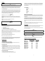
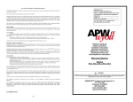
APW/WYOTT EQUIPMENT LIMITED WARRANTY
APW/WYOTT Foodservice Equipment Company warrants its equipment against defects in materials and workmanship,
subject to the following conditions:
This warranty applies to the original owner only and is not assignable.
Should any product fail to function in its intended manner under normal use within the limits defined in this warranty, at the
option of APW/WYOTT such product will be repaired or replaced by APW/WYOTT or its Authorized Service Agency. APW/
WYOTT will only be responsible for charges incurred or service performed by its Authorized Agencies. The use of other than
APW/WYOTT Authorized Service Agencies will void this warranty and APW/WYOTT will not be responsible for such work or
any charges associated with same. The closest APW/WYOTT Authorized Service Agency must be used.
This warranty covers products shipped into the 48 contiguous United States, Hawaii, metropolitan areas of Alaska and Canada. There will be no labor coverage for equipment located on any island not connected by roadway to the mainland.
IMPORTANT
FOR FUTURE REFERENCE
Please complete this information
and retain this manual for the life
of the equipment.
MODEL # ___________________________
SERIAL # __________________________
DATE PURCHASED __________________
For Warranty Service and/or Parts
this information is required
TIME PERIOD:
One-year parts, one-year labor, effective from the date of purchase by the original owner. The Authorized Service Agency
may, at their option, require proof of purchase. Parts replaced under this warranty are warranted for the unexpired portion of
the original product warranty only.
EXCEPTIONS:
*Gas/Electric Cookline - Models GCB, GCRB, GF, GGM, GGT, GHP-H, GWW, ECB, EF, EG, EHP, EWW
Three (3) Year Warranty on all component part, except switches and thermostats. (2 additional years on parts only - No labor
on second or third year.)
*Heat Strips - Models FD - Two (2) Year Warranty on element only - No labor second year.
*Glass Windows, Door Seals, Rubber Seals, Light Bulbs, Broiler Briquettes 90 Day Material Only - No labor.
In all cases parts covered by extended warranty will be shipped FOB the factory after the first year.
PORTABLE CARRY-IN PRODUCTS
Equipment weighing over 70 pounds or permanently installed will be serviced on-site as per the terms of this warranty. Equipment weighing 70 pounds or under, and which is not permanently installed i.e., with cord and plug, is considered portable and
is subject to the following warranty handling limitations.
If portable equipment fails to operate in its intended manner on the first day of connection, or use, at APW/WYOTT's option or
its Authorized Service Agency, it will be serviced on-site or replaced.
From day two through the conclusion of this warranty, portable units must be taken or sent prepaid to the APW/WYOTT
Authorized Service Agency for in-warranty repairs. No mileage or travel charges are allowed on portable units after the first
day of use. If the customer wants on-site service they may receive same by paying the travel and mileage charges.
EXCLUSIONS:
The following conditions are not covered by warranty.
*Equipment failure relating to improper installation, improper utility connection or supply and problems due to
ventilation.
*Equipment that has not been properly maintained, calibration of controls, adjustments, damage from improper
cleaning and water damaged controls.
*Equipment that has not been used in an appropriate manner, or has been subject to misuse or misapplication,
neglect, abuse, accident, alteration, negligence, damage during transit, delivery or installation, fire, flood, not or act of God.
*Equipment that has had the model number or serial number removed or altered.
PRODUCT MANUAL
Safety Instructions
Installation Instructions
Operation Instructions
Maintenance Instructions
Replacement Parts List
Warranty/Service Information
Cheese Melters
Models: CMC-24, -36, -48
CMP-24, -36, -48
CMW-24, -36, -48
If the equipment has been changed, altered, modified or repaired by other than a qualified service technician during or after
the warranty period then the manufacturer shall not be liable for any damages to any person or property which may result
from the use of the equipment thereafter.
This warranty does not cover services performed at overtime or premium labor rates. Should service be required at times
which normally involve overtime or premium labor rates, the owner shall be charged for the difference between normal service rates and such premium rates APW/WYOTT does not assume any liability for extended delays in replacing or repairing
any items beyond its control.
In all cases the use of other than APW/WYOTT authorized OEM replacement parts will void this warranty.
This equipment is intended for commercial use only. Warranty is void if equipment is installed in other than commercial application.
THE FOREGOING WARRANTY IS IN LIEU OF ANY AND ALL OTHER WARRANTIES EXPRESSED OR IMPLIED INCLUDING ANY IMPLIED WARRANTY OF MERCHANTABILITY OR FITNESS AND CONSTITUTES THE ENTIRE LIABILITY OF
APW/WYOTT IN NO EVENT DOES THE LIMITED WARRANTY EXTEND BEYOND THE TERMS STATED HEREIN.
P/N 88364-91, Revised 8/99
8
! WARNING
Improper installation, operation, service or maintenance
can cause property damage, injury or death. Read these
instructions thoroughly before installing, operating,
maintaining or servicing this equipment.
APW/WYOTT Foodservice Equipment Co.
P.O. Box 1829
Cheyenne, WY 82003
(307) 634-5801
FAX: (307) 637-8071
General Information
THIS MANUAL SHOULD BE RETAINED FOR FUTURE REFERENCE
! WARNING
CHECK THE DATA PLATE ON THIS UNIT BEFORE INSTALLATION. CONNECT THE UNIT ONLY TO THE VOLTAGE
AND FREQUENCY LISTED ON THE DATA PLATE. CONNECT ONLY TO 1 OR 3 PHASE AS LISTED ON THE DATA
PLATE.
IF THE HEATERS DO NOT COME UP TO FULL HEAT WHEN THE PRODUCT IS PLACED ON THE RACK:
1. Be sure that product is on the front half of the rack. The rack is balanced to trip the
actuating switch, but the weight must be on the front half of the rack to insure that it
does so.
2. Check that the rack is at the same level on both sides, and is correctly inserted.
3. If the rack operates freely and the heater still does not function properly, contact an
authorized service representative.
! WARNING
Improper installation, operation, service or maintenance can cause property damage, injury or death. Read these instructions
thoroughly before installing, operating, maintaining or servicing this equipment.
! WARNING
ELECTRICAL AND GROUNDING CONNECTIONS MUST COMPLY WITH THE APPLICABLE PORTIONS OF THE NATIONAL ELECTRICAL CODE AND/OR OTHER LOCAL ELECTRICAL CODES.
! WARNING
DISCONNECT ELECTRICAL POWER. SUPPLY AND PLACE A TAG AT THE DISCONNECT SWITCH INDICATING THAT
YOU ARE WORKING ON THE CIRCUIT.
Install per the spacing requirements listed in the installation section of this manual. We strongly recommend having a competent professional install this equipment. A licensed electrician should make the electrical connections and connect power to
the unit. Local codes should always be used when connecting these units to electrical power. In the absence of local codes,
use the latest version of the National Electrical Code.
Maintenance and repair should be handled by a factory authorized agent. Before doing any maintenance or repair, contact
APW/Wyott.
! WARNING
Appliance must be connected by an earthing cable to all other units in the complete installation and then to an
pendent earth connection.
inde-
NOTICE
This product is intended for commercial use only. Not for household use.
! CAUTION
The models are designed, built and sold for commercial use. If these models are positioned so the general public can use the
equipment, make sure that all cautions, warnings and operating instructions are clearly posted near each unit so that anyone
using the equipment will use it correctly and not injure themselves of harm the equipment.
! WARNING
SHOCK HAZARD
Do not open any panels that require the use of tools.
! WARNING
Improper installation, service, or maintenance can cause property damage, injury or death.
NOTICE THE UNIT, WHEN INSTALLED, MUST BE ELECTRICALLY GROUNDED AND COMPLY WITH LOCAL CODES,
OR IN THE ABSENCE OF LOCAL CODES, WITH THE NATIONAL ELECTRICAL CODE ANSI/NFPA 70-LATEST EDITION.
CANADIAN INSTALLATION MUST COMPLY WITH CSA-STANDARD C.22.2 No. 0 M1982 General Requirements - Canadian Electrical Code, Part II, 109-M1981 - Commercial Cooking Appliances.
NOTICE Local codes regarding installation vary greatly from one area to another. The National Fire Protection Association,
Inc. states in its NFPA 96 latest edition that local codes are "authority having jurisdiction" when it comes to requirements for
installation of equipment. Therefore, installations should comply with all Local codes.
PARTS LIST
DESCRIPTION
Terminal block
Cooling fan
Voltage regulator
Rack switch, 24” & 36” models
Rack switch, 48” models
Main power switch
Pilot light
Heater socket
Contactor
Wire rack, 48” models
Wire rack, 36” models
Wire rack, 24” models
Heater, 240V, 48” models
Heater, 240V, 48” Canadian models
Heater, 208V, 48” models
Heater, 208V, 48” Canadian models
Heater, 240V, 36” models
Heater, 208V, 36” models
Heater, 240V, 24” models
Heater, 208V, 24” models
Qty.
1
1
1
1
1
*
*
*
1
1
1
1
4
4
4
4
2
2
2
2
* Number required varies with unit
2
7
P/N
11072-03
12154-00
11372-02
13016-09
13016-13
13016-06
15208-00
31008-01
11195-22
31007-56
31007-80
31007-55
825301-00
825301-50
825300-00
825300-50
825332-00
825331-00
825538-00
825536-00
MAINTENANCE
! WARNING
Never clean any electrical unit by immersing it in water. Turn unit off before cleaning surface.
Congratulations on your purchase of APW/Wyott commercial cooking or refrigeration equipment. APW/Wyott takes pride in
the design and quality of our products. When used as intended and with proper care and maintenance, you will experience
years of reliable operation from this equipment. To assure best results, it is important that you read and follow the instructions in this manual carefully.
Once a week or more often if necessary clean the hotplate thoroughly. Turn off the unit and allow it to warm.
STAINLESS STEEL: To remove normal dirt or product residue from stainless steel, use ordinary soap and water (with or
without detergent) applied with a sponge or cloth. Dry thoroughly with a clean cloth. Never use vinegar or corrosive cleaner.
Do not use chorine based cleaners.
To remove grease and food splatter or condensed vapors that have baked on the equipment, apply cleaners to a damp cloth
or sponge and rub cleanser on the metal in the direction of the polished lines on the metal. Rubbing cleanser as gently as
possible in the direction of the polished lines will not mar the finish of the stainless steel. NEVER RUB WITH A CIRCULAR
MOTION. Soil and burnt deposits which do not respond to the above procedure can usually be removed by rubbing the
surface with SCOTCH-BRITE scouring pads or STAINLESS scouring pads.
! CAUTION
DO NOT USE ordinary steel wool as any particles left on the surface will rust.
NEVER USE a wire brush, steel or abrasive scouring pads (except stainless), scraper, file or other steel tools. Surfaces
which are marred collect dirt more rapidly and become more difficult to clean. Marring also increases the possibility of corrosive attack.
NEVER use any corrosive cleaner. Use only cleaners approved for stainless steel.
NEVER use cleaning solvents with a hydrocarbon base.
! WARNING
SHOCK HAZARD
De-energize all power to equipment before cleaning the equipment.
TABLE OF CONTENTS:
Safety Precautions ............................... 3
Specifications .................................... 3-4
Installation ............................................ 4
Operation.............................................. 5
Maintenance ......................................... 6
Troubleshooting.................................... 6
Parts Lists............................................. 7
Warranty............................................... 8
IMMEDIATELY INSPECT FOR SHIPPING DAMAGE
All containers should be examined for damage before and during unloading. The freight carrier has assumed responsibility
for its safe transit and delivery. If equipment is received damaged, either apparent or concealed, a claim must be made with
the delivering carrier.
A) Apparent damage or loss must be noted on the freight bill at the time of delivery. It must then be signed by the carrier
representative (Driver). If this is not done, the carrier may refuse the claim. The carrier can supply the necessary forms.
B) Concealed damage or loss if not apparent until after equipment is uncrated, a request for inspection must be made to the
carrier within 15 days. The carrier should arrange an inspection. Be certain to hold all contents and packaging material.
Installation and start-up should be performed by a qualified installer who thoroughly read, understands and follows these
instruction.
If you have questions concerning the installation, operation, maintenance or service of this product, write Technical Service
Department APW/Wyott Foodservice Equipment Company, P.O. Box 1829, Cheyenne, WY 82003.
GENERAL TROUBLESHOOTING
SAFETY PRECAUTIONS
Before installing and operating this equipment be sure everyone involved in its operation are fully trained and are aware of all
precautions. Accidents and problems can result by a failure to follow fundamental rules and precautions.
If the units fails to operate check the following:
1
Is the unit connected to a live power source?
2
Check circuit breaker?
3
Is power switch on and pilot light glowing?
4
Check the data plate. Are you operating the unit on the proper voltage?
If the above checks out and you still have problems, call an APW/Wyott authorized service agency.
NOTICE Service work should be preformed only by a qualified technician who is experienced in and knowledgeable with the
operation of commercial gas, electric, steam cooking equipment. Contact the Authorized Service Agency for reliable service,
dependable advise or other assistance and for genuine factory parts.
Warranty will be void and the manufacturer is relieved of all liability if:
(A) Service work is performed by other than an APW/Wyott Authorized Service Agency
or
(B) Other than Genuine APW/Wyott replacement parts are installed.
A current listing of all authorized APW/Wyott authorized parts/service distributors is included with this product manual at the
time of shipment. In the absence of this list you call the APW/Wyott 24 hour Service Hot Line which gives access to the
nearest Authorized APW/Wyott parts/service distributor. Call 1-800-733-2203.
TROUBLESHOOTING:
IF THE UNIT BLOWS A FUSE OR TRIPS A CIRCUIT BREAKER
1. Check the capacity of the circuit to insure that it is not overloaded, as the oven should have its own branch circuit.
2. Short circuits may be accompanied by sputtering sounds or sparks.
IF THE HEATERS DO NOT LIGHT
1. If the pilot light does not come on and the cooling fan does not run, check for a blown fuse or an open circuit breaker.
2. Check for failure of the main switch.
3. If the pilot light is lit and the cooling fan is running but the heaters do not light, call an authorized service representative.
Remember, when the unit is operating in standby, with no product on the rack, the heaters may not glow, but will still
emit some heat.
4. If one heater is lit, but the other is not, a burnout or loose connection is probable cause. Check that heater is properly
seated in its socket, then consult an authorized service representative.
The following words and symbols, found in this manual, alert you to hazards to the operator, service personnel or the equipment. The words are defined as follows:
! DANGER
This symbol warns of imminent hazard which will result in serious injury or death.
! WARNING
This symbol refers to a potential hazard or unsafe practice which could result in serious injury or death.
! CAUTION
This symbol refers to a potential hazard or unsafe practice which may result in minor or moderate injury or product or property damage.
NOTICE
This symbol refers to information that needs special attention or must be fully understood even though not dangerous.
SPECIFICATIONS – ALL 208 OR 240 VOLTS, 50-60 Hz., SINGLE PHASE .
Electrical
CMC-24 (COUNTERTOP)
CMW-24 (WALLMOUNT)
CMP-24 (PASS THRU)
CMC-36 (COUNTERTOP)
CMW-36 (WALLMOUNT)
CMP-36 (PASS THRU)
CMC-48 (COUNTERTOP)
CMW-48 (WALLMOUNT)
CMP-48 (PASS THRU)
CMC-48C (COUNTERTOP)
CMW-48C (WALLMOUNT)
CMP-48C (PASS THRU)
INPUT POWER REQUIREMENT
2.4 kW
2.4 kW
2.4 kW
3.6 kW
3.6 kW
3.6 kW
4.2 kW
4.2 kW
4.2 kW
3.4 kW
3.4 kW
3.4 kW
IF THE COOLING FAN DOES NOT RUN
1. If the pilot light is not lit and the heaters do not light, see items 1,2,3 above.
2. If the pilot light is lit and the heaters function, consult an authorized service representative.
3
6
HEATING ELEMENTS
2 AT 1200W
2 AT 1200W
2 AT 1200W
2 AT 1800W
2 AT 1800W
2 AT 1800W
4 AT 1050W
4 AT 1050W
4 AT 1050W
4 AT 850W
4 AT 850W
4 AT 850W
OVERALL DIMENSIONS:
CMC-24
CMW-24
CMP-24
CMC-36
CMW-36
CMP-36
CMC-48
CMW-48
CMP-48
WIDTH (INCHES)
27
27
27
36 1/2
36 1/2
36 1/2
48
48
48
DEPTH (INCHES)
17 1/4
17 1/4
16
17 1/4
17 1/4
16
17 1/4
17 1/4
16
HEIGHT (INCHES)
19 1/4
15 1/4
19 1/4
19 1/4
15 1/4
19 1/4
19 1/4
15 1/4
19 1/4
General Information
Clean the unit before using. Wipe body and the inside of the unit with a hot, wet cloth to remove any shipping dust or protective oil.
Electrical Connections
Check the data plate to determine what voltage this unit is wired for and what voltage service is to use.
! CAUTION
Check the data plate on this unit before installation. Connect the unit only to the voltage and frequency listed on the data plate. Connect
only to 1 or 3 phase as listed on the data plate.
! WARNING
IMPROPER GROUNDING COULD RESULT IN ELECTRICAL SHOCK
This appliance is equipped with a three-pronged (grounded) plug for your protection against shock hazard and should be plugged directly
into a properly grounded three-pronged receptacle. Do not cut or remove the grounding prong from this plug.
! CAUTION
When installed the plug for this unit should be accessible. If the power cord is damaged, replace only with an identical power cord.
Cheese Melters
These units are designed for either countertop or wallmount operation, and are also available in a passthrough version for countertop use
only. It can be used for cheese melting, finishing, glazing, or just to keep food warm. Operation is simple and automatic: just place the
product on the front of the rack—– the unit reaches full operating temperature in seconds. The degree of heating can be predetermined by
the position selected for the rack. The higher the rack, the hotter the temperature will be on the top of the product being cooked.
INSTALLATION
1. Follow General Information instructions above, making sure unit is grounded.
2. Attach legs to the countertop and passthrough models. Unit may be leveled by screwing the adjustable
bottom part of the legs in or out. (see Sketch 1.)
CAUTION: Countertop units and passthrough units must be operated with their legs in place to avoid damage
to the counter.
3. Keep the left side of the unit at least three inches from a wall or other vertical surface which would impede the
flow of cooling air into the oven. Do not place the left side of the unit near a source of heat, steam or grease.
NOTE: These units are designed to be “hard wired” for its electrical hookup. Two 1” (trade size)
Knockouts are provided at the left rear of the unit for electrician’s convenience.
A grounding lug and terminal block are under the access cover located on the left side of the unit.
WALL MOUNTING (sketch 2)
1. Begin by removing the two screws on the bottom of the unit along the rear.
2. Pry out the back at the bottom and remove it by pulling out and down.
3. Remove (but DO NOT discard) the insulation.
4. Use the back as a template to locate holes for wall attaching lag bolts( not supplied).
5. Fasten the back to the wall with lag bolts or with anchor fasteners, making certain the back is level
securely fastened.
6. Replace the insulation.
7. Hang the unit onto the wall-mounted back and secure it by replacing the two screws in the bottom of the unit.
HEATER INSTALLATION (Sketch 3)
1. Push one end of the heater into one socket as far as it will go.
2. Swing other end of heater up in line with the opposite socket.
3. Release heater and it will snap into place. Grasp the heater and move it back and forth to insure that it is centered correctly.
Choose desired rack level and insert rack by placing the left pivot point behind the switch slide, lining up the rack evenly and
pushing it straight back until the pivot points can be inserted into the rack pivots. The rack should tilt smoothly and readily
(See Sketch 4.)
4
OPERATING:
Turn on the main switch which will turn on pilot light and start fan running. Place the product on the rack.
Heaters will come on full power automatically. When the product is removed the heaters will revert to “standby”
With 25% of its heat on (A slight glow may be visible.)
and
On the 48” model, either (or both) of the two top switches must be on before the heaters will light.
The top switch is for the left side, and the middle switch is for the right side.
The amount of heat on the product may be changed by changing the rack height. The lower levels will be
Found most satisfactory for food warming. The upper levels will be useful when finishing, glazing, or cheese melting.
CLEANING:
1. Follow General Cleaning Instructions on Page 1.
2. NOTE: The heaters are self-cleaning and do not need to be washed.
DO NOT immerse them in water.
5