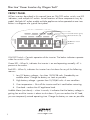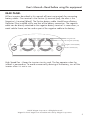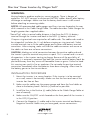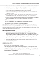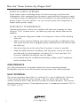
1
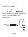
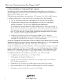
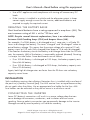
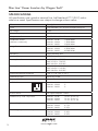
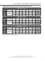
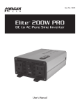
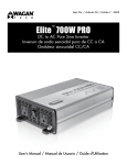
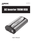
1,000 Watt: Item No. 2294 1,500 Watt: Item No. 2004 2,000 Watt: Item No. 2482 Slim Line Power Inverters ™ Input: User’s Manual 12V 24V 48V Slim Line™ Power Inverters by Wagan Tech® INTRODUCTION Thank you for purchasing a Wagan Tech ® Slim Line™ Power Inverter. With minimal care and proper treatment, it will provide years of reliable service. This User’s Manual describes the Operation, System Planning, Installation and Maintenance of four Slim Line Power Inverters. These are: 1,000W (#2294), 1,500W (#2004), and 2,000W (#2482). These three inverters are similar except for AC wattage output, DC input current, dimensions, and weight. Your Slim Line power inverter converts 12/24/48 volt battery power into 115 volts of AC power. You can use the inverter in your vehicle to operate many types of appliances that use AC power such as TV, DVD player, laptop computer, power tools, and lights for emergency or camping use. In an industry where the actual wattage output varies so greatly, Wagan Tech is proud to introduce TrueRated Power™ technology. All our inverters feature TrueRated Power. That simply means power tested and rated at a period of 24 hours continuous usage under full load. Many competing products claim “continuous duty”, when they are often only 20 minutes of “continuous” duty at full output. We also build our inverters with High Peak Surge rating to support motorized appliance start up. Read and understand this manual before installing and operating this inverter. Keep this manual for future use. 1 www.wagan.com User’s Manual—Read before using this equipment FEATURES • Two LED indicators display the operating status of the inverter. • Multiple AC outlets allow for more than one appliance to be powered at the same time. • Mounting holes allow for safe stable installation. • High Peak Power: Allows you to power appliances that require large initial start-up wattage. • Low Battery Alarm: The inverter sounds an audible alarm then turns itself off if the battery becomes too low. • Auto Shutdown/Reset Protection: The inverter temporarily shuts itself down to protect itself from overheating. • Overload/Short Circuit Protection: The inverter automatically turns itself off if the connected load is too large or if it shorts. WARNINGS • Do not attempt to open the inverter enclosure. High voltage inside the unit is the same type of power as your electrical outlets at home. • Do not operate the inverter in or around water. The voltage of the unit makes it an electrical shock hazard if operated in wet conditions. Do not let any plugged in appliance’s cord get wet. • Do not connect the AC inverter directly to another AC power source. • Keep it away from children: The inverter produces power just like AC wall outlets at home and it should be treated seriously. CAUTIONS • Do not use the inverter in a positively grounded vehicle. • Allow at least 2 inches of clearance around the inverter for air flow. • If you operate the inverter in a moving vehicle, you need to secure the inverter to prevent it from shifting around while the vehicle is moving. • If there is anything wrong with the inverter, disconnect all power. • The following operations will damage and void the warranty of the inverter: ∗∗ Reversing polarity by connecting DC cables to incorrect terminals. ∗∗ Connecting the inverter to a power source greater than 15V/30V/60V DC. ©2015 Wagan Corporation. All Rights Reserved. Wagan Tech and wagan.com are trademarks used by Wagan Corporation. 2 Slim Line™ Power Inverters by Wagan Tech® FRONT PANEL All four inverters described in this manual have an ON/OFF rocker switch, two LED indicators, and multiple AC outlets. Actual locations of these components vary by model. Multiple AC outlets enable multiple appliances to be operated at one time. Below is a diagram of a typical front panel. Vents Power On Indicator (green) AC OUTPUTS POWER OVERLOAD Overload Indicator (red) ON On/Off Power Switch AC Outlets ON/OFF Switch – Controls operation of the inverter. The below indicators operate when the switch is ON. Green LED – When lit, indicates the inverter is on and operating normally. AC is present at the outlets. Red LED – When lit, indicates the inverter has shut down for any of the following reasons: 1. Low DC battery voltage – less than 10/20/38 volts. Preceded by an audible alarm. Charge the battery as soon as possible. 2. High battery voltage – greater than 15/30/60 volts. A rare condition. 3. Over temperature − Shut off the inverter and let it cool before restarting. 4. Overload – reduce the AC appliance load. Audible Alarm (not shown) – when it sounds, it indicates that the battery voltage is getting low and the inverter is about to shut down. If you can reduce the AC load, you can temporarily extend operating time. Charge the battery as soon as possible. 3 www.wagan.com User’s Manual—Read before using this equipment REAR PANEL All four inverters described in this manual all have two terminals for connecting battery cables. One terminal is the Positive (+) terminal [red]; the other is the Negative (−) terminal [black]. The Positive battery cable should have a Battery Protection Fuse installed within one foot of the battery connection. The negative cable can be directly attached to the negative battery terminal. In some cases, a metal vehicle frame can be used as part of the negative cable to the battery. Cooling Fan Vents Cooling Fans (internally) Negative Terminal (black) Positive Terminal (red) High Speed Fan – Keeps the inverter circuitry cool. The fan operates when the inverter is powered on. To avoid unnecessarily draining of the battery, turn off the inverter when it is not in use. ©2015 Wagan Corporation. All Rights Reserved. Wagan Tech and wagan.com are trademarks used by Wagan Corporation. 4 Slim Line™ Power Inverters by Wagan Tech® MEASURING THE AC VOLTAGE This inverter’s AC output is a modified sine wave (MSW) 115 volts AC. Your household AC output is pure sine wave. The comparison of modified sine wave and household AC is shown in the figure below. (Pure sine wave) This modified sine wave has a root mean square (RMS) voltage of 115 volts. Most ordinary AC voltmeters are calibrated to read “average” voltage and assume that the AC waveform will be a pure sine wave. These meters will not correctly read MSW voltage, and will display about 20 to 30 volts too low. Any multi-meter identified as “TRUE RMS” will accurately read MSW correctly. PRODUCT USAGE FUSE 5 www.wagan.com User’s Manual—Read before using this equipment BASIC OPER ATION • Turn ON the power switch that is located at the front of the inverter, and the green LED indicator will light up as an indicator that the unit is working. • Plug your appliance(s) into the AC socket(s) at the front of the inverter. PL ANNING THE INVERTER SYSTEM Any large wattage inverter system requires planning before installation. There are several steps to the planning process so the user must determine the following: • Maximum inverter wattage required. • Operating time (run time) needed between battery recharges. • Battery bank capacity in amp-hours. • Charger requirement to charge batteries within a practical time. • Distance between battery bank and inverter. DETERMINING M A XIMUM APPLIANCE WAT TAGE Maximum AC Appliance Wattage is the first factor in planning battery and charging systems. Some background: Large microwave oven specifications list cooking power (watts) and appliance power. Appliance power is the AC load the inverter has to supply. Most other electrical tools, appliances and audio/video equipment have labels that list the unit's power requirements in watts. If the tool or device is rated in amps, multiply the amps by 115 (115V AC) to determine the watts. For example, a power tool rated at 4-amps will draw 460 watts. Determine the wattage of each appliance you need to simultaneously operate. Add all of the appliance wattages to obtain an estimated “total watts” number. Remember to consider the start-up surge that motorized appliances will cause. Do not exceed the surge rating of this inverter. This can cause immediate overload shut down. At maximum continuous output, this inverter requires a DC power supply (battery bank) that can continuously supply required amps at 12V/24V/48V DC for the duration of the run time. ©2015 Wagan Corporation. All Rights Reserved. Wagan Tech and wagan.com are trademarks used by Wagan Corporation. 6 Slim Line™ Power Inverters by Wagan Tech® CONFIGURING THE BAT TERY BANK To determine the minimum battery ampere-hour rating that you will need to operate appliances from the inverter, and any DC appliances powered by the battery bank, follow these steps: (The following calculations are specific to 12V systems. For 24V or 48V systems, a different calculation is required but the same principles should apply) 1. List the maximum continuous wattage that the inverter has to supply. 2. Estimate the number of hours the appliances will be in use between battery recharges. This will vary depending on appliances. For example, a typical home-use coffee maker draws 500 watts during its brew time of 5 minutes, but it only requires 100 watts thereafter to maintain the temperature of the pot. Similarly, a typical use of a microwave oven is only for a few minutes. Some longer operating time appliances are lamps, TV’s, computers, and refrigerator/freezers. 3. Determine the total watt-hours of energy needed. This is done by multiplying average power consumption in watts by hours of run time. For example: 1,000 watts for 10 hours = 10,000 watt hours. To get an estimate of the maximum current (in amps) that a battery bank must be capable of delivering to the inverter, divide the load watts by 10. For example a 1,000 watt appliance load will need 100 amps at 12 Volts DC. Using the 1,000 watts (or 150 Amps) for 10 hours example as above, then 100 amps is needed for 10 hours. This provides us with the basic amp-hours (AH) of battery that is required. Ten hours at 100 amps equals 1,000 Amp Hours (AH). This answer is just a beginning of configuring the battery bank because there are additional factors that determine actual run time. These include: • AC appliance load and time in use (basic AH) • Cable gage and length (cable losses) • Charge level of the batteries (between use, chargers have to be able to fully charge the batteries) • Temperature of the batteries (colder batteries provide fewer amps) • Age and condition of the batteries (older batteries lose AH capacity) • Compliance with turning off unnecessary AC loads 7 www.wagan.com User’s Manual—Read before using this equipment • Use of DC appliances and compliance with turning off unnecessary DC loads • If the inverter is installed in a vehicle and the alternator output in Amps cannot supply enough current for the inverter, additional batteries are required to supply the required current. DERATING THE BAT TERY BANK Most lead-acid batteries have a rating expressed in amp-hours (AH). The most common rating of AH is at the “20-hour rate”. NOTE: Despite several Internet explanations, here is no relationship between Cold Cranking Amps (CCA) and Ampere Hours (AH). For example, if a 20Ah battery is discharged at an 1 amp rate, is will take 20 hours to discharge that battery. The terms “charged” and “discharged” relate to actual battery voltage. This means that the output voltage of a nominal 12 volt battery starts at 13.2 volts (fully charged) then drops to 10.6 volts (discharged). If the load on the battery causes the battery to discharge faster than the 20 hour rate, the capacity (AH) of the battery is measurably reduced (derated). Derating is a major run time factor. Some benchmarks are as follows: • If an 100 Ah Battery is discharged at 100 Amps, the battery capacity acts like a 56 Ah battery. • If an 100 Ah Battery is discharged at 200 Amps, the battery capacity acts like a 32 Ah battery. Again, both high discharge rates are faster than the 20-hour rate so battery capacity seems lower. INSTALL ATION Safe installation requires that a Battery Protection fuse is installed within one foot of the positive (+) battery Terminal [red]. Use ANL marine fuses or equal because they do not spark when they blow. Use an appropriate fuse holder for the fuse. ANL fuse holders can be mounted so they do not move in a vehicle or vessel. CONNECTING THE INVERTER Loose DC (battery) connections will result in a severe voltage drop that can cause damage to connectors, conductors, and insulation and can cause sparking. Reverse polarity connection can permanently damage to the inverter. Damage caused by reverse polarity will void the warranty. ©2015 Wagan Corporation. All Rights Reserved. Wagan Tech and wagan.com are trademarks used by Wagan Corporation. 8 Slim Line™ Power Inverters by Wagan Tech® WARNING: Venting batteries produce explosive, corrosive gases. There is danger of explosion. DO NOT connect or disconnect BATTERY cables directly after battery discharge or recharge. Make sure that the battery bank area is well vented before attaching or removing cables. NOTES: All recommended cable gauges and fuse sizes are located at the rear of this manual in the Cable Gauge Table. The table describes Cable Gauges for lengths greater than supplied cables. “Round Trip” refers to actual cable distance in feet from the POS (+) battery terminal through the inverter and back to the NEG (−) battery terminal. Crimp-on ring terminals are required on all cable ends. The cable ends need to be stripped of insulation for 1/2 inch before crimping on ring terminals. Select a crimp terminal size to fit the cable gauge and inverter and battery terminal connectors. After crimping, make sure that the cable connectors are secure on the cables so there are no loose connections. CAUTION: Making an initial connection between the positive cable end and the inverter’s positive terminal may cause a spark. This is normal and is a result of capacitors in the inverter starting to charge. Because of the possibility of sparking, it is extremely important that both the inverter and the battery bank be positioned away from any source of flammable fumes or gases. Failure to heed this warning can result in fire or explosion. Do not make the positive terminal connection immediately after the batteries have been charging. Allow time for the battery gasses to vent to outside air. INSTALL ATION PROCEDURE 1. Mount the inverter in a secure location. If the inverter is to be mounted on a wall, mount it horizontally. Make sure that the front and rear of the inverter has free air flow. 2. Make sure the cables are the proper gauge and have the fuse holder as close to the battery bank’s Positive (+) terminal as possible. 3. Install the fuse in the Positive (+) cable (Refer to the Cable Gauge Table at rear of manual). 4. Make sure the ON/OFF switch located on the front panel of the inverter is in the OFF (O) position. 5. Connect the Negative (−) cable end to the inverter terminal and battery Negative Terminal. Make sure you have good, secure connections. 9 www.wagan.com User’s Manual—Read before using this equipment 6. Recheck and make sure the DC cable fuse is installed in the fuse holder. 7. Attach the positive cable to the Positive (+) DC connector on the battery and then the inverter. Make sure the connections are tight and secure. 8. Turn on the inverter from the Front Panel ON/OFF Switch. 9. Make certain that the green Operating LED is lit and the red FAULT LED indicator is not lit. 10.Turn OFF (O) the inverter. The Fault LED may briefly flash; this is normal. The audible alarm may also sound a short chirp; this is also normal. 11.When you have confirmed that the appliance to be operated is turned off, plug the appliance into one of the AC outlets on the inverter. 12.Turn the inverter on. 13.Turn the appliance on. The appliance should begin working. 14.Observe the LED indicators for normal operation. If flooded lead acid batteries are used, be sure that periodic checks of battery electrolyte levels are accomplished. Follow battery manufacturer’s instructions in keeping the electrolytes at the proper level. Be sure to use pure distilled water when replacing evaporated electrolyte liquid. RECOMMENDATIONS • If the power inverter makes a beeping sound, turn OFF the inverter, disconnect all appliances from the inverter and disconnect the inverter from the power supply. The beeping sound is the low battery warning that indicates that the voltage of the battery power supply is getting low. Please restart the vehicle engine to charge the battery before using it to operate the inverter again. • When you are not using the inverter, turn the power switch to OFF. This conserves battery power. OPER ATING TIPS ADDING AN EXTENSION CORD If you need an extension cord, we recommend the use of an extension cord between the AC output of the inverter and the AC appliances. You may use up to 100 feet of high quality, heavy-duty extension cord. A longer cord will result in reduced power to appliances. ©2015 Wagan Corporation. All Rights Reserved. Wagan Tech and wagan.com are trademarks used by Wagan Corporation. 10 Slim Line™ Power Inverters by Wagan Tech® BUZZ IN AUDIO SYSTEMS Some stereo systems and boom boxes will emit a buzzing noise from their loudspeakers when operated from the power inverter because the power supply in the device does not adequately filter the modified sine wave produced by the power inverter. The only solution is to use a sound system that incorporates a higher quality power supply. TELEVISION INTERFERENCE Operating the power inverter can interfere with television reception on some channels. If this situation occurs, the following steps may help to alleviate the problem: • Do not operate high power loads with the power inverter while watching television. • Make sure the antenna feeding your television provides an adequate staticfree signal and you are using good quality cable between the antenna and the television. • Move the television as far away from the power inverter as possible. • Keep the cables between the battery and the power inverter as short as possible and twist them together with about 2 to 3 twists per foot. This minimizes radiated interference from the cables. • Ferrite beads may be installed around battery cables and AC appliance cords to reduce noise. MAINTENANCE Very little maintenance is required to keep the inverter operating properly. Periodically check to ensure all terminals and connectors are secure and tight. HEAT DISPERSAL The inverter generates heat while it is working. This is not a malfunction. However, if the inverter gets too hot while working, it will turn off by itself. Position the inverter where air flows freely around it to allow the heat to disperse. The inverter’s thermal protection prevents it from operating when its temperature exceeds 130ºF ± 10ºF (55ºC ± 5ºC). 11 www.wagan.com User’s Manual—Read before using this equipment TROUBLESHOOTING PROBLEM: Low or No Output Voltage – Fault LED Lit Reason Solution Poor contact with battery or inverter terminals. Clean terminals thoroughly. Reinstall and tighten. PROBLEM: Inverter Automatically Shut Down – Fault LED Lit Reason Solution Battery voltage below 10/20/38 Volts Charge or replace battery. Inverter is too hot. (Thermal protection mode.) Allow inverter to cool. Check for adequate ventilation. Reduce the load on the inverter to rated continuous power output. Unit may be defective. See warranty and call customer service. PROBLEM: Inverter Automatically Shut Down – Fault LED Lit – OVL Display Reason Solution Equipment being operated draws too much power. Use a higher capacity inverter or do not use this equipment. PROBLEM: Continuous Buzzing Sound – Display Shows Low Voltage Reason Solution Input voltage below 10.5/21.0/42.0 Volts. Keep input voltage above 10.5/21.0/42.0 Volts Poor or weak battery condition. Recharge or replace battery. Poor or loose cable connection. Inspect terminals and tighten all connections. Inadequate power being delivered to the inverter or excessive voltage drop. Use heavier gauge DC cable. Keep cable length as short as possible. DISPOSAL/RECYCLING OF INVERTER Electronic products are known to contain materials that are toxic if improperly disposed. Contact local authorities for disposal and recycling information. ©2015 Wagan Corporation. All Rights Reserved. Wagan Tech and wagan.com are trademarks used by Wagan Corporation. 12 Slim Line™ Power Inverters by Wagan Tech® SPECIFICATIONS All specifications are typical at nominal line, half load and 77ºF (25ºC) unless otherwise noted. Specifications are subject to change without notice. 13 Name Description Input 12V/24V/48V (10–15V/20–30V/40–60V) DC AC Output 115V Output frequency 60 Hz Output waveform Modified Sine Waveform TrueRated™ Power (24-hour continuous) Item No. 2294: Item No. 2004: Item No. 2482: 1,000 Watts 1,500 Watts 2,000 Watts Surge Power Item No. 2294: Item No. 2004: Item No. 2482: 2,500 Watts 3,500 Watts 4,000 Watts Efficiency Approximately 90% No load current < 0.95 Amps Battery low alarm 12V: 10.5V ± 0.5V DC 24V: 21.0V ± 1.0V DC 48V: 42.0V ± 2.0V DC Battery low shutdown 12V: 10.0V ± 0.5V DC 24V: 20.0V ± 1.0V DC 48V: 38.0V ± 2.0V DC Alarm and thermal shutdown 130 ºF ± 10º (55 ºC ± 5º) Internal DC fuse Varies by model External DC fuse None AC Outlets Item No. 2294:3 Item No. 2004:3 Item No. 2482:2 Power switch DC input ON/OFF control Dimensions (L x W x H) inches Item No. 2294:10.3 × 5.4 × 2.5 Item No. 2004:12.3 × 5.4 × 2.1 Item No. 2482:12.3 × 6.5 × 3.0 Gross Weight Item No. 2294: Item No. 2004: Item No. 2482: 3.5 lb 4.1 lb 5.2 lb Net Weight (includes cables) Item No. 2294: Item No. 2004: Item No. 2482: 4.6 lb 5.4 lb 6.9 lb www.wagan.com User’s Manual—Read before using this equipment CABLE GAUGES BASED ON ROUND TRIP CABLE LENGTHS 1,000W (Item No. 2294) Input Cable length (feet) 12V 24V Gauge (AWG) 48V 8 9–10 11–14 15–17 18–21 22 23–25 Fuse* (Amps) 6 4 2 2 2 0 0 120 8 6 4 4 4 2 2 60 10 8 6 6 6 4 4 30 18–21 22 23–25 Fuse* (Amps) 1,500W (Item No. 2004) Input Cable length (feet) 12V 24V Gauge (AWG) 48V 8 9–10 11–14 15–17 4 2 2 0 0 0 00 200 6 4 4 2 2 2 0 100 8 6 6 4 4 4 2 50 2,000W (Item No. 2482) Input Cable length (feet) 12V 24V 48V Gauge (AWG) 8 9–10 11–14 15–17 18–21 22 23–25 Fuse* (Amps) 2 2 0 0 00 000 000 250 6 4 2 2 0 0 0 120 6 6 4 4 2 2 2 60 *Battery protection fuse not included. ©2015 Wagan Corporation. All Rights Reserved. Wagan Tech and wagan.com are trademarks used by Wagan Corporation. 14 WAGAN Corp. Limited Warranty The WAGAN Corporation warranty is limited to products sold only in the United States. Warranty Duration: Product is warranted to the original purchaser for a period of one (1) year from the original purchase date, to be free of defects in material and workmanship. WAGAN Corporation disclaims any liability for consequential damages. In no event will WAGAN Corporation be responsible for any amount of damages beyond the amount paid for the product at retail. Warranty Performance: During the warranty period, a product with a defect will be replaced with a comparable model when the product is returned to WAGAN Corporation with an original store receipt. WAGAN Corporation will, at its discretion, replace or repair the defective part. The replacement product will be warranted for the balance of the original warranty period. This warranty does not extend to any units which have been used in violation of written instructions furnished. Warranty Disclaimers: This warranty is in lieu of all warranties expressed or implied and no representative or person is authorized to assume any other liability in connection with the sale of our products. There shall be no claims for defects or failure of performance or product failure under any theory of tort, contract or commercial law including,but not limited to negligence, gross negligence, strict liability, breach of warranty, and breach of contract. Returns: Please contact customer service by phone, email, or visiting our website under "Customer Care" page for instructions on how to process a warranty claim. WAGAN Corporation is not responsible for any shipping charges incurred in returning the item(s) back to the company for repair or replacement, nor is WAGAN responsible for any item(s) returned without an official Return Authorization number (RA#). Register your product online at http://tinyurl.com/wagan-registration to be added to our email list. You will receive previews on our upcoming products, promotions, and events. ©2015 31088 San Clemente Street Hayward, CA 94544, U.S.A. US & CAN Toll Free: +1.800.231.5806 Tel: + 1.510.471.9221 [email protected] www.wagan.com ©2015 Wagan Corporation. All Rights Reserved Wagan Tech and wagan.com are trademarks used by Wagan Corporation REV20150421-E