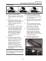
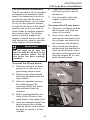
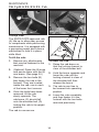
1
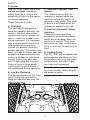
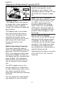
SR-70/SR-80
Rubber Track Loaders
P
O S I -
T
R A C K
SR-SERIES
Operation and Maintenance Manual
INTRODUCTION
Thank you for purchasing an ASV Rubber Track Loader. With
this machine, you will be able to perform tasks faster and more efficiently than with any other machine its size.
The SR-70/80 are rugged and agile machines capable of working on
a variety of challenging terrains. They are designed to be very safe,
but safe operation also requires caution and attentiveness on the
part of the operator.
There are many hazards that can be encountered during operation
of an off highway utility vehicle such as the SR-70/80. With this in
mind, it is the responsibility of each operator to read and fully understand this manual before attempting to operate the machine.
Machine damage, bodily injury, or even death may result if the procedures and precautions described in this manual are not followed
closely.
FRONT
Machine Orientation
Terms like front, rear, left,
and right are used throughout this manual to describe
portions of the machine.
They are to be understood
from the perspective of an
operator seated inside the
cab.
LEFT
RIGHT
REAR
1
SAFETY OVERVIEW
SAFETY SYMBOL
!
This symbol means: Attention! Be alert!
Your safety is involved!
A safety message will follow this symbol
describing the hazard and the precautions
that need to be taken to ensure your safety.
Read and understand all safety messages in order to protect yourself and others from personal injury or death.
These safety messages are identified by the words:
DANGER, WARNING, and CAUTION.
DANGER
“DANGER” refers to an imminently hazardous situation that may
result in serious injury or even death.
WARNING
“WARNING” refers to a potentially hazardous situation that may
result in serious injury or even death.
CAUTION
“CAUTION” refers to a potentially hazardous situation that may result
in damage to the machine or its components.
The word “Note” is used throughout this manual to draw your
attention to specific topics or to supplement the information
provided in that section.
It is not possible to anticipate every potential hazard. The safety
messages included in this document and displayed on the machine
are not all-inclusive. They are intended to make you aware of potential risks and encourage a safe approach to operation, inspection
and maintenance of the machine. Do not operate the machine until
you are sure you have a thorough understanding of its operation,
inspection and maintenance. It is your responsibility as the operator
to exercise caution while performing these tasks to ensure your
safety and the safety of others.
WARNING
Read and understand this manual prior to operating, inspecting, or
attempting to maintain the Rubber Track Loader. Performing any of
these tasks incorrectly can lead to machine damage, personal injury
or even death.
2
MACHINE IDENTIFICATION
Serial Numbers
Manual Storage
Product ID Number
The Machine PIN is located on
the front of the cab near the
lower right corner of the door
opening. This number must be
provided when contacting your
dealer regarding parts, service,
warranty or accessories.
Warranty claims will not be
processed unless the machine
PIN is provided.
The manual storage compartment is located in the lower left
portion of the cab near the operator’s left leg.
Engine Serial Number
The Engine serial Number is
located on a metal identification
plate fastened to the engine
valve cover at the rear of the
machine.
3
TABLE OF CONTENTS
Introduction ....................................... 1
Safety Overview ................................ 2
Machine Identification.................... 3
Safety ............................................................... 6
Controls .............................................................. 14
Operation........................................................... 22
Maintenance ..................................................... 32
Troubleshooting.............................................. 58
Machine Specifications................................. 63
Limited Warranty............................................. 64
Standard Torque Guidelines ....................... 65
Recommended Fluids ................................... 66
Service Log ........................................................ 67
4
5
SAFETY - CONTENTS
Features .............................................................. 7
Tipping Load/Operating Cap./GVW ......... 9
Fire Prevention................................................. 10
Warning Decals................................................ 11
6
SAFETY
Features
The SR 70/80 rubber track loaders are equipped with many
safety features to reduce the
possibility of injury to the operator during operation.
C. Operator Presence Seat
Switch
This switch ensures that the
operator is seated inside the
machine before any motion is
allowed to take place. This safety switch is activated when an
operator is seated in the cab.
These features include:
A. Seat Belt
The seat belt is designed to
keep the operator securely fastened in the seat should the
machine encounter uneven terrain or come to a sudden stop
during operation. It is equipped
with a safety switch that is activated when the seat belt is
clicked into position around a
seated operator. This switch has
been included to ensure that the
seat belt is fastened before any
motion is allowed to take place.
Always fasten your seat belt
prior to operating the machine.
Serious injury or even death
could result if your seat belt is
left unfastened during operation.
D. Auxiliary Hydraulic Safety
Switches
These switches have been
included to ensure that attachments do not engage when the
machine is started. They must
be locked into their neutral positions in order for the machine to
start.
E. Parking Brake
The SR 70/80 are equipped with
parking brake mechanisms. The
brake effectively locks the transmission when activated to prevent machine movement.
Note: The lift arm control will still
function normally when the parking brake is active.
B. Lap Bar Restraint
The lap bar restraint acts in conjunction with the seat belt to
keep the operator securely fastened in the seat.
D
E
B
A
C
7
SAFETY
Features
F. Power Quick-Attach Safety
Switch (if equipped)
The purpose of this switch is to
ensure attachments are properly
fastened to the machine prior to
operation. The engine will not
start unless this switch is in the
locked position. When installing
an attachment, always perform a
visual check to make sure it is
correctly attached and locked in
place prior to use.
Note: Items D and F are
equipped with small orange locking devices. In order to move
these switches, you must first
disengage the locking devices
by sliding them downward. The
switches may then be moved
into the desired positions.
G. Lift Arm Brace
Each machine is equipped with
a brace to ensure your safety
during service work or maintenance. Prior to performing any
service or maintenance that
requires the lift arms to be in the
raised position, follow the lift arm
brace installation procedure
located on page 34.
F
8
H. Escape Hatch
The rear window on the SR70/80 serves as an escape
hatch in an emergency situation.
It is identified by a yellow triangular tag attached to the rubber
molding surrounding the window.
To exit through this opening,
grab hold of the tag and pull to
remove the molding. This will
allow the window to be pushed
out. Then carefully crawl out of
the opening to safety.
G
H
SAFETY
Tipping Load/Operating Capacity/GVW
Load
C of G
Tipping Load
The tipping load is the amount
of weight that, when applied to
the bucket center of gravity,
causes the machine to begin tipping forward.
The tipping load is calculated
with the machine still and on
level ground, equipped with a
standard dirt bucket that is
raised to the point in the lift arm
path where the load is positioned furthest from the
machine.
Rated Operating Capacity
The rated operating capacity
(ROC) is a percentage of the tipping load. The ROC is equal to
35% of the tipping load for traditional track loaders, or 50% of
the tipping load for wheeled skid
steer loaders. ASV publishes
both the 35% and the 50% rating for reference and comparison.
Doing so could result in serious
injury to the operator and or
damage to the machine. The
operating capacity ratings for the
SR-70/80 are located on page
63.
Note: SAE J818 standards
define operating capacity ratings
for rubber tired skid steer loaders (50% tipping load) and
tracked loaders (35% tipping
load). There are no standards
defining the operating capacity
of machines equipped with suspended undercarriages or rubber tracks.
Gross Vehicle Weight
The G.V.W. of the SR-70 and 80
machines should never exceed
11,500Lbs. for the SR-70 and
12,500 lbs. for the SR-80 during
operation. This weight excludes
an operator, but does include
any accessories, attachments or
material being moved.
Operating the machine in excess
of the the G.V.W. will void the
warranty.
The ROC applies only to the
bucket attachment. Pallet forks
or other attachments often move
the center of gravity further
away from the machine reducing
the ROC.
Do not exceed the rated operating capacity for your machine.
9
SAFETY
Fire Prevention
Fire Prevention
Precautionary Tasks:
Rubber Track Loaders have
components that operate at high
temperatures. Steps must be
taken to make sure that flammable items are kept clear of these
components during operation.
Failure to do so may result in a
fire.
• With the engine off and cool,
remove any debris present in
the engine compartment and
chassis area (under cab).
Remove the belly pans and
pressure wash these areas
to clean them properly.
• Check the battery, fuse box,
electrical wiring and connection points for damage or
looseness.
• Check fuel lines for leaks or
damage. Never allow open
flame near fuel or fuel system
components.
• Check hydraulic lines, hoses
and fittings for damage or
leaking fluid. Never use bare
hands to check for leaks.
Pressurized fluid can penetrate skin and cause injury or
even death.
The main heat sources in the
vehicle are the engine and the
exhaust system. The electrical
system could also be a source
of heat/sparks if damaged or
poorly maintained.
In some work environments,
flammable items such as leaves,
straw and brush cutting debris
may come in contact with these
sources. It is very important that
these flammable items be
removed often from areas close
to hot components. If debris is
allowed to accumulate, a fire
may result posing a risk to the
operator and the machine. A fire
can cause machine damage,
severe injury or even death.
Listed are a set of precautionary
tasks that should be performed
daily or more often if necessary.
Repair or replace worn or damaged components as needed to
ensure safe machine operation.
10
WARNING
• Do not use ether or any other
aerosol type starting aid to
start the engine.
• Always stop the engine and
allow the machine to cool
prior to adding fuel.
• Do not smoke or allow open
flame near the machine while
refueling.
SAFETY
Warning Decals
There are decals positioned throughout the machine to warn operators of potential hazards. They must be observed and obeyed to
avoid risks of machine damage, personal injury or even death. They
are displayed here along with supplementary graphics that help to
illustrate their intent and significance.
Entering and Exiting
Carrying Loads / Inclines
Riders
Work Platform
11
SAFETY
Warning Decals
Operating Position
12
13
CONTROLS - CONTENTS
Instrument Display ......................................... 15
Switch Panels.................................................... 16
Drive & Lift Arm .............................................. 17
Throttle/Electric Attachment...................... 18
Auxiliary Hydraulic.......................................... 19
Two Speed/Power Quick Attach................ 21
14
CONTROLS
Instrument Display
B
C
A
D
E
G
H
I
J
F
There are many instruments
involved in the safe operation of
your machine. Make sure to
learn the location, and function
of each of these items prior to
operating your machine.
Instrument Display
The instrument display has been
configured for visibility and
ergonomic function.
The display includes:
A. Engine Temperature Gauge
B. Oil Pressure Gauge
C. Fuel Gauge
D. Hydraulic Oil Temp. Gauge
E. Voltmeter
F. Tachometer
G. High Range Indicator
H. Glow Plug Operation Indicator
I. Low Range Indicator
J. Parking Brake Indicator
K. Hour Meter
K
The glow plug operation light
should illuminate only when the
ignition switch is turned to the
pre-heat position.
Pay close attention to the display during operation to ensure
that all systems are functioning
properly.
15
CONTROLS
Switch Panels
Left
Right
O
L
P
M
Q
N
Switch Panels
There are three main panels which
house the switches used to control
various functions throughout the
machine.
The switch panels include:
L. Parking Brake Switch
M.Headlight Switch
N. Bucket Positioning Switch
O. High Flow Aux. Switch
P. Low Flow Aux. Switch
Q. Hyd. Quick Attach Switch*
R. Heater Fan Switch**
S. Windshield Wiper Switch**
T. Beacon Switch**
U. Ignition Switch
R
S
T
U
* Optional on SR 70
** Optional on SR 70/80
16
CONTROLS
Drive & Lift Arm
Drive Control
Lift Arm Control
The SR-70/80 are equipped with
pilot operated joystick controls.
The drive control (left joystick) is
used to control track motion. The
illustration above shows the relationship between joystick and
machine movement.
The lift arm control (right joystick) is used to control the lift
arms and attachment (bucket)
movement. The illustration
above shows the relationship
between joystick and lift
arm/attachment movement.
Note: The machine will not
move as long as the drive control is in the neutral position.
Each joystick is equipped with a
spring return feature that automatically returns it to neutral
position when released.
The SR-70/80 are equipped with
a float function that allows the lift
arms and attachment (bucket) to
follow the contours of the ground
as you move with only their own
weight acting as downforce.
To stop a moving machine,
release the left joystick altogether. This will stop the machine.
• To engage: push the joystick
fully forward into position.
(see illustration)
• To disengage: pull back
quickly on the joystick.
17
CONTROLS
Throttle/Electric Attachment
Throttle Controls
Electric Attachment Control
The throttle controls engine
RPM. When performing work
that requires delicate, precise
movements, use a lower RPM.
When more speed, horsepower,
or flow is required, use a higher
RPM.
Most attachments for ASV
Rubber Track Loaders are controlled hydraulically, but some
require electrical input as well.
When electrical input is required,
the four buttons on the drive
control (left) joystick can be utilized to send electrical current to
the receptacle located on the
upper left side of the lift arms.
The SR 70/80 are equipped with
foot operated throttle mechanisms.
• To increase engine RPM,
press the front (toe) of the
foot pedal slowly towards the
floor until the desired rpm has
been reached.
Note: ASV receptacle style and
pin designation may differ from
those utilized by other manufacturers. To ensure proper function, use only ASV approved
attachments.
• To decrease RPM, press the
rear (heel) of the pedal
towards the floor.
Throttle
Buttons
18
CONTROLS
Auxiliary Hydraulic
The SR70/80 are equipped with
high and low flow auxiliary
hydraulic circuits that allow for
the use of hydraulic attachments.
The couplers for the auxiliary circuits are located on the left side
of the lift arms near the front of
the machine. They are positioned from top to bottom as
such: (see photo)
A.
B.
C.
D.
E.
Note: Low and high flow circuits
may not be used simultaneously.
Low Flow Intermittent
The low flow auxiliary circuit can
be utilized intermittently or continuously. It also has the capability of varying attachment speed
through the use of a spring centered roller switch (F) located on
the back of the right joystick.
F
Case drain
High flow
High flow
Low flow
Low flow
A
B
C
D
E
The SR-70/80 uses a variable
displacement pump to supply oil
to the low and high flow auxiliary
circuits. This pump displaces
30gpm when the high flow
switch is activated and 20gpm
when the low flow switch is activated.
To prevent an operator from
accidentally sending 30gpm
through a low flow attachment,
the machines are equipped with
a switch mechanism that disables the high flow switch when
an attachment is connected to
the low flow quick couplers.
Attachment direction is determined by rolling the switch to the
right or left or center. Attachment
speed is determined by the
amount that it is rolled in the
chosen direction. This variability
gives the operator more control
over the actuation speed of the
attachment.
To activate the low flow auxiliary
hydraulic circuit intermittently,
roll the switch left or right of center.
• To pressurize the upper low
flow quick coupler, roll the
switch to the left of center.
• To pressurize the lower low
flow quick coupler, roll the
switch to the right of center.
• To de-activate low flow intermittent operation, release the
variable switch and flow will
cease.
19
CONTROLS
Auxiliary Hydraulic
Low Flow Continuous
To activate the low flow auxiliary
hydraulic circuit continuously,
depress the rocker type switch
located on the switch panel. (H)
• To pressurize the upper low
flow quick coupler, press the
top of the switch.
• To pressurize the lower low
flow quick coupler, press the
bottom of the switch.
• To de-activate low flow continuous operation, move the
switch into the middle (neu
tral) position.
High flow
To activate the high flow auxiliary hydraulic circuit, depress the
rocker type switch located on
the switch panel. (G)
• To pressurize the upper high
flow quick coupler, press the
top of the switch.
• To pressurize the lower high
flow quick coupler, press the
bottom of the switch.
• To de-activate high flow continuous operation, move the
switch into the middle (neutral) position.
Note: When connected to an
attachment, the auxiliary switches have the effect of reversing
flow through their respective circuits when switched or rolled
from one position to the other.
20
G
H
Note: The high and low flow
auxiliary hydraulic switches are
equipped with locking devices.
Their purpose is to lock the
switches into neutral position
when not in operation. These
locking devices must be disengaged prior to use. To disengage, slide the locking device
downward. The switch can then
be moved into position.
CAUTION
It is very important to match
G.P.M. ratings when utilizing
attachments. If you use an
attachment that is rated for more
G.P.M. than is available in an
auxiliary circuit, attachment performance will suffer. If you use
an attachment that is rated for
less G.P.M. than is available in
an auxiliary circuit, you will
overheat your hydraulic system
and most likely damage your
machine/attachment. ASV recommends using only attachments that are designed to work
with your specific machine.
CONTROLS
Two Speed/Power Quick Attach
Two Speed
Power Quick Attach
The SR 80 is equipped with a
two speed drive system with low
and high range.
The SR machines are available
with a power quick attach feature that allows the operator to
fasten and unfasten attachments
without exiting the machine.
(SR-80-standard/SR-70-optional)
• Low range is best suited to
performing strenuous tasks or
running attachments.
• High range is intended
primarily for transporting.
To activate high range, press the
button on the front of the right
joystick. To return to low range,
press the button a second time.
There is a high/low range indicator light located in the instrument
display to confirm which range
you are operating in.
Note: When shifting between
ranges, slow the machine down
to ensure a smooth transition.
• To lock the power quick
attach, depress the rocker
type switch located on the
switch panel into the lock
position.
• To unlock the quick attach,
move the switch to the unlock
position.
Note: The power quick attach
switch is equipped with a locking
device. The device must be disengaged in order to unlock the
quick attach. To disengage, slide
the locking device downward.
The switch can then be moved
into the unlocked position.
21
OPERATION - CONTENTS
Pre-Operation................................................... 23
Starting Procedure ......................................... 24
Operation Techniques ................................... 25
Attachments ..................................................... 29
22
OPERATION
Pre-Operation
Pre-Operation Safety Check
Before operating the machine,
perform a pre-operation safety
check. Inspect the machine for
any items that may affect safe
operation.
Check to make sure:
1. Engine compartment, chassis and coolers are clean
and free of debris. (see
page 39)
Note: The parking brake is automatically activated when the
operator removes the seat belt
or leaves the operator seat.
Note: The parking brake should
be manually activated when
using an attachment that
requires the machine to remain
stationary during operation.
2. Windows and lights are
clean and unobstructed.
3. Tracks are in good working
condition.
4. Track tension is adjusted
correctly.
Correct
5. All fluids are filled to appropriate levels.
6. Battery cables are in good
condition and securely fastened.
7. Accessory belts are in good
condition and properly tensioned.
8. Hydraulic hoses and fittings
are in good condition. (No
visible wear or leaks)
9. Joysticks and high/low flow
auxiliary switches are in their
neutral positions.
10. Power quick attach is in
locked position. (if equipped,
visually verify)
Incorrect
WARNING
Entering or exiting the machine
under raised lift arms can cause
serious injury or even death.
Never allow anyone to go
beneath unsecured lift arms.
11. Hood is closed and
bystanders are clear of any
moving parts.
12. All grease points have been
lubricated.
23
OPERATION
Starting Procedure
Starting Procedure
Upon completion of the preoperation safety check, if all
items are in compliance, you are
ready to start your machine.
To start the machine:
1. Enter the machine (lift arms
in lowered position) from the
front while maintaining at
least 3-point contact with the
machine at all times to
ensure your safety. (2hands, one foot or viceversa)
2. Sit down into the operator
seat, fasten the seat belt
securely around your lower
abdomen and pivot the
lap bar restraint into position.
3. From the SLOW position,
move the throttle to 1/3 open
by pressing the foot pedal
forward approximately 1/3 of
its travel.
4. Insert the key into the ignition switch and turn it to the
left for approximately 6 seconds to pre-heat the engine.
During this time, the glow
plug operation light will
illuminate.
5. Once the engine has been
pre-heated, turn the key to
the right and hold to start the
engine. Release the key as
soon as the engine fires.
24
6. Once running, reduce throttle to a low idle by pushing
back slowly on the foot
pedal with your heel. Allow
the engine to idle for 3-5
minutes to reach operating
temperature.
7. Once the engine has
reached operating temperature, set desired RPM by
moving the foot pedal into
position.
The machine is now ready for
operation.
WARNING
Failure to fasten your seat belt
could result in serious injury or
death.
WARNING
Do not use aerosol type starting
aids such as ether. Explosion
may result.
CAUTION
Do not crank the engine for
more than 20 seconds. Allow
the starter to cool for two minutes before cranking again.
OPERATION
Operation Techniques
Operating Your Machine
Dirt Work
Operating an ASV Rubber Track
Loader is intended to be as safe
and simple as possible. The
controls section of this manual
covers the various controls used
to operate the machine. Each
operator should take the time
necessary to familiarize him/herself with the controls section
prior to attempting to operate the
machine.
ASV Rubber Track Loaders provide far superior traction and
floatation than traditional
wheeled loaders. This added
capability enables an operator to
fill the bucket by slowly driving
into a pile of dirt without having
to depend on vehicle momentum
to plunge into the pile.
This section covers safe operation procedures and some basic
do’s and don'ts to keep in mind
while operating the machine. In
order to learn to properly operate the machine, it is very important that each operator read and
understand this manual thoroughly. It is also very important
to take the time necessary to
become skilled in operation
techniques in accordance with
the instructions in this section.
Do this in an open area that is
free of potential hazards and
bystanders. This will give the
operator space to practice without worry of injuring people or
damaging property including
him/herself and the machine.
Machine weight is more evenly
distributed throughout the chassis with this design providing
significantly more down pressure
at the front of the machine than
traditional wheeled loaders. The
result is improved cutting and
back dragging performance without the need to force the front of
the machine off of the ground.
CAUTION
Pushing the front of the
machine off of the ground with
the bucket or attachment will
reduce traction and machine
component life.
The lift arms are meant to rest
against the frame while digging
or grading. Utilizing your
machine in this manner will minimize stress on components and
maximize machine performance
and efficiency.
25
OPERATION
Operation Techniques
Filling The Bucket
Steps: (see illustration)
1. Lower the lift arms until they rest on the frame.
2. Tilt the bucket slowly forward until the cutting edge engages
the ground.
3. Drive the machine forward until the bucket is full of material.
4. Curl the bucket and raise the lift arms simultaneously to
break the load free from the pile.
5. Maneuver the machine clear of the pile and then lower the lift
arms, keeping the bucket curled upward, to approximately 1012” above the ground for transporting.
Grading
Steps: (see illustration)
1. Lower the lift arms until they rest on the frame.
2. Tilt the bucket slowly forward until the cutting edge engages
the ground.
3. Drive the machine forward making slight bucket angle adjustments to vary cut depth as necessary.
4. When full, curl the bucket and raise the lift arms simultaneously.
Once clear, lower them to approximately 10-12” above the
ground for transporting.
CAUTION
Do not push or pull dirt as done in digging, grading, or leveling operations with the bucket tilted fully forward into the “Dump” position.
This will stress the bucket cylinders and may damage them.
26
OPERATION
Operation Techniques
Leveling
Steps: (see illustration)
1. Moving forward, raise the lift arms as you tilt the bucket slowly
forward to evenly spread the material out over the ground.
2. Once the load is released, tilt the bucket forward to an angle
45° or less to the ground.
3. Lower the lift arms until the cutting edge rests on the ground.
4. Engage the float function and back the machine over the material varying bucket angle slightly as necessary to maintain grade.
Loading
Steps: (see illustration)
1. Engage the self level (bucket positioning) function, then raise
the lift arms upward until the bottom of the bucket clears the side
of the truck bed or trailer.
2. Once clear, drive the machine forward until the pivot point of the
bucket clears the bed side.
3. Tilt the bucket forward until all of the material has been
released into the bed.
Note: It may be necessary to quickly tilt and curl the bucket while
releasing material into the truck bed to evenly distribute the material
within the bed.
27
OPERATION
Operation Techniques
Hill Side Operation
By design, Rubber Track
Loaders are very stable on
inclines. Machine weight is distributed evenly throughout the
chassis and the suspended
undercarriage track system provides excellent traction and
floatation on nearly all surfaces.
Even with these capabilities,
caution should always be exercised while operating the
machine on an incline. Never
operate the SR-80 on an incline
in excess of 18° or an SR-70 on
an incline in excess of 15°. Do
not make sudden changes in
direction, move slowly, and
always carry loads low to maximize machine stability.
When turning on an incline, back
down the hill while slowly turning
until the machine is pointed in
the desired direction. Then proceed forward.
Operation On Turf
One of the many features of a
Rubber Track Loader is the ability to work on turf and similar finished surfaces with minimal surface disturbance.
The suspended undercarriage
and track assemblies distribute
machine weight extremely well.
However, care should still be
taken while operating on these
surfaces to prevent blemishes.
Turning poses the greatest risk
of surface disturbance during
operation. Moving in a straight
line across turf will cause little or
no disturbance, whereas counter
rotation will most likely cause
blemishes.
While working on turf, make
gradual turns. (see item D) If
space is limited, turn gradually
by moving back and forth until
facing the desired direction. (see
item C)
C
28
D
OPERATION
Attachments SR 70
Fastening
To fasten an attachment:
1. Make sure the locking
levers are in their respective
unlocked positions.
To unfasten an attachment:
1. Lower the lift arms so that
the attachment is just barely
off of the ground.
2. Drive the machine to the
attachment and hook the top
edge of the quick attach
under the upper lip of the
attachment.
2. Pull the locking levers
upwards and toward the
outside of the machine to
unlock the attachment.
3. Curl the quick attach slowly
upward by moving the lift
arm control joystick to the
left until the attachment is
properly mated with the
quick attach mechanism.
(Curl enough to lift the
attachment off of the
ground.)
4. Once the attachment is
properly mated, move the
two locking levers inward
and downward to lock the
attachment in place.
3. Lay the attachment gently
onto the ground by moving
the lift arm control joy
stick slowly to the right.
4. Once the attachment is in
contact with the ground,
move the lift arm control
joystick gently to the right
until the quick-attach is clear
of the attachment.
5. Back the machine away
from the attachment.
Levers
Note: When fastening an attachment, always visually verify that
the attachment is locked in place
prior to operation.
Unlock
Lock
29
OPERATION
Attachments SR 80 (SR-70/optional)
Unfastening
To fasten an attachment:
1. Move the power quick-attach
switch into the “unlock” posi
tion.
2. Drive the machine to the
attachment and hook the top
edge of the quick attach
under the upper lip of the
attachment.
3. Curl the quick-attach slowly
upward by moving the lift
arm control joystick to the
left until the attachment is
properly mated with the
quick attach mechanism.
(Curl enough to lift the
attachment off of the
ground.)
4. Once the attachment is
properly mated, move the
power quick attach rocker
switch located on the
switch panel to the “lock”
position. This will activate the locking cylinders
and lock the attachment
securely to the quick attach
mechanism.
Note: When fastening an attachment, always visually verify that
the attachment is locked in place
prior to operation.
30
To unfasten an attachment:
1. Lower the lift arms so that
the attachment is just barely
off of the ground.
2. Move the power quick attach
switch to the “unlock” position.
3. Lay the attachment gently
onto the ground by moving
the lift arm control joystick slowly to the right.
4. Once the attachment is in
contact with the ground,
move the lift arm control
joystick gently to the right
until the quick-attach is clear
of the attachment.
5. Back the machine away
from the attachment
31
MAINTENANCE - CONTENTS
Precautions/Safety Warnings ....... 33
Lift Arm Brace Installation............. 34
Tilt-Up R.O.P.S./F.O.P.S. Cab ............ 35
Jacking Procedure............................ 36
Maintenance Schedule ................................. 37
Grease Points.................................................... 38
Radiator-Oil Cooler/Engine Cleaning ...... 39
Air Cleaner ......................................................... 40
Fuel Filter/Water Separator.......................... 42
Accessory Belts ............................................... 43
Engine ................................................................. 45
Hydraulic System............................................. 48
Electrical/Undercarriages............................. 50
Drive Sprocket Rollers ................................... 56
32
MAINTENANCE
Precautions/Safety Warnings
Precautions
Rubber Track Loaders require
periodic maintenance to ensure
proper performance and prevent
costly down time. When service
is required, ASV recommends
that all work be done by an
authorized ASV Dealer.
If you perform maintenance on
your own machine, you should
familiarize yourself with the information provided in this section
on general maintenance.
Incorrect or incomplete maintenance may cause improper or
unsafe vehicle operation.
Problems caused by incomplete
or improper maintenance are not
eligible for warranty coverage.
Safety Warnings
Exercise caution when performing service work on the
machine. Serious injury may
result if the following guidelines
are not followed.
• Never run the engine in a
poorly ventilated area.
Exhaust fumes are fatal when
inhaled in sufficient quantities.
• Never smoke or allow open
flame near flammable liquids
or the battery. Fire or explosion may result.
• Always allow the engine to
cool before performing maintenance work. Engine parts
become very hot during operation and may cause burns if
not allowed to cool sufficiently.
• Do not spill flammable liquids
on hot engine parts. Fire may
result.
• Do not perform maintenance
on a machine with the engine
running unless instructed to do
so by your ASV service manual. Moving engine parts pose a
safety risk and can cause
injury or death if proper precautions are not taken.
• Always select a safe area to
perform maintenance.
• Always select the proper tools
for the work to be performed.
• Never work on a machine supported only by a jack. Always
use ASV approved jack stands
to support vehicle weight while
performing service work.
• Never work under raised lift
arms unless supported by an
ASV approved lift arm brace.
• Always remove attachments
prior to working underneath
a machine.
33
MAINTENANCE
Lift Arm Brace Installation
Lift Arm Brace Installation
The lift arm brace (A) is intended
to keep service personnel safe
when it is necessary to work on
a machine with the lift arms in
the raised position. It is not safe
to rely on the hydraulic system
to hold the lift arms in the raised
position just as it is not safe to
crawl under a machine supported only by a jack. The lift arm
brace is used to support the
weight of the lift arms much like
jack stands are used to mechanically support vehicle weight.
WARNING
Do not work on or near the
machine with the lift arms in the
raised position unless the lift
arm brace has been correctly
installed.
6. Lower the lift arms slowly
until they come to rest on
the brace.
7. It is now safe to shut the
engine off and exit the
machine.
To remove the lift arm brace:
1. Start the machine and raise
the lift arms until they are
clear of the brace.
2. Once clear, have an assistant remove the brace from
the cylinder and stow it on
the machine with the pins.
3. Once the brace has been
stowed and the assistant is
clear of the lift arms, lower
the arms to the ground and
shut the engine off to complete the procedure.
To install the lift arm brace:
1. Park the machine on level
ground in a safe area for
performing service work.
B
2. Remove any attachments
that may be fastened to the
quick attach.
3. Have an assistant remove
the retaining pins (B)
securing the lift arm brace
and removeit from the
machine.
4. Make sure bystanders are
clear of the lift arms, then
raise them to the upper limit.
5. Have an assistant Install the
brace around the cylinder
shaft as shown and reinstall
the pins to secure it to the
cylinder.
34
A
MAINTENANCE
Tilt Up R.O.P.S./F.O.P.S. Cab
A
B
Tilt-Up Cab
The ROPS/FOPS approved cab
(A) tilts up to allow easy access
to components while performing
maintenance. It is equipped with
a gas spring assist and a brace
mechanism to hold it in place
while tilted.
To tilt the cab:
1. Remove any attachments
that may be fastened to the
machine.
2. (Optional) Raise the lift arms
and secure them with the lift
arm brace. (See page 34.)
3. Remove the two bolts (B)
that fasten the cab to the
footwell. They are located
inside the cab, one in each
of the lower front corners.
4. Once the bolts have been
removed, tilt the cab
slowly upwards. The
cab brace (C) should fall
onto the shoulder bolt (D)
locking the cab in its upright
position.
D
C
To lower the cab:
1. Raise the cab brace so
that the locking channel is
clear of the shoulder bolt.
2. Hold the brace upwards and
lower the cab until the
locking channel is clear of
the shoulder bolt then
release the brace.
3. The cab is now free to
be lowered into operating
position.
4. Lower the cab completely
and then fasten it to the
footwell with the two bolts
removed previously.
The cab is now secure.
35
MAINTENANCE
Jacking Procedure
Jacking Procedure
Occasionally, your machine may
need to be suspended off of the
ground to perform maintenance.
Exercise caution when jacking
the machine. Always use a jack
that is capable of lifting the
machine and support its weight
with ASV approved jack stands
while suspended. Never work on
or under a machine supported
only by a jack.
To safely jack your machine:
1. Remove any attachments
that may be fastened to the
machine and raise the lift
arms.
2. Install the lift arm brace as
instructed on page 34.
6. Slide the jack stand into
place making sure it is centered under the machine (left
to right when viewed from
the front) and far enough
back for the machine to
remain stable when the jack
is lowered and the front of
the machine rests on the
stand. (fig. 2)
7. Once the stand is in place,
slowly lower the machine
onto the stand and then
remove the jack.
Repeat steps 4-7 at the rear of
the machine should both ends of
the machine need to be off of
the ground for service.
3. Once the lift arms are
secured, carefully exit the
machine.
4. Roll or slide your jack under
the front of the machine and
center the lifting pad directly
under the middle of the front
torsion axle.
5. Once in place, jack the
machine upward making
sure it remains stable until it
has reached sufficient
height to install an ASV jack
stand beneath the machine.
(fig. 1)
1
2
CAUTION
Lift the machine under the torsion axles only! Jacking the
machine in any other place may
cause damage.
36
MAINTENANCE
Maintenance Schedule
Maintenance
Item
Grease fittings
Service
required
Lubricate
Fluid levels
Check
Daily
Fan-A/C belt
tension
Check
Daily
Adjust tension as
necessary.
Fan-A/C belt
condition
Inspect
Daily
Replace as a pair if
worn or damaged.
Water separator
Drain
Daily
Track condition
Inspect
Daily
Replace if severely
damaged.
Track tension
Inspect
Daily
Adjust tension as
necessary.
Air cleaners
Inspect
Daily
Replace if damaged or
heavily soiled.
Radiator/oil
cooler
Inspect
Daily
Clean often
(as necessary).
Undercarriages
Inspect
Daily
Clean often
(as necessary).
Engine
compartment
Inspect
Daily
Clean often
(as necessary).
Drive sprocket
rollers
Inspect
50 hr.
Replace if damaged or
worn. (35% min.)
Engine oil and
filter
Replace
12 Mo. or
500 hr.
Harsh conditions (6
Mo./250 hr. interval)
Hydraulic filters
(2)
Replace
250 hr.
Replace filters as a
pair.
Hydraulic oil
Replace
500 hr.
Water separatorReplace
fuel filter
500 hr.
Replace fuel filter
element.
Radiator coolant Replace
3000 hr.
Coolant with SCA
additive required.
N/A
Replace if attachment
drive motor fails.
Case drain filter
None
required
Interval
Notes
Daily
Grease often.
Adjust levels as
necessary.
Service
Capacity
9 qt.
Service refill capacity
12.25 gal.
only. (Dry: 21 gallons)
37
3.125 gal
MAINTENANCE
Grease Points
Grease Fitting Locations
A.
B.
C.
D.
E.
F.
G.
H.
Lower Bucket Cylinder Pivot
Upper Bucket Cylinder Pivot
Front Lift Cylinder Pivot
Lift Arm Pivot
Rear Lift Cylinder Pivot
Rear Axle Pivot (2)
B
Front Axle Pivot (2)
Lower Bucket Pivot
D
E
C
A
H
G
F
Grease Points
The SR 70/80 are equipped with grease fittings at pivot points
throughout the machine. The illustration above shows the locations
of all fittings on the left side of the machine. An identical fitting exists
on the right side of the machine for each one identified in the illustration. Lubricate all fittings DAILY or after every 10 hours of operation to maximize component life and ensure proper machine function.
38
MAINTENANCE
Radiator/Oil Cooler & Engine Cleaning
Radiator/Oil Cooler
The Radiator and Oil Cooler
must be kept clean to ensure
proper operation. Engine and
hydraulic system overheating,
damage and even failure can
result if the radiator/oil cooler is
not kept clean. A pressure washer or compressed air nozzle
work well to blow debris clear of
the fins in the oil cooler and radiator.
Note: If hydraulic oil or engine
coolant temperature gauges
indicate abnormally high temperatures during operation,
increase cleaning intervals.
Note: In brush cutting applications check and clean the coolers often to avoid overheating.
To clean radiator/oil cooler:
1. Make sure the engine is off,
and cool.
2. Using compressed air or a
pressure washer, thoroughly
clean radiator/oil cooler as
shown.
Note: Make sure water nozzle is
at least 12” (8” for air) from the
cooler and that the spray is
directed straight through the
cooler or the cooling fins may be
damaged (bent over) which will
decrease cooling performance.
Engine
Periodic cleaning of the chassis area beneath the cab and
engine compartment are also
necessary to maintain safe operation. Clean as required.
1. Remove the belly pans on
the underside of the
machine.
2. Tilt the cab up and raise
the hood at the rear of the
machine.
3. Pressure wash any debris
from the engine compartment and chassis area out
through the lower opening.
39
MAINTENANCE
Air Cleaner
Air Cleaner
The SR 70/80 are equipped with
two air filter elements to remove
contaminants from the air used
for combustion. Regular inspection and replacement is necessary to ensure proper performance and to prolong engine life.
To remove and inspect your air
cleaner elements:
1. Turn the engine off.
A
B
2. Open the hood at the rear of
the machine to gain access
to the engine compartment.
3. Locate the black air cleaner
enclosure near the top left of
the engine compartment
(when viewed from the rear).
4. Twist the tension screw (A)
counter-clockwise until the
band is loose enough to
remove the cover, then
remove the cover. The primary element (B) should be
exposed.
5. Remove the primary element and inspect it. If it
appears damaged in any
way, replace it. If the element is heavily soiled,
replace it. If it appears to be
in good condition, clean if
necessary and re-install.
6. Once the primary element
has been removed, the secondary element (C) should
be visible. Remove and
inspect it. If the element is
damaged or heavily soiled
replace it.
40
C
Note: The secondary element is
not serviceable. It should be
replaced after every three cleanings of the primary filter.
Note: The primary element may
be cleaned and reused up to five
times if properly maintained, but
should be replaced at least once
a year.
MAINTENANCE
Air Cleaner
To clean your primary filter element:
1. Remove loose dirt from the
filter element with compressed air or water hose.
Compressed air: 100 P.S.I.
max. 1/8" diameter nozzle at
least 2" away from filter.
7. Once the inspection has
been performed, install the
new secondary filter element
into the enclosure as found
upon disassembly.
8. Install the primary element
by sliding it into place in the
enclosure as found upon
disassembly.
9. Install and secure the cover
by sliding it into place and
positioning the band over
the retaining lip. Then turn
the tension screw clockwise
until tight. Gently wiggle the
cover to make sure it is
secure.
Water: 40 P.S.I. max. without nozzle.
2. Soak the filter in a non-sudsing detergent solution for at
least 15 minutes moving it
gently through the solution
to further clean the element.
(Never soak for more than
24 hours.)
3. Rinse the filter thoroughly
with a gentle stream of
water to remove all dirt and
remaining detergent.
4. Allow the filter to dry completely before re-installing it
into the machine.
CAUTION
Do not use any heat source
other than warm air at less
than 160°F to dry the filter.
CAUTION
Do not clean air filter elements while engine warranty
is in effect. During the warranty period, ASV recommends replacing air filter
elements instead of cleaning
them. Heavy-duty air filter
manufacturers will not warrant the air filter once it has
been cleaned.
41
MAINTENANCE
Fuel Filter/Water Separator
A
Fuel Filter
The fuel filter removes contaminants from the fuel as it enters
the engine for combustion. Over
time the filter can become
plugged and cause the engine to
lose power, run roughly or fail to
start. The fuel filter should be
changed every 500 hours or
more often if needed to prevent
these conditions from occurring.
To change the fuel filter:
1. Clean the outside of the filter
assembly thoroughly to
reduce the chances of contaminants being introduced
into the fuel system.
2. Twist the water separator
catch bowl (A) counter clock
wise (when viewed from the
bottom) and remove it from
the assembly. Take care not
to lose the o-ring that seals
it to the filter base.
3. Twist the upper lock ring (B)
counter clockwise (when
viewed from the bottom) and
remove it from the assembly.
4. Slide the filter (C) downward
to remove it. Note the position of the raised tabs on the
upper portion of the filter to
simplify reassembly.
42
B
C
5. Install the new filter element
into the assembly by reversing steps 2-4.
Water Separator
The water separator removes
water from the fuel supply as the
engine runs. Drain the water
separator daily to maintain proper function.
To drain the water separator:
1. Loosen the black screw on
the bottom of the separator.
2. Re-tighten the screw after
the water has been drained
from the catch bowl.
MAINTENANCE
Accessory Belts
2
1
Accessory Belt Tension
Drive belts typically stretch and
wear during their service life.
The fan and A/C belts should be
checked for tension, condition
and presence daily prior to operating your machine.
To check fan or A/C belt tension:
1. With the engine cold and off,
remove the key from the igni
tion to avoid accidental start.
2. Lift the hood at the rear of
the machine and check to
make sure the fan and A/C
belts are present and in
good condition. If they
appear excessively worn, or
cracked, replace them.
3. Lay a straight edge across
the alternator and crank pulleys (crank and A/C pulleys
for A/C belt) and apply a
force of 10 lbs. midway
between the pulleys.
(fig. 1, 2)
4. Measure the distance from
the bottom of the straight
edge to the top surface of
each belt (deflection). Fan
belt deflection should measure 3/8” (7/16” A/C) if properly tensioned.
Bolts
Pry bar
3
To adjust fan or A/C belt tension:
1. Make sure the engine is
cold, off, and the key has
been removed from the igni
tion to avoid accidental start.
2. Lift the hood at the rear of
the machine and loosen the
bolts securing the alternator
or A/C pump slightly to allow
the alternator or A/C pump
to pivot. (fig. 3, 4)
3. Once loose, use a small pry
bar as a lever to force the
alternator or A/C pump
against the belt(s) to
increase belt tension to
appropriate level then tighten bolts to specification.
(fig. 3, 4)
4. Check the belt tension.
5. Adjust belt tension as
necessary until correct.
5. If the belts are loose or tight,
adjust tension until correct.
43
MAINTENANCE
Accessory Belts
Pry bar
1/2 cage
Bolt
4
5
Bolts
6
Bolt
Fan Belt Removal &
Installation
To remove the fan belt:
1. Follow steps 1 and 2 of the
belt adjustment procedure.
2. Once loose, pivot the
alternator towards the
engine to increase slack.
3. Then, remove the three bolts
securing the fan cage (half)
to the fan shroud. Remove
that portion of the cage.
(fig. 5, 6)
4. Slip the belt off of the
engine pulleys and work it
around the fan until it is
clear of the blades.
A/C Belt Removal &
Installation
To remove the A/C belt:
1. Follow steps 1 and 2 of the
belt adjustment procedure.
2. Once loose, pivot the
A/C pump towards the
engine to increase slack.
To install the fan belt:
1. Reverse the steps of the
removal procedure.
3. Slip the belt off of the
pulleys and remove
it from the machine.
2. Perform the belt tension
check and adjustment procedures on page 43 to complete the installation.
To install the A/C belt:
1. Reverse the steps of the
removal procedure to reinstall the belt.
2. Perform the belt tension
check and adjustment procedures on page 43 to complete the installation.
44
MAINTENANCE
Engine
Engine Oil/Filter Change
Regular oil changes are necessary to maintain a strong running
engine. The normal interval
between oil changes is 500
hours or one year. Machines
that are operated under harsh
conditions should have their oil
changed more frequently. ASV
recommends oil change intervals of 250 hours or every six
months for these machines.
Harsh conditions may include:
continuous high load applications, operation in high temperatures or abnormally dusty/dirty
conditions.
1
reservoir corner
2
pivot filter over corner
To change the oil and filter:
1. Start and run the engine for
a few minutes to warm the
oil. Then turn the engine off
before proceeding.
3
2. Remove the rear belly pan
beneath the engine.
remove filter
3. Remove the drain plug from
the oil pan and drain the
used oil into a suitable catch
container. (fig. 1)
Note: Make sure to use the correct size combination or socket
wrench to keep the drain plug in
reusable condition.
4
4. Thread the engine oil filter
off of the filter head. (fig. 2)
5. Rotate the closed end of the
filter towards the engine,
position the open end of the
filter over the corner of the
reservoir, then rotate the filter upward around the reservoir corner to remove.
(fig. 2-4)
A
5
6. Once removed, check to
make sure the rubber gasket
has come off of the filter
head on the old filter. (fig. 5)
45
MAINTENANCE
Engine
CAUTION
Caution: If the old filter gasket (A) is not removed from
the filter head and the new
filter is installed on top of it,
an oil leak will result when
the engine is started. If unnoticed, the engine can run
itself out of oil causing
engine failure.
6
7. Prepare new filter for installation by rubbing fresh oil on
the exposed surface of the
filter gasket.
8. Thread the new filter onto
the filter head. Tighten the filter by hand as instructed by
the label located on the filter
or filter box.
9. Re-install the oil drain plug
into the pan and tighten to
50 +/- 10 lb ft.
12. Perform a visual inspection
to make sure the drain plug,
filter and oil filler cap are in
place and tight.
13. Start the engine and watch
the oil pressure gauge located in the lap bar instrument
display. The needle should
rise up into the green range
as soon as oil pressure has
been established. If the needle doesn’t rise above the
red zone shortly after startup, turn the engine off immediately and look for potential
problems. If the needle does
move into the green zone as
expected, oil pressure has
been achieved.
14. Once the engine is running,
perform a visual inspection
to make sure there are no
leaks or other visible
problems.
15. If everything looks like it
should, shut the engine
down and exit the machine.
16. Re-install the belly pan.
17. Perform the oil level check
procedure on page 47.
10. Remove the oil filler cap and
fill the engine crankcase with
ASV Posi-Lube™ 10W-30
Heavy Duty Engine Oil
(capacity: 9 U.S. quarts
including filter). (fig. 6)
11. Install the oil filler cap.
46
MAINTENANCE
Engine
5. Remove the dipstick
once again and inspect the
end for oil on the level indicator.
Engine Oil Specifications
ASV recommends using PosiLubeTM 10W-30 Heavy Duty
Engine Oil for most conditions.
In the event of an alternate
working environment, the chart
above may be used as a guide
to oil viscosity grades.
You may also use a quality
engine oil substitute meeting the
following minimum specification:
• API CH-4 multigrade engine
oil.
6. Oil should be present on
the dipstick up to, but
not over the upper (full)
level indicator notch. If
the level is correct, reinstall the dipstick and
then close and latch the
hood to complete the
procedure.
7. If the level is low, add the
proper grade and viscosity
engine oil and re-check as
necessary until the proper
level has been achieved.
Then re-install the dipstick
and filler cap and close and
latch the hood to complete
the procedure.
A
Oil Level Check
To check the oil level:
1. Park the machine on level
ground.
2. Open the hood to gain
access to the engine compartment.
3. Locate and remove the
engine oil dipstick (A) from
its tube.
Low
4. Wipe the dipstick with a
clean shop cloth and reinsert it into the tube until it
comes to rest in its seated
position.
Full
47
MAINTENANCE
Hydraulic System
gasket material prior to
installing the new filters.
Hydraulic Fluid/Filter
Change
Hydrostatic components require
extremely clean oil in order to
have a long service life. Use
extreme caution when changing
the hydraulic oil. Introducing dirt
or debris could be detrimental to
the hydraulic system. ASV recommends service intervals of
500 hours for hydraulic fluid and
250 hours for hydraulic fluid filters.
To change the hydraulic fluid:
1. Locate the hydraulic system
drain access situated in the
belly pan between the axles
on the right side of the
machine. (fig. 1)
7. Prepare the new filters by
rubbing a small amount of
fresh hydraulic oil onto the
filter gasket surface and
then threading them onto
their respective filter heads.
Tighten filters by hand as
instructed by the label locat
ed on the filter or filter box.
1
2. Remove the drain plug using
the correct size allen type
wrench or allen socket to
avoid damaging the drain
plug. (fig. 1, 2)
3. Drain the hydraulic fluid into
a suitable catch container.
4. Locate the two hydraulic filters underneath the cab on
the left side of the machine.
(fig. 3)
5. Thoroughly clean around the
filters to prevent dirt or
debris from entering the system and remove the filters
by hand or with a strap as
required.
6. Check to make sure the filter
gaskets are still present on
the old filters. If not, check
the filter heads to make sure
they are free from old
48
2
3
MAINTENANCE
Hydraulic System
8. Install the hydraulic system
drain plug and tighten.
10. Install and secure the
hydraulic reservoir filler cap.
9. Remove the hydraulic reservoir filler cap (black) and fill
the hydraulic system with
ASV Posi-Lube Premium All
Season MV Hydraulic Oil or
equivalent until the full mark
on the hydraulic fluid sight
gauge has been reached
(approx. 12.5 gal.). (fig. 3, 4)
11. Start the machine and operate all hydraulic circuits to
work any trapped air out of
the system.
Note: When checking or adding
to the hydraulic fluid level, do so
with the lift arms in the lowered
position. If the level is checked
with the lift arms in the raised
position, an inaccurate reading
will result.
Note: When adding hydraulic
fluid, add fluid slowly until it is
visible in the sight gauge. Once
visible, add fluid in one quart
increments until the full mark
has been reached.
3
•
Drive the machine forward
and backward.
•
Raise and lower the lift arms
(unloaded).
•
Dump and curl bucket/quick
attach.
12. Once you have purged the
air from the system, check
the level on the hydraulic
fluid level sight gauge. If
the level is low repeat step 9
and 10 to complete the procedure.
Case Drain Filter
The SR machines are also
equipped with a filter in the auxiliary circuit case drain line. It
protects the main hydraulic system in the event of catastrophic
failure in an attachment. This filter is designed to last the life of
the vehicle. The only instance
where this filter should be
replaced is if an attachment
equipped with a case drain has
a drive motor failure during use.
(fig. 5)
Full
4
Low
5
49
MAINTENANCE
Electrical/Undercarriages
Fuse Panel
Undercarriages
The electrical systems in the SR
machines are equipped with
fuses that protect the electrical
components from damage. They
are located on the fuse panel
behind the access cover on the
lower right side of the cab interior. (fig. 6)
The undercarriage assemblies in
the SR machines typically operate in harsh working conditions.
They work in mud, gravel, debris
and various other abrasive
materials during operation. ASV
recommends a daily inspection
of the undercarriage assemblies
and cleaning if necessary.
In the event of an electrical malfunction, the most logical place
to start is at the fuse panel.
Check the fuse related to the
problem you are having and
inspect it. If the fuse appears
black and burned, it needs to be
replaced. Replace fuses with
the correct amperage replacement fuse only. Replacing a fuse
with one of a lower amperage
rating may lead to premature
fuse failure. Replacing a fuse
with one of a higher amperage
rating may burn out the electrical
component the fuse was meant
to protect. See the troubleshooting section in this manual for an
additional resource to aid in
tracking suspected electrical
problems.
Materials that are particularly
sticky or abrasive like clay, mud,
or gravel should be cleaned
from the undercarriages more
often to minimize component
wear. A pressure washer works
well for cleaning materials from
the undercarriages. At times
when a pressure washer is not
available, use a bar, shovel or
similar device to remove foreign
materials.
When cleaning, pay particular
attention to the drive tables,
sprockets, and the front and rear
wheels where debris is more
likely to accumulate. If working
in scrap or debris, inspect more
often and remove foreign objects
that may wrap around or lodge
themselves between components causing premature wear
and damage.
Operating the SR in loamy sand
or on turf or other finished surfaces may require less frequent
cleaning, but daily inspection is
still advised.
6
50
MAINTENANCE
Undercarriages
Track Tension (SR-70/80)
Straight-Edge
Proper track tension must be
maintained for optimal performance and track/undercarriage
life. Running a track that is too
loose may cause the track to
misfeed possibly causing damage to the track and or undercarriage components. Running
a track that is too tight may
cause track stretch, premature
bearing failure, or other preventable damage to the machine. As
a rule, a track should only be
tightened to the point where
there is no visible sag. Never
tighten your tracks beyond this
point.
1
2
Note: During the first 50 hours
of operation the tracks will
"break-in" and will most likely
require adjustment.
To check track tension: (fig. 1, 2)
1. Drive the machine forward 5
feet to remove belt slack
from the lower and rearward
portions of the track.
2. Lay a straight edge along
the top of the track bridging
the drive sprocket and front
idler wheel.
3. Apply 90 lbs. of down force
to the the track by either
placing weight on top or
hanging it using rope or wire
midway between the drive
sprocket and front idler.
4. Measure from the bottom of
the straight edge to the lug
surface (top) of the track.
The deflection should measure between 3/4" and 1".
B
A
3
To adjust track tension: (fig. 3)
1. Loosen the lock nut (A) on
the turnbuckle (B) and
adjust by turning the turn
buckle itself until proper tension has been achieved.
2. Then tighten the turnbuckle
lock nut to complete the
procedure.
3. Repeat the adjustment procedure on the other side of
the machine if necessary.
51
MAINTENANCE
Undercarriages
Track Removal/Installation
Tracks may need to be removed
periodically to inspect undercarriage components or for replacement if worn or damaged. This
section covers the procedure to
remove and install a track on SR
70/80 machines.
4
Tools required:
• Socket/impact wrench
• Ratchet strap
• Heavy duty hydraulic jack
• Combination wrench
• Long pry bar(s)
• ASV approved jack stands (2)
• Spray lubricant
• Shop vac or Pressure washer
5
Note: The SR-80 style undercarriage is depicted here. The SR70 undercarriage is very similar,
however it has only one row of
stationary inner and outer idler
wheels. Track removal is identical with this exception. (fig. 6)
Track Removal
1. Break up and remove any
foreign material from the
cavity between the suspension rail and the drive table
support. (fig. 4)
Note: A shop vac or pressure
washer will work well to remove
material from this cavity.
2. Clean the threads on the
turnbuckle thoroughly using
a stiff bristle brush.
SR-70
Bolts
6
7
4. Rotate the turnbuckle and
lower the drive table as far
as it will go.
3. Loosen the lock nut on the
5. Remove the bolts securing
turnbuckle and spin it to the
the outer front wheel to the
end of the threaded shaft to
hub. Then remove the
allow clearance when the
wheel. (fig. 6, 7, 8)
drive table is lowered.(fig. 5)
52
MAINTENANCE
Undercarriages
6. Remove the outer scraper
plate from the suspension
rail. (SR-80 only/fig. 9, 10)
7. Remove the bolts securing
the inner wheel to the hub,
then remove the wheel.
(SR-80 only/fig. 11, 12)
8. Use a pry bar to peel the
track over the inner wheel(s)
toward the outside of the
machine. (fig. 13)
11
9. Once the track is off of the
front wheel(s), pull the
rear of the track clear of the
suspension. (fig. 14, 15)
12
8
13
9
14
10
15
53
MAINTENANCE
Undercarriages
Track Installation
1. Slide the track over the
drive sprocket at the rear of
the machine. (fig. 1)
2. Slide the front of the track
into position for installation.
3. Lubricate the inner front
wheel(s) and the inside of
the front portion of the track
with a spray lubricant.(fig. 2)
1
4. Attach a ratchet strap to
the upper front portion of the
track and the other end to
one of the tow hooks on the
front of the machine. (fig. 3)
5. Tighten the strap until the
track is pulled upward slightly and in position to slide
over the inner idler wheel(s)
at the front. (fig. 3)
6. Pull all of the slack forward
and make sure the track
drive lugs are properly
meshed with the sprocket to
provide as much slack as
possible for installation.
7. If you have an assistant,
have them pull the track forward while you push inward
on the track. Work the track
over the wheel(s) and into
place.
8. If you do not have an assistant, push the track forward
in inward in a quick forceful
motion to slide the track into
place. The ratchet strap will
help to keep the track in
place while you work it over
the idler(s). (fig. 4, 5)
2
3
4
5
54
MAINTENANCE
Undercarriages
9. Once the track is in position
over the idler wheels, install
the inner idler wheel onto
the hub and secure it in
place with the mounting
bolts. Torque them to
90 +/- 10 Lb. Ft. (SR-80
only/fig. 6, 7, 8)
8
Note: You may need to use a
bar to keep the wheel from spinning as you torque the mounting
bolts to spec. (fig. 8)
10. Install the scraper onto the
suspension rail and tighten
the bolts to secure it in
place. (SR-80 only/fig. 9)
9
11. Install the outer idler wheel
and secure it in place with
the mounting bolts. Torque
them to 90 +/- 10 Lb. Ft.
(fig. 10, 11)
12. Perform the track tension
adjustment and check procedures on page 51 to complete installation.
10
6
11
7
55
MAINTENANCE
Drive Sprocket Rollers
SR-70
E
SR-80
F
D
F
C
J
Steel Pin
I
(.088”)
H
E
G
D
K
A
New Roller Normal Wear
35% life
B
Drive Sprocket Rollers
ASV rubber track loaders utilize
rollers on the drive sprockets to
drive the track. These rollers
help minimize friction between
the track and the drive sprocket
to prolong track life.
The rollers rotate around hardened steel pins and usually wear
on their inside surfaces. As they
wear, the rollers become thinner,
but will continue to function as
long as they rotate freely around
the pins. Sprocket rollers should
be inspected every 50 hours of
operation and replaced if
cracked or worn to less than
35% of original thickness. (.088”)
To replace worn rollers:
1. Begin by performing steps 14 in the track removal procedure on page 52 to allow the
sprocket to be removed.
2. Remove the seven bearing
plate mounting bolts (A, I),
then remove the plate (B)
from the drive table.
56
3. Remove the bearing cap
(G) by tapping around the
bulged area of the cap with
a hammer. This will relieve
the outward pressure on the
cap and allow for removal.
4. Remove the external snap
ring (H) from the bearing
shaft.
5. Using a puller, remove the
bearing assembly (J) from
the shaft.
6. Remove the sprocket
mounting bolts (C), then
remove the sprocket.
Note: You may need to pry or lift
the track upwards with a hoist
above the drive sprocket to provide clearance for removal.
7. Remove one bolt (F) holding
the steel pins (D) and rollers
(E) in place. Install the new
rollers over the pins, then
slide the bolt back through
the sprocket and pins and
secure it with the nut (K).
MAINTENANCE
Undercarriages
8. Repeat this process as
required throughout the
sprocket.
9. Reinstall the sprocket by
reversing steps 2-6.
Note: During removal of the
bearing cap (step 3) the bulged
area of the cap is beaten inward.
When reinstalling, orient the cap
so that the domed area is facing
outward. Then tap the center of
the cap with a ball peen hammer
or similar device to reset the
cap. Do this gently. Too much
inward force can damage
(mushroom) the bearing shaft.
10. Repeat steps 1-9 on the
other side of the machine if
necessary.
11. Perform the track tension
adjustment and check procedures on page 51.
Note: Replace rollers as a set to
simplify inspection and maintain
proper sprocket function.
57
TROUBLESHOOTING - CONTENTS
Overview/No-Start ......................................... 59
Hydraulics .......................................................... 60
Electrical ............................................................. 61
Overheat............................................................. 62
58
Troubleshooting
Overview/No-Start
Overview
The most effective way to prevent a malfunction from occurring is to closely follow the recommended maintenance schedule and instructions throughout
the life of the machine. However,
if a malfunction does occur, finding the problem and fixing it
quickly are important. This section covers a select set of symptoms that may occur and suggests possible causes.
Problem
Machine cranks, but will not
start.
Possible causes:
1. Fuel tank empty, fuel filter
plugged or fuel line restricted.
Problem
Machine will not crank over.
6. Loose, broken or disconnected wiring at injection pump or
fuse.
Possible causes:
1. Continuous high flow switch
activated.
2. Battery discharged (engine
rotates slowly).
3. Injection pump fuse blown.
4. Power relay (B) fuse blown.
(40 amp)
5. Faulty power relay (B).
7. Glow plugs not pre-heating
(look for black smoke).
a) Main glow plug fuse blown.
2. Continuous low flow switch
activated.
b) Glow plug relay malfunctioning.
3. Power quick-attach switch in
unlocked position. (SR-80)
5. Ignition fuse blown.
c) Loose, broken, or disconnected wiring at ignition
switch, relay or glow plug
ground strip.
6. Main starter fuse blown.
d) Faulty glow plugs.
4. Battery cables loose or corroded.
7. Starter relay malfunctioning.
8. Faulty ignition switch.
8. Weak or dead battery.
9. Loose, broken or disconnected wiring in starting circuit.
9. Faulty continuous hydraulic
flow or power quick attachswitch.
10.Faulty ignition switch.
11. Faulty starter.
10.Loose, broken or disconnected wiring at fuel shutdown
solenoid.
11. Air in fuel system, or defective fuel injection pump.
12.Loose, broken or disconnected wiring at key, relay or
starter.
13.Main power fuse (60/80 amp)
blown.
59
Troubleshooting
Hydraulics
Problem
Machine starts, but hydraulics
will not operate.
Possible causes:
1. Operator not in seat.
3. Drive control joystick (pilot
control) malfunction.
4. Low charge pressure.
5. Parking brake switch in on
position.
2. Seat belt not fastened.
3. Safety relay fuse and or safety solenoid fuse for seat belt
and operator presence safety
switches blown.
4. Faulty operator presence
safety switch.
a) Test for continuity through
operator presence and seat
belt switches. Adjust or
replace as necessary.
5. Loose, broken or disconnected ground wires (check
ground connections behind
operator seat, from cab to
chassis, and on the chassis
crossmember.)
6. Faulty safety relay.
7. Faulty safety solenoid or
safety solenoid spool.
8. Loose, broken or disconnected wiring at fuse, relay, or
safety solenoid.
9. Low charge pressure.
Problem
Lift arm/bucket controls are
operational, but tracks will not
move.
Possible causes:
1. Leak in feed line to drive control joystick (pilot control).
2. Loose, broken or disconnected wire to DA control solenoid.
60
6. Faulty parking brake switch.
Problem
Tracks are operational, but lift
arms will not move.
Possible causes:
1. Continuous hydraulic flow
switch activated, sending oil
over relief (lift arms work, but
move slowly).
If auxiliary flow hydraulics work
check for:
a) Leak in feed line to lift arm
control joystick (pilot con
trol).
b) Lift arm control joystick
(pilot control) malfunction.
c) Hydraulic control valve
assembly malfunction.
If auxiliary flow hydraulics do not
work check for:
a) Main auxiliary relief
malfunction.
b) Faulty auxiliary pump.
Troubleshooting
Hydraulics/Electrical
Problem
Lift arms are operational, but
high/low flow auxiliary circuits
are not.
Possible causes:
1. Auxiliary hydraulic fuse
blown.
2. Faulty ground at chassis
crossmember.
3. Faulty auxiliary hydraulic
switch.
4. Faulty auxiliary hydraulic
solenoid at pilot generation
block.
5. Loose, broken or disconnected wire at fuse, auxiliary
hydraulic switch, or pin connector P10.
6. Auxiliary hydraulic pilot generation spool stuck in closed
position.
7. Faulty or improperly connected quick coupler.
Problem
Lift arm control joystick will not
lock into float position.
Possible causes:
1. Float magnet fuse blown.
2. Loose, broken, or disconnected wiring at fuse, float
detent magnet, or pin connector P8.
3. Faulty float detent magnet.
Problem
Multiple switches/electrical
accessories are not operational
in ON or RUN position.
Possible causes:
1. Power A or B fuse(s) blown.
2. Faulty power relay (A or B).
3. Faulty ignition switch.
4. Loose, broken or disconnected wiring at ignition switch,
fuse or relay.
8. Quick coupler block pressure
release stuck in down (open)
position.
Problem
Lift arms will not float, engine
labors and lift arms create down
pressure when float is engaged.
Possible causes:
1. Engine RPM too low.
2. Low charge pressure.
3. Lift arm control joystick malfunction (pilot control).
4. Hydraulic control valve
assembly malfunctioning.
61
Troubleshooting
Electrical/Overheat
Problem
Battery will not charge/maintain
charge.
Possible causes:
1. Loose alternator belt.
Problem
Engine coolant temperature
elevated; engine overheating.
Possible causes:
1. Low coolant level.
2. Alternator fuse blown.
2. Debris plugging radiator, limiting airflow.
3. Faulty alternator diode.
4. Loose, broken or disconnected wiring at battery, alternator, diode or fuse.
3. Damaged or missing cooling
fan blades.
5. Excessive current draw with
key in "off" position.
5. Faulty engine coolant temperature gauge.
6. Faulty battery.
7. Faulty alternator.
Problem
Hydraulic oil temp. elevated;
hydraulic system overheating.
Possible causes:
1. Debris plugging oil cooler,
limiting airflow.
2. Low hydraulic oil level.
3. Loose or missing fan belt.
4. Damaged or missing cooling
fan blades.
5. Incompatible attachment.
a) Attachment must match
machine flow capabilities.
b) Attachment hose inside
diameter must be at least
1/2" for low flow and 3/4" for
high flow.
c) Low flow attachment coupled to high flow circuit.
6. Faulty hydraulic oil temperature sending unit.
7. Faulty quick coupler.
8. Cooler bypass relief open.
Note: Cooler bypass should
open at 80 PSI.
62
4. Loose or missing fan belt.
MACHINE SPECIFICATIONS
General Dimensions
SR-80
Machine width:
Ground clearance:
Max. lift height, at hinge pin:
Machine length, w/out bucket:
Machine length, with bucket:
72 in. / 1,829 mm
15 in. / 381 mm
125 in. / 3,175 mm
112 in. / 2,845 mm
142 in. / 3,607 mm
Height to top of ROPS: 86 in. / 2,184 mm
SR-70
66 in. / 1,676 mm
15 in. / 381 mm
125 in. / 3,175 mm
112 in. / 2,845 mm
141 in. / 3,581 mm
86 in. / 2,184 mm
Track Specifications
Track width: 20 in. / 508 mm
Length of track on ground: 71 in. / 1,803 mm
Ground contact area: 2,840 in.2 / 1.83 m2
15 in. / 381 mm
71 in. / 1,803 mm
2,130 in.2 / 1.37 m2
Machine Weight
**Operating weight with bucket: 8,972 lb / 4,070 kg
Shipping weight without bucket: 8,060 lb / 3,656 kg
**Ground pressure: 3.15 psi / 21.7 kPa
7,890 lb / 3,579 kg
7,315 lb / 3,318 kg
3.70 psi / 25.51 kPa
Engine
Model: Perkins 804C-33T
Type: 4-cylinder diesel, turbo
Displacement: 201.4 in.3/3.3 liter
Gross HP @ 2800 rpm: 80.5 hp / 60 kW
Torque (peak): 186 ft-lb / 253 Nm
Perkins 804C-33T
4-cylinder diesel, turbo
201.4 in.3/3.3 liter
71 hp / 53 kW
173 ft-lb / 234 Nm
Operating Specifications
Operating capacities:
*Tipping load: 6,200 lb / 2,812 kg
*35% tip load: 2,170 lb / 984 kg
*50% tip load: 3,100 lb / 1,406 kg
5,500 lb / 2,495 kg
1,925 lb / 873 kg
2,750 lb / 1,247 kg
Maximum speed low (high) range: 7(12.5) mph / 12.5(20) kmh8 mph / (12.9) kmh
Auxiliary Hydraulic Pump
Low flow, max.: 20 gpm / 75.7 lpm
High flow, max.: 30 gpm / 113.6 lpm
Pressure: 3,000 psi / 20,670 kPa
20 gpm / 75.7 lpm
30 gpm / 113.6 lpm
3,000 psi / 20,670 kPa
Service Refill Capacities
Fuel tank: 18 gal / 68 L
(Dry system: 21 gal.) ***Hydraulic tank: 12.25 gal / 46.4 L
***Engine coolant: 3 gal / 12 L
***Engine oil, including filter: 9 qt / 8.52 L
18 gal / 68 L
12.25 gal / 46.4 L
3 gal / 12 L
9 qt / 8.52 L
Specifications are subject to change without notice.
* SAE J818 standards define operating capacities of rubber-tired skid steers (50%
tipping load) and tracked loaders (35% tipping load). There are no standards
defining the operating capacity of machines equipped with a suspended
undercarriage or machines with rubber tracks.
** Bucket installed, fluid levels full, 165 lb. operator seated in cab.
*** When replacing or replenishing fluids, it is recommended that you specify genuine ASV Posi-LubeTM
products from your ASV dealer.
63
LIMITED WARRANTY
The warranty herein set forth applies
solely to the ASV Rubber Track
Loaders manufactured by ASV, Inc. and
is in lieu of all other warranties,
expressed or implied. No person, agent,
or dealer is authorized or empowered to
give any other warranty or to assume
other liability on behalf of ASV, Inc.
Warranty of ASV Rubber Track Loaders
is extended to the original purchaser,
however, the balance of the unused warranty may be transferred to a second
party.
ASV Inc. warrants only the products
it manufactures or sells and does not
warrant that other products will function
properly or will not cause damage when
used on an Rubber Track Loader. ASV
does not assume liability for indirect,
incidental or consequential damages.
ASV will repair or replace, free of
charge to the holder of the warranty,
any parts defective in material or workmanship under normal use and service
and related labor charges. Warranty
work must be performed by the selling
ASV authorized dealer or agent. The
owner is responsible for getting the
machine to that selling authorized dealer or agent. ASV will not reimburse
transportation, rental or inconvenience
costs. ASV reserves the right to inspect
the part prior to any decision involving
a warranty claim. In no case shall ASV
grant a remedy that exceeds the purchase price of the component or part.
The warranty validation form should
be completed at the time of purchase by
the dealer and customer. This form
should be sent to ASV Inc. by the dealer
(by mail or at www.asvi.com) as soon
as possible to prevent any delays in
warranty claims.
64
The warranty periods are as follows:
1. For Rubber Track Loaders purchased
by a retail customer: One year from
date of purchase, with no hour limit.
2. Machines purchased for rental: One
year from date of first rental, with no
hour limit.
3. Six months from date of sale on batteries, and 50% exchange on remaining six months.
4. Ninety days from date of sale on
dealer installed parts and accessories.
5. Engine: warranty for the Perkins
diesel engine is separate from ASV
Inc’s warranty and is described in the
separate engine warranty information.
6. Original rubber tracks are covered by
a warranty period of 24 months or
1,000 operating hours, whichever
occurs first, starting from date of
delivery to the first user; tracks are
pro-rated after the first 300 hours.
The following will VOID the warranty:
a. Failure to perform proper maintenance, service, or operating procedures as recommended in the
Operators Manual.
b. Repair by anyone other than an
authorized ASV dealer or agent.
c. Use of improper hydraulic fluid.
d. Misuse, abuse, neglect, or improper
adjustment, accident, or improper
application.
e. Any modification or removal of
parts, unless authorized by ASV, Inc.
f. Removal or mutilation of the
Product Identification Number
(PIN).
g. Exceeding the G.V.W. of the
machine.
No other warranty or guarantee of
any kind is made by ASV, Inc.
expressed or implied, statutory, by operation or law, or otherwise, including
merchantability and fitness for a particular purpose.
STANDARD TORQUE GUIDELINES
Inch Fasteners
Thread size Standard Torque
1/4"
9 +/- 2 lb ft
5/16"
18 +/- 4 lb ft
3/8"
35 +/- 7lb ft
7/16"
50 +/- 11 lb ft
1/2"
75 +/- 15 lb ft
9/16"
120 +/- 22 lb ft
5/8"
160 +/- 30 lb ft
3/4"
275 +/- 37 lb ft
7/8"
460 +/- 60 lb ft
1"
660 +/- 75 lb ft
1-1/8"
960 +/- 110 lb ft
1-1/4"
1320 +/- 150 lb ft
1-3/8"
1780 +/- 220 lb ft
1-1/2"
2280 +/- 260 lb ft
Machine Specific Fasteners
Drive Sprocket Roller
Bolts/Nuts
Torque to: 80 +/- 10 Ft./Lbs.
Drive Sprocket Retaining Bolts
Torque to: 180 +/- 10 Ft./Lbs
Metric Fasteners
Thread size Standard Torque
M6
12 +/- 3 Nm
M8
28 +/- 7 Nm
M10
55 +/- 10 Nm
M12
100 +/- 20 Nm
M14
160 +/- 30 Nm
M16
240 +/- 40 Nm
M20
460 +/- 60 Nm
M24
800 +/- 100 Nm
M30
1600 +/- 200 Nm
M36
2700 +/- 300 Nm
65
RECOMMENDED FLUIDS
When replacing or replenishing
the fluids and lubricants in your
ASV Rubber Track Loader, you
can specify ASV Posi-Lube
products. This ensures that the
new fluids and lubricants match
those originally installed when
your machine left the ASV factory. Posi-Lube products were
developed for, tested and
approved by ASV to assure optimum life and performance in all
ASV Rubber Track Equipment,
when used as recommended.
The ASV Posi-Lube product line
includes:
• Heavy Duty Engine Oil,
10W-30
• Premium All Season MV
Hydraulic Oil
• Multi-Purpose EP Lithium
Grease
• Long-Life 50/50
Antifreeze/Coolant
• Undercarriage Wheel
Bearing Lubricant.
Posi-Lube fluids and lubricants
are available through your ASV
Dealer. If Posi-Lube products
are not available, use high quality substitutions that meet or
exceed the specifications listed
above and throughout this manual.
66
Fuel Specifications
In North America, diesel fuel,
distilled from crude oil, identified
as No. 1-D or No. 2-D in “ASTM
D975” generally meet machine
requirements.
POSI-LUBE
TM
SERVICE LOG
Hours
Service Performed
67
Notes
SERVICE LOG
Hours
Service Performed
68
Notes
SERVICE LOG
Hours
Service Performed
69
Notes
SERVICE LOG
Hours
Service Performed
70
Notes
ASV Inc.
840 Lily Lane
P.O. Box 5160
Grand Rapids, MN 55744
ASV Parts & Service
Phone: 1-800-346-4367
Fax: 1-218-327-2297
Internet: www.asvi.com
ASVSR1OM-02 (9/06)
Copyright 2006 ASV Inc.