1
FACSIMILE EQUIPMENT
SERVICE MANUAL
MODEL: MFC3100C/MFC580/
MFC3200C/FAX1800C
© Copyright Brother 2001
All rights reserved.
No part of this publication may be reproduced in any
form or by any means without permission in writing
from the publisher.
Specifications are subject to change without notice.
PREFACE
This publication is a Service Manual covering the specifications, construction, theory of operation,
and maintenance of the Brother facsimile equipment. It includes information required for field
troubleshooting and repair--disassembly, reassembly, and lubrication--so that service personnel
will be able to understand equipment function, to rapidly repair the equipment and order any
necessary spare parts.
To perform appropriate maintenance so that the facsimile equipment is always in best condition
for the customer, the service personnel must adequately understand and apply this manual.
This manual is made up of six chapters and appendices.
CHAPTER 1
GENERAL DESCRIPTION
CHAPTER 2
INSTALLATION
CHAPTER 3
THEORY OF OPERATION
CHAPTER 4
DISASSEMBLY/REASSEMBLY AND LUBRICATION
CHAPTER 5
MAINTENANCE MODE
CHAPTER 6
ERROR INDICATION AND TROUBLESHOOTING
Appendix 1.
EEPROM Customizing Codes
Appendix 2.
Firmware Switches (WSW)
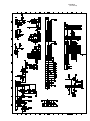
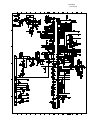
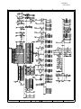
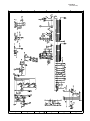
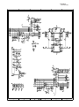
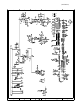
Appendix 3.
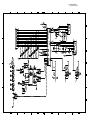
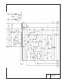
Circuit Diagrams
This manual describes the models and their versions to be destined for major countries. The specifications
and functions are subject to change depending upon each destination.
CHAPTER 1
GENERAL DESCRIPTION
CHAPTER 1 GENERAL DESCRIPTION
CONTENTS
1.1
1.2
EQUIPMENT OUTLINE ...................................................................................................1-1
1.1.1
External Appearance and Weight ........................................................................1-1
1.1.2
Components .........................................................................................................1-1
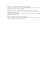
SPECIFICATIONS............................................................................................................1-2
1.1 EQUIPMENT OUTLINE
1.1.1 External Appearance and Weight
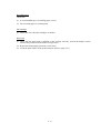
The figure below shows the equipment appearance and approximate dimensions.
(H)
217 mm
8.5"
(W)
426 mm
16.8"
(including handset)
Weight:
(D)
342 mm
13.5"
Machine proper
In package
Approx. 6.5 kg (14.3 lbs.)
Approx. 10.5 kg (23.2 lbs.)
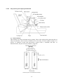
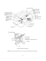
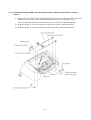
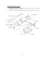
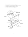
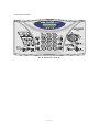
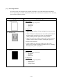
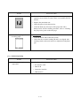
1.1.2 Components
The equipment consists of the following major components:
Control panel ASSY
Top cover
Upper cover
Handset and
curled cord*
Jam clear cover
Auto sheet feeder (ASF)
Purge unit
Main chassis
Lower cover
Enclosure cover
Bottom plate
Power supply PCB
Ink absorber box
Bottom shield
Main PCB
NCU PCB
1 -1
* Provided in the MFC3200C/FAX1800C.
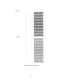
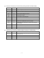
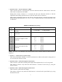
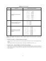
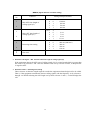
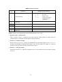
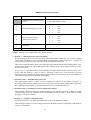
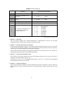
1.2 SPECIFICATIONS
Model Name
MFC 3100C
GENERAL
Print Engine
Modem Speed (bps)
Transmission Speed (sec.)
ITU-T Group
Coding Method
Document/Print Paper Width
Document/Print Paper Length
Print Paper Margin (upper, lower, left, right)
ADF (pages)
LCD Columns
LCD Line
LCD Backlight
Backup Clock
Memory Backup
Memory Capacity (physical)
Optional Memory
Dimensions w/o Carton (WxDxH)
Dimensions w Carton (WxDxH)
Weight w/o Carton
Weight w Carton
Color
Operating Environment Temperature
Humidity
Power Source
Power Consumption (Standby/Peak)
On/Off Switch
Ink Jet (BH 2-head)
14,400 (Fax)
6 (Brother#1,MMR)
G3
MH/MR/MMR/JPEG
3.5"-8.5"/3.5"-8.5"
5.0"-14"/5.0"-14"
0.12, 0.43, 0.12, 0.12 inch (3,11, 3, 3 mm)
Up to 20
16 characters
Single line
No
Yes
N/A
4MB
No
16.8"x13.5"x8.5" (426x342x217 mm)
20.4"x18.0"x14.8" (517x458x375 mm)
6.5kg/14.3lbs
10.5 kg/23.2lbs
Gray 1495
5 - 35 degrees Centigrade
60% +-25%
120VAC 50/60Hz
Under 7W/35W
No
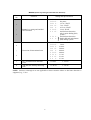
TELEPHONE
No
No
Max. 40
No
Yes
No
No
Yes
No
No
No
No
Yes (2 steps + OFF)
No
Handset
One-Touch Dial
Speed Dial
Speaker Phone
Chain Dialing
Caller ID
Call Waiting Caller ID
Distinctive Ringing
Hold/Mute Key
Hook Key
Power Failure Dialing
Speaker Volume
Ring Volume
Handset Volume
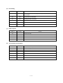
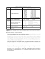
FAX
Scan Speed (A4:Standard)
Memory Transmission (Brother#1 Chart)
Memory Transmission (ITU-T Chart)
Out-of-Paper Reception (Brother #1 Chart)
Out-of-Paper Reception (ITU-T Chart)
Color FAX (Document Send/Receive)
Color FAX (Memory Send/Receive)
Approx. 5 sec./page (A4:standard)
Yes (100:MMR)
Yes (85:MMR)
Yes (100:MMR)
Yes (85:MMR)
Yes/Yes
No/Yes
INTERFACE
Yes
Yes
Yes
No
External TAD Interface
Host Interface (IEEE1284)
Host Interface (USB)
LAN Interface
1 -2
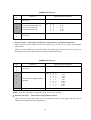
Model Name
MFC 3100C
PRINTER
Color/Mono
Piezo Ink Jet (2-head BH: 75 nozzles/color)
1200x1200 /2400x1200 (Mono/Color)
Color/Mono
Engine Type
Resolution (dpi)
10/8 (Mono/Color: 600*150)
4/3.5 (Mono/Color: 600*300)
2/1.5 (Mono/Color: 600*600)
0.2/0.2 (Mono/Color: 1200*1200/2400*1200)
Speed (ppm)
100
50
Windows GDI
No
Yes
Yes
LTR, LGL, A4, B5, A5, EXE,
Post Card, Index Card
N/A
OHP, Envelopes
Paper Capacity (sheets)
Output Paper Capacity (sheets)
Standard Print Language
Emulation
Resident Fonts
Fonts Disk Based
Paper Handling Size
Manual Feed Slot
Other Paper Type
Sheet Weight
(Paper Cassette)
(Manual Slot)
Printer Driver
64-120 g/m2 (17 - 32 lb)
N/A
Win95/98/98SE/Me/2000Professional/NT4.0/
MacOS 8.5-9.1
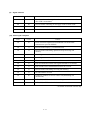
COPY
Color/Mono
7/4 (Mono/Color)
Yes (B&W only) or Via PC
N/A or Via PC
Max. 1200x1200 (color)
Color/Mono
Speed (cpm)
Multi Copy(Stack)
Multi Copy (Sort)
Resolution (dpi)
SCANNER
Color/Mono
Resolution (dpi) (Physical)
Resolution (dpi) (Logical)
Speed (ppm)
Gray Scale
TWAIN Compliant & Operating System
PCI Scanner (Parallel/Serial)
Color/Mono
CIS: 300x600 (Opt.)
2400 (Int.)
Max. 5sec
256
Win95/98/98SE/2000Professional/NT4.0/Me
MacOS 8.6-9.1
Parallel/USB
ACCESSORY
4 colors (each separate tank)
Black: 950, Color: 450
Cartridge
Life / Yield (Normal, 5% Coverage)
1 -3
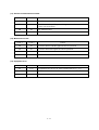
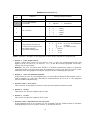
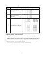
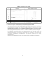
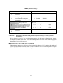
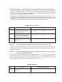
Model Name
MFC-580
GENERAL
Ink Jet (BH 2-head)
14,400 (Fax)
Transmission Speed (sec.)
6(Brother#1,MMR)
ITU-T Group
G3
Coding Method
MH/MR/MMR/JPEG
Document/Print Paper Width
90-216/90-216mm
Document/Print Paper Length
127-356/127-356mm
Print Paper Margin (upper, lower, left, right) 0.12, 0.43, 0.12, 0.12 inch (3,11, 3, 3 mm)
ADF (pages)
Up to 20
LCD Colums
16 characters
LCD Line
1 Line
LCD Backlight
N/A
Backup Clock
Yes (1 hour)
Memory Backup
N/A
Memory Capacity (Physical)
2MB as spec.(Actually 8MB)
Optional Memory
No
Dimensions w/o Carton (WxDxH)
16.8"x13.5"x8.5" (426x342x217 mm)
Dimensions w Carton (WxDxH)
20.4"x18.0"x14.8" (517x458x375 mm)
Weight w/o Carton
6.5kg/14.3lbs
Weight w Carton
10.5 kg/23.2lbs
Color
Gray 1495
5 - 35 degrees Centigrade
Operating Environment Temperature
Humidity
60% +-25%
Power Source
240VAC 50/60Hz
Power Consumption (Standby/Peak)
Under 6W/35W
On/Off Switch
No
Print Engine
Modem Speed (bps)
TELEPHONE
N/A
N/A
40
No
Yes
No
No
Yes (only for UK, Denmark)
No
Tel (for F/T switch)
No
No
Yes (2 steps + OFF)
No
Handset
One-Touch Dial
Speed Dial
Speaker Phone
Chain Dialing
Caller ID
Call Waiting Caller ID
Distinctive Ringing
Hold/Mute Key
Hook Key (Tel key)
Power Failure Dialing
Speaker Volume
Ring Volume
HandSet Volume
FAX
Scan Speed (A4:Standard)
Memory Transmission (Brother#1 Chart)
Memory Transmission (ITU-T Chart)
Approx. 5 sec./page (A4:standard)
Yes (100:MMR)
Yes (85:MMR)
Out-of-Paper Reception (Brother #1 Chart)
Yes (100:MMR)
Out-of-Paper Reception (ITU-T Chart)
Yes (85:MMR)
Yes/Yes
No/Yes
Color FAX (Document Send/Receive)
Color FAX (Memory Send/Receive)
INTERFACE
Yes
Yes
Yes
No
External TAD Interface
Host Interface (IEEE1284)
Host Interface (USB)
LAN Interface
1 -4
Model Name
MFC-580
PRINTER
Color/Mono
Engine Type
Resolution (dpi)
Speed(ppm)
Paper Capacity (sheets)
Output Paper Capacity (sheets)
Standard Print Language
Emulation
Resident Fonts
Fonts Disk Based
Paper Handling Size
Manual Feed Slot
Other Paper Type
Sheet Weight
(Paper Cassette)
(Manual Slot)
Printer Driver
Color/Mono
Piezo Ink Jet (2-head BH: 75 nozzles/color)
1200x1200/2400x1200 (B&W/Color)
10/8 (Mono/Color: 600*150)
4/3.5 (Mono/Color: 600*300)
2/1.5 (Mono/Color: 600*600)
0.2/0.2 (Mono/Color:
1200*1200/2400*1200)
100
50
Windows GDI
N/A
Yes
Yes
LTR, LGL, A4, B5, A5, EXE,
Photo Card, Index Card
N/A
OHP, Envelopes
64-105 g/m2 (17 - 28 lb)
N/A
Win95/98/98SE/Me/2000Professional/NT4.0/
MacOS 8.5-9.1
COPY
Color/Mono
7/4 (Mono/Color)
Yes (B&W only) or Via PC
N/A or Via PC
Max. 1200x1200
Color/Mono
Speed (ppm)
Multi Copy (Stack)
Multi Copy (Sort)
Resolution (dpi)
SCANNER
Color/Mono
Resolution (dpi) (Physical)
Resolution (dpi) (Logical)
Speed (ppm)
Gray Scale
TWAIN Compliant & Operating System
PCI Scanner (Parallel/Serial)
Color/Mono
CIS: 300x600 (Opt.)
2400 (Int.)
Max. 5sec
256
Win95/98/98SE/2000Professional/NT4.0/Me
MacOS 8.6-9.1
Parallel/ USB
ACCESSORY
4 colors (each separate tank)
Black: 950, Color: 450
Cartridge
Life / Yield (Draft, 5% Coverage)
1 -5
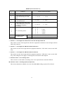
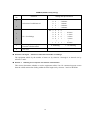
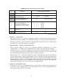
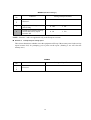
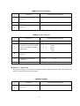
Model Name
Fax 3200C
Fax 1800C
Ink Jet (BH 2-head)
33,600 (Fax)
4 (Brother#1,MMR)
G3
MH/MR/MMR/JPEG
3.5"-8.5"/3.5"-8.5"
5.0"-14"/5.0"-14"
0.12, 0.43, 0.12, 0.12 inch (3,11, 3, 3 mm)
up to 20
16 Characters
1 Line
No
Yes
N/A
8MB (RAM)
No
19.1"x13.5"x8.5" (486x342x217 mm)
22.6"x18.0"x14.8" (573x458x375 mm)
6.5 kg (14.3 lbs.)
9.2 kg (20.3 lbs.)
Gray 1495/Purple 6255
10 - 35 degrees Centigrade
60% +-25%
120 VAC 50/60Hz
under 7W/35W
No
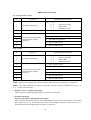
Yes
8 (4x2)
100
No
Yes
Yes
Yes
Yes
No
Yes
Yes (2 steps + OFF)
Yes
Yes
12 (6x2)
100
No
Yes
Yes
Yes
Yes
No
Yes
Yes (2 steps + OFF)
Yes
Approx. 8 sec./page (A4:standard)
Yes (480:MMR)
Yes (400:MMR)
Yes (480:MMR)
Yes (400:MMR)
Yes/Yes
No/Yes
Approx. 8 sec./page (A4:standard)
Yes (480:MMR)
Yes (400:MMR)
Yes (480:MMR)
Yes (400:MMR)
Yes/Yes
No/Yes
Yes
No
Yes
No
Yes
No
Yes
No
GENERAL
Print Engine
Modem Speed (bps)
Transmission Speed (sec.)
ITU-T Group
Coding Method
Document/Print Paper Width
Document/Print Paper Length
Print Paper Margin (upper, lower, left, right)
ADF (pages)
LCD Columns
LCD Line
LCD Back Light
Backup Clock
Memory Backup
Memory Capacity (Physical)
Optional Memory
Dimensions w/o Carton (WxDxH)
Dimensions w/ Carton (WxDxH)
Weight w/o Carton
Weight w/ Carton
Color
Operating Environment Temperature
Humidity
Power Source
Power Consumption (Standby/Peak)
On/Off Switch
TELEPHONE
Handset
One-Touch Dial
Speed Dial
Speaker Phone
Caller ID
Distinctive Ringing
Hold/Mute Key
Hook Key (Tel key)
Power Failure Dialing
Speaker Volume
Ring Volume
Handset Volume
FAX
Scan Speed (A4:Standard)
Memory Transmission (Brother#1 Chart)
Memory Transmission (ITU-T Chart)
Out-of-Paper Reception (Brother #1 Chart)
Out-of-Paper Reception (ITU-T Chart)
Color FAX (Document Send/Receive)
Color FAX (Memory Send/Receive)
INTERFACE
External TAD Interface
Host Interface (IEEE1284)
Host Interface (USB)
LAN Interface
1 -6
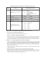
Model Name
Fax 3200C
Fax 1800C
Color/Mono
Piezo Ink Jet (2-head BH: 75 nozzles/color)
1200x1200 /2400x1200 (Mono/Color)
10/8 (Mono/Color: 600*150)
4/3.5 (Mono/Color: 600*300)
2/1.5 (Mono/Color: 600*600)
0.2/0.2 (Mono/Color: 1200*1200/2400*1200)
100
50
Windows GDI
No
Yes
Yes
LTR, LGL, A4, B5, A5, EXE,
Post Card, Index Card
N/A
OHP, Envelopes
64-120 g/m2 (17 - 32 lb)
N/A
Win/98/98SE/Me/2000Professinal/
MacOS 8.5.1/8.6/9.0/9.0.4/9.1/9.2.1/10.1
Color/Mono
Piezo Ink Jet (2-head BH: 75 nozzles/color)
1200x1200/2400x1200 (B&W/Color)
10/8 (Mono/Color: 600*150)
4/3.5 (Mono/Color: 600*300)
2/1.5 (Mono/Color: 600*600)
0.2/0.2 (Mono/Color: 1200*1200/2400*1200)
100
50
Windows GDI
N/A
Yes
N/A
Color/Mono
7/4 (Mono/Color)
Yes (B&W/Color)
N/A (B&W/Color)
Max. 1200x1200
Color/Mono
7/4 (Mono/Color)
Yes (B&W/Color)
N/A (B&W/Color)
Max. 1200x1200
Color/Mono
CIS: 300x600 (Opt.)
2400 (Int.)
Max. 5 sec
256
Win95/98/98SE/2000Professinal/NT4.0/Me
MacOS 8.6-9.1
Parallel/USB
Color/Mono
CIS: 300x600 (Opt.)
N/A
N/A
N/A
N/A
4 colors (each separate tank)
BK: 950, CL: 450
4 colors (each separate tank)
BK: 950, CL: 450
PRINTER
Color/Mono
Engine Type
Resolution (dpi)
Speed (ppm)
Paper Capacity (sheets)
Output Paper Capacity (sheets)
Standard Print Language
Emulation
Resident Fonts
Fonts Disk Based
Paper Handling Size
Manual Feed Slot
Other Paper Type
Sheet Weight
(Paper Cassette)
(Manual Slot)
Printer Driver
LTR, LGL, A4, B5, A5, EXE, Post Card
N/A
OHP, Envelopes
64-150 g/m2 (17 - 32 lb)
N/A
Win/98/98SE/Me/2000Professinal/
MacOS 8.5/8.5.1/8.6/9.0/9.0.4/9.1
COPY
Color/Mono
Speed (ppm)
Multi Copy (Stack)
Multi Copy (Sort)
Resolution (dpi)
SCANNER
Color/Mono
Resolution (dpi) (Physical)
Resolution (dpi) (Logical)
Speed (ppm)
Gray Scale
TWAIN Compliant & Operating System
PCI Scanner (Parallel/Serial)
N/A
ACCESSORY
Cartridge
Life / Yield (Draft, 5% Coverage)
1 -7
CHAPTER 2
INSTALLATION
CHAPTER 2 INSTALLATION
CONTENTS
2.1
INSTALLING THE UPDATE DATA TO THE FACSIMILE MACHINE.............................2-1
2.2
SETTING ID CODES TO FACSIMILE MACHINES .........................................................2-5
2.3
UPDATING HEAD PROPERTY INFO STORED IN THE FACSIMILE MACHINE ..........2-8
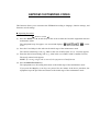
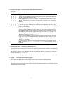
2.1 INSTALLING THE UPDATE DATA TO THE
FACSIMILE MACHINE
If you want to update the current program stored in the flash ROM of the main PCB to the newer
version or after you replace the main PCB, install the update program onto the flash ROM.
The program installation requires a PC/AT-compatible computer running MS-DOS,
Windows 95, or Windows 98. For the MFC3200C/FAX1800C, it requires Windows 98,
Windows Me, or Windows2000.
MFC3100C/MFC580
Setting up the facsimile machine and your PC
(1) Make sure that your PC is turned off.
(2) Make sure that the power cord of the facsimile machine is unplugged from a wall socket.
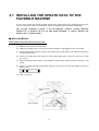
(3) Connect the parallel interface cable to the parallel port on the back of the machine and secure
it with the lock wires.
(4) Connect the other end of the interface cable to the printer port of your PC and secure it with
two screws.
(5) While holding down the 5 key on the machine's control panel, plug the power cord into a wall
socket.
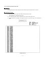
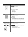
(6) Check to see that the following pattern displays on the LCD. If it does not display, go back to
step (2) above.
(7) Turn on your PC.
Parallel interface
cable
Lock wires
Host computer
2 -1
Installing the update data onto the flash ROM of the facsimile machine
NOTE: The following is an installation procedure example on a PC that is running Windows 98.
(1) Copy the update data and transfer utility onto the desired directory of the hard disk.
e.g., C:\UPDATE
(2) Click the Start button, point to Programs, and then click MS-DOS Prompt to open an MS-DOS
window.
(3) Type the drive letter where the update data and transfer utility are located. In the above
example, type C:\ from the command line and press the ENTER key.
Then type CD UPDATE and press the ENTER key.
(4) Check that your PC is connected with the facsimile machine correctly.
(5) To start the transfer utility transmitting the update data to the flash ROM of the facsimile
machine, type the following:
ICEN filename /b
Where filename is an update data file, e.g., 3100x.upd and 580xxxx.upd.
Then press the ENTER key.
During downloading, the machine beeps intermittently.
Upon completion of the downloading, the machine beeps continuously.
NOTE: If the facsimile machine cannot return to the standby state after completion of downloading,
turn the power off and on.
2 -2
MFC3200C/FAX1800C
CAUTION: During installation, do not turn the power off, interrupt downloading, or download invalid data.
If you do so, downloading will fail so that you need to replace the main PCB of the facsimile machine with a
new one and download update data again. The failure PCB is no longer usable.
Installing the printer driver to your PC
If the MFC3200C/FAX1800C is first connected to your PC, no printer driver is installed to your
PC. According to the following steps, install the printer driver.
(1) Turn on your PC.
(2) While holding down the Menu key, plug the power cord of the facsimile machine into a wall
socket.
NOTE: Use a facsimile machine whose operation is assured.
NOTE: This step makes the facsimile machine enter the special maintenance mode. In this
mode an ID code common to all facsimile machines of the same model will be assigned in
installing the printer driver. Once installed, the printer driver can be therefore applied to any
facsimile machine of the same model.
The following pattern will display on the LCD:
(3) Connect the USB cable to the USB port on the back of the machine.
(4) Connect the other end of the cable to the USB port of your PC.
(5) Your PC will detect newly connected hardware and start the Found New Hardware wizard.
Following the instructions displayed on the PC's screen, install the printer driver. (If the
wizard will not start, try to install the driver from the Add New Printer wizard by doubleclicking the Add New Printer icon in the printer folder of Windows' control panel.)
(6) After completion of installation, unplug the USB cable from your PC and restart it.
(7) Press the 9 key on the machine's control panel twice and wait for the LCD to display the
calendar clock. Then unplug the power cord from the wall socket.
USB interface
cable
Host computer
2 -3
Setting up the facsimile machine and your PC
If you want to update the current program to the newer version:
(1) Make sure that your PC is turned on.
(2) Make sure that the power cord of the facsimile machine is unplugged from the wall socket.
(3) While holding down the Menu key, plug the power cord of the facsimile machine into a wall
socket.
(4) Connect the USB cable to the USB port of the facsimile machine.
(5) Connect the other end of the cable to the USB port of your PC.
(6) Press the 0, 3, and 2 keys on the machine's control panel.
After you replace the main PCB with a new one:
(1) Plug the power cord of the facsimile machine into a wall socket.
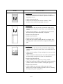
The following pattern will display on the LCD:
(2) Turn on your PC.
(3) Connect the USB cable to the USB port on the back of the machine.
(4) Connect the other end of the cable to the USB port of your PC.
Installing the update data onto the flash ROM of the facsimile machine
NOTE: The following is an installation procedure example on a PC that is running Windows 98.
(1) Get "Filedg32.exe" utility and save it onto the desk top of your PC.
(2) Double-click the “Filedg32” icon.
The Filedrgs window will appear.
(3) Drag and drop the firmware update file (ex. 1800usaC.dat) onto the printer icon (e.g., "Brother
FAX1800C") in the Filedrgs window.
During downloading, the facsimile machine beeps intermittently.
Upon completion of the downloading, the facsimile machine beeps continuously.
(4) If continuous beeping stops, immediately disconnect the USB interface cable from the
facsimile machine and your PC.
NOTE: If the USB interface cable remains connected even after continuous beeping stops,
then the facsimile machine will return to the standby mode and the Found New Hardware
wizard will start. The printer driver with the unique ID code (which is not common to
facsimile machines of the same model) will be installed to the connected PC unexpectedly.
2 -4
2.2 SETTING ID CODES TO FACSIMILE
MACHINES
Brother facsimile machines are assigned unique ID codes (character strings) at the factory. If you
replace the main PCB of the machine, the machine will lose its assigned ID code so that it will not
be identified by the connected PC*.
You need to assign a unique ID code (character string) to the machine according to the procedure
given here. For models covered by this manual, set serial numbers given to individual machines as
ID codes.
(*ID codes are essential when more than one machine is connected to a single PC via USB.)
MFC3100C/MFC580
Connecting the facsimile machine to your PC (See the illustration on page 2-1.)
(1) Make sure that your PC is turned off.
(2) Make sure that the power cord of the facsimile machine is unplugged from a wall socket.
(3) Connect the parallel interface cable to the parallel interface port on the back of the facsimile
machine and secure it with the lock wires.
(4) Connect the other end of the interface cable to the printer port of your PC.
(5) While holding down the Menu key, plug the machine's power cord into a wall socket.
(6) Turn on your PC.
Go to the Running the setup utility on the next page.
MFC3200C/FAX1800C
Installing the printer driver to your PC
If the MFC3200C/FAX1800C is first connected to your PC, no printer driver is installed to your
PC. According to the following steps, install the printer driver.
(1) Turn on your PC.
(2) While holding down the Menu key, plug the power cord of the facsimile machine into a wall
socket.
NOTE: Use a facsimile machine whose operation is assured.
NOTE: This step makes the facsimile machine enter the special maintenance mode. In this
mode an ID code common to all facsimile machines of the same model will be assigned in
installing the printer driver. Once installed, the printer driver can be therefore applied to any
facsimile machine of the same model.
The following pattern will display on the LCD:
2 -5
(3) Connect the USB cable to the USB port on the back of the machine.
(4) Connect the other end of the cable to the USB port of your PC.
(5) Your PC will detect newly connected hardware and start the Found New Hardware wizard.
Following the instructions displayed on the PC's screen, install the printer driver. (If the
wizard will not start, try to install the driver from the Add New Printer wizard by doubleclicking the Add New Printer icon in the printer folder of Windows' control panel.)
(6) After completion of installation, unplug the USB cable from your PC and restart it.
(7) Press the 9 key on the machine's control panel twice and wait for the LCD to display the
calendar clock. Then unplug the power cord from the wall socket.
Setting up the facsimile machine and your PC (See the illustration on page 2-3.)
(1) Make sure that your PC is turned on.
(2) Make sure that the power cord of the facsimile machine is unplugged from the wall socket.
(3) While holding down the Menu key, plug the power cord of the facsimile machine into a wall
socket.
(4) Connect the USB cable to the USB port of the facsimile machine.
(5) Connect the other end of the cable to the USB port of your PC.
Go to the Running the setup utility below.
MFC3100C/MFC580/MFC3200C/FAX1800C
Running the setup utility
(1) On your PC, run the ID/head property setup utility (BRUSBSN.EXE). The following window
will appear.
(2) On the Model menu, click BH.
MFC3100C/MFC580: Click the Port down arrow to select the LPT1.
MFC3200C/FAX1800C: Click the Port down arrow to select the USB port to which the
MFC3200C/FAX1800C is connected.
2 -6
(3) In the Serial No = BRO box, type the 9-digit serial number (e.g., L2J012345) printed on the
nameplate labeled to the back of the facsimile machine as an ID code. Then press the Enter
key.
The setup utility will transmit the entered data from your PC to the facsimile machine and
then it will terminate.
The facsimile machine will automatically return to the standby mode.
(4) To check whether the entered character string (ID code) is correct, make the machine enter the
maintenance mode (refer to CHAPTER 5, Section 5.1) and then press the 1 key twice
(Subsection 5.3.5).
The facsimile machine will print out a Configuration List. At the right top of the list, "SER.#:
BROXXXXXXXXX" is printed.
(5) Check that the character string entered in step (3) is printed in "XXXXXXXXX."
If it is OK, press the 9 key twice to exit from the maintenance mode.
If something other than that is printed in XXXXXXXXX, check the connection between the
PC and facsimile machine and go back to step (1).
2 -7
2.3 UPDATING HEAD PROPERTY INFO STORED
IN THE FACSIMILE MACHINE
To keep the print quality, the controller optimizes the head drive strength, ink jet-out timing, and
other drive conditions depending upon the electromechanical properties unique to individual print
heads and ambient temperature. The head property information is stored in the EEPROM of the
main PCB.
If you replace the print head unit and/or main PCB of the machine, then you need to update head
property information according to the procedure given here.
TIP: The updating procedure given here uses a PC. For the updating procedure in the maintenance
mode without using a PC, refer to CHAPTER 5, Subsection 5.3.14.
MFC3100C/MFC580
Connecting the facsimile machine to your PC (See the illustration on page 2-1.)
(1) Make sure that your PC is turned off.
(2) Make sure that the power cord of the facsimile machine is unplugged from a wall socket.
(3) Connect the parallel interface cable to the parallel interface port on the back of the facsimile
machine and secure it with the lock wires.
(4) Connect the other end of the interface cable to the printer port of your PC.
(5) While holding down the Menu key, plug the machine's power cord into a wall socket.
(6) Turn on your PC.
Go to the Running the setup utility on the next page.
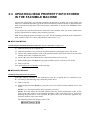
MFC3200C/FAX1800C
Installing the printer driver to your PC
If the MFC3200C/FAX1800C is first connected to your PC, no printer driver is installed to your
PC. According to the following steps, install the printer driver.
(1) Turn on your PC.
(2) While holding down the Menu key, plug the power cord of the facsimile machine into a wall
socket.
NOTE: Use a facsimile machine whose operation is assured.
NOTE: This step makes the facsimile machine enter the special maintenance mode. In this
mode an ID code common to all facsimile machines of the same model will be assigned in
installing the printer driver. Once installed, the printer driver can be therefore applied to any
facsimile machine of the same model.
The following pattern will display on the LCD:
2 -8
(3) Connect the USB cable to the USB port on the back of the machine.
(4) Connect the other end of the cable to the USB port of your PC.
(5) Your PC will detect newly connected hardware and start the Found New Hardware wizard.
Following the instructions displayed on the PC's screen, install the printer driver. (If the
wizard will not start, try to install the driver from the Add New Printer wizard by doubleclicking the Add New Printer icon in the printer folder of the Windows' control panel.)
(6) After completion of installation, unplug the USB cable from your PC and restart it.
(7) Press the 9 key on the machine's control panel twice and wait for the LCD to display the
calendar clock. Then unplug the power cord from the wall socket.
Setting up the facsimile machine and your PC (See the illustration on page 2-3.)
(1) Make sure that your PC is turned on.
(2) Make sure that the power cord of the facsimile machine is unplugged from the wall socket.
(3) While holding down the Menu key, plug the power cord of the facsimile machine into a wall
socket.
(4) Connect the USB cable to the USB port of the facsimile machine.
(5) Connect the other end of the cable to the USB port of your PC.
Go to the Running the setup utility below.
MFC3100C/MFC580/MFC3200C/FAX1800C
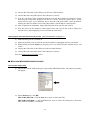
Running the setup utility
(1) On your PC, run the ID/head property setup utility (BRUSBSN.EXE). The following window
will appear.
(2) On the Model menu, click BH.
MFC3100C/MFC580: Click the Port down arrow to select the LPT1.
MFC3200C/FAX1800C: Click the Port down arrow to select the USB port to which the
MFC3200C/FAX1800C is connected.
2 -9
(3) In the Head Info. box, type the whole 13-digit property code (enclosed with asterisks, e.g.,
*66667F657031H*) which is printed on the bar code label attached to the print head unit.
Then press the Enter key.
The setup utility will transmit the entered data from your PC to the facsimile machine and
then it will terminate.
The facsimile machine will automatically return to the standby mode.
(4) To check whether the entered head property is correct, make the machine enter the
maintenance mode (refer to CHAPTER 5, Section 5.1) and then press the 7 key twice.
The facsimile machine will print out the Equipment's Log. On the line about 1/3 of full length
of the log sheet below from the top, the 12-digit code is printed.
NOTE: The MFC3100C may fail to print it out correctly if the four starting numerals of the
entered property code are other than 6666, 7777, and 8888. To print it correctly, update the
current program stored in the EEPROM.
(5) Check that the character string entered in step (3) is printed in "XXXXXXXXXXXX."
If it is OK, press the 9 key twice to exit from the maintenance mode.
If something other than that is printed in XXXXXXXXXXXX, check the connection between
the PC and facsimile machine and go back to step (1).
2 -1 0
CHAPTER 3
THEORY OF OPERATION
CHAPTER 3 THEORY OF OPERATION
CONTENTS
3.1
OVERVIEW ......................................................................................................................3-1
3.2
MECHANISMS .................................................................................................................3-2
3.2.1
3.2.1.1
Document feeding and ejecting mechanism ................................................3-3
3.2.1.2
Scanner........................................................................................................3-3
3.2.2
Ink Jet Printing Mechanism ..................................................................................3-4
3.2.2.1
Paper pulling-in, registration, feeding, and ejecting mechanisms................3-4
3.2.2.2
Ink jet printing and capping mechanisms.....................................................3-6
3.2.2.3
Purging mechanism .....................................................................................3-9
3.2.2.4
Carriage drive mechanism .........................................................................3-12
3.2.3
3.3
Scanner Mechanism ............................................................................................3-3
Sensors and Actuators .......................................................................................3-13
CONTROL ELECTRONICS...........................................................................................3-16
3.3.1
Configuration ......................................................................................................3-16
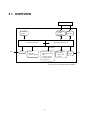
3.1 OVERVIEW
Host
Centronics
parallel
interface*
Control
panel
Fax Control Section
USB
interface
Printer Control Section
Print data
Line
NCU
Scanner
- CIS unit
- Scanner motor
Ink jet printer unit
- Ink jet print head
unit
- Carriage motor
- Carriage ASSY
- Purge unit
Paper feeding
mechanism
- Paper feed
motor
Power
supply
*Not provided in the MFC3200C/FAX1800C.
3 -1
AC
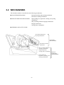
3.2 MECHANISMS
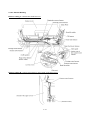
The facsimile machine is classified into the following mechanisms:
SCANNER MECHANISM
- Document feeding and ejecting mechanism
- Document scanning mechanism
INK JET PRINTING MECHANISM
- Paper pulling-in, registration, feeding, and ejecting
mechanisms
- Ink jet printing and head capping mechanisms
- Purging mechanism
- Carriage drive mechanism
SENSORS AND ACTUATORS
Document feeding and
ejecting mechanism
SCANNER
MECHANISM
Document scanning
mechanism
Ink jet printing and head
capping mechanisms
Purge mechanism
Carriage drive mechanism
Paper pulling-in,
registration, feeding, and
ejecting mechanisms
3 -2
INK JET
PRINTING
MECHANISM
3.2.1 Scanner Mechanism
3.2.1.1
Document feeding and ejecting mechanism
This mechanism consists of the document stacker, automatic document feeder (ADF), document
feed roller ASSY, document ejection roller ASSY, and document sensors. (For details about the
sensors, refer to Subsection 3.2.3.)
If you set documents on the document stacker with their faces down and start the scanning
operation, then the scanner motor rotates so that the ADF (which consists of the separation roller
and ADF parts) feeds those documents into the machine, starting from the bottom sheet (first page)
to the top (last page), page by page. Each document advances with the document feed roller ASSY
to the scanner, and then it is fed out of the machine with the document ejection roller ASSY.
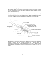
3.2.1.2
Scanner
The scanner uses a contact image sensor (CIS) unit which consists of an LED array illuminating
documents, a self-focus lens array collecting the reflected light, a CIS PCB carrying out
photoelectric conversion to output picture element data, and a cover glass on which a document
advances. When the document passes between the document pressure bar and the cover glass, it is
scanned.
3 -3
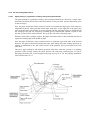
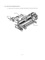
3.2.2 Ink Jet Printing Mechanism
3.2.2.1
Paper pulling-in, registration, feeding, and ejecting mechanisms
The paper pulling-in, registration, feeding, and ejecting mechanisms are driven by a single paper
feed motor located at the left side of the main chassis via the gear train. (See the illustration given
on the next page.)
First, the paper feed motor rotates clockwise (when viewed from the output gear). The rotation is
transmitted to the PF roller gear that rotates paper feed roller. At the right end of the paper feed
roller is the PF roller gear R which is always engaged with the ASF/purge idle gear. Engaged with
the ASF/purge idle gear, the ASF-purge switching gear 23 transmits the rotation via gear 25 and
the ASF gear train to the ASF roller unit. This way, the ASF roller will pull in paper.
When the ASF roller is pulling in paper, the paper feed roller rotates in the backward direction to
register the leading edge of the pulled-in paper.
Next, the paper feed motor rotates counterclockwise to rotate the paper feed roller in the forward
direction. The paper will advance through the paper path. During the paper feeding operation, no
rotation is transmitted to the ASF roller because of the planetary gear system built in the ASF
roller unit.
The above paper pulling-in and feeding operations take place when the carriage is in printing
operation. If the carriage reaches the purge position, the ASF-purge switching gear 23 will be
disengaged from the gear 25 and engaged with purge bevel gear A. For the purging mechanism,
refer to Subsection 3.2.2.3.
3 -4
Gear 31MF
Gear shaft 17
PF roller gear R
ASF roller unit
Gear 39
Paper feed
roller
Gear 25
ASF-purge
switching gear 23
ASF/purge idle gear
PF roller gear
Paper feed motor
3 -5
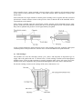
3.2.2.2
Ink jet printing and capping mechanisms
(1) Print head unit
This machine uses drop-on-demand ink jet printing. Each of the right and left print heads has an
ink-jet unit that has a pair of nozzle columns for two color inks. A nozzle column consists of 75
nozzles, 75 channels covered with piezoelectric ceramic (PZT), a manifold, and filter. As
illustrated below, the pair of nozzle columns is staggered.
Nozzle Layout (viewed from the bottom)
3 -6
If the controller issues a print command, a biased voltage will be applied to all electrodes formed
on the surface of the piezoelectric ceramic so that each actuator will be distorted as shown with
broken lines.
If the electrodes on a target channel are deenergized according to drive signals, then the associated
piezoelectric ceramic actuator returns to the previous form so that the ink in the manifold will be
vacuumed out to the channel.
If the voltage is applied again, the piezoelectric ceramic actuator will be distorted again to apply
pressure to the ink in the channel, causing the ink to jet out through the nozzle. The jetted-out ink
drop will be splashed and produce a dot on paper held by the platen.
As the carriage holding the print head unit travels at the printing speed, the controller sends print
command pulses to the piezoelectric actuator driver circuit embedded in the print head unit.
(2) Ink cartridges
The machine uses four ink cartridges (black, cyan, yellow, and magenta) of disposable type to
supply ink to the print head unit. As shown below, an ink cartridge contains an ink-impregnated
urethane foam. If ink-jet print operation or purging operation takes place, ink comes out of the
urethane foam and is supplied to the print head unit through the ink room, filters, and manifold.
For the ink cartridge sensors on the carriage PCB, refer to Subsection 3.2.3.
3 -7
(3) Head caps
Shown below is a head cap mechanism that prevents the nozzles of the print heads from drying up
when they are not in use.
Upon completion of printing, the carriage travels to the right and moves the head cap holder
provided on the purge unit to the right together. In the head cap holder is a head cap unit which is
supported with a lift lever. The rightward movement of the head cap holder turns the lift lever and
pushes up the head cap unit to the position where the head caps come into tight contact with the
print heads. This way, the nozzles will be capped.
3 -8
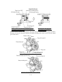
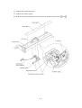
3.2.2.3
Purging mechanism
The purge mechanism is driven by the paper feed motor located at the left side of the main chassis.
As described in Subsection 3.2.2.1, the motor rotation is transmitted to the ASF/purge idle gear at
the right side of the main chassis. Engaged with the ASF/purge idle gear, the ASF-purge switching
gear 23 works as a clutch gear.
When the carriage travels from the left to right to reach the purge position, the tab provided on the
back of the carriage pushes the purge lever on the main chassis to the right (see the illustration
below). Accordingly, the ASF-purge switching gear 23 (which was shifted to the left by the purge
lever) will move to the right by the switching gear spring so as to become disengaged from the
gear 25 and engaged with the purge bevel gear A. (See the illustration given on the next page.)
This engagement will transmit the motor rotation to the purge bevel gear B on the purge unit. This
way, when the carriage is in the purge position, the motor rotation is transmitted to the purge unit.
On the contrary, if the carriage travels from the purge position to the left, the tab on the back of the
carriage releases the purge lever which will be pulled back to the left. The ASF-purge switching
gear 23 will be disengaged from the purge bevel gear A.
3 -9
During printing: The ASF-purge switching gear 23 is
not engaged with purge bevel gear A (but engaged with
gear 25 in the ASF gear train).
During purging: The ASF-purge
switching gear 23 is engaged with
purge bevel gear A.
When the motor rotation is transmitted to the purge unit, its counterclockwise rotation will drive
the purge cam and its clockwise rotation, the pump switching unit (when viewed from the output
gear of the motor).
When the paper feed motor rotates counterclockwise
When the paper feed motor rotates clockwise
3 -1 0
The purge cam is so designed that:
- the carriage lock pops out to lock the carriage before purging and pops in before cleaning with
the head wiper (see the illustration below),
- the pump works to draw out ink from each of the four head nozzles and drain it to the ink
absorber felts, and
- the head wiper comes out to clean the nozzle surface (see the illustration below).
The pump switching cam is so designed that:
- the pump switching unit switches application of the pump's negative pressure between the four
head nozzles in the order of black, cyan, yellow, and magenta nozzles. When the pump
switching cam is in the home position, normal atmospheric pressure will be restored.
The home position of the purge cam and pump switching cam are detected by their HP switches.
For those switches, refer to Subsection 3.2.3.
(1) Carriage lock
If the purge cam is driven, the carriage lock of the purge unit pops out and locks the carriage to
align ink-jet units with the mating head caps during purge operation. After purging but before
cleaning with the head wiper, it pops in to release the carriage. When the power is off, the carriage
lock keeps the print heads pressed against the head caps.
(2) Purging
If activated, the pump draws out ink to purge air bubbles or dust from the inside of the head
nozzles and channels. As the purge cam rotates by one turn, the piston of the pump reciprocates
two strokes. To complete purging of all four nozzles and channels, the purge cam rotates by two
turns ad the piston reciprocates four strokes.
(3) Draining
The pump drains drawn ink into the ink absorber felts.
(4) Cleaning with the head wiper
After purging operation, the head wiper comes out and the carriage moves from the right to left so
as to clean ink remaining on the heads' surface.
(5) Restoring the pump's pressure to normal atmospheric pressure
When the pump switching cam is in the home position, the controller stops to produce negative
pressure and restore the pump's pressure to normal atmospheric pressure.
3 -1 1
3.2.2.4
Carriage drive mechanism
The carriage motor controls horizontal motion. The motor rotation is transmitted via the motor
pulley to the timing belt.
The carriage, which is supported and guided by the carriage rail, is secured to the timing belt.
Clockwise and counterclockwise rotations of the carriage motor move the carriage to the right and
left, respectively.
On the back of the carriage is the carriage encoder which tells the control circuitry the current
carriage position counted based on the carriage motor position by using the encoder strip attached
to the main chassis.
3 -1 2
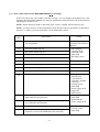
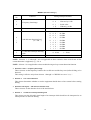
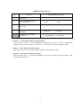
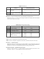
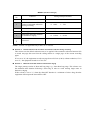
3.2.3 Sensors and Actuators
This machine has the following sensors and thermister.
Sensor name
Type
Located on
Document front sensor
Photosensor
Document rear sensor
Photosensor
Cover/panel open sensor
Mechanical switch
Registration sensor
Photosensor
Paper chute
Paper width sensor
Photosensor
Main PCB
Ink empty sensor
Photosensor
Sensor support
Ink cartridge sensors
Mechanical switches
Carriage encoder
Photosensor
Head thermister
Thermister
Purge cam HP switch
Mechanical switch
Pump switching cam HP switch
Mechanical switch
Hook switch*
Mechanical switch
Control panel PCB
Carriage PCB
Purge unit
Hook switch PCB*
*Provided in the MFC3200C/FAX1800C.
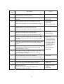
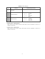
• Document front sensor which detects the presence of documents.
• Document rear sensor which detects the leading and trailing edges of pages to tell the control
circuitry when the leading edge of a new page has reached the starting position and when the
scan for that page is over.
• Cover/panel open sensor which detects whether the top cover and control panel are closed.
• Registration sensor which detects the leading and trailing edges of paper, which allows the
controller to determine the registration timing and check paper jam.
• Paper width sensor which detects whether the paper width is "A4-size or wider" or "narrower
than A4-size."
• Ink empty sensor which detects at the start of printing whether any of the four ink cartridges is
near empty. According to this sensor signal, the controller may display "NEAR EMPTY XXX"
message.
• Ink cartridge sensors, each of which detects whether an ink cartridge is loaded.
• Carriage encoder which detects the current carriage position and carriage travel speed. If the
carriage travels speed varies abnormally, the controller regards it as a paper jam.
• Head thermister which allows the controller to control the temperature of the print heads.
According to the change of the thermister's internal resistance monitored, the control circuitry
regulates the drive voltage applied to the piezoelectric ceramic actuators on each print head
since the viscosity of the ink varies depending upon the temperature.
• Purge cam HP switch which detects whether the purge cam is in the home position.
• Pump switching cam HP switch which detects whether the pump switching cam is in the home
position.
• Hook switch which detects whether the handset is on the hook.
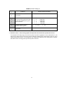
3 -1 3
These photosensors (except the ink empty sensor that is a reflection type) are a photointerrupter
consisting of a light-emitting diode and a light-sensitive transistor. Each of them has an actuator
separately arranged as shown on the next page.
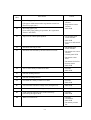
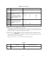
3 -1 4
Location of Sensors and Actuators
NOTE: The hook switch (not shown above) is provided in the MFC3200C/FAX1800C.
3 -1 5
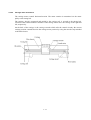
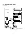
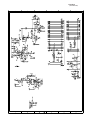
3.3 CONTROL ELECTRONICS
3.3.1 Configuration
The hardware configuration of the facsimile machine is shown below.
Control panel PCB
Document front sensor
8-pin
Document rear sensor
Paper width sensor
Cover/panel open sensor
Piezo ringer*3
INK JET
PRINTER
UNIT
Main PCB
Carriage PCB
Ink cartridge sensors
Print head
Print head
Carriage encoder
Head thermister
EEPROM
Engine *3
GA
3-pin
Ink empty sensor
Sensor
support
3-pin
Registration sensor
Paper
chute
DC motor
driver
2-pin
Stepping
motor driver
4-pin
Carriage motor
Paper feed motor
Purge cam HP switch
4-pin
Pump switching cam HP switch
SDRAM
(8MB/2MB)
Main
ASIC
9-pin
Stepping
motor driver
CIS unit
4-pin
7-pin
(10-pin)*1
ROM
(4MB)
Purge unit
SCANNER
Scanner motor
NCU PCB
Line
External telephone
MODEM
Hook switch*2
Speaker*2
11-pin
USB Parallel interface
(ECP)*3
*1
Power supply
PCB
AC line
PC
7-pin: American models
10-pin: Other models
*2 Provided in the MFC3200C/FAX1800C.
*3 Not provided in the MFC3200C/FAX1800C.
Configuration of Facsimile Machine
3 -1 6
CHAPTER 4
DISASSEMBLY/REASSEMBLY,
LUBRICATION, AND ADJUSTMENT
CHAPTER 4 DISASSEMBLY/REASSEMBLY, LUBRICATION,
ADJUSTMENT
CONTENTS
4.1
DISASSEMBLY/REASSEMBLY......................................................................................4-1
Safety Precautions ........................................................................................................4-1
Tightening Torque List......................................................................................................4-2
Preparation ...................................................................................................................4-3
How to Access the Object Component .........................................................................4-3
Disassembly Order Flow...............................................................................................4-4
4.1.1
Print Head Unit .....................................................................................................4-5
4.1.2
Jam Clear Cover and Auto Sheet Feeder (ASF)..................................................4-9
4.1.3
Bottom Plate, Ink Absorber Box, Main PCB, NCU PCB, and
Power Supply PCB .............................................................................................4-11
4.1.4
Enclosure Cover and Paper Width Sensor Actuator ..........................................4-16
4.1.5
Top Cover...........................................................................................................4-17
4.1.6
Control Panel ASSY ...........................................................................................4-18
4.1.7
Panel Rear Cover and Control Panel .................................................................4-19
4.1.8
CIS Unit ..............................................................................................................4-22
4.1.9
Upper Cover .......................................................................................................4-23
4.1.10 Document Feed Roller ASSY, Document Ejection Roller ASSY,
Pressure Roller, and Pinch Rollers ....................................................................4-25
4.1.11 Panel Lock Springs, Scanner Chassis, Separation Roller,
Scanner Drive Unit, and Scanner Motor.............................................................4-26
4.1.12 Purge Unit ..........................................................................................................4-29
4.1.13 Main Chassis......................................................................................................4-31
4.1.14 ASF Roller Unit and its Related Gears...............................................................4-32
4.1.15 Roller Pressure Holders .....................................................................................4-34
4.1.16 Paper Chute and Registration Sensor................................................................4-35
4.1.17 Paper Ejection Roller Gear, Ink Empty Sensor PCB, Platen,
Star Wheel Support, and Paper Ejection Roller .................................................4-37
4.1.18 Paper Feed Motor and Paper Feed Roller .........................................................4-40
4.1.19 Encoder Strip and Carriage Motor......................................................................4-41
4.1.20 Carriage Rail, Carriage ASSY, and Purge-Related Parts ..................................4-43
4.1.21 Flushing Box.......................................................................................................4-48
4.1.22 Harness Routing.................................................................................................4-49
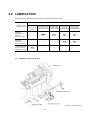
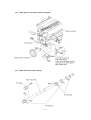
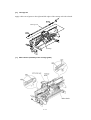
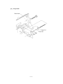
4.2
LUBRICATION ...............................................................................................................4-51
4.3
ADJUSTMENT ...............................................................................................................4-56
4.1 DISASSEMBLY/REASSEMBLY
Safety Precautions
To prevent the creation of secondary problems by mishandling, observe the following precautions
during maintenance work.
(1) Unplug the power cord from the power outlet before replacing parts or units. When having
access to the power supply, be sure to unplug the power cord from the power outlet.
(2) Be careful not to lose screws, washers, or other parts removed for parts replacement.
(3) When using soldering irons and other heat-generating tools, take care not to damage the resin
parts such as wires, PCBs, and covers.
(4) Before handling the PCBs, touch a metal portion of the machine to discharge static electricity;
otherwise, the electronic parts may be damaged due to the electricity charged in your body.
(5) When transporting PCBs, be sure to wrap them in conductive sheets such as aluminum foil.
(6) Be sure to reinsert self-tapping screws correctly, if removed.
(7) Tighten screws to the torque values listed on the next page.
(8) When connecting or disconnecting cable connectors, hold the connector bodies not the cables.
If the connector has a lock, always slide the connector lock to unlock it.
(9) Before reassembly, apply the specified lubricant to the specified points. (Refer to Subsection
4.2 in this chapter.)
(10) After repairs, check not only the repaired portion but also that the connectors and other related
portions function properly before operation checks.
(11) Once the print head unit prints, it will start head locking operation after five seconds from the
end of printing. The head locking operation will take 5 to 10 seconds. NEVER unplug the
power cord before the machine completes the head locking operation; doing so will make the
print head unit unusable and require replacement with a new print head unit.
When you receive the machine from the user or when you pack it for sending it back to the
user, check the head locking state.
4 -1
Tightening Torque List
Location
Screw type
Q'ty
Tightening torque
N•m (kgf•cm)
ASF
Taptite, bind B M4x12
4
0.88 ±0.10
(9 ±1)
Bottom plate
Grounding terminal
Taptite, cup B M3x12
Screw, pan (washer) M4x8
9
1
0.78 ±0.10
0.59 ±0.10
(8 ±1)
(6 ±1)
Bottom shield plate
Taptite, cup B M3x12
Taptite, cup S M3x5
2
2
0.78 ±0.10
0.49 ±0.10
(8 ±1)
(5 ±1)
Parallel & USB I/F connectors
Screw, pan M3x6
3
0.39 ±0.10
(4 ±1)
FG plate R (Lower cover)
(Main chassis)
Taptite, cup B M3x12
Taptite, cup S M3x5
1
1
0.78 ±0.10
0.78 ±0.10
(8 ±1)
(8 ±1)
ADF parts
Panel rear cover
Taptite, cup B M3x6
Taptite, cup B M3x8
1
2
0.49 ±0.10
0.49 ±0.10
(5 ±1)
(5 ±1)
CIS side spring
Taptite, cup B M3x10
1
0.78 ±0.10
(8 ±1)
Upper cover
Panel lock spring R
Panel lock spring L
Taptite, bind B M4x12
Taptite, cup S M3x5
Taptite, cup B M3x10
2
1
1
0.88 ±0.10
0.98 ±0.10
0.78 ±0.10
(9 ±1)
(10 ±1)
(8 ±1)
Scanner chassis
Scanner motor
Taptite, cup B M3x10
Screw, pan (s/p washer) M3x6DA
4
1
0.78 ±0.10
0.49 ±0.10
(8 ±1)
(5 ±1)
Purge unit
Taptite, cup B M3x8
2
0.59 ±0.10
(6 ±1)
FG plate L
Taptite, cup S M3x5
1
0.78 ±0.10
(8 ±1)
ASF roller unit
ASF gear holders
Taptite, cup S M3x6
Taptite, cup B M3x10
3
1
0.98 ±0.10
0.49 ±0.10
(10 ±1)
(5 ±1)
Paper chute
Taptite, cup S M3x6
1
0.98 ±0.10
(10 ±1)
Sensor support
Ink empty sensor PCB
Taptite, cup S M3x6
Taptite, cup B M3x8
1
1
0.98 ±0.10
0.59 ±0.10
(10 ±1)
(6 ±1)
Platen
Platen plate R
Platen plate L
Shoulder screw
Screw, bind B tite, M3x10
Taptite, bind B M2.6x10
Taptite, bind B M2.6x10
1
1
1
1
0.59 ±0.10
0.59 ±0.10
0.39 ±0.10
0.39 ±0.10
(6 ±1)
(6 ±1)
(4 ±1)
(4 ±1)
Paper feed motor
Screw, pan (s/p washer) M3x6
2
0.78 ±0.10
(8 ±1)
Idle pulley holder
Screw, pan (s/p washer) M3x8
Shoulder screw
Taptite, cup S M3x6
Screw, pan (s/p washer) M3x6
Screw, pan (s/p washer) M3x6DB
1
1
1
2
2
0.78 ±0.10
0.78 ±0.10
0.98 ±0.10
0.78 ±0.10
0.78 ±0.10
(8 ±1)
(8 ±1)
(10 ±1)
(8 ±1)
(8 ±1)
Carriage motor
Eccentric bushings R, L
4 -2
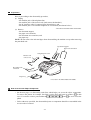
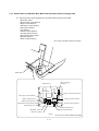
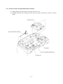
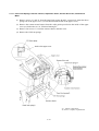
Preparation
Prior to proceeding to the disassembly procedure,
(1) Unplug
- the modular jack of the telephone line,
- the modular jack of the curled cord* (and remove the handset*),
- the PC interface cable if connected (Not shown below), and
- the modular jack of an external telephone set if connected (Not shown below).
*Provided in the MFC3200C/FAX1800C.
(2) Remove
- the document support,
- the paper wire extension,
- the document wire extension, and
- the paper tray.
NOTE: Do not remove the ink cartridges when disassembling the machine except when removing
the print head unit.
Document support
Paper wire extension
Telephone line cord
Handset and
curled cord*
Document wire
extension
Paper tray
* Provided in the MFC3200C/FAX1800C.
How to Access the Object Component
• On the next page is a disassembly order flow which helps you access the object components.
To remove the platen, for example, first find it on the flow and learn its number (
in this
case). You need to remove parts numbered
,
,
,
,
, and
so as to access the
platen.
• Unless otherwise specified, the disassembled parts or components should be reassembled in the
reverse order of removal.
4 -3
Disassembly Order Flow
4 -4
4.1.1 Print Head Unit
During disassembly jobs (except when removing the purge unit, carriage rail, or carriage
ASSY), the print head unit and all the four ink cartridges should be kept in place.
NOTE: To replace the print head unit with a new one, you need to move the carriage to the ink
replacement position by placing the machine in the ink replacement mode. Do not move the
carriage by hand when the power is off.
NOTE: If you replace the print head unit with a new one, replace also the ink absorber box and
ink cartridges with new ones.
(1) Plug the power cord into a wall socket.
(2) Press the Ink key to place the machine in the ink replacement mode.
(3) Press the 2 key to choose "2. REPLACE INK."
(4) Press the Menu/Set key.
The carriage automatically moves to the ink replacement position.
(5) Unplug the power cord from the wall socket.
(6) Open the control panel ASSY and top cover.
(7) Push the colored ink cartridge covers and remove all ink cartridges. (Or, remove the shipping
cover.)
4 -5
(8) Pull the head clamp springs in the direction of arrows
head unit.
(9) Lift the print head unit up and out of the carriage (arrow
shown below to release the print
).
Setting the head clamp spring
Top cover
Carriage
Head clamp spring
Head clamp spring
Correct
Carriage
Boss of the
print head unit
Print head unit
Locks provided
on the carriage
Boss of the carriage
Wrong
Control panel ASSY
Head clamp spring
Locks provided
on the carriage
Wrong
Boss of the print head unit
Boss of the carriage
NOTE: Do not touch the printing ends (nozzles) of the print head unit or the ink orifices of
the ink cartridges; doing so will not only stain your hands with ink but result in an ink jet-out
failure. Once you touch them, clean them with a dedicated cleaning stick and liquid.
NOTE: Be sure to put a head nozzle seal and filter seal on the print head unit as shown below.
Leaving the print head unit without those seals will dry up its printing ends and filters,
resulting in a damaged head.
NOTE: Do not touch the dimple contact section of the print head unit.
Head filter seal
Print head unit
Head nozzle seal
4 -6
NOTE: Once the ink cartridges are removed, their colored covers rise upright. If you turn the
machine upside down with those covers being upright, then they will break. To prevent it, set
and pushing them
them to the horizontal position by turning them in the direction of arrow
up in the direction of arrow .
(10) Turn the head adjuster lever located on the right side of the carriage to position 1.
(11) To install a new (or removed) print head unit, remove the head nozzle seal.
(12) Put the print head unit into the carriage with care for the dimple contact so that the electrical
contact on the head PCB comes into uniform contact with that on the carriage PCB as
illustrated below.
4 -7
(13) Press the front center of the carriage to the rear and move the print head unit to the right and
left several times. This is to assure the dimple contact between the head PCB and carriage
PCB.
(14) Remove the head filter seal.
Carriage
Print head unit
(15) While pressing the center of the print head unit as shown above, lock the print head unit with
the head clamp springs.
(16) Set new ink cartridges into the carriage.
(17) Press the bottom right front corner of the carriage to the rear.
(18) Close the top cover and control panel.
(19) Plug the power cord into a wall socket.
The carriage automatically moves to the right-hand home position.
(20) Follow the instructions shown on the LCD.
NOTE: The machine enters a "head cleaning" cycle that takes approx. 3 minutes for each ink
cartridge.
(21) Update the head property information stored in the EEPROM of the main PDB, referrring to
Section 2.3.
(22) Load paper into the ASF.
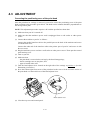
(23) Correct the positioning error of the print head unit, referring to Section 4.3 "ADJUSTMENT."
(24) Adjust the alignment of vertical print lines, referring to CHAPTER 5, Subsection 5.3.13.
4 -8
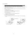
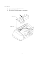
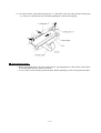
4.1.2 Jam Clear Cover and Auto Sheet Feeder (ASF)
(1) Remove the jam clear cover.
(2) Remove the four screws from the ASF to release it.
(3) Pull out the separation pad ASSY.
4 -9
(4) Disassemble the separation pad ASSY as shown below.
4 -1 0
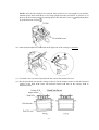
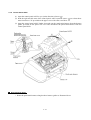
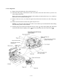
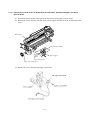
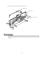
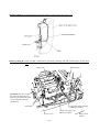
4.1.3 Bottom Plate, Ink Absorber Box, Main PCB, NCU PCB, and Power Supply PCB
(1) Disconnect the following harnesses and flat cables from the main PCB:
• Head flat cables
• Registration sensor harness
• Purge switch harness
• Ink empty sensor harness
• Panel-main harness
• CIS harness
• Scanner motor harness
• Carriage motor harness
• Paper feed motor harness
• Speaker harness*
• Hook switch harness*
*Provided in the MFC3200C/FAX1800C.
Main PCB
CIS harness
(Power supply
harness)
Main PCB
Paper feed motor harness
Ink empty sensor harness
(Paper width sensor)
Purge switch harness
Registration sensor harness
Carriage motor harness
Scanner motor harness
Speaker harness*
Panel-main harness
Hook switch harness*
Head flat cable 1
Head flat cable 2
(Rear)
4 -1 1
*Provided in the MFC3200C/FAX1800C.
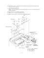
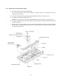
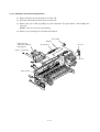
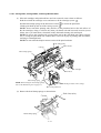
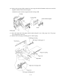
(2) Remove three screws "e" from the rear of the machine (two for the parallel I/F connector and
one for the USB I/F connector).
(3) Turn the machine upside down.
NOTE: Cover the workbench with cloth to protect the top cover and control panel from
scratches or damages.
(4) Remove nine screws "a" from the bottom plate.
(5) Remove screw "b" from the grounding terminal.
(6) Remove four screws, two "c" and two "d" from the bottom shield.
"a" and "c": Taptite, cup B M3x12
"b": Screw, pan M4x8
"d": Taptite, cup S M3x5
"e": Screw, pan M3x6
4 -1 2
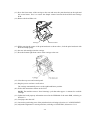
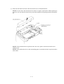
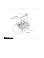
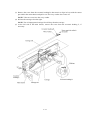
(7) Push down the latch and remove the ink absorber box as illustrated below.
NOTE: Do not remove the ink absorber box unless it requires replacement. When replacing it,
set a new one soon after the removal to prevent the machine from getting stained with drained
ink.
NOTE: If the print head unit is replaced with a new one, replace also the ink absorber box
with new one.
NOTE: If the ink absorber box or the surrounding parts are stained with ink, wipe them with a
waste cloth.
4 -1 3
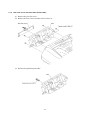
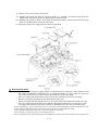
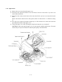
(8) Remove the screw from the FG plate R.
(9) Slightly pull up the FG plate R, pull two latches "a" outwards, and then lift up the power
supply PCB. Disconnect the power supply harness from the PCB.
(10) Slightly pull up the FG plate L and release the main PCB from it. Release the NCU PCB from
latch "b" and disconnect it from the main PCB.
(11) Disconnect the power supply harness from the main PCB.
Reassembling Notes
• Be sure to route the power supply harness as illustrated above. Route the other harnesses and
flat cables as illustrated in Subsection 4.1.22, "Harness Routing A." At the right rear corner, be
sure to hook the ferrite core of the scanner motor harness on the cable guide.
• After you replace the main PCB, be sure to follow the flowchart given on the next page.
• Be sure to route the grounding wire as illustrated on page 4-12.
• When you replace the main PCB with a new one, also replace ink absorber box with a new one.
• After you replace the ink absorber box without replacing the main PCB, reset the purge count
according to the following procedure. Otherwise, Machine Error 46 occurs at an early stage.
1) Press the [Menu], [*], [2], [8], [6] and [4] keys in this order to make the machine enter the maintenance mode.
2) Press the [8] and [0] keys in this order to show the equipment’s log information on LCD.
3) Press the [Fax Start] button nine times to show the purge count on LCD.
4) Press the [2], [7], [8] and [3] keys to reset the purge count.
5) Press the [9] key twice in the initial stage of the maintenance mode to restore the machine to the standby state.
4-14
Setting up the main PCB after replacement
- - - - - - - - - - - - - - - - - - - - - - - - - - - - - - - - - - - - - Important - - - - - - - - - - - - - - - - - - - - - - - - - - - - - - - - - - - - - - NOTE: Before starting the following procedure, make sure that the print head unit is installed.
4 -1 5
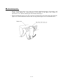
4.1.4 Enclosure Cover and Paper Width Sensor Actuator
(1) While pulling up the FG plate R, lift up the enclosure cover.
(2) Slightly push down the locking arm and remove the paper width sensor actuator as shown
below.
4 -1 6
4.1.5 Top Cover
(1) Turn the machine back to the normal position.
(2) Open the control panel ASSY.
(3) Open the top cover (not fully) and lift it up and to the rear.
4 -1 7
4.1.6 Control Panel ASSY
(1) Open the control panel ASSY to you (in the direction of arrow
).
(2) Push the right and left arms of the control panel ASSY outwards (arrow
arms from bosses "X" provided on the upper cover with a flat screwdriver.
) to release those
(3) Open the control panel ASSY further, then take out the panel-main harness from the harness
guides provided on the panel rear cover and disconnect the panel-main harness from the
control panel PCB.
Reassembling Notes
• Route the panel-main harness along the three harness guides as illustrated above.
4 -1 8
4.1.7 Panel Rear Cover and Control Panel
(1) Place the control panel ASSY upside down.
If you do not need to remove the ADF parts, antistatic brush, or document rear sensor
actuator, skip to step (5).
(2) To remove the ADF parts (spring plates and separation rubber), remove the screw.
(3) To replace the antistatic brush, peel it off.
NOTE: Once removed, it will become unusable and a new part will have to be put back in.
(4) To remove the document rear sensor actuator, pull the actuator to the left and lift up the right
end of the actuator.
(5) Pull section "b" of the panel rear cover to the front to release the center tab of the document
pressure bar, turn up the document pressure bar, and pull either end of the document pressure
bar outwards to release it.
4 -1 9
(6) Remove the two screws from the panel rear cover.
(7) Unhook the panel rear cover from ten "X" latches provided on the control panel and lift up the
panel rear cover.
(8) Fully turn the document front sensor actuator to the rear and lift it up.
(9) Unhook the control panel PCB from seven "Y" latches.
(10) Slightly lift up the control panel PCB, then unlock the LCD cable connector and disconnect
the LCD flat cable. Next, unlock the FPC key connector and disconnect the FPC key.
Taptite, cup B M3x8
Panel rear cover
Document front
sensor actuator
Cover/panel open sensor
Document front sensor
LCD
Control panel PCB
Document
rear sensor
FPC key
Piezo ringer *
10 "X" latches
(Front)
7 "Y" latches
Control panel
* Not provided in the MFC3200C/FAX1800C.
4 -2 0
(11) As shown below, pull up the locking arm "x," slide the LCD to the right, pull the locking arm
"y" to the rear, and take out the LCD while pulling the LCD flat cable gently.
Reassembling Notes
• Before reinstalling the LCD to the control panel, wipe fingerprints or dust off the LCD surface
and control panel window with a soft cloth.
• A new LCD is covered with a protection sheet. Before installing it, remove the protection sheet.
4 -2 1
4.1.8 CIS Unit
(1) Remove the screw from the CIS side spring and lift it up.
(2) Move the CIS unit to the left and lift up the right edge of the CIS unit. While holding up the
CIS unit, disconnect the CIS harness. The CIS springs also come off.
Reassembling Notes
• After installation of the CIS unit, wipe fingerprints or dust off the CIS surface with a soft cloth.
4 -2 2
4.1.9 Upper Cover
(1) Remove the two screws from the upper cover.
(2) Disconnect the panel-main harness and CIS harness from the main PCB if you have not
removed the main PCB.
(3) Disconnect the scanner motor harness from the main PCB if you have not removed the main
PCB.
Remove the harness from the four cable guides (shown in Subsection 4.1.22 "Harness routing
A."
(4) Press the cover retainers R inwards with the tip of a flat screwdriver to release the rear hooks
provided on the inside of the upper cover.
(5) Lift up the upper cover while releasing the front hooks from the cover retainers F.
CAUTION: After removing the upper cover, do not turn the machine upside down. The main
chassis may be warped or distorted so that the print quality could deteriorate.
4 -2 3
Reassembling Notes
• Before installing the upper cover, make sure that the panel-main harness, CIS harness, and
scanner motor harness are routed properly on the inside of the upper cover. (Refer to
Subsection 4.1.22 "Harness Routing B" and "Harness Routing C."
• When installing the upper cover, take care not to bring the tab of the ASF roller unit inside the
upper cover. The tab should be fitted to the rear edge of the upper cover as illustrated below.
4 -2 4
4.1.10 Document Feed Roller ASSY, Document Ejection Roller ASSY, Pressure Roller, and Pinch
Rollers
(1) Remove the two pawled plastic bushings from the left ends of the document feed roller and
document ejection roller. (Access those bushings from the inside of the upper cover.)
Move the document feed roller and document ejection roller to the right and upwards.
(2) Push two latches "a" to the rear and remove the pressure roller, its shaft and springs.
(3) Push two latches "b" to the front and remove the pinch rollers, their shaft and spring.
4 -2 5
4.1.11 Panel Lock Springs, Scanner Chassis, Separation Roller, Scanner Drive Unit, and Scanner
Motor
(1) Remove screws "a" and "b" from the panel lock springs R and L, respectively, then take those
springs out of the upper cover. (Access them from the inside of the upper cover.)
(2) Remove the scanner motor harness from the cable guides provided on the inside of the upper
cover (see Subsection 4.1.22, "Harness Routing B."
(3) Remove four screws "c" from the scanner chassis and take it out.
(4) Remove the CIS front springs.
"a": Taptite, cup S M3x5
"b" and "c": Taptite, cup B M3x10
4 -2 6
(5) Press the lock arm to the rear and move the separation roller gear.
Press the lock arm again to remove bushing 12. Then the separation roller and bushing 6.
(Access them from the inside of the upper cover.)
(6) Lift up the scanner drive unit together with the separation roller gear.
4 -2 7
(7) Remove the screw and release the scanner motor from the scanner drive unit.
Reassembling Notes
• When securing the scanner motor to the scanner drive unit, face the motor connector as shown
above.
• When setting the separation roller and its gear, first fit bushing 6 into the upper cover with its
flange facing towards the scanner drive unit and with its stopper facing down (when viewed
from the bottom), as illustrated on the previous page.
Set the separation roller. Then lightly press the lock arm and fit bushing 12 with its flange
facing towards the scanner drive unit and with its stopper facing up (when viewed from the
bottom).
Next, insert the separation roller gear shaft through bushing 12 and engage it with the
separation roller.
• Route the scanner motor harness on the inside of the upper cover as shown in Subsection
4.1.22, "Harness Routing B."
• When reinstalling the scanner chassis, make sure that the scanner motor harness is routed as
shown on page 4-26.
4 -2 8
4.1.12 Purge Unit
(1) Remove the print head unit (refer to Subsection 4.1.1).
(2) Disconnect the purge switch harness (blue and white) from the main PCB if you have not
removed the main PCB.
Remove the purge switch harness from the cable guides provided on the lower cover. (Refer to
Subsection 4.1.22 "Harness Routing A."
(3) Remove the two screws, one from the right side and the other from the rear side of the purge
unit.
(4) Remove the drain tube from the tube guide and pull it out.
NOTE: Cover the end of the drain tube with a waste cloth to prevent drained ink from leaking
out and making stains on the machine.
(5) Pull the purge unit to the front in the direction of arrow . Then while pulling the right front
end of the main chassis slightly (arrow ), pull out the purge unit to the front (arrow ).
4 -2 9
(6) Take off the purge cam HP switch and pump switching cam HP switch from the purge unit by
pulling the latches outwards, respectively.
(7) Remove the purge bevel gear A. (See the illustration given on the previous page.)
Reassembling Notes
• When installing the purge unit, be sure to insert the end of the drain tube into the hole
(provided in the lower cover) that leads to the ink absorber box.
4 -3 0
4.1.13 Main Chassis
(1) Disconnect the carriage motor harness, registration sensor harness, ink empty sensor harness,
head flat cables, and paper feed motor harness from the main PCB if you have not removed
the main PCB.
Remove those harnesses from the cable guides provided on the lower cover.
(2) Remove screw "x" from the lower end of FG plate R if you have not removed it on page 4-14.
(3) Remove screws "y" and "z" from the upper ends of FG plates R and L, respectively, then
remove those plates. Removing the FG plate L releases the head flat cables.
(4) Unhook the four latches and lift up the main chassis.
NOTE: If vibration absorbers (black rubber bushings) are left in the lower cover, pull them
out.
Carriage motor harness
FG plate R
"y"
Carriage motor
Main chassis
Ink empty sensor harness
Registration sensor harness
"z"
FG plate L
Vibration absorbers
Head flat cables
Paper feed motor harness
Latches
Vibration absorbers
Latches
Lower cover
Lower cover
Latches
FG plate L
FG plate R
"x"
Ink empty sensor harness
"x": Taptite, cup B M3x12
"y" and "z": Taptite, cup S M3x5
Reassembling Notes
• When installing the main chassis to the lower cover, make sure that the four vibration absorbers
are fitted on the bottom ends of the main chassis.
• After installing the main chassis, be sure to route the harnesses and flat cables as illustrated in
Subsection 4.1.22 "Harness Routing A."
4 -3 1
4.1.14 ASF Roller Unit and its Related Gears
(1) Remove the three screws from the rear of the ASF.
(2) Move the ASF to the left and remove it to the rear.
(3) Remove the gear 31MF by pulling its pawls outwards. The gear shaft 17 and bushing also
come off.
NOTE: Take care not to lose the bushing.
(4) Remove gear 39 and gear 25 from the main chassis.
Gear 31MF
Bushing
ASF roller unit
(ASF roller ASSY &
ASF support)
Gear shaft 17
Gear 39
Taptite, cup S M3x6
Gear 25
Main chassis
4 -3 2
Disassembly of the ASF Roller Unit
1) Pull the pawl of the ASF gear 31 outwards and pull out the gear shaft 15. The ASF roller
ASSY and the ASF gear 32 also come off.
2) Remove the screw from the ASF roller ASSY. Then it will be disassembled as shown below.
4 -3 3
4.1.15 Roller Pressure Holders
(1) At each of the paper pressure holders, unhook the top end of the spring from the main chassis.
(2) Remove the roller pressure holders.
Paper pressure holder R
Paper pressure holders M
Springs
Paper pressure
holder L
Main chassis
Reassembling Notes
• When replacing films on the paper pressure holders with new ones, attach them as illustrated
below.
4 -3 4
4.1.16 Paper Chute and Registration Sensor
(1) Remove the screw from the rear of the paper chute and take it off from the main chassis.
Paper chute
Taptite, cup S
M3x6
Main chassis
4 -3 5
(2) Unhook the registration sensor.
(3) Unhook the actuator spring.
(4) Push the lock arm and slide the sensor actuator in the direction of arrows
4 -3 6
and
.
4.1.17 Paper Ejection Roller Gear, Ink Empty Sensor PCB, Platen, Star Wheel Support, and Paper
Ejection Roller
(1) Pull out the paper ejection roller gear from the left end of the paper ejection roller.
(2) Remove the screw from the left side of the sensor support and take it off in the direction of the
arrow.
Main chassis
Ink empty sensor PCB
Locks
Taptite,
cup S
M3x6
Sensor support
Paper ejection joint
Paper ejection roller gear
(3) Remove the screw from the ink empty sensor PCB.
4 -3 7
(4) Remove the screws from the platen and pull it out in the direction of the arrow.
NOTE: Take care not to touch the flushing sponge that is impregnated with ink.
4 -3 8
(5) Unhook the four latches of the star wheel support and separate it from the platen.
(6) Remove star wheels A and B from the star wheel support.
(7) Pull out the paper ejection joint from the left end of the paper ejection roller.
(8) Remove the pawled bushing by pulling its pawls outwards.
(9) Remove the paper ejection roller and bushing (white).
(10) Remove the screw from each of the right and left platen plates.
4 -3 9
4.1.18 Paper Feed Motor and Paper Feed Roller
(1) Remove the paper feed motor by removing the two screws.
(2) Remove the crescent ring from the PF roller gear and pull out the gear.
(3) Unhook the PF spring.
(4) Turn the PF bushings as shown below and disengage them from the main chassis. Then
remove the paper feed roller.
NOTE: When disengaging PF bushing R, slide the ASF/purge idle gear outwards.
NOTE: When removing the right end of the paper feed roller from the main chassis, move the
carriage to the left; when removing the left end, move it to the right.
(5) Remove the retaining ring from the PF idle gear, then pull out the gear and its spring.
Paper feed roller
PF bushing R
Color marking
(red or blue)
PF spring
ASF/purge idle gear
PF
bushing L
PF roller gear
Carriage
Crescent ring
Retaining ring
Screw, pan
(s/p washer)
M3x6
PF idle gear
Idle gear spring
Paper feed motor
Reassembling Notes
• When replacing the paper feed roller, check the color marking (shown above) made on the
current roller and use a new roller having the same color marking.
• When setting the PF spring into place, hook the looped end on the main chassis and the open
end on the paper feed roller with its edge facing down.
• When installing the paper feed motor, face the connector towards the rear. When tightening the
two screws, take care not to scratch the paper feed roller with a screwdriver.
• When fitting the PF roller gear over the left end of the paper feed roller, do not set it at an
angle. Take care not to damage the gear teeth.
4 -4 0
4.1.19 Encoder Strip and Carriage Motor
(1) At the left end of the encoder strip, unhook the spring from the main chassis.
NOTE: Take care not to scratch or damage the encoder strip.
This should point up.
Encoder strip
150
C16
Main chassis
Carriage motor pulley
Encoder strip
spring
"c"
Main chassis
Pulley
"b" "a" spring
Idle pulley holder
Strip guide
Carriage
Encoder strip
"a": Screw, pan (s/p washer) M3x8
"b": Shoulder screw
"c": Taptite, cup S M3x6
(2) Move the carriage to the center of its travel.
(3) Loosen two screws "a" and "c" on the idle pulley holder. (See the above illustration.)
(4) While pushing the idle pulley holder to the right, remove the timing belt from the carriage
motor pulley and idle pulley.
4 -4 1
(5) Remove the carriage motor by removing the two screws.
Carriage motor
Main chassis
Screw, pan (s/p washer)
M3x6
Reassembling Notes
• Pass the encoder strip through the strip guide provided on the back of the carriage so that the
encoder strip will route as illustrated on the previous page and the ▲-marked end comes to the
left. Then hook the ▲-marked end on the spring hooked on the main chassis so that the ▲ mark
points up.
4 -4 2
4.1.20 Carriage Rail, Carriage ASSY, and Purge-Related Parts
(1) If the ink cartridges and print head have not been removed, remove them as follows:
Push the colored ink cartridge covers and remove all ink cartridges (arrow
Pull the head clamp springs in the direction of arrow
).
to release the print head.
Lift the print head up and out of the carriage (arrow ).
NOTE: Do not touch the printing ends (nozzles) of the print head unit or the ink orifices of
the ink cartridges; doing so will not only stain your hands with ink but result in an ink jet-out
failure. Once you touch them, clean them with a dedicated cleaning stick and liquid.
NOTE: Be sure to put a head nozzle seal and filter seal on the print head unit (shown on page
4-6). Leaving the print head unit without those seals will dry up its printing ends and filters,
resulting in a damaged head.
NOTE: Do not touch the dimple contact section of the print head unit.
Head clamp spring
Main chassis
Carriage
Head clamp spring
Ink cartridges
Print head
Head clamp spring
NOTE: When setting the head clamp springs,
refer to the illustration given on page 4-6.
Locks provided on the carriage
Boss of the print head
(2) Remove the head clamp springs as shown below.
4 -4 3
(3) Remove the screw from the eccentric bushing R, then turn it to align its boss with the cutout
provided in the main chassis and pull it out. The wavy washer also comes off.
NOTE: Take care not to lose the wavy washer.
(4) Pull out the carriage rail to the right.
NOTE: The oil-impregnated carriage felt will drop from the carriage.
(5) At the left side of the main chassis, remove the screw from the eccentric bushing L, if
necessary.
4 -4 4
(6) From the rear side of the main chassis, remove the cable clamp stopper that is attached with
double-sided adhesive tape. From the front side, unlatch the flat cable clamp to release the
head flat cables.
(7) Remove the FFC clamp film from the left end of the main chassis.
(8) Remove tapes from the flat cable guide. The carriage is now completely separated from the
main chassis.
(9) Remove the timing belt from the back of the carriage.
4 -4 5
(10) Push up the carriage PCB to unhook its lower edge from the PCB holders and remove the PCB
together with the sensor actuator support.
Unlatch the sensor actuator support from the carriage PCB.
(11) Press the right end of the purge shaft inwards and pull it out of the purge lever. The purge
lever spring also comes off.
(12) Remove the ASF-purge switching gear 23 and its spring.
4 -4 6
Reassembling Notes
• To install the carriage rail, temporarily set the eccentric bushing L to the left side of the main
chassis with the screw, align the bushing L with marking made on the main chassis, and then
tighten the screw firmly.
Pass the carriage rail through the opening in the right side of the main chassis and through the
carriage, then fit it into the eccentric bushing L.
Next, fit the eccentric bushing R over the right end of the carriage rail, temporarily set the
bushing R to the right side of the main chassis with the screw, align the bushing R with marking
made on the main chassis, and then tighten the screw firmly.
This alignment with markings is required for keeping the head-platen gap properly.
• When setting the head clamp springs, refer to the illustration given on page 4-6.
• If you replace the carriage ASSY, be sure to correct the positioning error of the print head unit.
(Refer to Section 4.3 "ADJUSTMENT.")
4 -4 7
4.1.21 Flushing Box
(1) From the bottom, insert the tip of a flat screwdriver to unhook the latch and then slide the
flushing box to the front and upwards.
4 -4 8
4.1.22 Harness Routing
Harness routing A: Main PCB-related harnesses
Harness routing B: Scanner motor harness on the inside of the upper cover
4 -4 9
Harness routing C: Panel-main harness and CIS harness on the inside of the upper cover
Harness routing D: Purge cam HP switch harness and pump switching cam HP switch harness on the lower
cover
(Purge unit)
(Main chassis)
CAUTION: Be sure to insert
the end of the drain tube into
this hole (provided in the lower
cover) that leads to the ink
absorber box.
Drain tube
Leads of the pump switching
cam HP switch (blue)
Leads of the purge cam
HP switch (white)
(Lower cover)
4 -5 0
Purge switch
harness
4.2 LUBRICATION
Apply the specified lubricants to the lubrication points as shown below.
Lubricant amount
Lubricant type
(Manufacturer)
Thin coat of
grease with
a brush
1/4 sesame-sized Sesame-sized Rice-sized pinch Bean-sized
pinch of grease pinch of grease
pinch of grease
of grease
(0.5 mm dia. ball) (2 mm dia. ball) (3 mm dia. ball) (4 mm dia. ball)
Molykote
EM-30LG or
EM-30L
(Dow Corning)
–––––––
EM0.1
Molykote
EM-50LS
(Dow Corning)
–––––––
–––––––
–––––––
EML1
EML2
P0.02
–––––––
–––––––
–––––––
–––––––
Conductive grease
FLOIL 951P-32
(Kanto Kasei Ltd.)
[1]
Separation roller and its gear
*EM-30L (Not EM-30LG)
4 -5 1
[2]
ASF roller unit
[3]
Paper ejection roller and platen
Star wheel A
Star wheel support
EM0.1
EM0.1
Apply EM0.1 to a total of 16 points on
the star wheel support.
Platen
EM1
EM0.5
Paper ejection roller
EM0.5
EM0.5
EM0.5
4 -5 2
[4]
Paper ejection roller gear and PF roller gear
[5]
Paper feed roller and PF spring
4 -5 3
[6]
Carriage rail
Apply a thin coat of grease to the right and left edges of the carriage rail with a brush.
P0.02
Carriage rail
P0.02
Carriage
[7]
Main chassis (slideway of the carriage guide)
4 -5 4
[8]
Purge shaft
4 -5 5
4.3 ADJUSTMENT
Correcting the positioning error of the print head
Once the print head or carriage is removed, you need to correct the positioning error of the print
head according to the procedure given below. The head nozzle columns should be perpendicular to
the carriage travel path.
NOTE: This adjustment procedure requires a PC and the specified test chart data.
(1) Make sure that your PC is turned off.
(2) Make sure that the machine's power cord is unplugged from a wall socket or other power
source.
(3) Connect the machine to your PC as follows:
Connect the parallel interface cable to the parallel port on the back of the machine and secure
it with the lock wires.
Connect the other end of the interface cable to the printer port of your PC and secure it with
the two screws.
(4) Plug the machine's power cord into a wall socket or other power source. Then open the control
panel and top cover.
(5) Turn on your PC.
(6) Make sure that:
- the print head is secured to the carriage by the head clamp springs,
- the ink cartridges are set into place, and
- paper is loaded in the ASF.
(7) Turn the head adjuster lever located on the right side of the carriage to position 1. (See the
illustration given below.)
(8) Press the bottom right front corner of the print head to the rear to fit the eccentric section of
the print head over the inside boss of the head adjuster lever.
2
3
4
5
1
Head adjuster lever
(9) Close the top cover and control panel.
4 -5 6
(10) From your PC, send the specified test chart to the machine to print it out.
(11) Check the printed test patterns 1 though 5 (see the test pattern sample given on the next page)
and choose one that has the least uneven print (Pattern 1 in this sample). Make a note of the
pattern number.
(12) Press the Ink key on the machine's control panel to place it in the ink replacement mode.
The carriage automatically moves to the ink replacement position.
(13) Open the control panel and top cover.
(14) Turn the head adjuster lever to the position indicated by the pattern number you recorded in
step (11).
NOTE: Always turn the head adjuster lever in an ascending order. If you want to set the head
adjuster lever to position 3, for example, turn it from 1 to 3. Once you have turned it to
position 4, you need to turn it back to position 1 and then turn it to 3.
(15) Close the top cover and control panel.
4 -5 7
Head Positioning Test Pattern
4 -5 8
CHAPTER 5
MAINTENANCE MODE
CHAPTER 5 MAINTENANCE MODE
CONTENTS
5.1
ENTRY INTO THE MAINTENANCE MODE ....................................................................5-1
5.2
LIST OF MAINTENANCE-MODE FUNCTIONS ..............................................................5-2
5.3
DETAILED DESCRIPTION OF MAINTENANCE-MODE FUNCTIONS ..........................5-4
5.3.1
EEPROM Parameter Initialization .................................................................................... 5-4
5.3.2
Printout of Scanning Compensation Data ........................................................................ 5-5
5.3.3
ADF Performance Test..................................................................................................... 5-7
5.3.4
Test Pattern 1................................................................................................................... 5-8
5.3.5
Firmware Switch Setting and Printout .............................................................................. 5-9
5.3.6
Operational Check of LCD ............................................................................................. 5-12
5.3.7
Operational Check of Control Panel PCB....................................................................... 5-13
5.3.8
Receiver Volume Adjustment (Applicable to the MFC3200C/FAX1800C) ..................... 5-15
5.3.9
Sensor Operational Check ............................................................................................. 5-16
5.3.10 Fine Adjustment of Scanning Start/End Position............................................................ 5-17
5.3.11 CIS Scanner Area Setting .............................................................................................. 5-18
5.3.12 Setting the Sensing Reference Level of the Ink Empty Sensor...................................... 5-19
5.3.13 Alignment of Vertical Print Lines .................................................................................... 5-20
5.3.14 Updating of Head Property Information .......................................................................... 5-22
5.3.15 Initial Adjustment of PWM Value (Aging of the Carriage)............................................... 5-23
5.3.16 EEPROM Customizing ................................................................................................... 5-24
5.3.17 Display of the Equipment's Log Information ................................................................... 5-25
5.3.18 Equipment Error Code Indication ................................................................................... 5-26
5.3.19 Output of Transmission Log to the Telephone Line ....................................................... 5-26
5.3.20 Cancellation of the Pin TX Lock Mode (Not applicable to American models) ................ 5-27
5.1 ENTRY INTO THE MAINTENANCE MODE
To make the facsimile equipment enter the maintenance mode, press the Menu,
*, 2, 8, 6, and 4 keys in this order.
Within 2 seconds
The equipment beeps for approx. one second and displays "
" on the
LCD, indicating that it is placed in the initial stage of the maintenance mode, a mode in which the
equipment is ready to accept entry from the keys.
To select one of the maintenance-mode functions listed in Section 5.2, enter the corresponding 2digit function code with the numerical keys on the control panel. (The details of each maintenancemode function are described in Section 5.3.)
NOTES: • Pressing the 9 key twice in the initial stage of the maintenance mode makes the equipment
exit from the maintenance mode, restoring it to the standby state.
• Pressing the Stop key after entering only one digit restores the equipment to the initial
stage of the maintenance mode.
• If an invalid function code is entered, the equipment resumes the initial stage of the
maintenance mode.
5 -1
5.2 LIST OF MAINTENANCE-MODE FUNCTIONS
Maintenance-mode Functions
01
EEPROM Parameter Initialization
Reference
Subsection
(Page)
5.3.1 (5-4)
05
Printout of Scanning Compensation Data
5.3.2 (5-5)
08
ADF* Performance Test
5.3.3 (5-7)
09
Test Pattern 1
5.3.4 (5-8)
10
Firmware Switch Setting
5.3.5 (5-9)
11
Printout of Firmware Switch Data
5.3.5 (5-11)
12
Operational Check of LCD
5.3.6 (5-12)
13
Operational Check of Control Panel PCB
(Check of Keys and Buttons)
5.3.7 (5-13)
16
Receiver Volume Adjustment (Applicable to the MFC3200C/
FAX1800C)
5.3.8 (5-15)
32
Sensor Operational Check
5.3.9 (5-16)
54
Fine Adjustment of Scanning Start/End Position
5.3.10 (5-17)
55
CIS Scanner Area Setting
5.3.11 (5-18)
57
Setting the Sensing Reference Level of the Ink Empty Sensor
5.3.12 (5-19)
65
Alignment of Vertical Print Lines
5.3.13 (5-20)
68
Updating of Head Property Information
5.3.14 (5-22)
69
Initial Adjustment of PWM Value (Aging of the carriage)
5.3.15 (5-23)
74
EEPROM Customizing
5.3.16 (5-24)
80
Display of the Equipment's Log Information
5.3.17 (5-25)
82
Equipment Error Code Indication
5.3.18 (5-26)
87
Output of Transmission Log to the Telephone Line
5.3.19 (5-26)
91
EEPROM Parameter Initialization (except the telephone
number storage area)
5.3.1 (5-4)
99
Exit from the Maintenance Mode
----- (5-1)
—
Cancellation of the Pin TX Lock Mode (Not applicable to the
American models)
5.3.20 (5-27)
Function
Code
Function
* ADF: Automatic document feeder
5 -2
- - - - - - - - - - - - - - - - - - - - - - - - - - IMPORTANT - - - - - - - - - - - - - - - - - - - - - - - - - - - - - - Basically, the maintenance-mode functions listed on the previous page should be accessed by
service personnel only. However, you may allow end users to access some of these under the
guidance of service personnel (e.g., by telephone).
The user-accessible functions (codes 10, 11, 12, 54, 65, 80, 82, 87 and 91) are shaded in the table
given on the previous page. Function code 10 accesses the firmware switches, each of which has
eight selectors. You should not allow end users to access all of those selectors, but you may allow
them to access user-accessible selectors which are shaded in the firmware switch tables in
Appendix 2.
The service personnel should instruct end users to follow the procedure given below.
(1) American models: Press the Menu and Receive Mode keys in this order.
European models: Press the Menu and Tel/R keys in this order.
The LCD clears the current display.
NOTE: The Receive Mode or Tel/R key is disabled during standby for redialing and timer.
(2) Press the 0 key.
(3) Enter the desired function code (10, 11, 12, 54, 65, 80, 82, 87, or 91) with the numerical keys.
For function code 10, access the desired firmware switch according to the operating procedure
described in Appendix 2.
(4) To make the equipment return to the standby state, press the Stop key.
Stop key
0 key
5 -3
Menu key
Receive Mode (Tel/R) key
5.3 DETAILED DESCRIPTION OF
MAINTENANCE-MODE FUNCTIONS
5.3.1 EEPROM Parameter Initialization
Function
The equipment initializes the parameters, user switches, and firmware switches registered in the
EEPROM, to the initial values. Entering the function code 01 initializes almost all of the
EEPROM areas, but entering 91 does not initialize some areas, as listed below.
Function code
01
Data item
Maintenance-mode functions
User switches
Firmware switches
Remote activation code
These will be
initialized
Activity report
Station ID data
Outside line number
Telephone function registration
One-touch dialing
Speed dialing
Group dialing
EEPROM customizing code
(4-digit)
91
All of these will be.
initialized
These will not be
initialized
This will not be initialized.
(Note that the first digit of the 4-digit code will be
initialized to "0." If the code is 1001, for example, it
will be initialized to 0001.)
NOTE: you replace the main PCB with one used for other facsimile equipment, carry out this
procedure and then customize the EEPROM (maintenance-mode function code 74 in Section
5.3.16).
Operating Procedure
(1) Press the 0 and 1 keys (or the 9 and 1 keys according to your need) in this order in the initial
stage of the maintenance mode.
The "PARAMETER INIT" will appear on the LCD.
(2) Upon completion of parameter initialization, the equipment returns to the initial stage of the
maintenance mode.
5 -4
5.3.2 Printout of Scanning Compensation Data
Function
The equipment prints out the white and black level data for scanning compensation.
Operating Procedure
Do not start this function merely after powering on the equipment but start it after carrying out a
sequence of scanning operation. Unless the equipment has carried out any scanning operation, this
function cannot print out correct scanning compensation data. This is because at the start of
scanning operation, the equipment initializes white and black level data and takes in the scanning
compensation reference data.
(1) Press the 0 and 5 keys in this order in the initial stage of the maintenance mode.
The "WHITE LEVEL 1" will appear on the LCD.
(2) The equipment prints out the scanning compensation data list containing the following:
a)
b)
c)
d)
e)
f)
g)
h)
i)
j)
k)
l)
LED PWM data for color print (1 byte)
LED PWM data for monochrome print (1 byte)
Green LED pulse data (2 bytes)
Blue LED pulse data (2 bytes)
Red LED pulse data (2 bytes)
A/D converter reference level for high value (1 byte)
A/D converter reference level for low value (1 byte)
Compensation data for background color (1 byte)
Black level data (2448 bytes)
White level data for red image (2464 bytes)
White level data for green image (2464 bytes)
White level data for blue image (2464 bytes)
(3) Upon completion of recording of the compensation data list, the equipment returns to the
initial stage of the maintenance mode.
NOTE: When the equipment prints monochrome images after monochrome scanning, only the
green data is valid.
NOTE: If any data is abnormal, its code will be printed in inline style, as shown on the next page.
5 -5
Scanning Compensation Data List
5 -6
5.3.3 ADF Performance Test
Function
The equipment counts the documents fed by the automatic document feeder (ADF) and displays
the count on the LCD for checking the ADF performance.
Operating Procedure
(1) Set documents. (Allowable up to the ADF capacity.)
The "DOC. READY" will appear on the LCD.
(2) Press the 0 and 8 keys in this order.
While counting the documents, the equipment feeds them in and out, displaying the current
count on the LCD as shown below.
Current count (1st page in this example)
(3) After counting all documents, the equipment shows the final count. To return the equipment to
the initial stage of the maintenance mode, press the Stop key.
5 -7
5.3.4 Test Pattern 1
Function
This function, much like the copying function, prints out test pattern 1 to allow the service
personnel to check for record data missing or print quality.
Operating Procedure
Press the 0 and 9 keys in this order in the initial stage of the maintenance mode.
The figure below shows test pattern 1.
Test Pattern 1
5 -8
5.3.5 Firmware Switch Setting and Printout
[ A ] Firmware switch setting
Function
The facsimile equipment incorporates the following firmware switch functions which may be
activated with the procedures using the control panel keys and buttons.
The firmware switches have been set at the factory in conformity to the communications standards
and codes of each country. Do not disturb them unless necessary. Some firmware switches may not
be applicable in some versions. The firmware switch data list indicates "Not used." for those
inapplicable switches.
Firmware Switches (WSW01 through WSW50)
WSW No.
WSW01
WSW02
WSW03
WSW04
WSW05
WSW06
WSW07
WSW08
WSW09
WSW10
WSW11
WSW12
WSW13
WSW14
WSW15
WSW16
WSW17
WSW18
WSW19
WSW20
WSW21
WSW22
WSW23
WSW24
WSW25
WSW26
WSW27
WSW28
WSW29
WSW30
WSW31
WSW32
WSW33
Function
Dial pulse setting
Tone signal setting
PABX mode setting
TRANSFER facility setting
1st dial tone and busy tone detection
Pause key setting and 2nd dial tone detection
Dial tone setting 1
Dial tone setting 2
Protocol definition 1
Protocol definition 2
Busy tone setting
Signal detection condition setting
Modem setting
AUTO ANS facility setting
REDIAL facility setting
Function setting 1
Function setting 2
Function setting 3
Transmission speed setting
Overseas communications mode setting
TAD setting 1
ECM and copy resolution setting
Communications setting
TAD setting 2
TAD setting 3
Function setting 4
Function setting 5
Function setting 6
Function setting 7
Not used.
Function setting 9
Function setting 10
Function setting 11
5 -9
Firmware Switches (WSW01 through WSW50) Continued
WSW No.
WSW34
WSW35
WSW36
WSW37
WSW38
WSW39
WSW40
WSW41
WSW42
WSW43
WSW44
WSW45
WSW46
WSW47
WSW48
WSW49
WSW50
Function
Function setting 12
Not used.
Function setting 14
Function setting 15
Not used.
Not used.
Not used.
Not used.
Function setting 20
Function setting 21
Not used.
Not used.
Monitor of power ON/OFF state and parallel port kept at high
Paper handling for a feed error and delay of FAX line disconnection
Not used.
Not used.
Not used.
Operating Procedure
(1) Press the 1 and 0 keys in this order in the initial stage of the maintenance mode.
The equipment displays the "WSW00" on the LCD and becomes ready to accept a firmware
switch number.
(2) Enter the desired number from the firmware switch numbers (01 through 50).
The following appears on the LCD:
Selector 1
↓
Selector 8
↓
WSWXX = 0 0 0 0 0 0 0 0
(3) Use the right and left arrow keys to move the cursor to the selector position to be modified.
(4) Enter the desired number using the 0 and 1 keys.
(5) Press the Set key. This operation saves the newly entered selector values onto the EEPROM
and readies the equipment for accepting a firmware switch number.
(6) Repeat steps (2) through (5) until the modification for the desired firmware switches is
completed.
(7) Press the Set or Stop key to return the equipment to the initial stage of the maintenance mode.
NOTES: • To cancel this operation and return the equipment to the initial stage of the
maintenance mode during the above procedure, press the Stop key.
• If there is a pause of more than one minute after a single-digit number is entered for
double-digit firmware switch numbers, the equipment will automatically return to the
initial stage of the maintenance mode.
Details of Firmware Switches
The details of the firmware switches are described in Appendix 2 in which the user-accessible
selectors of the firmware switches are shaded.
5 -1 0
[ B ] Printout of firmware switch data
Function
The equipment prints out the setting items and contents specified by the firmware switches.
Operating Procedure
(1) Press the 1 key twice in the initial stage of the maintenance mode.
The "PRINTING" will appear on the LCD.
(2) The equipment prints out the configuration list as shown in the figure below.
(3) Upon completion of printing, the equipment returns to the initial stage of the maintenance
mode.
Configuration List
5 -1 1
5.3.6 Operational Check of LCD
Function
This function allows you to check whether the LCD on the control panel works normally.
Operating Procedure
(1) Press the 1 and 2 keys in this order
in the initial stage of the
maintenance mode.
The LCD shows the screen given at
right.
(2) Press the Black Fax Start key. Each
time you press the Black Fax Start
key, the LCD cycles through the
displays shown at right.
(3) Press the Stop key in any process of the above display cycle. The equipment beeps for one
second and returns to the initial stage of the maintenance mode.
5 -1 2
5.3.7 Operational Check of Control Panel PCB
Function
This function allows you to check the control panel PCB for normal operation.
Operating Procedure
(1) Press the 1 and 3 keys in this order in the initial stage of the maintenance mode.
The "00
" will appear on the LCD.
(2) Press the keys and buttons in the order designated in the illustration shown below.
The LCD shows the corresponding number in decimal notation each time a key or button is
pressed. Check that the displayed number is correct by referring to the illustration below.
If a key or button is pressed out of order, the equipment beeps and displays the "INVALID
OPERATE" on the LCD. To return to the status ready to accept key & button entry for
operational check, press the Stop key.
(3) After the last number key or button is pressed, the equipment beeps and returns to the initial
stage of the maintenance mode.
To terminate this operation, press the Stop key. The equipment returns to the initial stage of
the maintenance mode.
MFC3100C/MFC580
Key & Button Entry Order (1)
5 -1 3
MFC3200C/FAX1800C
13
2
1
3
10
6
16
17
18
19
20
21
11
8
9
23
12
31
Key & Button Entry Order (2)
35
34
24
27
5 -1 4
29
32
25
26
22
7
30
15
28
4
5
14
33
36
5.3.8 Receiver Volume Adjustment (Applicable to the MFC3200C/FAX1800C)
Function
The HIGH level of the handset receiver's volume will be influenced by the characteristics of the
FET on the main PCB, so it requires fine adjustment according to the procedure given below.
Operating Procedure
(1) Connect the telephone line cord to the modular jack of the facsimile equipment and the
telephone wall socket.
(2) Pick up the handset and listen to the dial tone. If the receiver volume is not appropriate,
proceed to the following steps:
(3) Press the 1 and 6 keys in this order in the initial stage of the maintenance mode.
The LCD shows the current receiver volume (default: HIGH).
(4) If the current receiver volume is not HIGH, use the right or left arrow key to choose HIGH.
(5) Press the Start key.
The equipment enters the receiver volume adjustment mode and shows the PWM duty ratio at
the right end of the LCD.
(6) Adjust the receiver volume by using the 1, 3, 4, or 6 key.
1 key: Decrease 10H
3 key: Increase 10 H
4 key: Decrease 1H
6 key: Increase 1H
(7) To escape from the receiver volume adjustment mode, press the Set key.
The LCD shows the "PWM SETTING." One second later, the LCD returns to the screen
shown in step (3).
(8) To return the equipment to the initial stage of the maintenance mode, press the Stop key.
5 -1 5
5.3.9 Sensor Operational Check
Function
This function allows you to check the following:
-
Document front sensor
Document rear sensor
Cover/panel open sensor
Registration sensor
Paper width sensor
Purge cam HP switch
Pump switching cam HP switch
-
Head dimple contact
Black ink cartridge sensor
Yellow ink cartridge sensor
Cyan ink cartridge sensor
Magenta ink cartridge sensor
Head driver chip temperature sensors
Hook switch*
(*Provided in the MFC3200C/FAX1800C)
Operating Procedure
(1) Press the 3 and 2 keys in this order in the initial stage of the maintenance mode. The
equipment sounds 1100 Hz and 400 Hz tones cyclically through the following volumes for
testing the speaker:
NOTE: To stop beeping, press the Menu key.
If the sensing status are as listed below, the LCD will show the following two letter strings
which can be switched by pressing the Black Fax Start key:
MFC3100C/MFC580: "DFDRCVRSPWP1P2HD" and "IKIYICIMVT"
MFC3200C/FAX1800C: "HKDFDRCVRSPWHDVT" and "P1P2IKIYICIM"
Given below is the relationship between the LCD indication, sensor name and sensor status.
LCD
HK
DF
DR
CV
RS
PW
P1
P2
HD
IK
IY
IC
IM
VT
Sensors
Hook switch*
Document front sensor
Document rear sensor
Cover/panel open sensor
Registration sensor
Paper width sensor
Purge cam HP switch
Pump switching cam HP switch
Head dimple contact
Black ink cartridge sensor
Yellow ink cartridge sensor
Cyan ink cartridge sensor
Magenta ink cartridge sensor
Head driver chip temperature sensors
Sensing status
On-hook state.
No document detected.
No document detected.
Top cover and control panel ASSY closed.
No recording paper detected.
No paper detected.
Purge cam placed in the home position.
Pump switching cam placed in the home position.
Head detected.
Black ink cartridge loaded.
Yellow ink cartridge loaded.
Cyan ink cartridge loaded.
Magenta ink cartridge loaded.
Driver chip temperature within the allowable range
(2) Change the detecting conditions (e.g., pick up the handset*, insert paper through the document
sensors, registration sensor or paper width sensor, open the top cover or control panel ASSY,
and remove the print head or ink cartridges) and then check that the indication on the LCD
changes according to the sensor states.
(3) To stop this operation and return the equipment to the initial stage of the maintenance mode,
press the Stop key.
5 -1 6
5.3.10 Fine Adjustment of Scanning Start/End Position
Function
This function allows you to adjust the scanning start/end position.
Operating Procedure
(1) Press the 5 and 4 keys in this order in the initial stage of the maintenance mode.
The "SCAN START ADJ." appears on the LCD. After two seconds, the current scanning
position correction value appears.
You may adjust the correction value to 11 levels from +5 to -5 (mm).
(2) To increase the correction value, press the left arrow key; to decrease it, press the right arrow
key.
If you press the Stop key, the equipment returns to the initial stage of the maintenance mode
without making change of the correction value.
(3) Press the Set key.
The "ACCEPTED" appears on the LCD. After one second, the equipment returns to the initial
stage of the maintenance mode.
NOTE: The relationship between
the scanning start/end positions
and their correction values is
shown below.
Right arrow key
Left arrow key
5 -1 7
5.3.11 CIS Scanner Area Setting
Function
The equipment sets the CIS scanner area and stores it into the EEPROM.
Operating Procedure
(1) Press the 5 key twice in the initial stage of the maintenance mode.
The "SCANNER AREA SET" will appear on the LCD.
The equipment checks and sets the area to be scanned.
If no error is noted, the equipment returns to the initial stage of the maintenance mode.
If any error is noted, the "SCANNER ERROR" will appear on the LCD. To return the
equipment to the initial stage of the maintenance mode, press the Stop key.
5 -1 8
5.3.12 Setting the Sensing Reference Level of the Ink Empty Sensor
Function
This function allows you to set the sensing reference level of the ink empty sensor which apply
when the controller judges whether there is ink in the ink cartridge. The setting procedure requires
a foam-empty cartridge as a reference cartridge.
NOTE: If you replace the main PCB or ink empty sensor, carry out this procedure.
Operating Procedure
Handling notes for the reference cartridge: Shown below is a foam-empty cartridge to be used
for setting the sensing reference level of the ink empty sensor. Do not touch section "x" or "y."
If any dust or dirt is found on "x" or "y," wipe it off with a soft cloth. If "x" is scratched, replace
the cartridge with a new one. Using such a scratched cartridge will fail to set correct reference
level. After completion of the setting procedure, store the cartridge in the container.
Foam-empty cartridge
(1) Press the 5 and 7 keys in this order in the initial stage of the maintenance mode.
(2) Open the control panel and top cover.
The carriage automatically moves left to the ink replacement position.
(3) Remove the yellow ink cartridge.
The LCD shows "SET F.EMP CART!!."
NOTE: When this message is displayed, do not load or unload any other ink cartridges.
(4) Set the foam-empty cartridge into the yellow ink cartridge position.
The LCD shows "CLOSE COVER!!."
(5) Close the top cover and control panel.
The equipment shows the "-INKEMP CHECK-" and starts setting the sensing level for the
foam-empty cartridge.
If the equipment completes setting normally, it beeps and displays the "INKEMP TST:OK!."
If it fails, the "INKEMP F.EMP:NG!" appears, so press the Stop key and go back to step (1).
(6) Open the control panel and top cover, and remove the foam-empty cartridge.
(7) Load the yellow ink cartridge removed in step (3) back into place.
(8) Press the Stop key to return to the initial stage of the maintenance mode.
5 -1 9
5.3.13 Alignment of Vertical Print Lines
Function
This function allows you to align vertical lines printed in the forward and backward direction of
the carriage.
NOTE: Before this alignment job, be sure to correct the positioning error of the print head. Refer
to CHAPTER 4, Section 4.3 "ADJUSTMENT."
Operating Procedure
(1) Press the 6 and 5 keys in this order in the initial stage of the maintenance mode.
The equipment prints out a set of vertical alignment check patterns which consist of No. 1 to
No. 9 lines for each of the 600 dpi and 1200 dpi.
If the vertical alignment is ON, No. 5 line (each in the 600 dpi and 1200 dpi printouts) shows
vertically aligned lines as given on the next page.
The LCD shows the "600DPI NO.(1-9)."
(2) Check the printed vertical alignment check patterns for the 600 dpi and find which number
line shows full alignment. If the line is other than No. 5, enter that line number by using the
numerical keys.
The LCD shows the "1200DPI NO.(1-9)."
(3) For the 1200 dpi, perform the same operation as in step (2).
The equipment automatically returns to the initial stage of the maintenance mode.
NOTE: If No. 1 line or No. 9 line is fully aligned so that you press the 1 or 9 key in the above
procedure, then go back to step (1) to confirm that No. 5 line becomes aligned.
5 -2 0
Vertical Alignment Check Pattern
5 -2 1
5.3.14 Updating of Head Property Information
Function
To keep the print quality, the controller optimizes the head drive strength, ink jet-out timing, and
other drive conditions according to the electromechanical properties unique to individual print
heads and ambient temperature. The head property information is stored in the EEPROM of the
main PCB.
If you replace the print head unit and/or main PCB of the machine, then you need to update the
head property according to the procedure given here.
TIP: You may update the head property information from a PC connected to the facsimile
machine. For the procedure, refer to CHAPTER 2, Section 2.3.
Operating Procedure
(1) Press the 6 and 8 keys in this order in the initial stage of the maintenance mode.
(2) Press the 2, 5, 8, 0 keys in this order.
The facsimile machine shows the current head property information (13-digit code, e.g.,
45352DABB485F) stored in the EEPROM on the LCD and becomes ready to accept entry.
(3) Check the head property code printed on the bar code label attached to the print head unit. Out
of the 13-digit property code (enclosed with asterisks, e.g., *66667F657031H*), type upper
12 digits (e.g., 66667F657031).
NOTE: To enter letters "A" through "F," press the 1 through 6 keys while holding down the #
key, respectively.
(4) Press the Set key.
The machine beeps, shows the "INPUT ACCEPTED" on the LCD, and writes the entered
property code into the EEPROM. Then the machine returns to the initial stage of the
maintenance mode.
NOTE: If the entered data contains any checksum error, the machine beeps, shows the
"INPUT ERROR," and then returns to the ready-to-enter state. Go back to step (3).
5 -2 2
5.3.15 Initial Adjustment of PWM Value (Aging of the Carriage)
Function
This function obtains the initial value of the PWM by aging the carriage and writes it onto the
EEPROM, as well as checking the head drive voltage level.
This aging procedure should be performed if you replace the print head, carriage ASSY, carriage
motor, or encoder strip or if you loosen the timing belt.
NOTE: Opening the top cover or the control panel during the aging procedure will result in an
error. If you perform this aging procedure with either of them opened, the equipment will slowly
age the carriage resulting in an error after completion of the aging.
Operating Procedure
(1) Press the 6 and 9 keys in this order in the initial stage of the maintenance mode.
The equipment starts aging the carriage, showing the "CR AGING" on the LCD.
After writing the initial value of the PWM onto the EEPROM and checking the head drive
voltage level, the equipment automatically returns to the initial stage of the maintenance
mode.
If any error occurs, the equipment beeps and shows some message, e.g., "OK30 NG15 NG07"
on the LCD. This sample message indicates that the speed variation is within the allowable
range when the carriage travels at high speed of 30 inches/sec.;however, it is out of the range
at medium or low speed of 15 inches/sec. or 7 inches/sec.
To return to the initial stage of the maintenance mode, press the Stop key.
5 -2 3
5.3.16 EEPROM Customizing
Function
This function allows you to customize the EEPROM according to language, function settings, and
firmware switch settings. The customizing codes list is given in Appendix 1.
NOTE: If you replace the main PCB, be sure to carry out this procedure.
Operating Procedure
(1) Press the 7 and 4 keys in this order in the initial stage of the maintenance mode.
The current customizing code (e.g., B001 in the case of MFC3100C U.S.A. versions) appears.
(2) Enter the desired customizing code (e.g., 2002 in the case of MFC3100C Canadian versions).
NOTE: To enter letters "A" through "F," press the 1 through 6 keys while holding down the #
key, respectively.
The newly entered code appears.
NOTE: If a wrong 4-digit code is entered, the equipment will malfunction.
(3) Press the Black Fax Start key.
The equipment saves the setting and returns to the initial stage of the maintenance mode.
If you press the Stop key or no keys are pressed for one minute in the above procedure, the
equipment stops the procedure and returns to the initial stage of the maintenance mode.
5 -2 4
5.3.17 Display of the Equipment's Log Information
Function
The equipment may display the its log information on the LCD.
Operating Procedure
(1) Press the 8 and 0 keys in this order in the initial stage of the maintenance mode.
The USB serial number appears on the LCD.
(2) Press the Black Fax Start key. Each time the Black Fax Start key is pressed, one of the
following log information items appears on the LCD in the order given below.
1) Ink cartridge drop count, indicating how many droplets have been jetted out from each of
the ink cartridges*1
2) Ink drop count after near-empty, indicating how many droplets have been jetted out from
each of the ink cartridges*1 after the ink empty sensor detects near-empty
3) Total ink drop count, indicating how many droplets the equipment has been jetted out
from each of the ink cartridges*1 since produced
4) Jam count, indicating how many times a paper jam has been occurred
5) Total page count, indicating how many pages have been printed since the equipment was
produced
6) PC print page count, indicating how many pages the equipment has been printed as an
output device of the connected PC
7) Copy page count, indicating how many copies have been made
8) FAX page count, indicating how many received FAX pages have been printed
9) Purge count, indicating how many times the purge operation has been carried out
10) Wiper count, indicating how many times the wiper operation has been carried out
11) Ink cartridge change count, indicating how many times ink cartridge replacement has been
made for each color*1
12) Error code of the most recent machine error*2
13) Error code of the most recent communications error*3
14) ADF jam count, indicating how many times a document jam has been occurred
15) ADF page count, indicating how many documents have been fed
(3) To stop this operation and return to the equipment to the initial stage of the maintenance
mode, press the Stop key.
*1 To check each of the four ink cartridges, press the Menu key. Pressing the key cycles through
black, yellow, cyan, and magenta.
*2 When a machine error code is displayed, pressing the Menu key toggles between the latest
error and 2nd latest error.
*3 When a communications error code is displayed, pressing the Menu key cycles through the
latest error, 2nd latest error, and 3rd latest error.
5 -2 5
5.3.18 Equipment Error Code Indication
Function
This function displays an error code of the last error on the LCD.
Operating Procedure
(1) Press the 8 and 2 keys in this order in the initial stage of the maintenance mode.
The LCD shows the "MACHINE ERROR X X."
(2) To stop this operation and return the equipment to the initial stage of the maintenance mode,
press the Stop key.
5.3.19 Output of Transmission Log to the Telephone Line
Function
This function outputs the transmission log (that the equipment has stored about the latest
transmission) to the telephone line. It allows the service personnel to receive the transmission log
of the user's equipment at a remote location and use it for analyzing problems arising in the user's
equipment.
Operating Procedure
(1) If the user's equipment has a transmission-related problem, call the user's equipment at a
remote location from your equipment.
(2) If the line is connected, have the user perform the following:
1) American models: Press the Menu, Receive Mode, and 0 keys in this order.
European models: Press the Menu, Tel/R, and 0 keys in this order.
2) Press the 8 and 7 keys in this order.
The above operation makes the user's equipment send CNG to your equipment for sending the
transmission log.
(3) If you hear the CNG sent from the user's equipment, press the Black Fax Start key of your
equipment.
Your equipment will start to receive the transmission log from the user's equipment.
5 -2 6
5.3.20 Cancellation of the Pin TX Lock Mode (Not applicable to American models)
Function
This procedure can cancel the Pin TX lock mode. Use this procedure if the user forgets his/her
password entered when setting the Pin TX lock mode so as not to exit from the mode.
NOTE: Carrying out this procedure will lose passwords previously entered but retain FAX
messages received in the Pin TX lock mode.
Operating Procedure
(1) When the PIN TX LOCK is displayed on the LCD, press the Menu and # keys at the same
time. Within two seconds, start to press the 2, 7, 9, 0, and 0 keys.
The Pin TX lock mode will be canceled and the equipment returns to the calendar clock
screen.
5 -2 7
CHAPTER 6
ERROR INDICATION AND
TROUBLESHOOTING
CHAPTER 6 ERROR INDICATION AND TROUBLESHOOTING
CONTENTS
6.1
ERROR INDICATION.......................................................................................................6-1
6.1.1
6.1.2
6.2
Equipment Errors .................................................................................................6-1
[1]
Error messages on the LCD ........................................................................6-1
[2]
Error codes shown in the "MACHINE ERROR X X " message....................6-4
Communications Errors........................................................................................6-8
TROUBLESHOOTING ...................................................................................................6-15
6.2.1
Introduction.........................................................................................................6-15
6.2.2
Precautions ........................................................................................................6-15
6.2.3
Checking prior to Troubleshooting .....................................................................6-15
6.2.4
Troubleshooting Procedures ..............................................................................6-17
[1]
Control panel related..................................................................................6-17
[2]
Telephone related ......................................................................................6-17
[3]
Communications related ............................................................................6-18
[4]
Paper/document feeding related................................................................6-18
[5]
Print-image related.....................................................................................6-19
[6]
PC-driven printing ......................................................................................6-22
6.1 ERROR INDICATION
To help the user or the service personnel promptly locate the cause of a problem (if any), the
facsimile equipment incorporates the self-diagnostic functions which display error messages for
equipment errors and communications errors.
For the communications errors, the equipment also prints out the transmission verification report
and the communications list.
6.1.1 Equipment Errors
If an equipment error occurs, the facsimile equipment emits an audible alarm (continuous beeping)
for approximately 4 seconds and shows the error message on the LCD. For the error messages, see
[ 1 ] below.
To display detailed error information, use the maintenance-mode function code 82 described in
CHAPTER 5, Subsection 5.3.18 (that is, make the equipment enter the maintenance mode and then
press the 8 and 2 keys). Following the MACHINE ERROR, one of the error codes listed in [ 2 ]
will appear on the LCD.
[1]
Error messages on the LCD
Messages on the LCD
CHECK CARTRIDGE
Probable Cause
Any of the ink cartridges is not loaded.
Open cover, then reinstall ink
cartridge.
(These messages appear alternately.)
CHECK DOCUMENT
CHECK ORIGINAL
Remove documents, then
press STOP KEY.
(These messages appear alternately.)
Document jam
(1) The document length exceeds the limitation (400 or 90 cm)
registered by firmware switch WSW16. (Refer to Appendix
2.)
(Both the document front and rear sensors stay ON even
after the document has been fed by the registered length.)
(2) The document rear sensor detects no trailing edge of a
document after the document has been fed by 400 cm.
(The document rear sensor stays ON even after the
document has been fed when the document front and rear
sensors were OFF and ON, respectively.)
6 -1
Messages on the LCD
CHECK DOCUMENT
CHECK ORIGINAL
Remove documents, then
press STOP KEY.
(These messages appear alternately.)
Probable Cause
Document loading error
(1) The document rear sensor detects no leading edge of a
document within 10 seconds from the start of document
loading operation.
(The document rear sensor stays OFF even after the
document has been fed when the document front sensor
was ON.)
(2) The loaded document is too short.
(Since the document is shorter than the distance between
the document front and rear sensors, the document front
sensor is turned OFF before the document rear sensor is
turned ON.)
CHECK PAPER
Reload paper, then press
FAX START.
The registration sensor detects no recording paper loaded in the
auto sheet feeder (ASF).
(These messages appear alternately.)
COOLING DOWN
The temperature inside the machine is too high.
WAIT FOR A WHILE
(These messages appear alternately.)
COVER OPEN
PLS CLOSE COVER
The cover/panel open sensor detects that the top cover or
control panel is not closed.
(These messages appear alternately.)
INK EMPTY CYAN
INK EMPTY MAGENT
INK EMPTY YELLOW
The ink dot counter (for the indicated color) in the EEPROM on
the main PCB has counted up the specified number of dots,
meaning that the ink has run out.
INK EMPTY BLACK
Once any of these messages is displayed, color printing is no
longer possible.
LOW TEMPERATURE
The temperature inside the machine is too low.
Room temperature is below
spec.
(These messages appear alternately.)
6 -2
Messages on the LCD
NEAR EMPTY CYAN
NEAR EMPTY MGENT
NEAR EMPTY YELLW
NEAR EMPTY BLACK
PAPER JAM
Probable Cause
The ink empty sensor detects that the ink cartridge (cyan,
magenta, yellow, or black) is near empty.
Even if any of these messages is displayed, color printing is still
possible.
The registration sensor detects that a paper jam has occurred.
Open cover, then remove
jammed paper.
(These messages appear alternately.)
PC BUSY OR FAIL
After connected with the host computer, the equipment has
received no response from the computer. (A communications
error has occurred.)
PLS OPEN COVER
To display the relating detailed error code, use maintenancemode function code 82. (Refer to CHAPTER 5, Subsection
5.3.18.)
If this message appears, open and close the top cover and
control panel. The message may disappear if opening/closing
the top cover or control panel removes the error. If the error
persists, the "MACHINE ERROR X X" will appear instead of
this message.
SCANNER ERROR
In the scanning compensation data list printed by the
maintenance-mode function code 05 (refer to CHAPTER 5,
Subsection 5.3.2), fifty percent or more of the white level data
is faulty.
(This message may appear only in the maintenance mode)
If only an alarm beep is heard without any message on the LCD when the equipment is turned on,
then the ROM or RAM will be defective.
6 -3
[2]
Error codes shown in the "MACHINE ERROR X X " message
If the LCD shows the "PLS OPEN COVER" message, you can display the detailed error code
following the MACHINE ERROR, by using the maintenance-mode function code 82 described in
CHAPTER 5, Section 5.3.18.
NOTE: When checking a PCB as instructed in the "Check:" column, check its harness also.
NOTE: To check sensors, use the maintenance-mode function code 32 described in CHAPTER 5,
Section 5.3.9 (that is, press the 3 and 2 keys in the maintenance mode).
Error Code
(Hex)
Error factor
Check:
25
Ink cartridges had already been loaded when the power
was first applied.
Reload ink cartridges,
referring to the Owner's
Manual.
26
The black ink has run out.
27
The yellow ink has run out.
28
The cyan ink has run out.
29
The magenta ink has run out.
•
•
•
•
•
2A
No black ink cartridge is loaded.
Load the ink cartridge.
2B
No yellow ink cartridge is loaded.
Load the ink cartridge.
2C
No cyan ink cartridge is loaded.
Load the ink cartridge.
2D
No magenta ink cartridge is loaded.
Load the ink cartridge.
3∗
Carriage travel error.
• Carriage ASSY
• Encoder strip
(Any stains or
scratches? Hooked
correctly?)
• Carriage motor
• Main PCB
• Power supply PCB
• Purge unit
• Main chassis
41
The head drive voltage has not been turned from Low to
High within the specified time.
42
The head drive voltage has not been turned from High to
Low within the specified time.
•
•
•
•
43
Head thermister broken.
44
Head thermister short-circuited or error in its related
parameters stored in the EEPROM of the main PCB
6 -4
Ink cartridges
Cartridge PCB
Head flat cables
Main PCB
Ink empty sensor
Carriage ASSY
Main PCB
Print head unit
Power supply PCB
• Print head unit
• Carriage ASSY
• Main PCB
Error Code
(Hex)
Error factor
Check:
45
Flushing operation abnormally ended. (The head
temperature has arisen abnormally.)
• Print head unit
46
The number of performed purge sequences has reached
the limit.
• Ink absorber box
• Main PCB
47
Head parameters stored in the EEPROM are invalid.
• Print head unit
• Main PCB
• Power supply PCB
(This code may appear only in the maintenance mode.)
4D
Error in the head drive voltage parameter stored in the
EEPROM but not accessible at the user site.
• Main PCB
(This code may appear only in the maintenance mode.)
4E
Out of the allowable range of the head drive voltage
designed for individual print head properties.
• Main PCB
• Print head unit
(This code may appear only in the maintenance mode.)
50
The purge cam HP switch does not come ON even after
the purge cam has been driven by the specified number
of pulses.
51
The purge cam HP switch does not go OFF even after the
purge cam has been driven by the specified number of
pulses.
52
The pump switching cam HP switch does not come ON
even after the switching cam has been driven by the
specified number of pulses.
53
The pump switching cam HP switch does not go OFF
even after the switching cam has been driven by the
specified number of pulses.
7E
No head parameters stored in the EEPROM.
• Purge unit
• Purge-related gears
on the main chassis
(Purge bevel gear A,
ASF/purge idle gear,
and ASF-purge
switching gear 23)
• Main chassis
• Paper feed motor
• Main PCB
• Main PCB
(This code may appear only in the maintenance mode.)
7F
Print engine error.
• Main PCB
80
At the start of recording operation, it is detected that
paper is smaller than A4 size in length or width.
• Paper width sensor
• Paper size
83
Recording paper jam.
• Registration sensor
actuator
• Main PCB
(At the retry of paper pulling-in operation, the
registration sensor is not OFF.)
6-5
Error Code
(Hex)
84
Error factor
Recording paper jam.
(The paper width sensor and/or registration sensor has
detected a paper jam.)
88
Recording paper jam.
Check:
• Paper width sensor
actuator
• Registration sensor
actuator
• Main PCB
(Even after paper pulling-in operation, the registration
sensor is still OFF.)
A1
Top cover or control panel opened.
• Cover/panel open
sensor actuator
• Main PCB
• Top cover and control
panel
A2
Document too long to scan.
A3
Document not detected by the document rear sensor.
• Document front
sensor actuator
• Document rear sensor
actuator
• Control panel PCB
• Document sensor
PCB
• Document feed roller
• Scanner motor
• Main PCB
A4
50% or more faulty of white level data.
A7
One-line feeding timeout.
A8
One-line scanning timeout.
AC
Less than 50% faulty of white level data.
• CIS unit
• Main PCB
B7
A/D converter reference voltage error (at High level).
• Main PCB
B8
A/D converter reference voltage error (at Low level).
• Main PCB
B9
Light emission intensity error of the LED array
(Exceeding the upper limit).
• CIS unit
• Main PCB
BB
White level data error.
•
•
•
•
6 -6
• CIS unit
• Main PCB
CIS unit
CIS harness
Main PCB
Document pressure
bar
Error Code
(Hex)
Error factor
Check:
BD
Black level data error.
• CIS unit
• Main PCB
• CIS harness
D∗
Modem error.
• Main PCB
E4
Out of recording paper.
• ASF
• Registration sensor
actuator
• Document feed roller
• Main PCB
E6
Write error in EEPROM.
• Main PCB
E8
Data scanning error during transmission.
EA
Document removed at phase B.
• CIS unit
• Main PCB
F3
F5
Internal software error.
• Replace the main
PCB if this error
occurs frequently.
F6
PC interface error.
• Interface cable
• Main PCB
FF
Memory management error.
• Replace the main
PCB if this error
occurs frequently.
6 -7
6.1.2 Communications Errors
If a communications error occurs, the facsimile equipment
emits an audible alarm (intermittent beeping) for approximately 4 seconds,
displays the corresponding error message, and
prints out the transmission verification report if the equipment is in sending operation.
6 -8
Definition of Error Codes on the Communications List
(1)
Calling
Code 1
Code 2
Causes
10
08
Wrong number called.
11
01
No dial tone detected before start of dialing.
11
02
Busy tone detected before dialing.
11
03
2nd dial tone not detected.
11
05
No loop current detected.*
11
06
Busy tone detected after dialing or called.
11
07
No response from the remote station in sending.
11
10
No tone detected after dialing.
17
07
No response from the calling station in receiving.
*Available in German versions only.
(2)
Command reception
Code 1
Code 2
Causes
20
01
Unable to detect a flag field.
20
02
Carrier was OFF for 200 ms or longer.
20
03
Abort detected ("1" in succession for 7 bits or more).
20
04
Overrun detected.
20
05
A frame for 3 seconds or more received.
20
06
CRC error in answerback.
20
07
Undefined command received.
20
08
Invalid command received.
20
09
Command ignored once for document setting or for dumping-out
at turn-around transmission.
20
0A
T5 time-out error
20
0B
CRP received.
20
0C
EOR and NULL received.
6 -9
(3)
Compatibility [checking the NSF and DIS]
Code 1
Code 2
Causes
32
01
Remote terminal only with V.29 capability in 2400 or 4800 bps
transmission.
32
02
Remote terminal not ready for polling.
32
10
Remote terminal not equipped with password function or its
password switch OFF.
32
11
Remote terminal not equipped with or not ready for confidential
mailbox function.
32
12
Remote terminal not equipped with or not ready for relay
broadcasting function.
32
13
No confidential mail in the remote terminal.
32
14
The available memory space of the remote terminal is less than
that required for reception of the confidential or relay broadcasting instruction.
32
18
Remote terminal not equipped with color function.
6 -1 0
(4)
(5)
Instructions received from the remote terminal [checking the NSC, DTC, NSS, and DCS]
Code 1
Code 2
Causes
40
02
Illegal coding system requested.
40
03
Illegal recording width requested.
40
05
ECM requested although not allowed.
40
06
Polled while not ready.
40
07
No document to send when polled.
40
10
Nation code or manufacturer code not coincident.
40
13
Polled by any other manufacturers' terminal while waiting for
secure polling.
40
17
Invalid resolution selected.
40
20
Invalid full-color mode requested.
Command reception [checking the NSF and DIS after transmission of NSS and DCS]
Code 1
Code 2
50
01
Causes
Vertical resolution capability changed after compensation of
background color.
6 -1 1
(6)
(7)
ID checking
Code 1
Code 2
63
01
Password plus "lower 4 digits of telephone number" not
coincident.
63
02
Password not coincident.
63
03
Polling ID not coincident.
DCN reception
Code 1
Code 2
74
(8)
Causes
Causes
DCN received.
TCF transmission/reception
Code 1
Code 2
80
01
Causes
Fallback impossible.
6 -1 2
(9)
Signal isolation
Code 1
Code 2
Causes
90
01
Unable to detect video signals and commands within 6 seconds
after CFR is transmitted.
90
02
Received PPS containing invalid page count or block count.
(10) Video signal reception
Causes
Code 1
Code 2
A0
03
Error correction sequence not terminated even at the final
transmission speed for fallback.
A0
11
Receive buffer empty. (5-second time-out)
A0
12
Receive buffer full during operation except receiving into
memory.
A0
13
Decoding error continued on 500 lines.
A0
14
Decoding error continued for 10 seconds.
A0
15
Time-out: 5 seconds or more for one-line transmission.
A0
16
RTC not found and carrier OFF signal detected for 6 seconds.
A0
17
RTC found but no command detected for 60 seconds.
A0
18
Receive buffer full during receiving into memory.
A0
19
No video data to be sent
A0
20
Unable to continue to receive color FAX (Remaining ink
insufficient)
A8
01
RTN, PIN, or ERR received at the calling terminal.*
A9
01
RTN, PIN, or ERR received at the called terminal.*
* Available in German versions only
6 -1 3
(11) General communications-related
Code 1
Code 2
Causes
B0
02
Unable to receive the next-page data.
B0
03
Unable to receive polling even during turn-around transmission
due to call reservation.
B0
04
PC interface error.
(12) Maintenance mode
Code 1
Code 2
Causes
E0
01
Failed to detect 1300 Hz signal in burn-in operation.
E0
02
Failed to detect PB signals in burn-in operation.
(13) Equipment error
Code 1
Code 2
FF
X X
Causes
Equipment error (For X X, refer to Subsection 6.1.1 [ 2 ].)
6 -1 4
6.2 TROUBLESHOOTING
6.2.1 Introduction
This section gives the service personnel some of the troubleshooting procedures to be followed if
an error or malfunction occurs with the facsimile equipment. It is impossible to anticipate all of
the possible problems which may occur in future and determine the troubleshooting procedures, so
this section covers some sample problems. However, those samples will help service personnel
pinpoint and repair other defective elements if he/she analyzes and examines them well.
6.2.2 Precautions
Be sure to observe the following to prevent the secondary troubles from happening:
(1) Always unplug the AC power cord from the outlet when removing the covers and PCBs,
adjusting the mechanisms, or conducting continuity testing with a circuit tester.
(2) When disconnecting the connectors, do not pull the lead wires but hold the connector
housings.
(3)
Before handling the PCBs, touch a metal portion of the machine to discharge static
electricity charged in your body.
When repairing the PCBs, handle them with extra care.
After repairing the defective section, be sure to check again if the repaired section works correctly.
Also record the troubleshooting procedure so that it would be of use for future trouble occurrence.
6.2.3 Checking prior to Troubleshooting
Prior to proceeding to the troubleshooting procedures given in Subsection 6.2.4, make the
following initial checks:
Environmental conditions
Check that:
(1) The machine is placed on a flat, firm surface.
(2) The machine is used in a clean environment at or near normal room temperature (10°C to
35°C) with normal relative humidity (20 to 80%).
(3) The machine is not exposed to direct sunlight or harmful gases.
Power requirements
Check that:
(1) The power supply specified on the rating plate located on the bottom of the machine is used.
The supply voltage stays within the rating ±10%.
(2) Each voltage level on AC input lines and DC lines is correct.
(3) All cables and harnesses are firmly connected.
(4) None of the fuses are blown.
6 -1 5
Recording paper
Check that:
(1) A recommended type of recording paper is used.
(2) The recording paper is not dampened.
Ink cartridges
(1) Check that all of four ink cartridges are loaded.
Print head
(1) Check that the print head is installed on the carriage correctly. (Check the dimple contact
between the print head PCB and the carriage PCB.)
(2) Repeat the head purging operation several times.
(3) Clean the print surface of the print head unit. (Refer to page 6-23.)
6 -1 6
6.2.4 Troubleshooting Procedures
[1]
Control panel related
Trouble
(1) LCD shows nothing.
Check:
• Panel-main harness
• Control panel PCB
• Power supply PCB
• Main PCB
(2) Control panel inoperative.
• Panel-main harness
• Control panel PCB
• FPC key
• Main PCB
[2]
Telephone related
Trouble
(1) No phone call can be made.
Check:
• FPC key
• Control panel PCB
• NCU PCB
• Main PCB
(2) Speed dialing or one-touch
dialing will not work.
• Ordinary dialing function (other than the speed and one-touch
dialing)
If it works normally, check the main PCB; if not, refer to item
(1) above.
(3) Speaker silent during onhook dialing.
• Ordinary dialing function (Pick up the handset and press the
numerical keys.)
If it works normally, proceed to the following checks; if not,
refer to item (1) above.
(4) Dial does not switch between
tone and pulse.
• Main PCB
(5) Telephone does not ring.
• Ringer
• NCU PCB
• Main PCB
6 -1 7
[3]
Communications related
Trouble
(1) No tone is transmitted.
Check:
• Main PCB
• NCU PCB
[4]
Paper/document feeding related
Trouble
(1) Neither "COPY: PRESS
COPY" nor "FAX: NO. &
START" message appears
although documents are set.
Check:
• Sensors by using the maintenance-mode function code 32.
(Refer to CHAPTER 5, Subsection 5.3.9.)
• Document front sensor actuator and document rear sensor
actuator
•
(2) Document not fed.
Main PCB
• ADF and its related sections
• Scanner motor and its harness
• Document feed rollers and their related gears
• Main PCB
(3) Document double feeding
• ADF parts
(4) Document jam
• Scanner motor
(5) Recording paper not fed.
• ADF-related gears
• Main PCB
(6) Recording paper jam
• Paper feeding mechanism
• Eccentric bushing R and L (Alignment with markings made
on the main chassis)
6 -1 8
[5]
Print-image related
If the received or sent image has any problem, first make a copy with the facsimile equipment.
If the copied image is normal, the problem may be due to the remote terminal; if it is abnormal,
proceed to the following checks:
Trouble
(1) Completely blank
Action to be taken
At the scanner
Check the following components:
- CIS harness
- Main PCB
- CIS unit
At the printer
(2) Random color
• Check the ink cartridges. If any cartridges have run out of ink,
replace them.
• Check the dimple contact between each of the print head PCB
and the mating carriage PCB. Clean it if contaminated.
(If the problem persists, replace the carriage ASSY.)
• Check the connection of the head flat cables on the main PCB.
(If either of those cables is broken or damaged, replace it.)
• Replace the main PCB.
• Clean the head caps and wiper of the purge unit with a
Rubycel stick. For the cleaning procedure, refer to "Cleaning
the purge unit" given on page 6-23.
(3) All black
At the scanner
Check the following components:
- CIS harness
- CIS unit
- Main PCB
At the printer
Check the following components:
- Print head unit
- Main PCB
- Carriage ASSY
6 -1 9
Trouble
(4) Light
Action to be taken
At the scanner
Check the following components:
- CIS unit
- Main PCB
At the printer
Check the following components:
- Ink cartridges
- Print head unit
- Main PCB
- Power supply PCB
- Print head parameters (to be installed to the main PCB from
the connected PC. Refer to CHAPTER 2, Section 2.2.)
(5) Dark
At the scanner
Check the following components:
- CIS unit
- Main PCB
At the printer side
• For each of the four ink-jet units, perform the head purging
operation several times to remove dust or air bubbles from its
nozzles. If the problem persists, replace the print head unit.
• Check the paper feed-related rollers.
• Replace the main PCB and power supply PCB.
(6) Black or blurred vertical
stripes
At the scanner
Check the following components:
- CIS unit
At the printer side
• Check whether paper is in abnormal contact with any other
components during ejecting.
• Check the encoder strip for stains or scratches. (If the encoder
strip is not hooked properly, correct it.)
6 -2 0
Trouble
(7) Print edges not aligned
Action to be taken
At the printer
• Check the alignment of vertical print lines by using the
maintenance-mode function code 65. (Refer to CHAPTER 5,
Subsection 5.3.13).
• Check the print head unit.
• Check the encoder strip for stains or scratches. (If the
encoder strip is not hooked properly, correct it.)
(8) Ink splash
At the printer
• For each of the four ink-jet units, perform the head purging
operation several times to remove dust or air bubbles from its
nozzles.
• Check the ink cartridges. Any of them has run out of ink or
the ink viscosity has been increased, so replace it.
• Replace the print head unit.
• Replace the main PCB.
• Replace the power supply PCB.
• Check that the eccentric bushings R and L are aligned with
markings made on the main chassis to adjust the head-platen
gap.
(9) Random missing dots
At the printer
• For each of the four ink-jet units, perform the head purging
operation several times to remove dust or air bubbles from its
nozzles.
• Check the ink cartridges. If any cartridges have run out of ink,
replace them.
• Check the dimple contact between each of the print head PCB
and the mating carriage PCB. Clean it if contaminated.
• Replace the print head unit.
(If the problem persists, replace the carriage ASSY.)
• Check the connection of the head flat cables on the main PCB.
(If either of those cables is broken or damaged, replace it.)
• Replace the main PCB.
• Clean the head caps and wiper of the purge unit with a
Rubycel stick. For the cleaning procedure, refer to "Cleaning
the purge unit" given on page 6-23.
6 -2 1
Trouble
(10) White horizontal streaks
Action to be taken
• For each of the four ink-jet units, perform the head purging
operation several times to remove dust or air bubbles from its
nozzles.
• Replace the print head unit.
• Check the paper feed-related rollers.
• Clean the head caps and wiper of the purge unit with a
Rubycel stick. For the cleaning procedure, refer to "Cleaning
the purge unit" given on the next page.
(11) Stained leading edge of
recording paper
At the printer
• Clean the nozzle ends of the ink-jet units.
• Check that the eccentric bushings R and L are aligned with
markings made on the main chassis to adjust the head-platen
gap.
[6]
PC-driven printing
Trouble
(1) PC-driven printing is
impossible.
Action to be taken
• Interface with the host computer
• PC interface cable
• Main PCB
• Centronics interface
• USB interface
6 -2 2
Cleaning the purge unit
(1) Unplug the machine's power cord from the wall socket.
(2) Plug the power cord again. When you hear the carriage moving out of the home position for
initialization, then unplug the power cord again. The carriage will stop at the middle of the
travel.
(3) Open the top cover.
(4) Clean the two head caps and wiper of the purge unit with a "Rubycel" stick that is a head
cleaner stick provided as a spare part.
NOTE: Do not use a cotton swab that may leave lint on the cleaned sections. Lint left on the
purge unit will affect the print performance.
NOTE: Use a new Rubycel stick and do not use the used one for any other purge units.
NOTE: During the cleaning jobs, take care not to touch the head caps or wiper directly by
hand or scratch their surfaces. Do not remove them from the head cap holder.
Rubycel stick
Head wiper
Purge unit
Head caps
Cleaning the print head unit
(1) Remove the print head unit from the carriage. (Refer to CHAPTER 4, Section 4.1.1.)
(2) Soak a Rubycel stick in "Glycerol cleaner."
(3) Clean the printing surface of the print head unit by rolling the Rubycel stick lightly on the
printing surface.
NOTE: Do not use a cotton swab that may leave lint on the cleaned sections. Lint left on the
purge unit will affect the print performance.
NOTE: Use a new Rubycel stick and do not use the used one for any other print heads.
NOTE: During the cleaning jobs, take care not to scratch the surface of the print head.
6 -2 3
MFC3100C/MFC580/MFC3200C/FAX1800C
Appendix 1. EEPROM Customizing Codes
EEPROM CUSTOMIZING CODES
This function allows you to customize the EEPROM according to language, function settings, and
firmware switch settings.
Operating Procedure
Within 2 seconds
(1) Press the Menu, *, 2, 8, 6, and 4 keys in this order to make the facsimile equipment enter the
maintenance mode.
The equipment beeps for approx. one second and displays "
LCD.
" on the
(2) Press the 7 and 4 keys in this order in the initial stage of the maintenance mode.
The current customizing code (e.g., B001 in the case of MFC3100C U.S.A. versions) appears.
(3) Enter the desired customizing code (e.g., 2002 in the case of MFC3100C Canadian version).
The newly entered code appears.
NOTE: If a wrong 4-digit code is entered, the equipment will malfunction.
(4) Press the Black Fax Start key.
The equipment saves the setting and returns to the initial stage of the maintenance mode.
If you press the Stop key or no keys are pressed for one minute in the above procedure, the
equipment stops the procedure and returns to the initial stage of the maintenance mode.
EEPROM Customizing Codes List
(1) MFC3100C
Versions
Model
MFC3100C
U.S.A.
B001
CANADA
2002
AUSTRALIA
2006
ASIA (SINGAPORE,
HONG KONG)
2040
NEW ZEALAND
2027
*
(2) MFC580
Versions
Model
MFC580
GERMANY
2003
U.K.
2004
FRANCE
2005
BELGIUM
2008
NETHERLANDS
2009
SWITZERLAND
2010
IRELAND
2004
DENMARK
2057
AUSTRIA
2003
SPAIN
2015
ITALY
2016
SOUTH AFRICA
2004
EURO GENERIC
2054
PAN-NORDIC
2057
(3) MFC3200C
Versions
U.S.A.
Model
MFC3200C
B001
*
(4) FAX1800C
Versions
U.S.A.
Model
FAX1800C
B001
*
* To enter letters "A" through "F," press the 1 through 6 keys while holding down the # key, respectively.
MFC3100C/MFC580/MFC3200C/FAX1800C
Appendix 2. Firmware Switches (WSW)
WSW No.
WSW01
WSW02
WSW03
WSW04
WSW05
WSW06
WSW07
WSW08
WSW09
WSW10
WSW11
WSW12
WSW13
WSW14
WSW15
WSW16
WSW17
WSW18
WSW19
WSW20
WSW21
WSW22
WSW23
WSW24
WSW25
WSW26
WSW27
WSW28
WSW29
WSW30
WSW31
WSW32
WSW33
WSW34
WSW35
WSW36
WSW37
WSW38
WSW39
WSW40
WSW41
WSW42
WSW43
WSW44
WSW45
WSW46
WSW47
WSW48
WSW49
WSW50
Function
Dial pulse setting
Tone signal setting
PABX mode setting
TRANSFER facility setting
1st dial tone and busy tone detection
Pause key setting and 2nd dial tone detection
Dial tone setting 1
Dial tone setting 2
Protocol definition 1
Protocol definition 2
Busy tone setting
Signal detection condition setting
Modem setting
AUTO ANS facility setting
REDIAL facility setting
Function setting 1
Function setting 2
Function setting 3
Transmission speed setting
Overseas communications mode setting
TAD setting 1
ECM and copy resolution setting
Communications setting
TAD setting 2
TAD setting 3
Function setting 4
Function setting 5
Function setting 6
Function setting 7
Not used.
Function setting 9
Function setting 10
Function setting 11
Function setting 12
Not used.
Function setting 14
Function setting 15
Not used.
Not used.
Not used.
Not used.
Function setting 20
Function setting 21
Not used.
Not used.
Monitor of power ON/OFF state and parallel port kept at high
Paper handling for a feed error and delay of FAX line disconnection
Not used.
Not used.
Not used.
1
Reference Page
2
3
4
5
6
8
10
11
12
13
14
15
16
17
18
19
20
21
22
23
24
24
25
26
26
27
28
29
30
30
31
32
33
34
34
35
36
36
36
36
36
37
37
37
37
38
39
39
39
39
WSW01 (Dial pulse setting)
Selector
No.
Function
Setting and Specifications
Dial pulse generation mode
No. 1
0
0
1
1
2
0
1
0
1
:
:
:
:
N
N+1
10-N
N
Break time length in pulse dialing
No. 3
0
0
1
1
4
0
1
0
1
:
:
:
:
60 ms
67 ms
40 ms (for 16 PPS)
64 ms (at 106-ms intervals)
Inter-digit pause
No. 5
0
0
1
1
6
0
1
0
1
:
:
:
:
800 ms
850 ms
950 ms
600 ms
1
2
3
4
5
6
7
Switching between pulse (DP) and
tone (PB) dialing, by the function
switch
0: Yes
1:
No
8
Default dialing mode, pulse (DP)
or tone (PB) dialing
0: PB
1:
DP
Selectors 1 and 2: Dial pulse generation mode
These selectors set the number of pulses to be generated in pulse dialing.
N:
Dialing "N" generates "N" pulses. (Dialing "0" generates 10 pulses.)
N + 1: Dialing "N" generates "N + 1" pulses.
10 - N: Dialing "N" generates "10 - N" pulses.
Selectors 3 and 4: Break time length in pulse dialing
These selectors set the break time length in pulse dialing.
(Example: If "1," "2," and "3" are dialed when N is set by selectors 1 and 2.)
Selectors 5 and 6: Inter-digit pause
These selectors set the inter-digit pause in pulse dialing.
(Example: If "1," "2," and "3" are dialed when N is set by selectors 1 and 2.)
2
Selector 7:
Switching between pulse (DP) and tone (PB) dialing, by the function switch
This selector determines whether or not the dialing mode may be switched between the pulse (DP)
and tone (PB) dialing by using the function switch.
Selector 8:
Default dialing mode, pulse (DP) or tone (PB) dialing
This selector sets the default dialing mode (pulse dialing or tone dialing) which may be changed by
the function switch. If the user switches it with the function switch when selector 7 is set to "0,"
the setting specified by this selector will also be switched automatically.
WSW02 (Tone signal setting)
Selector
No.
1
2
Function
Setting and Specifications
Tone signal transmission time
length
No. 1
0
0
1
1
2
0
1
0
1
:
:
:
:
70 ms
80 ms
90 ms
100 ms
Min. pause in tone dialing
No. 3
0
0
1
1
4
0
1
0
1
:
:
:
:
70 ms
80 ms
90 ms
140 ms
3
4
5
|
8
Attenuator for pseudo ring
backtone to the line (selectable in
the range of 0-15 dB)
Selectors 1 through 4:
0:
0:
0:
0:
0 dB
0 dB
0 dB
0 dB
1:
1:
1:
1:
8 dB
4 dB
2 dB
1 dB
Tone signal transmission time length and Min. pause in tone dialing
These selectors set the tone signal transmission time length and minimum pause in tone dialing.
(Example: If "1," "2," "3," "4," and "5" are dialed.)
Selectors 5 through 8:
Attenuator for pseudo ring backtone to the line
These selectors are used to adjust the sound level of beep generated as a ring backtone in the F/T
mode or as a signal during remote control operation or at the start of ICM recording.
Setting two or more selectors to “1” produces addition of attenuation assigned to each selector.
3
WSW03 (PABX* mode setting)
Selector
No.
Function
1
CNG detection when sharing a
modular wall socket with a
telephone
2
|
4
5
Setting and Specifications
0: A
No. 2
0
0
0
0
1
1
1
1
Min. detection time length of
PABX* dial tone, required
for starting dialing
CNG detection when sharing
a modular wall socket with a
telephone
3
0
0
1
1
0
0
1
1
0: A
No. 6 7
0 0
6
7
0 1
Dial tone detection in
PABX*
1 0
1 1
8
1: B
4
0
1
0
1
0
1
0
1
:
:
:
:
:
:
:
:
50 ms
210 ms
500 ms
800 ms
900 ms
1.5 sec.
2.0 sec.
2.5 sec.
1: B
: No detection
(3.5 sec. WAIT)
: No detection
(5 sec. WAIT)
: No detection
(7 sec. WAIT)
: Detection
(Frequency only)
Not used.
* PABX: Private automatic branch exchange
NOTE: Selectors 2 through 4, 6 and 7 are not applicable where no PABX is installed.
Selectors 1 and 5: CNG detection when sharing a modular wall socket with a telephone
These selectors determine whether or not the equipment detects a CNG signal when a line is
connected to a telephone sharing a modular wall socket with the equipment. Upon detection of
CNG signals by the number of cycles specified by these selectors, the equipment interprets CNG
as an effective signal and then starts FAX reception.
Selector
No. 1 No. 5
0 (A)
0 (A)
1 (B)
1 (B)
0 (A)
1 (B)
0 (A)
1 (B)
Selectors 2 through 4:
Cycle
0.5 cycle
1.0 cycle
1.5 cycles
2.0 cycles
Min. detection time length of PABX dial tone, required for starting dialing
Upon detection of the PABX dial tone for the time length set by these selectors, the equipment
starts dialing.
These selectors are effective only when both selectors 6 and 7 are set to "1" (Detection).
4
Selectors 6 and 7: Dial tone detection in PABX
These selectors activate or deactivate the dial tone detection function which detects a dial tone
when a line is connected to the PABX.
Setting both of these selectors to "1" activates the dial tone detection function so that the
equipment starts dialing upon detection of a dial tone when a line is connected.
Other setting combinations deactivate the dial tone detection function so that the equipment starts
dialing after the specified WAIT (3.5, 5.0, or 7.0 sec.) without detection of a dial tone when a line
is connected.
WSW04 (TRANSFER facility setting)
Selector
No.
Function
1
Earth function in transfer
facility
2
|
4
Not used.
5
6
7
8
Setting and Specifications
0: Provided
1: Not provided
Earth time length for earth
function
No. 5
0
0
1
1
6
0
1
0
1
:
:
:
:
200 ms
300 ms
500 ms
700 ms
Break time length for flash
function
No. 7
0
0
1
1
8
0
1
0
1
:
:
:
:
80 ms
110 ms
250 ms
500 ms
NOTE: Selectors 1 and 5 through 8 are not applicable in those countries where no transfer facility is
supported.
Selector 1:
Earth function in transfer facility
This selector determines whether or not the earth function is added to the transfer setting menu to
be accessed by the function switch.
Selectors 5 and 6: Earth time length for earth function
These selectors set the short-circuiting time length of the telephone line (La or Lb) to ground.
This setting is effective only when the earth function is selected for the R key by using the
function switch.
Selectors 7 and 8: Break time length for flash function
These selectors set the break time length.
This setting is effective only when the flash function is selected for the Speed Dial key by using
the function switch.
5
WSW05 (1st dial tone and busy tone detection)
Selector
No.
Function
Setting and Specifications
No. 1
0
0
0
0
1
1
1
1
1
|
1st dial tone detection
3
4
5
6
Max. pause time allowable for
remote ID code detection
Busy tone detection in automatic receiving mode
8
Not used.
3
0
1
0
1
0
1
0
1
:
:
:
:
:
:
:
:
0 : 2 seconds
No. 5
0
0
1
1
Busy tone detection in automatic sending mode
7
2
0
0
1
1
0
0
1
1
6
0
1
0
1
:
:
:
:
3.5 sec. WAIT
7.0 sec. WAIT
10.5 sec. WAIT
14.0 sec. WAIT
17.5 sec. WAIT
21.0 sec. WAIT
24.5 sec. WAIT
Detection (Without WAIT)
1: 1 second
No detection
Detection only after dialing
No detection
Detection before and after dialing
0 : Yes
1: No
NOTE: Selectors 5 through 7 are not applicable in those countries where no busy tone detection is
supported.
Selectors 1 through 3:
1st dial tone detection
These selectors activate or deactivate the 1st dial tone detection function which detects the 1st dial
tone issued from the PSTN when a line is connected to the PSTN.
Setting all of these selectors to "1" activates the dial tone detection function so that the equipment
starts dialing upon detection of a dial tone when a line is connected. (However, in those countries
which support no dial tone detection function, e.g., in the U.S.A., setting these selectors to "1"
makes the equipment start dialing after a WAIT of 3.5 seconds.) For the detecting conditions of the
1st dial tone, refer to WSW07 and WSW08.
Other setting combinations deactivate the dial tone detection function so that the equipment starts
dialing after the specified WAIT (3.5, 7.0, 10.5, 14.0, 17.5, 21.0, or 24.5 seconds) without
detection of a dial tone when a line is connected to the PSTN.
Selector 4:
Max. pause time allowable for remote ID code detection
This selector sets the maximum pause time allowable for detecting the second digit of a remote ID
code after detection of the first digit in remote reception.
If selector 4 is set to "0" (2 seconds), for instance, only a remote ID code whose second digit is
detected within 2 seconds after detection of the first digit will become effective so as to activate
the remote function.
6
Selectors 5 and 6:
Busy tone detection in automatic sending mode
These selectors determine whether or not the equipment automatically disconnects a line upon
detection of a busy tone in automatic sending mode.
Setting selector 6 to "0" ignores a busy tone so that the equipment does not disconnect the line.
Setting selectors 5 and 6 to "0" and "1," respectively, makes the equipment detect a busy tone only
after dialing and disconnect the line.
Setting both of selectors 5 and 6 to "1" makes the equipment detect a busy tone before and after
dialing and then disconnect the line.
Selector 7:
Busy tone detection in automatic receiving mode
This selector determines whether or not the equipment automatically disconnects the line upon
detection of a busy tone in automatic receiving mode.
7
WSW06 (Pause key setting and 2nd dial tone detection)
Selector
No.
Function
Setting and Specifications
No.1
0
0
0
0
1
1
1
|
Pause key setting and 2nd dial
tone detection
2
0
0
1
1
0
1
3
0
1
0
1
0
0
:
:
:
:
:
:
3
1 0 1 :
1 1 1 :
No.4
0
0
0
0
1
1
1
1
4
|
Detection of international tone
6
5
0
0
1
1
0
0
1
1
6
0
1
0
1
0
1
0
1
:
:
:
:
:
:
:
:
No pause
3.5 sec. WAIT
7 sec. WAIT
10.5 sec. WAIT
14 sec. WAIT
2nd dial tone detection
only in pulse dialing (DP)
system
2nd dial tone detection
both in DP and push-button
(PB) dialing system
50 ms
210 ms
500 ms
800 ms
900 ms
1.5 sec.
2.0 sec.
2.5 sec.
7
No. of 2nd dial tone detection
times
0: Once
1: Twice
8
2nd dial tone interrupt detecting
time
0: 30 ms
1: 50 ms
NOTE: Selectors 4 through 8 are not applicable in those countries where no dial tone detection is
supported, e.g., U.S.A.
8
Selectors 1 through 3:
Pause key setting and 2nd dial tone detection
Selectors
1 2 3
0
0
0
No WAIT is inserted even if the Pause key is pressed.
0
0
0
1
0
1
1
0
1
0
1
0
If you press the Pause key during dialing, the facsimile equipment will insert
WAIT as defined in the above table.
If the Pause key is pressed repeatedly, the equipment inserts the specified
WAIT multiplied by the number of depressions. It applies also in hook-up
dialing.
1
1
1
0
1
1
1
0
1
When these selectors are set to "1, 0, 1":
Each time you press the Pause key in dialing, the equipment will wait for the
2nd dial tone to be sent via the communications line regardless of pulse
dialing or tone dialing.
When these selectors are set to "1, 1, 0":
If you press the Pause key in pulse dialing, the equipment will first wait for
the 2nd dial tone to be sent via the communications line. After that, pressing
the Pause key will cause the equipment to insert a WAIT of 3.5 seconds. In
tone dialing, the equipment will insert a WAIT of 3.5 seconds.
When these selectors are set to "1, 1, 1":
If you press the Pause key, the equipment will first wait for the 2nd dial tone
to be sent via the communications line regardless of pulse dialing or tone
dialing. After that, pressing the Pause key will cause the equipment to insert a
WAIT of 3.5 seconds.
(In those countries where no dial tone detection function is supported, setting
these selectors to "1, 0, 1," "1, 1, 0," or "1, 1, 1" inserts a WAIT of 3.5
seconds.)
Selectors 4 through 6:
Detection of international tone
Upon detection of the 2nd dial tone for the time length specified by these selectors, the equipment
starts dialing.
This setting is effective only when the 2nd dial tone detection function is activated by selectors 1
through 3 (Setting 101, 110, or 111).
This function does not apply in those countries where no dial tone detection function is supported.
Selector 7:
No. of 2nd dial tone detection times
This selector sets the number of dial tone detection times required for starting dialing.
Selector 8:
2nd dial tone interrupt detecting time
This selector sets the allowable time length of an interrupt which should not be interpreted as an
interrupt in the 2nd tone dialing.
9
WSW07 (Dial tone setting 1)
Selector
No.
1
2
3
4
|
6
Function
Setting and Specifications
No. 1
0
0
1
Frequency band range
Line current detection
1st dial tone interrupt detecting
time
8
Not used.
:
:
:
0: No
No.
0
0
0
0
1
1
1
1
2nd dial tone detection level
(Z = 600 Ω)
7
2
0
1
X
4
0
0
1
1
0
0
1
1
5
0
1
0
1
0
1
0
1
Narrows by 10 Hz
Initial value
Widens by 10 Hz
1: Yes
6
:
:
:
:
:
:
:
:
0: 30 ms
-21 dBm
-24 dBm
-27 dBm
-30 dBm
-33 dBm
-36 dBm
-39 dBm
-42 dBm
1: 50 ms
NOTE: Selectors 1, 2, 4 through 7 are not applicable in those countries where no dial tone or line
current detection is supported, e.g., U.S.A.
NOTE: Selector 3 is not applicable to those models having no loop current detection function.
Selectors 1 and 2: Frequency band range
These selectors set the frequency band for the 1st dial tone and the busy tone (before dialing) to be
detected.
This setting is effective only when selectors 1 through 3 of WSW05 are set to "1,1,1."
Selector 3:
Line current detection
This selector determines whether or not the equipment should detect a line current before starting
dialing.
Selectors 4 through 6:
2nd dial tone detection level
These selectors set the detection level of the 2nd dial tone.
Selector 7:
1st dial tone interrupt detecting time
This selector sets the allowable time length of an interrupt which should not be interpreted as an
interrupt in the 1st dial tone dialing.
10
WSW08 (Dial tone setting 2)
Selector
No.
1
|
3
4
5
6
|
8
Function
Setting and Specifications
1st dial tone detection time
length
No. 1
0
0
0
0
1
1
1
1
2
0
0
1
1
0
0
1
1
3
0
1
0
1
0
1
0
1
Time-out length for 1st and
2nd dial tone detection
No. 4
0
0
1
1
5
0
1
0
1
: 10 sec.
: 20 sec.
: 15 sec.
: 30 sec.
Detection level of 1st dial
tone and busy tone before
dialing
No.
0
0
0
0
1
1
1
1
7
0
1
0
1
0
1
0
1
8
:
:
:
:
:
:
:
:
6
0
0
1
1
0
0
1
1
:
:
:
:
:
:
:
:
50 ms
210 ms
500 ms
800 ms
900 ms
1.5 sec.
2.0 sec.
2.5 sec.
-21 dBm
-24 dBm
-27 dBm
-30 dBm
-33 dBm
-36 dBm
-39 dBm
-42 dBm
NOTE: The WSW08 is not applicable in those countries where no dial tone detection is supported,
e.g., U.S.A.
Selectors 1 through 3:
1st dial tone detection time length
Upon detection of the 1st dial tone for the time length set by these selectors, the equipment starts
dialing.
This setting is effective only when selectors 1 through 3 of WSW05 are set to "1,1,1."
Selectors 4 and 5: Time-out length for 1st and 2nd dial tone detection
These selectors set the time-out length for the 1st and 2nd dial tone detection so that the equipment
waits dial tone input for the specified time length and disconnects itself from the line when no dial
tone is inputted.
11
WSW09 (Protocol definition 1)
Selector
No.
1
2
Function
Setting and Specifications
Frame length selection
0:
256 octets
1: 64 octets
Use of non-standard
commands
0:
Allowed
1: Prohibited
No. 3
0
0
1
1
3
No. of retries
4
4
0
1
0
1
:
:
:
:
4 times
3 times
2 times
1 time
5
T5 timer
0: 300 sec.
1:
60 sec.
6
T1 timer
0: 35 sec.
1:
40 sec.
7
8
Elapsed time for time-out
control for no response from
the called station in
automatic sending mode
No. 7
0
8
0
:
0
1
1
1
0
1
:
:
:
55 sec. (in U.S.A. and Canadian
versions)
60 sec. (in other versions)
140 sec.
90 sec.
35 sec.
NOTE: Selectors 1 through 5 are not applicable in those models which do not support ECM.
Selector 1:
Frame length selection
Usually a single frame consists of 256 octets (1 octet = 8 bits). For communications lines with
higher bit error rate, however, set selector 1 to "1" so that the facsimile equipment can divide a
message into 64-octet frames.
Remarks: The error correction mode (ECM) is a facsimile transmission manner in which the
equipment divides a message into frames for transmission so that if any data error occurs on the
transmission line, the equipment retransmits only those frames containing the error data.
Selector 2:
Use of non-standard commands
If this selector is set to "0," the equipment may use non-standard commands (the machine’s nativemode commands, e.g., NSF, NSC, and NSS) for communications. If it is set to "1," the equipment
will use standard commands only.
Selectors 3 and 4: No. of retries
These selectors set the number of retries in each specified modem transmission speed.
Selector 5:
T5 timer
This selector sets the time length for the T5 timer.
Selector 6:
T1 timer
This selector sets the time length for the T1 timer.
Selectors 7 and 8: Elapsed time for time-out control
If the equipment receives no response (no G3 command) from the called terminal in automatic
sending during the time set by these selectors, it disconnects the line.
12
WSW10 (Protocol definition 2)
Selector
No.
1
Setting and Specifications
Not used.
2
Time length from transmission
of the last dial digit to CML
ON
0: 100 ms
1: 50 ms
3
Time length from CML ON to
CNG transmission
0: 2 sec.
1: 4 sec.
4
Time length from CML ON to
CED transmission (except for
facsimile-to-telephone
switching)
0: 0.5 sec.
1: 2 sec.
5
6
7
8
Function
Selector 2:
No. 5
0
0
1
1
No. of training retries
Encoding system
(Compression)
6
0
1
0
1
:
:
:
:
1 time
2 times
3 times
4 times
MR
0: Allowed
1: Not allowed
MMR
0: Allowed
1: Not allowed
Time length from transmission of the last dial digit to CML ON
This selector sets the time length from when the equipment transmits the last dial digit until the
CML relay comes on.
Selector 3:
Time length from CML ON to CNG transmission
This selector sets the time length until the equipment transmits a CNG after it turns on the CML
relay.
Selector 4:
Time length from CML ON to CED transmission
This selector sets the time length until the equipment transmits a CED after it turns on the CML
relay. This setting does not apply to switching between facsimile and telephone.
Selectors 5 and 6: No. of training retries
These selectors set the number of training retries to be repeated before automatic fallback.
Selectors 7 and 8: Encoding system (Compression)
This selector determines whether or not use of the MR/MMR coding system will be allowed.
13
WSW11 (Busy tone setting)
U.S.A. and Canadian versions
Selector
No.
1
2
3
Function
Setting and Specifications
No. 1
0
0
1
Frequency band range
6
7
: Narrows by 10 Hz
: Initial value
: Widens by 10 Hz
Not used.
4
5
2
0
1
x
1: 400-600/400-600 ms
1: 175-440/175-440 ms
ON/OFF time length ranges
(More than one setting
allowed)
1: 100-1000 ms/17-660 ms
1: 110-410/320-550 ms
8
1: 100-660/100-660 ms
Other versions
Selector
No.
1
2
Function
Setting and Specifications
No. 1
0
0
1
Frequency band range
2
0
1
x
: Narrows by 10 Hz
: Initial value
: Widens by 10 Hz
3
1: 250-750/250-750 ms
4
1: 400-600/400-600 ms
5
6
ON/OFF time length ranges
(More than one setting
allowed)
1: 175-440/175-440 ms
1: 100-1000 ms/17-660 ms
7
1: 110-410/320-550 ms
8
1: 100-660/100-660 ms
NOTE: WSW11 is not applicable in those countries where no busy tone detection is supported.
NOTE: The setting of WSW11 is effective only when selectors 5 and 6 of WSW05 are set to "0, 1"
or "1, 1" (Busy tone detection).
Selectors 1 and 2: Frequency band range
These selectors set the frequency band for busy tone to be detected.
Selectors 4 through 8
Selectors 3 through 8:
ON/OFF time length ranges
These selectors set the ON and OFF time length ranges for busy tone to be detected. If more than
one selector is set to "1," the ranges become wider. For example, if selectors 4 and 5 are set to "1,"
the ON and OFF time length ranges are from 175 to 600 ms.
14
WSW12 (Signal detection condition setting)
Selector
No.
1
2
3
4
Function
Setting and Specifications
Min. OFF time length of
calling signal (Ci)
No. 1
0
0
1
1
2
0
1
0
1
:
:
:
:
1500 ms
500 ms
700 ms
900 ms
Max. OFF time length of
calling signal (Ci)
No. 3
0
0
1
1
4
0
1
0
1
:
:
:
:
6 sec.
7 sec.
9 sec.
11 sec.
Detecting time setting
No. 5
0
0
1
1
6
0
1
0
1
:
:
:
:
800 ms (1000 ms*)
200 ms
250 ms
150 ms
5
6
7
8
Not used.
*1000 ms in Chinese versions.
Selectors 1 through 4:
Min. and max. OFF time length of calling signal (Ci)
If the equipment detects the OFF state of calling signal (Ci) for a time length which is greater than
the value set by selectors 1 and 2 and less than the value set by selectors 3 and 4, it interprets the
Ci signal as OFF.
Selectors 5 and 6: Detecting time setting
These selectors set the time length required to make the equipment acknowledge itself to be called.
That is, if the equipment continuously detects calling signals with the frequency set by selectors 1
through 4 of WSW14 during the time length set by these selectors 5 and 6, it acknowledges the
call.
15
WSW13 (Modem setting)
Selector
No.
1
2
3
4
Function
Setting and Specifications
Cable equalizer
No. 1
0
0
1
1
2
0
1
0
1
:
:
:
:
0 km
1.8 km
3.6 km
5.6 km
Reception level
No. 3
0
0
1
1
4
0
1
0
1
:
:
:
:
-43 dBm
-47 dBm
-49 dBm
-51 dBm
0:
0:
0:
0:
5
|
Modem attenuator
8
0 dB
0 dB
0 dB
0 dB
1:
1:
1:
1:
8 dB
4 dB
2 dB
1 dB
The modem should be adjusted according to the user's line conditions.
Selectors 1 and 2: Cable equalizer
These selectors are used to improve the pass-band characteristics of analogue signals on a line.
(Attenuation in the high-band frequency is greater than in the low-band frequency.)
Set these selectors according to the distance from the telephone switchboard to the facsimile
equipment.
Selectors 3 and 4: Reception level
These selectors set the optimum receive signal level.
Selectors 5 through 8:
Modem attenuator
These selectors are used to adjust the transmitting level of the modem when the reception level at
the remote station is improper due to line loss. This function applies for G3 protocol signals.
Setting two or more selectors to "1" produces addition of attenuation assigned to each selector.
This setting will be limited if selector 8 of WSW23 is set to "0."
16
WSW14 (AUTO ANS facility setting)
Selector
No.
1
2
3
4
Function
Setting and Specifications
Frequency band selection
(Lower limit)
No. 1
0
0
1
1
2
0
1
0
1
:
:
:
:
13 Hz
15 Hz
23 Hz
20 Hz
Frequency band selection
(Upper limit)
No. 3
0
0
1
4
0 :
1 :
X :
30 Hz
55 Hz
70 Hz
No.
6
0
0
0
0
1
1
1
1
0
0
0
0
1
1
1
1
8
0
1
0
1
0
1
0
1
0
1
0
1
0
1
0
1
5
|
No. of rings in AUTO ANS mode
8
Selectors 1 through 4:
5
0
0
0
0
0
0
0
0
1
1
1
1
1
1
1
1
7
0
0
1
1
0
0
1
1
0
0
1
1
0
0
1
1
:
:
:
:
:
:
:
:
:
:
:
:
:
:
:
:
Fixed to once
Fixed to 2 times
Fixed to 3 times
Fixed to 4 times
1 to 2 times
1 to 3 times
1 to 4 times
1 to 5 times
2 to 3 times
2 to 4 times
2 to 5 times
2 to 6 times
1 to 10 times
2 to 10 times
3 to 5 times
4 to 10 times
Frequency band selection
These selectors are used to select the frequency band of calling signals for activating the AUTO
ANS facility.
In the French versions, if the user sets the PBX to OFF from the control panel, the setting made by
selectors 1 and 2 will take no effect and the frequency's lower limit will be fixed to 32 Hz. (Even if
the setting made by these selectors does not apply, it will be printed on the configuration list.)
Selectors 5 through 8:
No. of rings in AUTO ANS mode
These selectors set the number of rings to initiate the AUTO ANS facility.
17
WSW15 (REDIAL facility setting)
Selector
No.
Function
Setting and Specifications
1
Selection of redial interval
2
3
|
No. of redialings
6
No. 1
0
0
1
1
2
0
1
0
1
:
:
:
:
5 minutes
1 minute
2 minutes
3 minutes
No. 3
0
0
0
0
4
0
0
0
0
5
0
0
1
1
6
0
1
0
1
:
:
:
:
1
1
1
1
:
|
7
Redialing for no response sent
from the called terminal
8
Not used.
Selectors 1 through 6:
0: Redialing
16 times
1 times
2 times
3 times
|
15 times
1: No redialing
Selection of redial interval and No. of redialings
The equipment redials by the number of times set by selectors 3 through 6 at intervals set by
selectors 1 and 2.
Selector 7:
Redialing for no response sent from the called terminal
This selector determines whether or not the equipment redials if no G3 command response comes
from the called station after dialing within the time length set by selectors 7 and 8 of WSW09.
18
WSW16 (Function setting 1)
Selector
No.
Function
1
Not used.
2
ITU-T (CCITT) superfine
recommendation
3
|
6
Not used.
7
8
Selector 2:
Setting and Specifications
0: OFF
1: ON
Max. document length
limitation
0: 400 cm
1: 90 cm
Stop key pressed during
reception
0: Not functional
1: Functional
ITU-T (CCITT) superfine recommendation
If this selector is set to "1," the equipment communicates in ITU-T (CCITT) recommended
superfine mode (15.4 lines/mm). If it is set to "0," it communicates in native superfine mode.
Selector 7:
Max. document length limitation
This selector is used to select the maximum length of a document to be sent.
Selector 8:
Stop key pressed during reception
If this selector is set to "1," pressing the Stop key can stop the current receiving operation. The
received data will be lost.
19
WSW17 (Function setting 2)
Selector
No.
1
2
Function
Setting and Specifications
No. 1
0
0
1
Off-hook alarm
3
4
Not used.
5
Calendar clock type
6
Not used.
7
Non-ring reception
8
Not used.
2
0
1
X
:
:
:
No alarm
Always valid
Valid except when
'call reservation'
is selected.
0:
U.S.A. type
1: European type
0:
OFF
1: ON
NOTE: Selector 4 is not applicable to those models having a 2-row LCD.
Selectors 1 and 2: Off-hook alarm
These selectors activate or deactivate the alarm function which sounds an alarm when the
communication is completed with the handset being off the hook.
Selector 5:
Calendar clock type
If this selector is set to "0" (USA), the MM/DD/YY hh:mm format applies; if it is set to "1"
(Europe), the DD/MM/YY hh:mm format applies: DD is the day, MM is the month, YY is the last
two digits of the year, hh is the hour, and mm is the minute.
Selector 7:
Non-ring reception
Setting this selector to "1" makes the equipment receive calls without ringer sound if the ring delay
is set to 0.
20
WSW18 (Function setting 3)
Selector
No.
1
2
3
4
5
6
Function
Setting and Specifications
Not used.
Detection enabled time for CNG
and no tone
3
0
1
0
1
:
:
:
:
40 sec.
0 sec. (No detection)
5 sec.
80 sec.
Not used.
Registration of station ID
0:
No. 7
0
1
7
Tone sound monitoring
1
8
No. 2
0
0
1
1
Permitted
8
X :
0 :
1
:
1:
Prohibited
No monitoring
Up to phase B at the
calling station only
All transmission phases
both at the calling and
called stations
Selectors 2 and 3: Detection enabled time for CNG and no tone
After the line is connected via the external telephone or by picking up the handset of the facsimile
equipment, the equipment can detect a CNG signal or no tone for the time length specified by
these selectors. The setting specified by these selectors becomes effective only when selector 8 of
WSW20 is set to "1."
Selector 6:
Registration of station ID
Setting this selector to "0" permits the registration of station ID for Austrian and Czech versions.
Selectors 7 and 8: Tone sound monitoring
These selectors set monitoring specifications of the tone sound inputted from the line.
21
WSW19 (Transmission speed setting)
Selector
No.
1
|
3
Function
Setting and Specifications
No. 1
No. 4
0
0
0
0
1
1
1
1
First transmission speed choice
for fallback
4
|
6
Last transmission speed choice
for fallback
7
Not used.
8
V. 17 mode
Selectors 1 through 6:
2
5
0
0
1
1
0
0
1
1
3
6
0
1
0
1
0
1
0
1
:
:
:
:
:
:
:
:
0: Permitted
2,400 bps
4,800 bps
7,200 bps
9,600 bps
12,000 bps
14,400 bps
1: Prohibited
First and last choices of transmission speed for fallback
These selectors are used to set the MODEM speed range. With the first transmission speed choice
specified by selectors 1 through 3, the equipment attempts to establish the transmission link via the
MODEM. If the establishment fails, the equipment automatically steps down to the next lowest
speed and attempts to establish the transmission link again. The equipment repeats this sequence
while stepping down the transmission speed to the last choice specified by selectors 4 through 6.
If the MODEM always falls back to a low transmission speed (e.g., 4,800 bps), set the first
transmission speed choice to the lower one (e.g., modify it from 12,000 bps to 7,200 bps) in order
to deactivate the high-speed MODEM function and reduce the training time for shorter
transmission time.
Generally, to save the transmission time, set the last transmission speed choice to a higher one.
22
WSW20 (Overseas communications mode setting)
Selector
No.
Function
Setting and Specifications
1
EP* tone prefix
0: OFF
1: ON
2
Overseas communications
mode (Reception)
0: 2100 Hz
1: 1100 Hz
3
Overseas communications
mode (Transmission)
0: OFF
1: Ignores DIS once.
5
Min. time length from
reception of CFR to start of
transmission of video signals
6
7
Not used.
8
CNG detection on/off
4
No. 4
0
0
1
1
5
0
1
0
1
0: OFF
:
:
:
:
100 ms
200 ms
300 ms
400 ms
1: ON
* EP: Echo protection
Selector 1:
EP tone prefix
Setting this selector to "1" makes the equipment transmit a 1700 Hz echo protection (EP) tone
immediately preceding training in V.29 modulation system to prevent omission of training signals.
Prefixing an EP tone is effective when the equipment fails to transmit at the V.29 modem speed
and always has to fall back to 4800 bps transmission.
Selectors 2 and 3: Overseas communications mode
These selectors should be used if the facsimile equipment malfunctions in overseas
communications. According to the communications error state, select the signal specifications.
Setting selector 2 to "1" allows the equipment to use 1100 Hz CED signal instead of 2100 Hz in
receiving operation. This prevents malfunctions resulting from echoes, since the 1100 Hz signal
does not disable the echo suppressor (ES) while the 2100 Hz signal does.
Setting selector 3 to "1" allows the equipment to ignore a DIS signal sent from the called station
once in sending operation. This operation suppresses echoes since the first DIS signal immediately
follows a 2100 Hz CED (which disables the ES) so that it is likely to be affected by echoes in the
disabled ES state. However, such a disabled ES state will be removed soon so that the second and
the following DIS signals are not susceptible to data distortion due to echoes. Note that some
models when called may cause error by receiving a self-outputted DIS.
Selectors 8: CNG detection on/off
If this selector is set to "1," the equipment detects a CNG signal according to the condition preset
by selectors 2 and 3 of WSW18 after a line is connected. If it is set to "0," the equipment detects a
CNG signal as long as the line is connected.
23
WSW21 (TAD setting 1)
Selector
No.
1
|
7
8
Selector 8:
Function
Setting and Specifications
Not used.
Erasure of message stored in
the memory after the message
transfer
0: Yes
1: No
Erasure of message stored in the memory after the message transfer
Setting this selector to "0" will erase the message recorded in the memory after the document
retrieval feature transfers the message.
WSW22 (ECM and copy resolution setting)
Selector
No.
1
Function
Setting and Specifications
ECM* in sending
0: ON
1: OFF
2
ECM* in receiving
0: ON
1: OFF
3
Call Waiting Caller ID
0: ON
1: OFF
4
Not used.
5
|
8
Acceptable TCF bit error rate
(%)
(Only at 4800 bps)
0:
0:
0:
0:
1:
1:
1:
1:
0%
0%
0%
0%
8%
4%
2%
1%
* ECM: Error correction mode
NOTE: Selector 3 is applicable to the American versions only.
NOTE: Selectors 5 through 8 are applicable to the Chinese, Taiwanese and Asian versions only.
Selector 3:
Call Waiting Caller ID
Setting this selector to "0" allows the user to decide whether or not to interrupt the current call
when a new call comes in. If Call Waiting Caller ID service is available in the area and the user
subscribes to it, he/she can see information about his/her incoming call on the LCD.
Selectors 5 through 8:
Acceptable TCF bit error rate (%)
Setting two or more selectors to "1" produces addition of percent assigned to each selector. If you
set selectors 7 and 8 to "1," the acceptable TCF bit error rate will be 3%.
24
WSW23 (Communications setting)
Selector
No.
1
Function
Setting and Specifications
0: From the head of a series of zeros
1: From any arbitrary point
Starting point of training check
(TCF)
Allowable training error rate
No. 2
0
0
1
1
3
0
1
0
1
:
:
:
:
0%
0.5%
1%
2%
5
Decoding error rate for
transmission of RTN
No. 4
0
0
1
1
5
0
1
0
1
:
:
:
:
16%
14%
10%
8%
6
7
Not used.
8
Limitation of attenuation level
2
3
4
0: Yes
1: No
NOTE: Selector 8 is not applicable to the French versions.
Selector 1:
Starting point of training check (TCF)
At the training phase of receiving operation, the called station detects for 1.0 second a training
check (TCF) command, a series of zeros which is sent from the calling station for 1.5 seconds to
verify training and give the first indication of the acceptability of the line.
This selector sets the starting point from which the called station should start counting those zeros.
If this selector is set to "0," the called station starts counting zeros 100 ms after the head of a series
of zeros is detected.
If it is set to "1," the called station starts counting zeros upon detection of 10-ms successive zeros
50 ms after the head of a series of zeros is detected. In this case, if the detection of 10-ms
successive zeros is too late, the data counting period will become less than 1.0 second, making the
called station judge the line condition unacceptable.
Selectors 2 and 3: Allowable training error rate
The called station checks a series of zeros gathered in training (as described in Selector 1)
according to the allowable training error rate set by these selectors. If the called station judges the
line condition to be accepted, it responds with CFR; if not, it responds with FTT.
Selectors 4 and 5: Decoding error rate for transmission of RTN
The facsimile equipment checks the actual decoding errors and then transmits an RTN according
to the decoding error rate (Number of lines containing an error per page ÷ Total number of lines
per page) set by these selectors.
Selector 8:
Limitation of attenuation level
Setting this selector to "0" limits the transmitting level of the modem to 10 dB.
This setting has priority over the settings selected by WSW02 (selectors 5 through 8) and WSW13
(selectors 5 through 8).
25
WSW24 (TAD setting 2)
Selector
No.
Function
Setting and Specifications
1
2
Not used.
3
Time length from CML ON
to start of pseudo ring
backtone transmission
No.
4
5
|
8
3
0
0
1
1
4
0
1
0
1
:
:
:
:
4 sec.
3 sec.
2 sec.
1 sec.
Not used.
Selectors 3 and 4: Time length from CML ON to start of pseudo ring backtone transmission
These selectors set the length of time from CML-ON up to the start of pseudo ring backtone
transmission.
In those versions which have an OGM facility, the settings made by these selectors also apply to
the length of time from CML-ON up to the start of OGM transmission.
WSW25 (TAD setting 3)
Selector
No.
1
|
4
Function
Setting and Specifications
Not used.
No. 5
0
0
0
0
1
1
1
1
5
|
Pause between paging number
and PIN
7
8
6
0
0
1
1
0
0
1
1
7
0
1
0
1
0
1
0
1
:
:
:
:
:
:
:
:
2 sec.
4 sec.
6 sec.
8 sec.
10 sec.
12 sec.
14 sec.
16 sec.
Not used.
NOTE: Selectors 5 through 7 are applicable only to the U.S.A. versions.
Selectors 5 through 7:
Pause between paging number and PIN
These selectors set the pause time between a telephone number being paged and PIN (private
identification number) for the paging feature.
26
WSW26 (Function setting 4)
Selector
No.
Function
1
2
Not used.
3
Dialing during document
reading into the temporary
memory in in-memory message
transmission
4
5
No. of CNG cycles to be
detected
(when the line is connected via
the external telephone except in
the external TAD mode or via
the built-in telephone)
6
|
8
Not used.
Setting and Specifications
0: Disabled 1: Enabled
No. 4
0
0
1
1
5
0
1
0
1
:
:
:
:
0.5
1
1.5
2
(A)
(B)
(C)
(D)
Selector 3: Dialing during document reading into the temporary memory in in-memory message
transmission
If this selector is set to "0," the facsimile equipment waits for document reading into the memory
to complete and then starts dialing. This enables the equipment to list the total number of pages in
the header of the facsimile message.
Selectors 4 and 5: No. of CNG cycles to be detected
The equipment interprets a CNG as an effective signal if it detects a CNG signal by the number of
cycles specified by these selectors when the line is connected via the external telephone except in
the external TAD mode or via the built-in telephone.
27
WSW27 (Function setting 5)
Selector
No.
Function
1
Not used.
2
Ringer OFF setting
3
Not used.
4
Detection of distinctive ringing
pattern
5
|
8
Not used.
Setting and Specifications
0:
Yes
1:
No
0:
Yes
1:
No
NOTE: Selector 4 is applicable only to the U.S.A. versions.
Selector 2:
Ringer OFF setting
This selector determines whether or not the ringer can be set to OFF.
Selector 4:
Detection of distinctive ringing pattern
If this selector is set to "1," the equipment detects only the number of rings; if it is set to "0," the
equipment detects the number of rings and the ringing time length to compare the detected ringing
pattern with the registered distinctive one.
28
WSW28 (Function setting 6)
Selector
No.
1
|
3
4
|
6
7
8
Function
Setting and Specifications
Transmission level of DTMF
high-band frequency signal
No. 1
0
0
0
0
1
1
1
1
2
0
0
1
1
0
0
1
1
3
0
1
0
1
0
1
0
1
:
:
:
:
:
:
:
:
0 dB
+1 dB
+2 dB
+3 dB
0 dB
-1 dB
-2 dB
-3 dB
Transmission level of
DTMF low-band frequency
signal
No. 4
0
0
0
0
1
1
1
1
5
0
0
1
1
0
0
1
1
6
0
1
0
1
0
1
0
1
:
:
:
:
:
:
:
:
0 dB
+1 dB
+2 dB
+3 dB
0 dB
-1 dB
-2 dB
-3 dB
Not used.
Selectors 1 through 6:
Transmission level of DTMF high-/low-band frequency signal
These selectors are intended for the manufacturer who tests the equipment for the Standard. Never
access them.
29
WSW29 (Function setting 7)
Selector
No.
Function
Setting and Specifications
1
|
6
Not used.
7
Impedance switching control in
pulse dialing
0: OFF
1: ON
8
Prompt beep when the memory
area for the activity report
becomes full
0: No
1: Yes
NOTE: Selectors 7 and 8 are applicable only to the European versions.
Selector 8:
Prompt beep for activity report
This selector determines whether or not the equipment will beep if the memory area for the activity
report becomes full, for prompting you to print out the report. (Printing it out will clear the
memory area.)
WSW30
Selector
No.
1
|
8
Function
Setting and Specifications
Not used.
30
WSW31 (Function setting 9)
Selector
No.
Function
1
Not used.
2
Default reduction rate for
failure of automatic reduction
during recording
3
Not used.
4
Setting and Specifications
0: 100%
1: 70%
Ink empty sensor
0: Yes
1: No
5
Minimum short-OFF duration
in distinctive ringing
0: 130 ms
1: 90 ms
6
|
8
Not used.
NOTE: Selector 5 is applicable only to the U.S.A. versions.
Selector 2:
Default reduction rate for failure of automatic reduction during recording
This selector sets the default reduction rate to be applied if the automatic reduction function fails
to record one-page data sent from the calling station in a single page of the current recording
paper.
If it is set to "0," the equipment records one-page data at full size (100%) without reduction; if it is
set to "1," the equipment records it at 70% size.
Selector 5
Minimum short-OFF duration in distinctive ringing
The ringer pattern consists of short and long rings, e.g., short-short-long rings. This selector sets
the minimum OFF duration following a short ring in order to avoid missing ringer tones in
distinctive ringing.
If this selector is set to "1," when the short-OFF duration is a minimum of 90 ms long, then the
equipment will interpret the short-OFF as OFF.
31
WSW32 (Function setting 10)
Selector
No.
1
|
4
5
6
7
8
Function
Setting and Specifications
Not used.
Default resolution
No. 5
0
0
1
1
6
0
1
0
1
:
:
:
:
Standard
Fine
Super fine
Photo
Default contrast
No. 7
0
1
1
8
X :
0 :
1 :
Automatic
Super light
Super dark
Selectors 5 and 6: Default resolution
These selectors set the default resolution which applies when the equipment is turned on or
completes a transaction.
Selectors 7 and 8: Default contrast
These selectors set the default contrast which applies when the equipment is turned on or
completes a transaction.
32
WSW33 (Function setting 11)
Selector
No.
1
|
3
4
Function
Setting and Specifications
Not used.
5
FAX receiving speed to be kept
within the transmission speed
limit to the PC
6
Report output of polled
transmission requests
7
8
Not used.
No. 4
0
0
1
1
5
0
1
0
1
: 14,400 bps
: 12,000 bps
: 9,600 bps
: 7,200 bps
0: Yes
1: No
Selectors 4 and 5: FAX receiving speed to be kept within the transmission speed limit to the PC
To transmit FAX data being received from other facsimile equipment to the connected PC, you
may need to keep the FAX receiving speed within the transmission speed limit to the PC. In an
initial negotiation sequence for transmission, the equipment responds to the calling station with the
allowable FAX receiving speed specified by these selectors.
33
WSW34 (Function setting 12)
Selector
No.
1
|
3
4
5
6
7
8
Function
Setting and Specifications
Not used.
No. of CNG cycles to be
detected
(when the line is connected via
the external telephone in the
external TAD mode or via the
facsimile equipment in F/T
mode)
Number of DTMF tone signals
for inhibiting the detection of
CNG during external TAD
operation
No. 4
0
0
1
1
5
0
1
0
1
No. 6
0
0
1
1
7
0
1
0
1
:
:
:
:
:
:
:
:
0.5
1
1.5
2
(A)
(B)
(C)
(D)
3
2
1
OFF
Not used.
Selectors 4 and 5: No. of CNG cycles to be detected
The equipment interprets a CNG as an effective signal if it detects a CNG signal by the number of
cycles specified by these selectors when the line is connected via the external telephone in the
external TAD mode or via the facsimile equipment in F/T mode.
Selectors 6 and 7: Number of DTMF tone signals for inhibiting the detection of CNG during external
TAD operation
If the equipment receives this specified number of DTMF tone signals during external TAD
operation, it will not detect CNG afterwards.
If these selectors are set to "1, 1," the CNG detection will not be inhibited.
WSW35
Selector
No.
1
|
8
Function
Setting and Specifications
Not used.
34
WSW36 (Function setting 14)
Selector
No.
1
Function
Setting and Specifications
ECP mode*
0: ON
1:
OFF
2
Recovery from Inactive PC
Interface
0: Disabled
1:
Enabled
3
PC Power-off Recognition
Time
0: Normal
1:
Long
4
Not used.
5
Escape from phase C
0: Yes
1:
No
6
|
8
Lower limit of frequency to be
ignored after detection of
calling signals (Ci)
No. 6
0
0
0
0
1
1
1
1
7
0
0
1
1
0
0
1
1
8
0
1
0
1
0
1
0
1
:
:
:
:
:
:
:
:
0 (Not ignored)
4 (448 Hz)
8 (244 Hz)
12 (162 Hz)
16 (122 Hz)
20 (97 Hz)
24 (81 Hz)
28 (69 Hz)
*ECP (Enhanced Capabilities Port)
Selector 1:
ECP mode
The ECP mode enhances the normal bidirectional communications between the facsimile
equipment and the connected PC for higher transmission speed.
Selector 2:
Recovery from Inactive PC Interface
If the facsimile equipment recognizes via the STB signal line that the connected PC is powered off,
it will turn the PC interface outputs Low to protect the PC from hazards that could be caused by
weak electric current accidentally flown from the equipment.
This selector determines whether the equipment should recover from the inactive PC interface to
normal interfacing state upon receipt of data from the PC.
Selector 3:
PC Power-off Recognition Time
This selector sets the time length from when the equipment detects the PC powered off until it
recognizes the detected state as power-off.
If selector 2 is set to "0," it is recommended that selector 3 be set to "1"; otherwise, the equipment
may mistakenly detect PC powered off.
Selector 5:
Escape from phase C
This selector determines whether or not the equipment will escape from phase C when it detects an
RTC (Return to Control) in non-ECM mode or an RCP (Return to Control Partial page) in ECM
mode.
35
Selectors 6 through 8:
Lower limit of frequency to be ignored after detection of calling signals (Ci)
At the start of reception, if the equipment detects the frequency of calling signals (Ci) specified by
selectors 1 through 4 of WSW14, it will start the ringer sounding. When doing so, the equipment
may fail to detect the calling signals normally due to noises superimposed at the time of reception.
To prevent it, use selectors 6 through 8 of WSW36.
If the equipment detects higher frequencies than the lower limit specified by these selectors, it will
regard them as noise and interpret that detecting state as being normal, allowing the ringer to keep
sounding (until the equipment starts automatic reception of FAX data if in the FAX mode or enters
the TAD mode if set in the TEL mode, according to the preset number of ringers).
WSW37 (Function setting 15)
Selector
No.
Function
Setting and Specifications
1
Printout of the stored image
data of an unsent document
onto an error report
0: No
1:
Yes
2
Erasure of the stored image
data of an unsent document at
the time of the subsequent inmemory message transmission
0: No
1:
Yes
3
|
8
Not used.
Selector 1:
Printout of the stored image data of an unsent document onto an error report
This selector determines whether or not the 1st-page image data of a document will be printed out
onto the error report if the document image data stored in the temporary memory cannot be
transmitted normally.
Selector 2:
Erasure of the stored image data of an unsent document at the time of the subsequent
in-memory message transmission
If in-memory message transmission fails repeatedly when selector 1 is set to "1," the temporary
memory will be occupied with image data. Setting selector 2 to "1" will automatically erase the
stored 1st-page image data of an unsent document at the time of the subsequent in-memory
message transmission only when recording paper or toner runs out.
WSW38 to WSW41
Selector
No.
1
|
8
Function
Setting and Specifications
Not used.
36
WSW42 (Function setting 20)
Selector
No.
Function
1
|
3
Not used.
4
JBIG coding
5
|
8
Not used.
Setting and Specifications
0: Disabled
1: Enabled
WSW43 (Function setting 21)
Selector
No.
1
Function
Setting and Specifications
Not used.
No. 2
0
0
1
1
3
0
1
0
1
: 50 ms
: 100 ms
: 150 ms
:
0 ms
2
3
Wait time for PC-Fax reception
(Class 2) and FPTS command
transmission
4
|
6
Not used.
7
Automatic start of remote
maintenance
0: No
1: Yes
8
JPEG coding
0: Disabled
1: Enabled
Selector 8:
JPEG coding
Setting this selector to "0" disables the equipment from sending/receiving JPEG color images and
from receiving JPEG monochrome images.
WSW44 to WSW45
Selector
No.
1
|
8
Function
Setting and Specifications
Not used.
37
WSW46 (Monitor of power ON/OFF state and parallel port kept at high)
Selector
No.
Function
Setting and Specifications
No. 1
0
0
1
1
2
0
1
0
1
:
:
:
:
Disabled
Monitor SELECT IN
Monitor STROBE
Monitor both SELECT IN and
STROBE
1
2
Monitoring the PC ON/OFF
state
3
Parallel port output pins kept at
high level
0: Enabled
1: Disabled
4
Previous filtering parameters for
white level compensation
0: Enabled
1: Disabled
5
Not used.
6
|
8
Delay time at the start of
scanning for making a single
copy
No. 6
0
0
0
0
1
1
1
1
7
0
0
1
1
0
0
1
1
8
0
1
0
1
0
1
0
1
:
:
:
:
:
:
:
:
No delay time
1 sec.
2 sec.
3 sec.
4 sec.
5 sec.
6 sec.
7 sec.
NOTE: Selector 4 is not applicable to models equipped with a flat-bed scanner.
Selectors 1 and 2: Monitoring the PC ON/OFF state
For the related functions, refer to WSW36, selectors 2 and 3.
Selector 3:
Parallel port output pins kept at high level
Setting this selector to "0" will keep all parallel output pins of the facsimile equipment at high
level. Use this setting if Resource Manager (bundled with MFC models) installed to WindowsNT
running on the connected PC fails to monitor the power ON/OFF state of the facsimile equipment.
Selector 4:
Previous filtering parameters for white level compensation
At the start of scanning operation, the equipment usually initializes white and black level data
stored in the EEPROM by scanning the while-level reference film attached to the document
pressure bar. After long use of the equipment, however, the film may be contaminated with dust or
dirt. Accordingly, incorrect white level data will be set up so that white vertical streaks will be
brought on the scanning result.
Setting this selector to "0" (Enabled) will apply previously saved white level data instead of new
incorrect compensation.
Selectors 6 through 8:
Delay time at the start of scanning for making a single copy
According to the setting made by these selectors, the MFC models may delay the scanning start
timing to prevent the carriage drive vibration from affecting the document scanning. No setting
change is required unless otherwise specified by Brother.
38
WSW47 (Paper handling for a feed error and delay of FAX line disconnection)
Selector
No.
Function
1
Handling paper at the
occurrence of a paper feed
timing error
2
Not used.
3
4
5
|
8
Setting and Specifications
0: Eject paper w/o print
Delay of FAX line
disconnection when switching to
the pseudo-ringing external
telephone
No. 3
0
0
1
1
4
0
1
0
1
:
:
:
:
1: Print on the current
paper
200 ms
400 ms
700 ms
1000 ms
Not used.
NOTE: Selector 1 is applicable only to models equipped with a flat-bed scanner.
NOTE: Selectors 3 and 4 are applicable only to models supporting pseudo-ringing of a connected
external telephone.
Selector 1:
Handling paper at the occurrence of a paper feed timing error
When feeding paper to the print start position, the equipment might cause a feed timing error so
that the registration sensor goes ON signaling the presence of paper. This selector determines
whether the equipment will print on the current paper or eject the current paper without printing
and print on the next paper.
Selectors 3 and 4: Delay of FAX line disconnection when switching to the pseudo-ringing external
telephone
When the equipment receives a phone call, it can make the connected external telephone ring (so
called pseudo-ringing). During pseudo-ringing, if you pick up the handset of the external
telephone, the line might be disconnected due to cut-off of the line current.
To hold the line, the equipment may supply line current by making use of the pulse generator
circuit that forms a parallel loop. This way the FAX line disconnection may be delayed. These
selectors determine the delay period.
WSW48 to WSW50
Selector
No.
1
|
8
Function
Setting and Specifications
Not used.
39
MFC3100C/MFC580/MFC3200C/FAX1800C
Appendix 3. Circuit Diagrams
A. Main PCB (MFC3100C/MFC580)
Main PCB (MFC3200C/FAX1800C)
B. Network Control Unit (NCU) PCB (MFC3100C/MFC580)
Network Control Unit (NCU) PCB (MFC3200C/FAX1800C)
C. Control Panel PCB (MFC3100C/MFC580)
Control Panel PCB (MFC3200C/FAX1800C)
D. Power Supply PCB
Terms in circuit diagrams
: Ceramic capacitor
: Chemical capacitor
A. Main PCB (1/6)
(MFC3100C/MFC580)
A. Main PCB (2/6)
(MFC3100C/MFC580)
A. Main PCB (3/6)
(MFC3100C/MFC580)
A. Main PCB (4/6)
(MFC3100C/MFC580)
A. Main PCB (5/6)
(MFC3100C/MFC580)
A. Main PCB (6/6)
(MFC3100C/MFC580)
A. Main PCB (1/6)
(MFC3200C/FAX1800C)
A. Main PCB (2/6)
(MFC3200C/FAX1800C)
A. Main PCB (3/6)
(MFC3200C/FAX1800C)
A. Main PCB (4/6)
(MFC3200C/FAX1800C)
A. Main PCB (5/6)
(MFC3200C/FAX1800C)
A. Main PCB (6/6)
(MFC3200C/FAX1800C)
B. NCU PCB
(MFC3100C/MFC580)
B. NCU PCB
(MFC3200C/FAX1800C)
C. Control Panel PCB
(MFC3100C/MFC580)
C. Control Panel PCB
(MFC3200C/FAX1800C)
D
Power Supply PCB
Sep. ’02
SM-FAX004(4)
8XA401
Printed in Japan