1
P7000 H-Series Cartridge Ribbon Printer
User’s Manual
READ THIS SOFTWARE LICENSE AGREEMENT BEFORE USING THIS PRINTER
Software License Agreement
Disclaimer of Warranties and Limitation of Remedies
CAREFULLY READ THE FOLLOWING TERMS AND
CONDITIONS BEFORE USING THIS PRINTER. USING THIS
PRINTER INDICATES YOUR ACCEPTANCE OF THESE
TERMS AND CONDITIONS. IF YOU DO NOT AGREE TO
THESE TERMS AND CONDITIONS, PROMPTLY RETURN
THE PRINTER AND ALL ACCOMPANYING HARDWARE
AND WRITTEN MATERIALS TO THE PLACE YOU
OBTAINED THEM, AND YOUR MONEY WILL BE
REFUNDED.
1.
THE PARTIES AGREE THAT ALL OTHER
WARRANTIES, EXPRESS OR IMPLIED, INCLUDING
WARRANTIES OF FITNESS FOR A PARTICULAR
PURPOSE AND MERCHANTABILITY ARE EXCLUDED.
Printronix, Inc. does not warrant that the functions
contained in the Software will meet your requirements or
that the operation of the Software will be uninterrupted or
error free. Printronix, Inc. reserves the right to make
changes and/or improvements in the Software without
notice at any time.
2.
To protect the proprietary rights of Printronix, Inc.,
you agree to maintain the Software Product and
other proprietary information concerning the
typefaces in strict confidence.
IN NO EVENT WILL PRINTRONIX, INC. BE LIABLE
FOR LOST PROFITS, LOST DATA, BUSINESS
INTERRUPTIONS, OR ANY OTHER DIRECT,
INDIRECT, INCIDENTAL OR CONSEQUENTIAL
DAMAGES ARISING OUT OF THE USE OF OR
INABILITY TO USE THIS PRODUCT, EVEN IF
PRINTRONIX, INC. HAS BEEN ADVISED OF THE
POSSIBILITY OF SUCH DAMAGES, OR ANY
DAMAGES CAUSED BY THE ABUSE OR
MANIPULATION OF THE SOFTWARE. SOME STATES
DO NOT ALLOW THE EXCLUSION OR LIMITATION OF
LIABILITY FOR CONSEQUENTIAL OR INCIDENTAL
DAMAGES, SO THE ABOVE LIMITATION MAY NOT
APPLY TO YOU.
3.
Printronix, Inc. will not be liable for any loss or damage
caused by delay in furnishing a Software Product or any
other performance under this Agreement.
b.
You agree not to duplicate or copy the Software
Product.
4.
c.
You shall not sublicense, sell, lease, or otherwise
transfer all or any portion of the Software Product
separate from the printer, without the prior written
consent of Printronix, Inc.
d.
You may not modify or prepare derivative works of
the Software Product.
Our entire liability and your exclusive remedies for our
liability of any kind (including liability for negligence
except liability for personal injury caused solely by our
negligence) for the Software Product covered by this
Agreement and all other performance or nonperformance
by us under or related to this Agreement are limited to the
remedies specified by this Agreement.
You may not transmit the Software Product over a
network, by telephone, or electronically using any
means; or reverse engineer, decompile or
disassemble the Software.
5.
California law governs this Agreement.
e.
Definitions.
“Software” shall mean the digitally encoded, machine-readable
data and program. The term “Software Product” includes the
Software resident in the printer and its documentation. The
Software Product is licensed (not sold) to you, and Printronix,
Inc. either owns or licenses from other vendors who own, all
copyright, trade secret, patent and other proprietary rights in
the Software Product.
License.
1.
2.
Authorized Use. You agree to accept a non-exclusive
license to use the Software resident in the printer solely
for your own customary business or personal purposes.
Restrictions.
a.
f.
3.
You agree to keep confidential and use your best
efforts to prevent and protect the contents of the
Software Product from unauthorized disclosure or
use.
Transfer. You may transfer the Software Product with the
printer, but only if the recipient agrees to accept the
terms and conditions of this Agreement. Your license is
automatically terminated if you transfer the Software
Product and printer.
Limited Software Product Warranty
Printronix, Inc. warrants that for ninety (90) days after delivery,
the Software will perform in accordance with specifications
published by Printronix, Inc. Printronix, Inc. does not warrant
that the Software is free from all bugs, errors and omissions.
Remedy
Your exclusive remedy and the sole liability of Printronix, Inc.
in connection with the Software is replacement of defective
software with a copy of the same version and revision level.
Termination of License Agreement
This License shall continue until terminated. This license may
be terminated by agreement between you and Printronix, Inc.
or by Printronix, Inc. If you fail to comply with the terms of this
License and such failure is not corrected within thirty (30) days
after notice. When this License is terminated, you shall return
to the place you obtained them, the printer and all copies of the
Software and documentation.
U.S. Government Restricted Rights
Use, duplication or disclosure by the Government is subject to
restrictions as set forth in the Rights in Technical Data and
Computer Software clause at FAR 242.227-7013, subdivision
(b) (3) (ii) or subparagraph (c) (1) (ii), as appropriate. Further
use, duplication or disclosure is subject to restrictions
applicable to restricted rights software as set forth in FAR
52.227-19 (c) (2).
Acknowledgement of Terms and Conditions
YOU ACKNOWLEDGE THAT YOU HAVE READ THIS
AGREEMENT, UNDERSTAND IT, AND AGREE TO BE
BOUND BY ITS TERMS AND CONDITIONS. NEITHER
PARTY SHALL BE BOUND BY ANY STATEMENT OR
REPRESENTATION NOT CONTAINED IN THIS
AGREEMENT. NO CHANGE IN THIS AGREEMENT IS
EFFECTIVE UNLESS WRITTEN AND SIGNED BY
PROPERLY AUTHORIZED REPRESENTATIVES OF EACH
PARTY. BY USING THIS PRINTER, YOU AGREE TO
ACCEPT THE TERMS AND CONDITIONS OF THIS
AGREEMENT.
User’s Manual
P7000 H-Series Cartridge Ribbon Printer
This document contains proprietary information protected by copyright. No
part of this document may be reproduced, copied, translated, or incorporated
in any other material in any form or by any means, whether manual, graphic,
electronic, mechanical, or otherwise, without the prior written consent of
Printronix.
Printronix makes no representations or warranties of any kind regarding this
material, including, but not limited to, implied warranties of merchantability
and fitness for a particular purpose. Printronix shall not be held responsible
for errors contained herein or any omissions from this material or for any
damages, whether direct or indirect, incidental or consequential, in connection
with the furnishing, distribution, performance, or use of this material. The
information in this manual is subject to change without notice.
COPYRIGHT 2005, 2012 PRINTRONIX, INC.
Trademark Acknowledgements
IBM, AS/400, and Proprinter are registered trademarks, and Intelligent Printer
Data Stream and IPDS are trademarks of International Business Machines
Corporation.
Printronix, PGL, LinePrinter Plus, and IGP are registered trademarks, and
P7005, P7010, P7015, P7205, P7210, P7215, P7220, and SureStak are
trademarks of Printronix, Inc.
ANSI is a registered trademark of the American National Standards Institute,
Inc.
Centronics is a registered trademark of Genicom Corporation.
CSA is a registered certification mark of the Canadian Standards Association.
Dataproducts is a registered trademark of Dataproducts Corporation.
EIA is a registered service mark of the Electronic Industries Association.
Epson is a registered trademark of Seiko Epson Corporation.
Ethernet is a trademark of Xerox Corporation.
IEEE is a registered service mark of the Institute of Electrical and Electronics
Engineers, Inc.
QMS is a registered trademark, and Code V is a trademark of Quality Micro
Systems, Inc.
TUV is a registered certification mark of TUV Rheinland of North America, Inc.
UL is a registered certification mark of Underwriters Laboratories, Inc.
ENERGY STAR is a registered trademark of the United States Environmental
Protection Agency. As an ENERGY STAR® Partner, Printronix has
determined that this product meets the ENERGY STAR guidelines for energy
efficiency.
Table of Contents
1 Introduction............................................................. 9
Printer Overview ....................................................................................... 9
Printronix P7000 H-Series Printers ....................................................9
Conventions In This Manual ...................................................................11
Warnings And Special Information .........................................................11
Related Documents ................................................................................12
Taking Care Of Your Printer ...................................................................12
Protocols And Emulations.......................................................................12
2 Setting Up The Printer .......................................... 13
Before You Begin....................................................................................13
Power Requirements ..............................................................................13
Select A Site ...........................................................................................13
Printer Dimensions .................................................................................14
Printer Component Locations .................................................................17
3 Operating The Printer ........................................... 19
Powering On The Printer ........................................................................19
Operating Modes ....................................................................................19
The Control Panel...................................................................................20
Control Panel Keys ..........................................................................20
Cancel A Print Job ...........................................................................23
Operational Procedures..........................................................................24
Reload Paper ...................................................................................24
Unload Paper ...................................................................................33
Integrated Print Management System ....................................................36
Output Darkness ..............................................................................36
Loading a Used Ribbon Cartridge ....................................................37
Lighter Or Darker Print .....................................................................37
Changing Ribbon Cartridge..............................................................38
Table of Contents
4 The Configuration Menus ..................................... 41
Configuration Overview .......................................................................... 41
Changing And Saving Parameter Settings....................................... 41
Saving Parameter Settings .............................................................. 41
Default And Custom Configurations ................................................. 42
Navigating The Menus .....................................................................42
Changing Parameters Example ....................................................... 43
Auto Save Configuration .................................................................. 46
Saving Your New Configuration ....................................................... 46
Optimizing Print Quality.................................................................... 51
Optimizing Print Speed .................................................................... 51
Main Menu .............................................................................................. 52
QUICK SETUP ....................................................................................... 54
ZTP SETTINGS ...................................................................................... 58
CONFIG. CONTROL .............................................................................. 58
HOST INTERFACE ................................................................................ 60
Auto Switching Submenu ................................................................. 61
Centronics (Parallel) Submenu ........................................................63
Dataproducts Submenu ................................................................... 65
Serial Submenu................................................................................ 68
IEEE 1284 Parallel (Bidirectional) Submenu.................................... 74
E-Net Adapter Submenu .................................................................. 75
Ethernet Submenu ........................................................................... 76
NETWORK SETUP MENU.....................................................................77
ADAPTER ADDRESS ...................................................................... 77
ADAPTER PARAMS ........................................................................ 78
ETHERNET ADDRESS ................................................................... 81
ETHERNET PARAMS...................................................................... 82
WLAN ADDRESS ............................................................................84
WLAN PARAMS............................................................................... 85
WLAN KERBEROS .......................................................................... 89
WLAN LEAP..................................................................................... 91
EMULATION........................................................................................... 92
Hanzi GB LP+ Emulation ................................................................. 92
Hanzi Big5 LP+ Emulation ...............................................................93
Kanji LP+ Emulation......................................................................... 94
Hangul LP+ Emulation .....................................................................95
Page Format Submenu .................................................................. 100
PRINTER CONTROL ........................................................................... 102
ADVANCED USER............................................................................... 104
DIAGNOSTICS ..................................................................................... 110
Table of Contents
DATE ....................................................................................................113
Printer MGMT .......................................................................................114
5 Interfaces............................................................ 115
Overview...............................................................................................115
Centronics Parallel Interface.................................................................116
Centronics Parallel Interface Signals .............................................117
IEEE 1284 Parallel Interface.................................................................117
Compatibility Mode.........................................................................117
Nibble Mode ...................................................................................118
Byte Mode ......................................................................................118
Signals ...........................................................................................118
Terminating Resistor Configurations ..............................................121
RS-232 And RS-422 Serial Interfaces ..................................................122
RS-232 ...........................................................................................122
RS-422 ...........................................................................................123
Dataproducts Parallel Interface ............................................................124
Dataproducts Parallel Interface Signals .........................................125
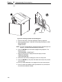
6 Reprogramming the Security Key....................... 127
Reprogramming The Security Key........................................................127
How To Program The Security Key................................................127
7 Troubleshooting.................................................. 129
Cleaning Requirements ........................................................................129
Exterior Cleaning............................................................................129
Interior Cleaning .............................................................................130
Diagnosing Problems............................................................................132
Bar Code Verification .....................................................................132
Printing A Hex Dump......................................................................132
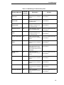
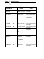
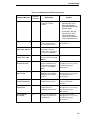
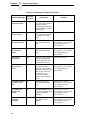
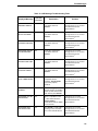
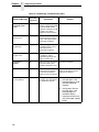
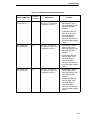
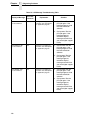
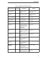
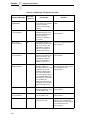
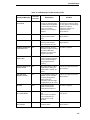
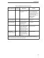
Fault Messages ..............................................................................133
A Printer Specifications ......................................... 169
Ribbon Cartridge Specifications ...........................................................169
Paper Specifications .............................................................................169
Labels ...................................................................................................170
Printer Weight And Dimensions............................................................170
Environmental Characteristics ..............................................................170
Acoustic Noise Level ............................................................................171
Energy Star...........................................................................................171
Table of Contents
Electrical Characteristics ...................................................................... 171
Input Voltage .................................................................................. 171
Power Consumption ....................................................................... 172
Interfaces .............................................................................................. 172
Printing Rates .......................................................................................173
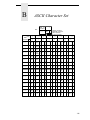
B ASCII Character Set ........................................... 175
C Zero Tear Pedestal ............................................ 177
Overview............................................................................................... 177
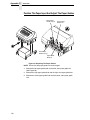
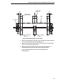
Position The Paper Input And Adjust The Paper Guides ............... 178
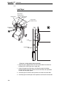
Load Paper..................................................................................... 180
Position The Paper Out Sensor ..................................................... 182
Set The Tear Bar Distance.............................................................183
Set The Top Of Form ..................................................................... 184
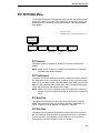
ZTP SETTINGS Menu ..........................................................................185
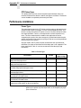
Performance Limitations ....................................................................... 186
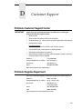
D Customer Support .............................................. 189
Printronix Customer Support Center..................................................... 189
Printronix Supplies Department ............................................................ 189
Corporate Offices.................................................................................. 190
E Communication Notices ..................................... 191
Notices.................................................................................................. 191
Energy Star........................................................................................... 193
Communication Statements.................................................................. 193
Software License Agreement................................................................ 198
1
Introduction
Printer Overview
This chapter provides a general overview of your printer and the conventions
used within this manual.
Printronix P7000 H-Series Printers
Printronix® has been the global leader in industrial printing solutions for over
30 years, earning a reputation for designing and manufacturing leading edge
products and delivering them to market with unsurpassed service and
support.
The Printronix P7000™ Line Matrix Printing Platform extends the series of
technology innovations that cement Printronix’s leadership position. Line
matrix printing is Printronix’s flagship technology, and it remains the
workhorse solution for supply-chain and back-office printing applications
because of its reliability, lower cost of ownership and flexibility of printing
applications.
•
Most reliable printer ever – provides more up time and lower operating
costs
•
Ultra capacity ribbons – deliver darker image, last longer, and costs less
to operate than other print technologies
•
Integrated print management system – provides precise control over print
quality, print costs, and job planning
•
Cabinet or Pedestal styles – best user access and forms handling
flexibility
•
Unsurpassed ease of use – simplifies operation and enhances
productivity
9
Chapter
1
Printer Overview
There are three printer configurations:
Enclosed Cabinet (P72XXH)
•
The enclosed cabinet models provide for near silent operation, making
these printers perfectly suitable for use in the quietest of office
environments.
•
Provides the best paper handling for large print runs. All paper input and
output is contained inside the cabinet and protected from bumping and
contamination.
•
Highly effective combination of moveable fences and chains allows for
precise stacking all the way up to a full box of paper.
•
For tougher forms that tend not to refold well, a SureStak power stacker
option is available for the enclosed cabinet models.
•
Available in four print speeds – 200 line per minute, 300 line per minute,
600 line per minute, and 800 line per minute models.
Pedestal (P70XXH)
•
The pedestal model has a clamshell design that allows easy access to all
controls providing faster ribbon replacements and easier paper loading
•
•
•
Oversized casters are standard making movement easy.
•
Available in four print speeds – 200 line per minute, 300 line per minute,
600 line per minute, and 800 line per minute models.
Versatility to configure the paper path for either top or rear exit.
Using the top paper exit, this printer is ideal for short print runs and easy
access to output
Zero Tear Pedestal (P70XXZTH)
10
•
Special push tractor configuration enables printing from the very first to
the very last line of a form and then tear-off with no forms lost
•
The elimination of wasted forms between jobs can yield significant
savings.
•
•
An ideal solution for supply-chain and back-office applications.
Available in three print speeds – 200 line per minute, 300 line per minute,
and 600 line per minute models.
Printronix P7000 H-Series Printers
Conventions In This Manual
All uppercase print indicates control panel keys.
Example: Press the CLEAR key, then press the ON LINE key.
Quotation marks (“ ”) indicate messages on the Liquid Crystal Display (LCD).
Example: Press the ON LINE key. “OFFLINE” appears on the LCD.
The + (plus) symbol represents key combinations.
Example: “Press = + >” means press the = (UP) key and the
> (DOWN) key at the same time.
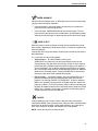
Warnings And Special Information
Read and comply with all information highlighted under special headings:
WARNING
A warning notice calls attention to a condition that could harm you.
WARNUNG
Ein Warhinweis dieser Art weist auf Verletzungsgefahr hin.
AVISO
Las notas de adviso llaman la atención sobre una condición que puede
causar lesiones.
ATTENTION
Attire votre attention sur une opération pouvant présenter un danger.
AVVERTENZA
Un’indicazione di avvertenza segnala una condizione di pericolo
suscttibile causare lesioni all’operatore.
CAUTION
A caution notice calls attention to a condition that could damage the
printer.
11
Chapter
1
Related Documents
Related Documents
•
Quick Reference Guide — Explains how to set up the printer for basic
operation (load ribbon cartridge and media, and clear paper jams).
•
Maintenance Manual — Explains how to maintain and repair the line
matrix printer at the field service level of maintenance.
•
Network Interface Card User's Manual — Information about network
protocols, configuration, and operation.
•
LQ-1600K Emulation For The P7000 H-Series Of Line Matrix Printers
Programmer’s Reference Manual — Covers the host control codes for the
LQ-1600K emulation.
•
KS Programmer’s Reference Manual — Covers the host control codes for
the KS emulation.
•
KSSM Programmer’s Reference Manual — Covers the host control codes
for the KSSM emulation.
Taking Care Of Your Printer
Your printer will produce high print quality jobs if it is well taken care of.
Periodic cleaning, handling the printer properly, and using the correct printer
supplies such as paper and ribbons ensures optimum performance.
Chapter 7 explains how to clean the printer, and printer supplies are listed in
Appendix A.
Protocols And Emulations
A protocol is a set of rules governing the exchange of information between the
printer and its host computer. These rules consist of codes that manipulate
and print data and allow for machine-to-machine communication. A printer
and its host computer must use the same protocol. As used in this manual,
protocol and emulation mean the same thing.
Most impact printers use single ASCII character codes to print text, numbers,
and punctuation marks. Some characters, are defined as control codes.
Control codes instruct the printer to perform specific functions, such as
underlining text, printing subscripts, setting page margins, etc. The main
difference between most printer protocols is in the characters used to create
control codes and the ways in which these characters are formatted.
When the printer executes the character and control codes of a particular
printer protocol, it is “emulating” that printer.
12
2
Setting Up The Printer
Before You Begin
Read this chapter carefully before installing and operating the printer. The
printer is easy to install. However, for your safety and to protect valuable
equipment, perform all the procedures in this chapter in the order presented.
Power Requirements
The printer must be connected to a power outlet that supplies 88 to 270 volts
AC. The printer automatically senses and adjusts itself to conform to the
correct voltage range.
Primary circuit protection is provided by the power switch, which is also a
circuit breaker. Consult an electrician if printer operation affects local
electrical lines. See “Electrical Characteristics” on page 171 for additional
power specifications.
IMPORTANT
Printer power should be supplied from a separate AC circuit protected
at 10 amperes for 100 - 120 volts or 5 amperes for 200 - 240 volts at 50 or
60 Hertz.
Select A Site
Select a printer site that meets all of the following requirements:
•
•
Permits complete opening of the printer cover and doors.
•
Has a standard power outlet that supplies 88-135 Volts AC or
178-270 Volts AC power, at 47 to 63 Hz.
•
•
Is relatively dust-free.
•
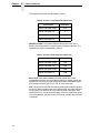
Is located within the maximum allowable cable length to the host
computer. This distance depends on the type of interface you plan to use,
as shown in Table 1 on page 14.
For cabinet models, allows at least three feet of clearance behind the
printer. (This permits air to circulate freely around the printer and provides
access to the paper stacking area.)
Has a temperature range of 10° C to 40° C (50° F to 104° F) and a
relative humidity from 15% to 90% non-condensing.
13
Chapter
2
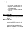
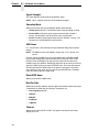
Printer Dimensions
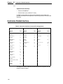
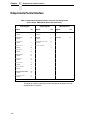
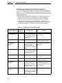
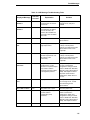
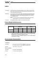
Table 1. Maximum Interface Connection Cable Length
Interface Type
Maximum Cable Length
Centronics Parallel
5 meters (15 feet)
Dataproducts Parallel
12 meters (40 feet)
IEEE 1284 Parallel
10 meters (32 feet)
Serial RS-232
15 meters (50 feet)
Serial RS-422
1220 meters (4000 feet)
Dataproducts Long Line
150 meters (492 feet)
Coax
1500 meters (4920 feet)
Twinax
1500 meters (4920 feet)
Twinax (shielded cable)
1500 meters (4920 feet)
Twisted Pair / Type 3
300 meters (985 feet)
Ethernet 10/100Base-T
100 meters (328 feet)
183468b
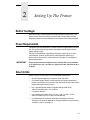
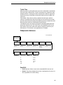
Printer Dimensions
41.0 in
57.5 in
(104 cm) (146.1 cm)
27.0 in
(68.84 cm)
29.0 in
(73.7 cm)
83.0 in
(210.8 cm)
27.0 in
(68.6 cm)
27.0 in
(68.6 cm)
Figure 1. Printer Dimensions - Cabinet Model
14
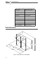
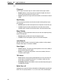
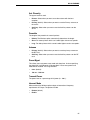
183469b
59.0 in
(149.9 cm)
42.5 in
(107.8 cm)
27.0 in
(68.6 cm)
83.0 in
(210.8 cm)
32.5 in
(82.6 cm)
27.0 in
(68.6 cm)
27.0 in
(68.6 cm)
32.0 in
(81.3 cm)
Figure 2. Printer Dimensions - Cabinet Model with Paper Stacker
15
Chapter
2
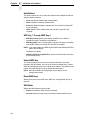
Printer Dimensions
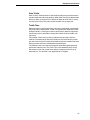
25 in.
(63.5 cm)
TO
F
TO
F
10.5 in.
(26.67 cm.)
TO
F
TO
F
48.0 in.
(122 cm)
183882a
24.6 in.
(62.48 cm)
30 in.
(76.2 cm.)
183882 REV A
Figure 3. Printer Dimensions - Pedestal Model
16
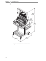
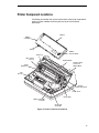
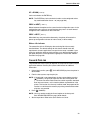
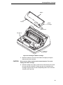
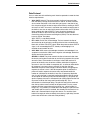
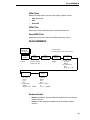
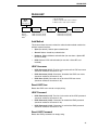
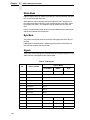
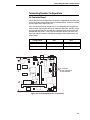
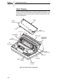
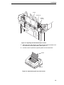
Printer Component Locations
Familiarize yourself with the names and locations of the printer components,
shown in Figure 4 before continuing with the rest of the installation
procedures.
Ribbon
Ribbon
Cartridge
Tab (2)
Ribbon
Tension Knob
Tractor (2)
Blue Tractor
Lock (2)
Splined Shaft
Hammer Bank
Cover and
Ribbon Mask
Paper
Support (2)
TO
F
TO
F
Tab
Slot (2)
TO
F
TO
F
183871a
Vertical
Position Knob
Platen Lever
Platen Stop
Ribbon Cartridge
Interface
Air Shroud
Assembly
183871 REV A
Figure 4. Printer Component Locations
17
Chapter
18
2
Printer Component Locations
3
Operating The Printer
Powering On The Printer
When you power on the printer, it executes a self-test. The default power-up
state is online. When the self-test completes and the software has initialized
successfully, the status indicator light turns on, indicating the printer is online.
The default value of the type of emulation you have installed appears in the
upper right corner of the display. The ribbon life remaining is shown on the
second line.
If there is a fault during the self-test, the status indicator flashes and a specific
fault message appears on the display (such as “LOAD PAPER”). The alarm
also sounds if it is configured to do so. See “ LCD Message Troubleshooting
Table” on page 134 for information on fault messages and solutions.
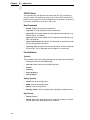
Operating Modes
Online. In online mode, the printer can receive and print data sent from the
host. Pressing the
(ON LINE/CLEAR) key toggles the printer from online
to offline mode. The status indicator is lit in online mode.
Offline. In offline mode, you can perform operator functions, such as loading
paper and setting top-of-form. You can also move within the printer
(ON LINE/CLEAR) key toggles the
configuration menus. Pressing the
printer from offline to online mode. The status indicator is off in offline mode.
Fault. In fault mode, a condition exists which must be cleared before printing
can continue. The status indicator flashes, the alarm beeps (if configured to
sound), and a descriptive fault message displays.
The current operating mode can be selected via control panel keys or can
result from routine operations such as powering on the printer.
19
Chapter
3
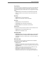
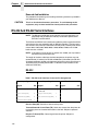
The Control Panel
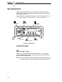
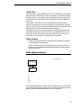
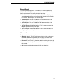
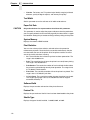
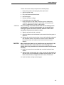
The Control Panel
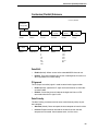
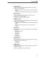
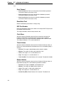
Figure 5 shows the keys, displays, and indicators as they appear on the
control panel. The following section provides the descriptions, and functions
of the control panel keys.
Key combinations are indicated with the plus (+) sign. For example, “Press U
+ V” means to press the U key and the V key at the same time.
PRT CONFIG
SET TOF
JOB SELECT/
PRINT MODE
183452b
ENTER
CANCEL
ON LINE/CLEAR
VIEW/EJECT
PAPER ADVANCE
Figure 5. Control Panel
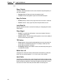
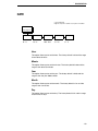
Control Panel Keys
ON LINE / CLEAR
Toggles the printer between online and offline modes. If a fault condition
exists, pressing this key will clear the fault message and return the printer
from fault mode to offline mode.
NOTE: If the fault condition is not corrected before pressing this key, the fault
message will reappear when attempting to place the printer online.
20
Control Panel Keys
PAPER ADVANCE
Performs advance to top-of-form, as defined by the current active form length.
The key works both online and offline.
•
If online with data in the printer buffer, the data will print and then the
paper will move to the next top-of-form.
•
In the fault state, PAPER ADVANCE will advance the paper. The first
press moves to the top of the next available form. All subsequent presses
advances one forms length as defined by the current active forms length.
VIEW / EJECT
When the printer is online or offline, pressing this key executes the view or
eject function, depending on whether the printer is a cabinet or a pedestal (or
zero tear pedestal).
If online with data in the printer buffer, the data prints and the key functions as
described below.
If in a fault state, this key will be ignored.
•
View Function — for cabinet models, pressing the
VIEW/EJECT key moves the last data printed to the tractor area for
viewing. While in the view state, the message "Printer in View" displays,
pressing the UP or DOWN arrow keys moves the paper up or down in 1/
72 inch increments. This is done to align the image within a pre-printed
form, for example. Refer to the UP and DOWN key functions for additional
details on the microstep feature. Pressing VIEW/EJECT a second time
moves the paper back to the adjusted print position.
•
Eject Function — for pedestal models, when the VIEW/EJECT key is
pressed, the bottom of the last printed form will move to the tear bar
position. The message "READY TO TEAR/EJECT To Return" displays.
While in this position, pressing the UP or DOWN arrow keys moves the
paper up or down in 1/72 inch increments. Refer to the Up and Down key
functions for additional details on the microstep feature. When the VIEW/
EJECT key is pressed a second time, the printer will move the paper to
enable printing on the next available form.
CANCEL
In offline mode, this key cancels all data in the print buffer, if enabled in
“ADVANCED USER” menu (see page 104). The print buffer is cleared without
printing any of the data and the current paper position is set as the top-ofform. If this function is disabled, the CANCEL key will be ignored.
NOTE: Use of this key will cause loss of data.
21
Chapter
3
The Control Panel
SET TOF
Sets the top-of-form on the printer. This key is active only when the printer is
offline and will not operate if the printer is in a fault condition. The paper
moves down to the print position and aligns to the top-of-form. See the Quick
Setup Guide for the complete top-of-form setting procedure.
NOTE: If there is any data in the buffer, the paper will move to the last print
position.
PRT CONFIG
In offline mode, PRT CONFIG prints the current printer configuration. This key
requires a confirmation with the ENTER key; pressing any other key will exit
from this function. See “The Configuration Menus” on page 41 for an
explanation of configuration menus.
JOB SELECT/PRINT MODE
In offline mode, this key allows for fast selection of any of the previously
stored configurations or typeface of the printer. Pressing this key causes the
printer to cycle through the following messages: Load Config., Factory Config,
Load Config 1, Load Config 2, Load Config 3,...,Load Config 8.
ENTER
When navigating the configuration menus, ENTER selects the currently
displayed option value as the active value. An asterisk (*) appears next to the
active value on the display. ENTER is also used for starting and stopping
printer tests and generating a configuration printout.
NOTE: The ENTER key must be unlocked in order to function.
See UP + DOWN, below.
The ENTER key lock and unlock function can be configured to be a
key combination other than = + > (see page 108).
UP or DOWN ( = or > )
Moves up or down between levels in the configuration menus and makes
vertical forms adjustment. After pressing VIEW, press = or > to adjust the
paper up or down in 1/72 inch increments for fine vertical forms alignment.
When the printer is in offline mode, press = or > to move through levels in the
configuration menus.
22
Cancel A Print Job
UP + DOWN ( = + > )
Locks and unlocks the ENTER key.
NOTE: The ENTER key lock and unlock function can be configured to be a
key combination other than = + > (see page 108).
PREV or NEXT ( ; or < )
Moves between the options on the current level of configuration menu. In the
configuration menu, press ; to scroll backward or press < to scroll forward
through the menu selections on the same level.
PREV + NEXT ( ; + < )
When both keys are pressed simultaneously, the printer will reset to the
power-up configuration and reset its internal state (in offline mode).
Ribbon Life Indicator
The second line of the LCD displays the remaining life of the currently
installed ribbon. The default settings for this feature should match the
requirements for most applications; no special user setup is needed. If your
particular application requires darker printing or can tolerate lighter printing,
the ribbon end point can be adjusted as appropriate. Please refer “Ribbon
End Point” on page 102.
Cancel A Print Job
The procedure to cancel a print job depends on the printer emulation and your
application software. Contact your system administrator for additional
information.
1. If the printer is online, press
offline mode.
(ON LINE/CLEAR) to place the printer in
2. From the host system, stop the print job.
NOTE: If the print job is not stopped from the host system before pressing
(CANCEL), the print job continues with data missing when the
printer returns to online mode. Exercise caution to prevent unwanted
data loss occurrences, as this function deletes unprinted data in the
printer. This function is active only in offline mode; the purpose of this
function is to eliminate the necessity of printing unwanted data when
print jobs are canceled.
3. Press
(CANCEL).
NOTE: You may need to enable the Cancel option on the front panel.
See “ADVANCED USER” on page 104 for details.
4. Set the top-of-form. Refer to the Quick Reference Guide.
23
Chapter
3
Operational Procedures
Operational Procedures
This section contains routine printer operating procedures on how to:
•
•
•
reload paper;
unload paper;
cancel a print job.
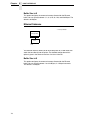
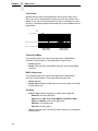
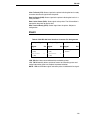
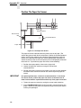
Reload Paper
Do this procedure when “LOAD PAPER” displays. (This message occurs
when the last sheet of paper passes through the paper slot.) This procedure
reloads paper without removing the last sheet of the old paper supply, while
retaining the current top-of-form setting.
Wire
Guide (2)
Paper Slot
Paper
Slot
183440b
Metal Paper Guide
(P7208H)
183439b
Cabinet Model
Pedestal Model
Figure 6. Paper Slot Location
1. Raise the printer cover. Raise the platen lever as far as it will go. (See
“Printer Component Locations” on page 17 for the location of the lever.)
2. Press
(ON LINE/CLEAR) to turn off the alarm. Do not open the tractor
doors or remove the existing paper.
3. For cabinet models, open the front door. Align the paper supply with the
label on the floor. Ensure the paper pulls freely from the box.
4. Feed the paper up through the paper slot (see Figure 6). It may be easier
to feed one corner of the new paper up through the slot first. When this
corner can be grasped from the top, rotate the paper back to the normal
position.
NOTE: If you are using thick, multi-part forms and are unable to load the new
paper over the existing paper, go to step 15.
5. Hold the paper to prevent it from slipping down and through the paper
slot.
24
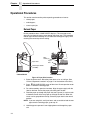
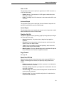
Reload Paper
New Paper
Existing Paper
183888a
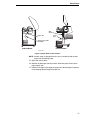
Figure 7. Loading New Paper into the Printer
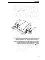
6. Pull the new paper above and behind the ribbon mask, but in front of the
existing paper. The ribbon mask location is shown on the ribbon path
diagram. If necessary, gently press the existing paper back.
7. Align the top edge of the new paper with the top perforation of the existing
paper.
8. Load the new paper over the existing paper. Open and load the tractors
one at a time to prevent the paper from slipping.
NOTE: Make sure that the top edge of the new paper lines up with the top
horizontal perforation of the last page.
25
Chapter
3
Operational Procedures
Vertical Position
Knob
A
183445b
Paper Thickness
Indicator
A
183444b
183446b
Platen
Stop
Platen Lever
Platen Stop
Knob
Figure 8. Setting the Platen Lever
9. Turn the platen stop knob clockwise or counterclockwise to match the
paper thickness. (The A-B-C scale corresponds approximately to 1-, 3-,
and 6-part paper thickness).
NOTE: If you are using the same thickness of paper, there is no need to
readjust.
10. Lower the platen lever.
NOTE: Do not set the platen lever too tightly; excessive friction can cause
paper jams, ribbon jams with potential for ribbon damage, smeared
ink, or wavy print.
11. Press
(ON LINE/CLEAR) to remove the “LOAD PAPER” fault
message from the display.
12. Press
(PAPER ADVANCE) several times to make sure the paper
feeds properly beyond the tractors and over the lower paper guide. Feed
sufficient paper to ensure the paper stacks correctly.
13. Close the printer cover. Close the cabinet front door.
14. Press
(ON LINE/CLEAR) to place the printer in online mode and
resume printing.
26
Reload Paper
Wire
Guide (2)
Paper Slot
Paper
Slot
183440b
Metal Paper Guide
(P7208H)
183439b
Cabinet Model
Pedestal Model
183439 REV B
183440 REV B
Figure 9. Paper Slots on the Printers
NOTE: Perform steps 15 through 32 only if you are unable to load the new
paper over the existing paper.
15. Open both tractor doors.
16. Remove the old paper from the tractors. Allow the paper to fall into the
paper supply area.
17. Feed the new paper up through the paper slot. Hold the paper to prevent
it from slipping down through the paper slot.
27
Chapter
3
Operational Procedures
Left Tractor Door
Paper
Left Tractor Lock
TO
F
TO
F
183441b
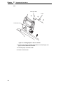
Figure 10. Loading Paper on the Left Tractor
18. Pull the paper above and behind the ribbon mask. See Figure 4 on
page 17 for the ribbon mask location.
19. Load the paper on the left tractor.
20. Close the tractor door.
28
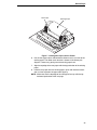
Reload Paper
Tractor
Paper
Tractor
Splined Shaft
183442b
Tractor Lock
Paper Scale
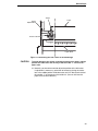
Figure 11. Positioning the Left Tractor to Avoid Damage
CAUTION
To avoid damage to the printer caused by printing on the platen, always
position the left tractor unit directly to the left of the “1” mark on the
paper scale.
21. Normally, you should not need to adjust the position of the left tractor.
If adjustment is necessary, unlock the left tractor by placing the tractor
lock in the middle position. Slide the tractor until it is directly to the left of
the number “1” on the paper scale and lock it. (You can also use the
paper scale to count columns.)
29
Chapter
3
Operational Procedures
Tractor Door
TO
F
TO
F
TO
F
TO
F
183443b
Tractor Lock
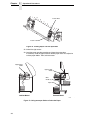
Figure 12. Loading Paper onto the Sprockets
22. Unlock the right tractor.
23. Load the paper onto the sprockets and close the tractor door.
If necessary, slide the right tractor to remove paper slack or to adjust for
various paper widths. Then, lock the tractor.
Upper Paper
Guide
Upper Paper
Guide
Wire
Guide (2)
Paper Slot
183440b
183439b
Cabinet Model
Pedestal Model
183439 REV B
Figure 13. Using the Paper Guide to Orient the Paper
30
183440 REV
Reload Paper
24. Pedestal models:
Using the vertical position knob to move the paper up, guide the paper
over the lower paper guide and through the slot in the top cover. For
pedestal models with the Quick Access Cover, refer to the Quick Setup
Guide for paper exiting options.
25. Press
(PAPER ADVANCE) several times to make sure the paper
feeds properly beyond the tractors and over the lower paper guide. Feed
sufficient paper to ensure the paper stacks correctly.
26. Cabinet models:
Open the cabinet rear door. Make sure the paper is aligned with the label
in the output area (inside the cabinet). Close the front and rear doors.
TOF Indicator
Perforation
TO
F
TO
F
Vertical
Position
Knob
TO
F
TO
F
183967a
Figure 14. Aligning the Perforation with the TOF Indicator
27. Align the top of the first print line with the TOF indicator on the tractor by
rotating the vertical position knob. For best print quality, set the top-ofform at least 1/2 inch below the perforation.
NOTE: For exact positioning, press the
(VIEW/EJECT) key to move the
last data printed to the tractor area for viewing. While in View mode
“Printer in View” displays. Press the Up or Down Arrow keys to move
the paper vertically in small increments. Pressing the
(VIEW/
EJECT) key a second time moves the paper back to the adjusted
print position. The key owrks both online and offline provided that the
printer is in View mode. (This procedure is applicable for both the
cabinet and pedestal models.)
31
Chapter
3
Operational Procedures
Vertical Position
Knob
Paper Thickness
Indicator
A
183445b
A
183444b
183446b
Platen
Stop
Platen Lever
Platen Stop
Knob
183444 REV B
Figure 15. Adjusting the Platen Lever
28. Turn the platen stop knob clockwise or counterclockwise to match the
paper thickness. (The A-B-C scale corresponds approximately to 1-, 3-,
and 6-part paper thickness. Adjust until you have the desired print
quality.)
NOTE: The platen stop allows you to set an optimum and consistent
thickness that is not affected when opening and closing the platen
lever.
29. Lower the platen lever until it stops.
30. Press
(ON LINE/CLEAR) to clear any fault messages (such as “LOAD
PAPER”) from the LCD.
31. Press
(SET TOF). The top-of-form you have set moves down to the
print position. If there is data in the buffer, the paper moves forward to the
last print position on the next page.
32. Press
32
(ON LINE/CLEAR) and close the printer cover.
Unload Paper
Unload Paper
1. Press
(ON LINE/CLEAR) to place the printer in offline mode and open
the printer cover.
2. For cabinet models, open the cabinet rear door. For models with the
power stacker installed, press the STACKER UP key on the rear control
panel.
Paper
Perforation
TO
F
TO
F
TO
F
TO
F
183477b
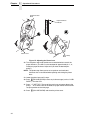
Figure 16. Unloading the Paper from the Printer
3. Tear off the paper at the perforation.
4. Allow the paper to fall to the back of the printer and into the paper
stacking area.
5. For pedestal models, remove the stacked paper from the paper tray.
33
Chapter
3
Operational Procedures
183478b
Paper
Power Stacker
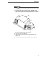
Figure 17. Removing Stacked Paper from the Printer
6. For cabinet models, remove the stacked paper from the rear cabinet floor.
For cabinet models with the power stacker installed, remove the paper
from the wire paper tent and press the STACKER DOWN key to lower the
stacker mechanism.
7. Close the cabinet rear door.
34
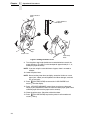
Unload Paper
Tractor Door
183904a
Platen Lever
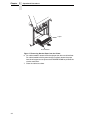
Figure 18. Completely Removing the Paper
8. To completely remove the paper from the printer:
a. Raise the platen lever as far as it will go and open both tractor doors.
CAUTION
Be careful when pulling any paper backward through the paper path,
especially when using a label stock. If you are not careful, labels can
detach and adhere to the printer within the paper path, where only an
authorized service representative can remove them.
b. Open the cabinet front door.
c.
Gently pull the paper down through the paper slot. Allow the paper to
fall into the paper supply area.
d. Remove the paper from the paper supply area.
35
Chapter
3
Integrated Print Management System
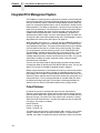
Integrated Print Management System
The P7000 has a new feature that automatically monitors and communicates
the status of the ribbon life to help the operator know when to change ribbons.
Using an ink delivery system called the Cartridge Ribbon System (CRS), the
printer can automatically detect when a new or used ribbon is loaded, and all
ribbon properties. The ribbon is contained in a plastic box (the cartridge) and
feeds only in one direction. The CRS contains an interface board that allows
communication between the printer and the cartridge. Using the CRS, the
P7000 automatically detects when a new or used ribbon is installed and
determines the ribbon’s length, ink color, and expected yield. The ribbon life,
starting from 100% when new and decreasing to 0% when depleted, is always
displayed on the control panel. See Figure 5 on page 20.
When the ribbon life reaches 2%, a warning message “RIBBON UNDER 2%/
Change RBN soon” appears on the control panel display. The control panel
status indicator lamp flashes. The printer will continue printing in this condition
until the ribbon life reaches 0% at which time, printing will stop. The ribbon
may be changed at any time while the printer is in the “RBN END POINT/
Change Ribbon” condition without losing data in the printer’s buffer. If a new
ribbon is loaded, the system automatically detects the change, clears the
condition when the platen is closed, and restarts the life at 100%. If a partially
used ribbon is loaded, the system continues the life at the percentage
indicated for the used ribbon.
You may also resume printing for approximately two more minutes without
changing the ribbon by pressing the ON LINE/CLEAR key twice. This may be
done as many times as needed to complete the job in progress.
Ribbon usage information is calculated by maintaining a count of impressions
(dots) that is stored on the ribbon cartridge and updated periodically so that
the cartridge can be used on a different printer with the information intact. This
allows the system administrator to have precise control over print quality and
consumable costs. The accurate presentation of available ribbon life allows
for efficient planning of print jobs. For example, if the displayed ribbon life
were low, you can install a new ribbon before printing a large print job.
Output Darkness
By default the system is configured to meet most user requirements.
However, some applications require that the output remains darker than the
nominal set point while some applications are less critical and could tolerate a
lighter final image. The system can easily adjust to this variability. A setting
under the Printer Control menu is available that allows the user to adjust the
final output. The range is as follows:
Normal (Default)
Darker +1 through +6
Lighter -1 through -10
The ribbon life indicator always cycles between 100% and 0%, but if a darker
setting is selected, zero will be reached more quickly. If a lighter setting is
selected, the system will extend the amount of printing it takes to reach zero.
36
Loading a Used Ribbon Cartridge
Loading a Used Ribbon Cartridge
You can take the ribbon cartridge off the printer and reload it at a later time.
The ribbon life gauge automatically updates to reflect the correct remaining
capacity.
NOTE: Since the ribbon usage information is stored on the ribbon cartridge,
you can reload a partially used cartridge onto a different printer.
Lighter Or Darker Print
The ribbon life value as determined by the Integrated Print Management
System is factory set so that the image quality at the end of the ribbon life is
as good as it was when the ribbon was new. You may adjust the ribbon end
point for a lighter or darker image as required for your printing needs.
See “PRINTER CONTROL” on page 102.
37
Chapter
3
Integrated Print Management System
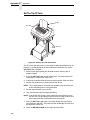
Changing Ribbon Cartridge
Before changing the ribbon cartridge, determine whether at the end of ribbon
life if you want to make the print lighter (extend the ribbon life) or darker
(shorten the ribbon life). If you want to make the print lighter, go to “Ribbon
End Point” on page 57 and follow the procedures for adjusting the image
density. If you are satisfied with the print darkness, or if you want to increase
the darkness at the end of ribbon life, continue with the following steps.
NOTE: Ribbon cartridge instructions and illustrations shown in the following
section are for the pedestal model. Follow the same procedures for
the cabinet model.
TO
F
TO
F
Blue Tractor
Door (2)
183816a
Platen Lever
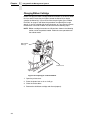
Figure 19. Preparing to Load the Ribbon
1. Open the printer cover.
2. Raise the platen lever as far as it will go.
3. Close the tractor doors.
4. Remove the old ribbon cartridge and discard properly.
38
Changing Ribbon Cartridge
Ribbon
Tab (2)
Ribbon
Cartridge
Ribbon
Tension Knob
Tab Slot (2)
TO
F
TO
F
TO
F
TO
F
183871a
Air Shroud
Assembly
Figure 20. Installing the Ribbon Cartridge
5. Remove the ribbon slack on the new ribbon cartridge by turning the
ribbon tension knob clockwise.
CAUTION
Do not turn the ribbon tension knob counterclockwise. This could
damage the ribbon cartridge.
6. Hold the cartridge at an angle, so that the rear side nearest you is lower
than the side with the ribbon. Find the two tabs on the outside of the
cartridge and place them into the corresponding slots on the air shroud
assembly (see Figure 20).
39
Chapter
3
Integrated Print Management System
Ribbon
Cartridge
A
TOF
TO
F
TO
Ribbon Mask
F
TO
F
183874a
Hammerbank
Cover
Ribbon
TO
F
A
TO
F
183872a
Ribbon Tension Knob
Ribbon Cartridge
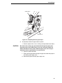
Figure 21. The Ribbon Cartridge Snapped in Place
7. Rock the cartridge downward, making sure that the ribbon goes between
the guide and the mask (see Figure 21). You will feel it snap into place.
CAUTION
Make sure that the ribbon does not twist or fold over.
8. Turn the ribbon tension knob clockwise a few times to make sure the
ribbon tracks correctly in the ribbon path.
9. Close the platen lever.
10. Close the printer top cover.
If you want to increase the darkness level of the ribbon at the end of life, go to
“Ribbon End Point” on page 57 and follow the procedures for adjusting the
image density.
If you are satisfied with the print darkness, press the
key twice to return the printer to operation.
40
(ON LINE/CLEAR)
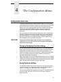
4
The Configuration Menus
Configuration Overview
To print data, the printer must respond correctly to signals and commands
received from the host computer. Configuration is the process of matching the
printer's operating characteristics to those of the host computer and to
specific tasks, such as printing labels or printing on different sizes of paper.
The characteristics which define the printer's response to signals and
commands received from the host computer are called configuration
parameters.
You can configure the printer using the configuration menus and the control
panel or by sending control codes in the data stream from a host computer
attached to the printer. This chapter provides an introduction to configuring
the printer and includes the configuration menus available (depending on
which emulation you have installed in the printer).
IMPORTANT
Configuration directly affects printer operation. Do not change the
configuration of your printer until you are thoroughly familiar with the
procedures in this chapter.
Changing And Saving Parameter Settings
You may change a printer parameter setting, such as line spacing or forms
length, either by pressing keys on the control panel or by sending emulation
control codes in the data stream from a host attached to the printer. The
control panel allows you to configure the printer’s resident set of configuration
menus. An example procedure for using the control panel to change
parameter settings begins on page 43.
When control codes are sent from a host attached to the printer, they override
control panel settings. For example, if you set the line spacing to 6 lpi with the
control panel, and application software later changes this to 8 lpi with a control
code, the control code overrides the control panel setting.
Saving Parameter Settings
The parameter settings that you have changed can be permanently stored in
the printer’s memory as a configuration. See “Auto Save Configuration” on
page 46. and “Saving Your New Configuration” on page 46.
You may also save your new configurations using the PTX_SETUP command
host control code. See your LinePrinter Plus Programmer’s Reference
Manual for details.
41
Chapter
4
Configuration Overview
Default And Custom Configurations
A configuration consists of a group of parameter settings, such as line
spacing, forms length, etc. Your printer provides a fixed default configuration
and allows you to define several custom configurations for use with particular
print jobs. The factory default configuration can be loaded, but it cannot be
altered.
Eight configurations can be modified for unique print job requirements. The
“Save Config.” option allows you to save eight groups of parameter settings in
memory as custom configurations numbered from 1 through 8. An
explanation on how to save a set of parameter values as a custom
configuration using the “Save Config.” menu option begins on page 46.
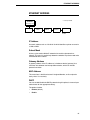
Navigating The Menus
To manipulate configurations review the following instructions about
navigating through the menus.
You must be offline to move within the menus.
ON LINE/CLEAR
Press to toggle between ONLINE and OFFLINE.
Menus are accessed with the printer offline.
Press to move up or down through the menu levels.
OR
Press to scroll through the available choices on a
chosen level.
OR
ENTER
+
Press to confirm selection.
Press to lock and unlock the ENTER key. The
ENTER key is locked by default to prevent you
from accidentally changing the printer
configuration. The lock and unlock function can be
configured to be other than = + > (See “Set Lock
Key” on page 108.)
To experiment with navigating the menus, use the example on the next page
as a tutorial.
42
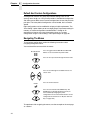
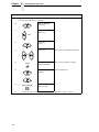
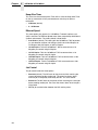
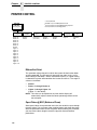
Changing Parameters Example
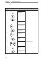
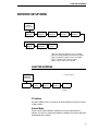
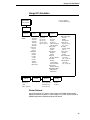
Changing Parameters Example
* = Factory Default
OFFLINE
1
QUICK
SETUP
...
Only for P7000 Pedestal Model
PRINTER
CONTROL
Ribbon End
Point
Darker +6
Darker +5
Darker +4
Darker +3
Darker +2
Darker +1
Normal
Lighter -1
Lighter -2
Lighter -3
Lighter -4
Lighter -5
Lighter -6
Lighter -7*
Lighter -8
Lighter -9
Lighter -10
Open Platen
@ BOF
Disable*
Enable
Unidirectional
Disable*
Enable
Tear Bar
Dist.
7.46 in.*
(4.5-10.5 in.)
Display
Language
English*
View
Function 1.
Disable*
Enable
Accented
Char
Standard*
Tall
A configuration consists of several parameters. The default factory
configuration has a starting set of parameters. In the configuration menu
above, and in all the configuration menus in this chapter, the factory default
values are indicated by an asterisk (*).
Your print jobs may require parameter values which vary from the default
settings. This section provides an example procedure for changing individual
parameter values.
The following procedure shows how to change and save the settings for the
Unidirectional and Accented Char options. Use these guidelines to navigate
the configuration menus and change other parameters.
NOTE: When changing Ribbon End Point parameters, all changes will apply
to every configuration saved. Changes to Ribbon End Point cannot
be saved to an individual configuration.
43
Chapter
4
Configuration Overview
Step
Press
1.
Make sure the printer is on.
2.
ON LINE/CLEAR
3.
LCD
Notes
OFFLINE
QUICK SETUP
ENTER SWITCH
UNLOCKED
Allows you to make configuration changes.
+
OFFLINE
QUICK SETUP
4.
OFFLINE
PRINTER CONTROL
UNTIL
5.
PRINTER CONTROL
Ribbon End Point
6.
PRINTER CONTROL
Unidirectional
UNTIL
7.
Unidirectional
Disable*
8.
Unidirectional
Enable
Cycle through the choices.
Unidirectional
Enable*
The * indicates this choice is active.
OR
9.
10.
44
ENTER
PRINTER CONTROL
Unidirectional
Changing Parameters Example
Step
Press
11.
LCD
Notes
PRINTER CONTROL
Accented Char
UNTIL
12.
Accented Char
Standard*
13.
Accented Char
Tall
Press until the desired parameter displays.
Accented Char
Tall*
The * indicates this choice is active.
ENTER SWITCH
LOCKED
Locks the ENTER key.
ENTER = Save
ONLINE = No Save
Press ENTER to automatically save
configuration changes. Press ONLINE to
continue without saving.
Cfg = 1*
= Power-Up Cfg
Configuration changes have been saved as
Configuration 1, and will be set as the
Power-Up config. The printer will then be
brought online.
ONLINE
Ribbon Life 100%
Places the printer online without
permanently saving the configuration
changes.
OR
14.
ENTER
15.
+
16.
ON LINE/CLEAR
17A.
ENTER
17B.
ON LINE/CLEAR
18.
The printer is ready for operation
The parameters you have changed will remain active as long as the printer is
on. When you turn off the printer, the parameters will be erased from memory
unless you save them in a configuration. If you do not save the configuration,
the printer will revert to the default values next time the printer is powered on.
45
Chapter
4
Configuration Overview
Auto Save Configuration
After any changes are made to the Factory Default configuration menu items,
you will be prompted to save the changes to “Config #” when you place the
printer online. “#” represents the next available unassigned configuration
number. When prompted, press one of the following:
•
Enter. Saves to Config 1 or the next available Config, and becomes the
power-up config.
•
Online. Changes will be implemented but saved only temporarily until
deliberately saved as a new configuration or until you power off the
printer. All changes will be lost when you power off the printer.
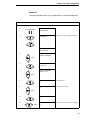
Saving Your New Configuration
The Save Config. option allows you to save up to eight custom configurations
to meet different print job requirements. Once you have changed all of the
necessary parameters, you may save them as a numbered configuration
(Example 1 on page 47) or a named configuration (Example 2 on page 49)
that can be stored and loaded later for future use. If you do not save your
configuration using the Auto Save, or this option, all of your parameter
changes will be erased when you power off the printer.
Once you have saved a custom configuration using this option, it will not be
lost if you power off the printer. You can load a configuration for a specific
print job (see “Load Config.” on page 58). You can also modify and resave it.
You may want to print your configurations (see “Print Config.” on page 59)
and store them in a safe place, such as inside the printer cabinet. If the
Protect Configs. parameter is enabled and you try to resave an existing
configuration, the new configuration will not be saved until the existing
configuration has been deleted (see “Delete Config.” on page 59).
NOTE: Once you change active emulations, any changes to the previously
selected emulation will be gone unless they have been saved.
46
Saving Your New Configuration
Example 1
This example shows how to save a configuration as a numbered
configuration, then later print it.
Step
Press
1.
Make sure the printer is on.
2.
ON LINE/CLEAR
3.
LCD
Notes
OFFLINE
QUICK SETUP
ENTER SWITCH
UNLOCKED
Allows you to make configuration changes.
+
OFFLINE
QUICK SETUP
4.
OFFLINE
CONFIG. CONTROL
UNTIL
5.
CONFIG. CONTROL
Load Config.
6.
CONFIG. CONTROL
Save Config.
UNTIL
7.
Save Config.
1*
8.
Save Config.
2
Cycle through the choices.
Save Config.
2*
The * indicates this choice is active.
OR
9.
ENTER
47
Chapter
Step
NOTE:
4
Configuration Overview
Press
LCD
Notes
We recommend that you print the configuration. To print the configuration go to Step 9. To skip this procedure
and resume printer operation, go to Step 14.
10.
CONFIG. CONTROL
Save Config.
11.
CONFIG. CONTROL
Print Config.
UNTIL
12.
Print Config.
Current
13.
Print Config.
2
Press until the desired parameter displays.
OFFLINE
CONFIG. CONTROL
The selected configuration is printed.
ENTER SWITCH
LOCKED
Locks the ENTER key.
OR
14.
ENTER
15.
+
16.
17.
48
ON LINE/CLEAR
ONLINE
Ribbon Life 100%
If you printed out the configuration, store it in a safe place. The printer is ready for operation.
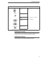
Saving Your New Configuration
Example 2
This example shows how to save a configuration as a named configuration.
Step
Press
1.
Make sure the printer is on.
2.
LCD
ON LINE/CLEAR
3.
Notes
OFFLINE
QUICK SETUP
ENTER SWITCH
UNLOCKED
Allows you to make configuration changes.
+
OFFLINE
QUICK SETUP
4.
OFFLINE
CONFIG. CONTROL
UNTIL
5.
CONFIG. CONTROL
Load Config.
6.
CONFIG. CONTROL
Name Configs.
UNTIL
7.
Name Configs.
1
The LCD flashes.
8.
Name Configs
2
You will rename config 2.
UNTIL
9.
2
2*
10.
UNTIL
2
T
Cycle through the choices until “T” displays.
49
Chapter
Step
4
Configuration Overview
Press
LCD
11.
2
T_
Saves the first character.
12.
2
TE
Cycle through the choices until “E” displays.
2
TE_
Saves the second character.
2
TES
Cycle through the choices until “S” displays.
15.
2
TES_
Saves the third character.
16.
2
TEST
Cycle through the choices until “T” displays.
2
TEST_
Saves the fourth character.
Name Configs
TEST
The configuration is renamed TEST.
UNTIL
13.
14.
UNTIL
UNTIL
17.
18.
ENTER
19.
CONFIG. CONTROL
Name Configs
20.
CONFIG. CONTROL
Save Config.
UNTIL
21.
50
Notes
Save Config.
1*
Optimizing Print Quality
Step
Press
22.
23.
LCD
Save Config.
TEST
ENTER
24.
Notes
TEST now appears as one of configuration
choices.
Saving Configuration
Save Config.
TEST*
Your configuration is saved as TEST.
ENTER SWITCH
LOCKED
Locks the ENTER key.
+
25.
ON LINE/CLEAR
ONLINE
Ribbon Life 100%
Now you have the saved configuration for later use if needed.
Optimizing Print Quality
The print quality will vary according to the typeface selected. Both text and
barcodes will print using the resolution of the typeface selected.
Optimizing Print Speed
The print speed will vary according to the typeface selected.
51
Chapter
4
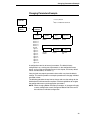
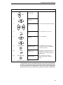
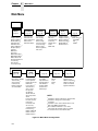
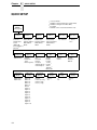
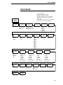
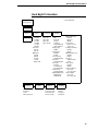
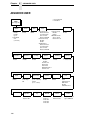
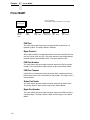
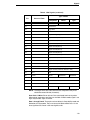
Main Menu
Main Menu
OFFLINE
QUICK
SETUP
page 54
Host Interface
Adapter Address 3
Ethernet Address 3
WLAN Address 3
ZTP Data Time 4
ZTP Wait Time 4
ZTP TearDistance 4
Graphic Spd Up
Typeface
DBCS CPI
Select LPI
DBCS ASCII Style
DBCS/ASCII Mode 1
Ribbon End Point
Reset Cmd CFG Ld
Load Config.
Save Config.
Power-Up Config.
PRINTER
CONTROL
page 102
Ribbon End Point
Open Platen @ BOF
Tear Bar Dist.
View Function 5
Unidirectional
Display Language
Accented Chars
ZTP
SETTINGS 4
page 185
CONFIG.
CONTROL
page 58
ZTP Data Time
ZTP Wait Time
ZTP Tear Distance
ZTP Function
ZTP Platen Open
HOST
INTERFACE
page 60
E-Net Adapter 3
Ethernet 3
Auto Switching*
Centronics
Dataproducts
Serial
IEEE 1284
Load Config.
Save Config.
Print Config.
Delete Config.
Power-Up Config.
Protect Configs.
Name Configs
Reset Cfg Names
Auto Save
ADVANCED
USER
page 104
Ptx Setup Option
Hex Dump Mode
Power-Up State
Downloaded Fonts
PMD Fault
Power Stacker 3
Auto Elevator 3
Auto Locking
File System
Set Sharing
Shuttle Timeout
Slow Paper Slew
Alarm
Power Saver Time
Pwr Save Control
Cancel Key
Ret. Status Port
Set Lock Key
Job Set/Typeface
Print Hist. Log
RBN Low Warn@
RBN Low Action
RBN End Action
NETWORK
SETUP 3
page 77
page 92
Adapter Address 3 LinePrinter+
Adapter Params 3
Printer Protocol
Ethernet Address 3
LQ 1600K1
Ethernet Params 3
KS2
WLAN Address 3
KSSM2
WLAN Params 3
DIAGNOSTICS
DATE 7
Printer MGMT
page 110
page 113
page 114
Printer Tests
Test Width
Paper Out Dots
System Memory
Print Statistics
Software Build
Feature File 8
Shuttle Type
Hour
Minute
Year
Month
Day
PNE Port
Mgmt Protocol
PNE Port Number 6
PNE Port Timeout 6
Status Port Numb
Mgmt Port Number
NOTE:
1
Available for Hanzi and Kanji LP+ Printers Only
for Hangul LP+ Printers Only
3
If installed
4
Available for Zero Tear Pedestal Printers only.
5 Only for P7000 Pedestal Model
6
Not available if PNE Port is set to Seria
7
If Real Time Clock (RTC) option is installed.
8 If a Feature File has been downloaded.
2 Available
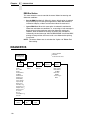
Figure 22. Main Menu Configuration
52
EMULATION
MainSpeed
Menu
Optimizing Print
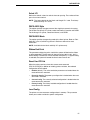
Brief descriptions follow for the first-level configuration menu options:
•
QUICK SETUP — These options allow quick access to the main printer
options used most.
•
ZTP SETTINGS These options allow you to set parameters for zero tear
pedestal printers.
•
CONFIG. CONTROL — These options allow you to save, print, load,
delete, name, and reset entire sets of configuration parameters.
•
HOST INTERFACE — These options allow you to select either the Serial
RS-232, Serial RS-422, Centronics® parallel, Data Products parallel,
Ethernet™, IEEE® 1284 parallel, or Auto Switching interface for the
printer. This menu also allows you to configure several parameters for
each interface.
•
NETWORK SETUP — This option allows you to select from Ethernet
Address option and Ethernet Parameters options.
•
EMULATION — This menu allows you to configure the options which are
available for the current operating (active) emulation.
•
PRINTER CONTROL — These options allow you to select several
operating parameters for the printer, such as the speed at which paper
will advance when slewing.
•
ADVANCED USER — These options allow you to select several
advanced operating parameters for the printer, such as the speed at
which paper will advance when slewing.
•
DIAGNOSTICS — This menu includes the diagnostic tests, system
memory, software build part number, Feature File (if one exists),
the shuttle type, and statistics of the printer.
•
DATE — This menu allows you to set the printer’s real time clock. The
parameters include hour, minute, year, month, and day.
•
PRINTER MGMT — These options allow you to select the PNE port type,
port number, port timeout period, status port number, and management
port number.
53
Chapter
4
QUICK SETUP
QUICK SETUP
* = Factory Default
1
Available for Hanzi and Kanji LP+ Printers Only
2
Available for Hangul LP+ Printers Only
3 If installed.
4
Available for Zero Tear Pedestal Printers only.
QUICK
SETUP
(from page 52)
Host
Interface
Ethernet
Address 3
Auto Switching*
Centronics
Dataproducts
Serial
IEEE 1284
E-Net Adapters 3
Ethernet 3
IP Address
Subnet Mask
Gateway Address
MAC Address
DHCP
ZTP
TearDistance 4
Graphics
Spd-Up
1060/144 Inch*
Normal*
Enhanced
Turbo
Match Typeface
LQ
Near LQ*
Normal
Hi-Speed
Super Hi-Speed
Ultra Hi-Speed
DBCS/ASCII
Mode 1
Ribbon End
Point
Reset Cmd
CFG Ld
DBCS Mode*
ASCII Mode
54
Adapter
Address 3
Darker +6
Darker +5
Darker +3
Darker +2
Darker +1
Normal
Lighter -1
Lighter -2
Lighter -3
Lighter -4
Lighter -5
Lighter -6
Lighter -7*
Lighter -8
Lighter -9
Lighter -10
IP Address
Subnet Mask
Gateway Address
MAC Address
DHCP
Typeface
Disable*
Power up config
Current config
Factory config
WLAN
Address 3
IP Address
Subnet Mask
Gateway Address
MAC Address
DHCP
DBCS
CPI
5.0 CPI
6.0 CPI
6.7 CPI*
7.5 CPI
8.5 CPI 2
9 CPI 2
10.0 CPI 2
Others CPI
ZTP
Data Time 4
.5 Sec*
1.0 - 15.0 Sec
Select
LPI
6.0 LPI*
8.0 LPI
Load
Config.
Factory*
1-8
Save
Config.
1*
2-8
ZTP
Wait Time 4
2 Sec*
3 - 10 Sec
1 Sec
DBCS ASCII
Style
Normal*
Oversize1
OCR B
Power-Up
Config.
Factory*
1-8
QUICK
Optimizing
PrintSETUP
Speed
Host Interface
The Host Interface menu enables you to select and configure interfaces
between the printer and your host computer.
Adapter Address
•
IP Address. A numeric address such as 123.45.61.23 which identifies a
printer or server in a LAN or WAN.
•
Subnet Mask. A binary value used to divide IP networks into smaller
subnetworks or subnets. This mask is used to help determine whether IP
packets need to be forwarded to other subnets.
•
Gateway Address. A gateway address is the IP address of a hardware
device (gateway) that translates data between two incompatible
networks, which can include protocol translation.
•
MAC Address. This menu item is the Manufacturer’s Assigned Number,
and is unique for each printer. It is read-only.
•
DHCP. You can enable/disable the DHCP protocol using this option, but
consult your administrator for the appropriate setting.
Ethernet Address
•
IP Address. A numeric address such as 123.45.61.23 which identifies a
printer or server in a LAN or WAN.
•
Subnet Mask. A binary value used to divide IP networks into smaller
subnetworks or subnets. This mask is used to help determine whether IP
packets need to be forwarded to other subnets.
•
Gateway Address. A gateway address is the IP address of a hardware
device (gateway) that translates data between two incompatible
networks, which can include protocol translation.
•
MAC Address. This menu item is the Manufacturer’s Assigned Number,
and is unique for each printer. It is read-only.
•
DHCP. You can enable/disable the DHCP protocol using this option, but
consult your administrator for the appropriate setting.
WLAN Address
•
IP Address. A numeric address such as 123.45.61.23 which identifies a
printer or server in a LAN or WAN.
•
Subnet Mask. A binary value used to divide IP networks into smaller
subnetworks or subnets. This mask is used to help determine whether IP
packets need to be forwarded to other subnets.
•
Gateway Address. A gateway address is the IP address of a hardware
device (gateway) that translates data between two incompatible
networks, which can include protocol translation.
•
MAC Address. This menu item is the Manufacturer’s Assigned Number,
and is unique for each printer. It is read-only.
•
DHCP. You can enable/disable the DHCP protocol using this option, but
consult your administrator for the appropriate setting.
55
Chapter
4
QUICK SETUP
ZTP Data Time
This option sets the pause time in the data stream that the ZTP requires
before moving the form to the tear bar once a print job is completed. The
values range from .5 to 15 seconds. The default is .5 seconds.
ZTP Wait Time
This option sets the minimum amount of time that the form stays at the tear
bar. This allows you time to remove the form before the form is retracted to
print the next form. The adjustable values range from 1 to 10 seconds in
increments of 1 second. The default value is 2 seconds.
ZTP TearDistance
This option sets the tear off distance from the current print position to the tear
bar. Adjustable values in increments of 1/144th of an inch range from 200 to
2880. The up and down arrows adjust the display value. When you press the
Enter key, the selected value is stored and a scale is printed to indicate the
current tear off position. The default value is 1060.
NOTE: When a new value is selected, the printer will lose the current print
position. You must reset the top of form to automatically save the new
value.
Graphics Spd-Up
This menu is used to increase (speed up) graphic printing speed by turning on
Enhanced/Turbo mode. See “Graphics Spd Up” in the Programmer’s
Reference manual.
Typeface
Sets the typeface of the printer. This key requires confirmation with the
ENTER key.
NOTE: The factory default for the Hanzi GB and Kanji SJIS LP+ is Near LQ.
The factory default for the Hangul and Hanzi Big5 LP+ is LQ.
DBCS CPI
Defines the default values for horizontal character spacing in DBCS mode.
For the Hanzi and Kanji LP+ printer, select from 5.0, 6.0, 6.7, 7.5, and Others
CPI. For the Hangul LP+ printer, selected from 5.0, 6.0, 6.7, 7.5, 8.5, 10, and
others CPI.
NOTE: The factory default for the Hanzi LP+ printer is 6.7 cpi. The factory
default for the Hangul LP+ printer is 6.0 cpi. The factory default for the
Kanji LP+ printer is 7.5 cpi.
56
QUICK
Optimizing
PrintSETUP
Speed
Select LPI
Defines the default values for vertical character spacing. The number of lines
per inch can be 6.0 or 8.0.
NOTE: The factory default for the Hanzi and Hangul LP+ is 6.0. The factory
default for Kanji LP+ is 8.0.
DBCS ASCII Style
This option specifies the appearance of the single-byte numeric characters.
For the Hanzi and Kanji LP+ printer, select from Normal, Oversize and OCRB.
For the Hangul LP+ printer, select from Normal, and OCRB.
DBCS/ASCII Mode
This option specifies the operating mode of the Hanzi printer. Refer to “Font
Attribues” in the LQ1600K Programmer's Reference Manual for more
information.
NOTE: Available for the Hanzi and Kanji LP+ printers only.
Ribbon End Point
This parameter adjusts the point at which the system will declare the ribbon
as being expended. The life count will always be from 100% to 0%, but if a
darker setting is selected 0% will be reached more quickly. If a lighter setting
is selected, the system will extend the time it takes to reach 0%.
Reset Cmd CFG Ld
When the printer receives a host data stream reset command
(ESC @ or ESC[K) in addition to resetting printer variables, the selected
configuration will be loaded.
•
Disable (default). The active emulation parameters are loaded when the
reset command is executed.
•
Power-Up Config. The power-up configuration is loaded when the reset
command is executed.
•
Current Config. The currently selected configuration is loaded when the
reset command is executed.
•
Factory Config. The factory installed configuration is loaded when the
reset command is executed.
Load Config.
The printer can store numerous configurations in memory. This parameter
allows you to select and load a specific configuration.
57
Chapter
4
ZTP SETTINGS
Save Config.
This option allows you to save up to eight configurations to meet different print
job requirements. This eliminates the need to change the parameter settings
for each new job. The configurations are stored in memory and will not be lost
if you turn off the printer. If the Protect Configs. parameter is enabled, the new
configuration will not be saved unless the existing configuration has been
deleted first. The factory default configuration cannot be changed. See
“Saving Your New Configuration” on page 46 for details.
Power-Up Config.
You can specify which of the nine configurations (Factory or 1-8) will be the
power-up configuration.
ZTP SETTINGS
See Appendix C, page 177.
CONFIG. CONTROL
The CONFIG. CONTROL menu allows you to control your printer’s
configurations according to the specifications necessary for your print jobs.
* = Factory Default
CONFIG.
CONTROL
(from page 52)
Load
Config.
Factory*
1-8
Name
Configs
1-8
1*
2-8
Current Short*
Current Full
Factory
Power-Up
All
1-8
Reset Cfg
Names
1*
2-8
All
Delete
Config.
Print
Config.
Save
Config.
1*
2-8
Power-Up
Config.
Factory*
1-8
Protect
Configs.
Disable*
Enable
Auto
Save
Enable*
Disable
Load Config.
The printer can store numerous configurations in memory. This parameter
allows you to select and load a specific configuration.
58
CONFIG.Print
CONTROL
Optimizing
Speed
Save Config.
This option allows you to save up to eight configurations to meet different print
job requirements. This eliminates the need to change the parameter settings
for each new job. The configurations are stored in memory and will not be lost
if you turn off the printer. If the Protect Configs. parameter is enabled, the new
configuration will not be saved unless the existing configuration has been
deleted first. The factory default configuration cannot be changed. See
“Saving Your New Configuration” on page 46 for details.
Print Config.
This option is used to print a listing of various stored printer configurations.
Store printouts of your configurations in a safe place for quick referral.
Delete Config.
You can delete one or all of your eight customized configurations. The factory
default configuration cannot be deleted.
Power-Up Config.
You can specify which of the nine configurations (Factory or 1-8) will be the
power-up configuration.
Protect Configs.
You can specify whether or not a new configuration should overwrite an
existing configuration when you activate the Save Configs. parameter. When
disabled (default), the new configuration will overwrite the existing
configuration. When enabled, the new configuration will not overwrite the
existing configuration, and the message “CONFIG. EXISTS / Delete First”
displays.
Name Configs
You may specify a 15-character name which can be used to refer to a
configuration. The name you enter for a configuration will be used in the Load
Config., Save Config., Print Config., Delete Config., and Power-Up Config.
menus. The name can only be cleared by using the Reset Cfg Names menu.
When you move into the Name Configs. menu, the top line of the display
shows the current configuration name. The second line of the display is
initially the same as the top line. You can modify the second line of the display
without affecting the top line until the ENTER key is pressed, which sets the
modified name.
Press the UP or DOWN ( = or > ) keys to cycle through the values available
for that character at the cursor location. Press the NEXT (<) key to move to
the next character to be modified. Press the PREV key (;) to go back to a
character you have already modified. Continue until you have entered the
name you want to give to this configuration, then press ENTER to save. The
name you entered will now represent this configuration on the printer's front
panel. To exit this menu without saving, press any key other than the ENTER
key. The configuration name will revert to the last saved value.
59
Chapter
4
HOST INTERFACE
Reset Cfg Names
You can reset specific configuration names back to the default value of the
configuration number.
Auto Save
•
Enable (default). When a change has been made to a configuration
menu, this option automatically prompts you to save or not save the
change to config #. If you are currently in the Factory Config. menus and
make a change, pressing Enter saves to Config 1 or the next available
config. and becomes the Power-Up config. If the current config is Config 1
and a menu change is made, pressing Enter will save the change to
Config 1.
•
Disable. The printer will not prompt you to save any changes made.
HOST INTERFACE
* = Factory Default
Available when an Ethernet is present.
1
HOST
INTERFACE
(from page 52)
2
Available when an Adapter is present.
Auto
Switching*
Centronics
Dataproducts
Serial
IEEE 1284
E-Net
Adapter2
(see page 61)
(see page 63)
(see page 65)
(see page 68)
(see page 74)
(see page 75)
Ethernet1
(see page 76)
The Host Interface Menu enables you to select and configure one of many
types of interfaces between the printer and your host computer. The currently
selected interface is indicated with an asterisk on the control panel message
display. Each interface has its own submenu with a set of interface
parameters which can be configured.
60
HOST INTERFACE
Auto Switching
Submenu
Auto Switching Submenu
* = Factory Default
1
= If installed
Auto Switching
(from page 60)
Parallel
Hotport
Port Type
Centronics*
(see page 63 for options)
Dataproducts
(see page 65 for options)
IEEE 1284
(see page 74 for options)
Disable
E-Net Adapter
(see page 75 for options)
Trickle Time
1/4 sec*
1/2 sec
1 sec
2 sec
4 sec
8 sec
16 sec
Off
Timeout
10 sec.*
(10-60)
Report Status
Disable*
Enable
Switch Out On
Data Timeout*
Session Close
Serial
Hotport
Port Type
RS 232*
RS 422
Disable
Trickle Time
1/4 sec*
1/2 sec
1 sec
2 sec
4 sec
8 sec
16 sec
Off
Timeout
10 sec.*
(10-60)
Report Status
Disable*
Enable
Ethernet
Hotport 1
Timeout
10 sec.*
(10-60)
Switch Out On
Data Timeout*
Session Close
Auto Switching
Gives the printer the ability to handle multiple data streams sequentially. With
Auto Switching, the printer can service hosts attached to the serial, parallel,
coax and twinax ports as if they were the only interface connected.
For example, if the host computer sends one print job to the
RS-232 serial port and a separate print job to the IEEE 1284 parallel port, the
printer's Auto Switching is able to handle both jobs, in the order they were
received. The user does not have to reconfigure the selected interface
between jobs.
61
Chapter
4
HOST INTERFACE
Port Type
Select the types of parallel, serial and/or C/T interfaces which are connected
to the printer. For example, if your printer is attached to one host with a
Centronics connection and a second host with an RS-422 serial connection,
you would select Centronics under the Parallel Hotport menu, RS-422 under
the Serial Hotport menu, and Disable under the C/T Hotport menu.
Trickle Time
When the printer is printing data from a host and a second job is received by
the printer from a different host, Trickle Time prevents the second host from
timing out while it is waiting for its data to be printed. In order to support this
feature, the port has to be able to accept data from the host and store it for
future use.
For example, if the printer is printing a job from the serial port, and then
receives a second print job from the parallel port, the data from the parallel
port will “trickle” bit by bit into the printer buffer to prevent a timeout error from
being sent back to the host connected to the parallel port.
The selected value is the time that the printer waits before getting the next
byte of data from the host. The Trickle Time value should be less than the
host time out value, but not too much shorter or else the printer fills up its
buffer too fast. This function is not applicable for C/T hotport.
Timeout
This is the value used by the printer to time out from the current port and
check the other selected port types for data to print. When the printer has not
received data from the host after a certain period of time, it needs to timeout in
order to service the other ports.
Report Status
•
Disable (default). When a fault occurs on the printer, only the active port
reports the fault to the host.
•
Enable. The port will report any fault even when it is not the current active
port.
Switch Out On
62
•
Data Timeout (default). Allows Autoswitching when no data has been
received for the selected Time Out period.
•
Session Close. Allows Autoswitching only when the Network Socket is
closed. If the Ethernet option is not installed the Network Socket is always
reported as closed and this menu option is ignored.
Centronics (Parallel) Submenu
Centronics (Parallel) Submenu
* = Factory Default
Centronics
(from page 60)
Data Bit 8
Enable*
Disable
Prime
Signal
Enable
Disable*
PI Ignored
Enable*
Disable
Data Polarity
Standard*
Inverted
Buffer Size
in K
TOF Action
Reset*
Do Nothing
1
2
4
8
16
32
64*
128
256
Resp.
Polarity
Standard*
Inverted
Auto Trickle
Disable*
Enable
Busy on
Strobe
Enable*
Disable
Latch Data
On
Leading*
Trailing
Trickle Time
1/4 sec*
1/2 sec
1 sec
2 sec
4 sec
8 sec
16 sec
Off
Data Bit 8
•
•
Enable (default). Allows access to the extended ASCII character set.
Disable. The printer interprets bit 8 of each incoming data character as a
zero, regardless of its actual setting.
PI Ignored
The PI (Paper Instruction) signal is used to control vertical paper motion.
•
Enable (default). Ignores the PI signal and treats the data as characters
or control codes.
•
Disable. Causes the printer to interpret the eight data lines as VFU
commands when the PI signal is true.
Data Polarity
The Data Polarity parameter must be set to match the data polarity of your
host computer.
•
•
Standard (default). Does not expect the host computer to invert the data.
Inverted. Expects the data received on the data lines from the host
computer to be inverted. Ones become zeros, and vice versa.
63
Chapter
4
HOST INTERFACE
Resp. Polarity
The Resp. Polarity parameter must be set to match the response polarity of
your host computer.
•
•
Standard (default). Does not invert the response signal.
Inverted. Inverts the response signal sent to the host computer.
Busy On Strobe
•
•
Enable (default). Asserts a busy signal after each character is received.
Disable. Asserts a busy signal only when the print buffers are full.
Latch Data On
Specifies whether the data is read on the leading or trailing edge of the data
strobe signal.
Prime Signal
•
Enable. The parallel port will perform a warm start (reboot) if the host
asserts the prime signal.
•
Disable (default). The parallel port will not perform a warm start (reboot) if
the host asserts the prime signal.
TOF Action
•
Reset (default). A form feed is performed before a warm start when the
prime signal is asserted from the host. This setting is used only if the
prime signal parameter is enabled.
•
Do Nothing. Nothing occurs before a warm start when the prime signal is
asserted from the host.
Buffer Size in K
Configures the amount of memory allocated for the Centronics parallel port
buffer. You can specify between 1, 2, 4, 8, 16, 32, 64, 128, and 256.
Auto Trickle
Auto Trickle is used to prevent a host computer from timing out because the
parallel interface was busy for too long. When Auto Trickle is enabled and the
printer's buffers are almost full, the printer will begin to trickle data in (at the
rate set in the Trickle Time menu) until the buffers start to empty out.
64
Dataproducts Submenu
Trickle Time
When the printer is printing data from a host and a second job is received by
the printer from a different host, Trickle Time prevents the second host from
timing out while it is waiting for its data to be printed. In order to support this
feature, the port has to be able to accept data from the host and store it for
future use.
For example, if the printer is printing a job from the serial port, and then
receives a second print job from the parallel port, the data from the parallel
port will “trickle” bit by bit into the printer buffer to prevent a timeout error from
being sent back to the host connected to the parallel port.
The selected value is the time that the printer waits before getting the next
byte of data from the host. The Trickle Time value should be less than the
host time out value, but not too much shorter or else the printer fills up its
buffer too fast. This function is not applicable for C/T hotport.
Dataproducts Submenu
* = Factory Default
Dataproducts
(from page 60)
Data Bit 8
Enable*
Disable
PI Ignored
Enable*
Disable
TOF Action
Reset*
Do Nothing
Buffer Size
in K
64*
1
2
4
8
16
32
128
256
Data
Polarity
Standard*
Inverted
Auto
Trickle
Disable*
Enable
Resp.
Polarity
Standard*
Inverted
Latch Data
On
Middle*
Trailing
Leading
Prime Signal
Disable*
Enable
Trickle
Time
1/4 sec*
1/2 sec
1 sec
2 sec
4 sec
8 sec
16 sec
Off
Data Bit 8
•
•
Enable (default). Allows access to the extended ASCII character set.
Disable. The printer interprets bit 8 of each incoming data character as a
zero, regardless of its actual setting.
65
Chapter
4
HOST INTERFACE
PI Ignored
The PI (Paper Instruction) signal is used to control vertical paper motion.
•
Enable (default). Causes the printer to interpret the eight data lines as
DVFU commands when the PI signal is true.
•
Disable. Ignores the PI signal and treats the data as characters or control
codes.
Data Polarity
The Data Polarity parameter must be set to match the data polarity of your
host computer.
•
•
Standard (default). Does not expect the host computer to invert the data.
Inverted. Expects the data received on the data lines from the host
computer to be inverted. Ones become zeros, and zeros become ones.
Resp. Polarity
The Response Polarity parameter must be set to match the response polarity
of your host computer.
•
•
Standard (default). Does not invert the response signal.
Inverted. Inverts the response signal sent to the host computer.
Latch Data On
Specifies whether the data is read on the leading, middle, or trailing edge of
the data strobe signal. The default is Middle.
Prime Signal
•
Disable (default). The parallel port will not perform a warm start (reboot) if
the host asserts the prime signal.
•
Enable. The parallel port will perform a warm start (reboot) if the host
asserts the prime signal.
TOF Action
•
Reset (default). A form feed is performed before a warm start when the
prime signal is asserted from the host. This setting is used only if the
prime signal parameter is enabled.
•
Do Nothing. Nothing occurs before a warm start when the prime signal is
asserted from the host.
Buffer Size in K
Configures the amount of memory allocated for the Dataproducts parallel port
buffer. You can specify between 1, 2, 4, 8, 16, 32, 64, 128, and 256 Kbytes.
66
Dataproducts Submenu
Auto Trickle
Auto Trickle is used to prevent a host computer from timing out because the
parallel interface was busy for too long. When Auto Trickle is enabled and the
printer's buffers are almost full, the printer will begin to trickle data in (at the
rate set in the Trickle Time menu) until the buffers start to empty out.
Trickle Time
When the printer is printing data from a host and a second job is received by
the printer from a different host, Trickle Time prevents the second host from
timing out while it is waiting for its data to be printed. In order to support this
feature, the port has to be able to accept data from the host and store it for
future use.
For example, if the printer is printing a job from the serial port, and then
receives a second print job from the parallel port, the data from the parallel
port will “trickle” bit by bit into the printer buffer to prevent a timeout error from
being sent back to the host connected to the parallel port.
The selected value is the time that the printer waits before getting the next
byte of data from the host. The Trickle Time value should be less than the
host time out value, but not too much shorter or else the printer fills up its
buffer too fast. This function is not applicable for C/T hotport.
67
Chapter
4
HOST INTERFACE
Serial Submenu
* = Factory Default
Serial
(from page 60)
Interface
Type
RS 232*
RS 422
Data Term
Ready
True*
On-Line and BNF
Off-Line or BF
On-Line
False
One Char
Enquiry
Disable*
Enable
Data
Protocol
Baud
Rate
XON/XOFF*
ETX/ACK
ACK/NAK
Series1 1 Char
Series1 2 Char
ENQ/ACK
DTR
9600 Baud*
19200 Baud
38400 Baud
57600 Baud
115200 Baud
600 Baud
1200 Baud
2400 Baud
4800 Baud
Request to
Send
Buffer Size
in K
On-Line and BNF*
Off-Line or BF
On-Line
False
True
1
2
4
8
16*
32
64
128
256
Word
Length 8
8*
7
Stop
Bits 1
1*
2
Poll
Character
00 Hex*
(0-FF hex)
Parity
None*
Odd
Even
Mark
Sense
Poll
Response
0 ms*
(0-30 ms)
Idle
Response
Disable*
Enable
Framing
Errors
Enable*
Disable
Interface Type
This parameter allows you to select either the RS-232 or RS-422 serial port
interface. The default is RS-232.
68
Serial Submenu
Data Protocol
You can select one of the following serial interface protocols to meet the host
interface requirements.
•
XON / XOFF (default). The printer controls the flow of communication
from the host by turning the transmission on and off. In some situations,
such as when the buffer is full or the timing of signals is too slow or too
fast, the printer will tell the host to stop transmission by sending an XOFF
character. An XOFF character is sent when the number of empty bytes in
the buffer is less than or equal to 25 percent of the buffer size. If the host
keeps sending data after an XOFF is sent, the printer firmware will
continue to send an XOFF for every 16 characters received. When
cleared, the printer will resume receiving data (XON). The data does not
have any End of Text codes;
XON / XOFF is a non-block protocol.
•
ETX / ACK. End of Text / Acknowledge. The host controls the flow of
communication to the printer by sending a block of data and ending the
block with an End of Text (ETX) signal. When the printer receives the ETX
signal, it will acknowledge the ETX, thereby acknowledging it has
received the entire block of data.
•
ACK / NAK. ACK means acknowledge; the device acknowledges it has
accepted a transmission. NAK means negative acknowledge; the device
did not receive the transmission.
SERIES1 1 CHAR. The printer controls the flow of communication from
the host by turning the transmission on and off using response characters
sent to the host. If the number of valid bytes in the buffer reaches 75
percent of the buffer size, the online or offline and buffer full response
character is sent. If the buffer is completely full, an online or offline buffer
full response is sent every time a character is sent from the host.
Whenever the printer state changes to online or offline, the appropriate
response character is sent. If the idle response option is enabled, the
printer will send a response character every two seconds while the
number of valid bytes in the buffer is less than 75 percent of the buffer
size. If a poll character is received (configurable from the Poll Character
xx Hex option on the front panel from hex 0 through FF), the printer will
send a response character n milliseconds later (configurable from the Poll
Character xx MS on the front panel from 0 through 30). This n
milliseconds is called the poll delay. The poll character will be removed
from the input data stream and will not be processed. This may cause
problems with the transmission of binary data (e.g., control codes, bit
image, etc.). If a poll delay is started due to the receipt of a poll character
and another poll character is received, the second poll character has no
effect and is removed from the input data stream. If a transition (from
buffer full to empty or online to offline) occurs during a poll delay, the new
printer state will be sent at the end of the poll delay.
69
Chapter
4
HOST INTERFACE
The response characters are described in Table 2.
Table 2. Series1 1 Char Response Characters
Printer State
Online and Buffer Empty
•
Response
CR
Online and Buffer Full
3
Offline and Buffer Empty
0
Offline and Buffer Full
2
SERIES1 2 CHAR. This protocol behaves exactly the same as the
Series1 Char except there is a two-character response to the host. The
response characters are described in Table 3.
Table 3. Series1 2 Char Response Characters
Printer State
70
Response
Online and Buffer Empty
1 CR
Online and Buffer Full
3 CR
Offline and Buffer Empty
0 CR
Offline and Buffer Full
2 CR
•
ENQ / ACK. ENQ selects odd dot plot mode to print dots in odd
numbered dot columns for normal density plotting. It defines certain data
between the next and last paper motion commands as odd dot plot data.
ACK selects line spacing of 1/8” or 7/72” for current line only.
•
DTR. The printer controls the data flow by sending this hardware signal to
the host. If there is enough room in the printer buffer, the printer will send
a high signal; if the buffer is full, the printer will send a low signal. DTR
tells the host if it is safe to send more data. (If the host sends data during
an unsafe condition, data will be lost.) DTR is not available when RS-422
is selected.
Serial Submenu
Baud Rate
Sets the baud rate of the serial interface in the printer. Baud rate is the speed
at which serial data is transferred between the host computer and the printer.
The choices for the RS-232 and RS-422 interfaces are 600, 1200, 2400,
4800, 9600, 19200, 38400, 57600, and 115200 Baud. The default is 9600
Baud.
NOTE: If you select a baud rate that is greater than 19200, you may need to
use RS-422 or select a lower baud rate to prevent data loss. You also
may need to increase the Buffer Size in K parameter from the default
(16 Kbyte) to improve performance.
Word Length
Sets the length of the serial data word. The length of the data word can be set
to 7 or 8 bits, and must match the corresponding data bits setting in the host
computer.
Stop Bits 1
Sets the number of stop bits in the serial data word. Either one or two stop bits
can be selected. The setting must match the corresponding stop bit setting in
the host computer.
Parity
Set for odd parity, even parity, mark, sense, or no parity. The setting must
match the corresponding parity setting in the host computer.
Data Term Ready
This configuration is part of hardware flow control and determines when the
Data Terminal Ready (DTR) signal is generated. This signal indicates if the
printer is ready to receive data.
•
•
True (default). Continuously asserts the DTR signal.
•
Off Line or BF (buffer full). Asserts the DTR signal when the printer is
offline or the internal serial buffer is full.
•
•
On Line. Asserts the DTR signal when the printer is online.
On Line and BNF (buffer not full). Asserts the DTR signal when the
printer is online and the internal serial buffer is not full.
False. Never asserts the DTR signal.
71
Chapter
4
HOST INTERFACE
Request To Send
This configuration is part of hardware flow control and determines when the
Request to Send (RTS) signal is generated. This signal indicates whether or
not the printer is ready to receive data.
•
On Line and BNF (default). Asserts the RTS signal when the printer is
online and the internal serial buffer is not full.
•
Off Line or BF. Asserts the RTS signal when the printer is offline or the
internal serial buffer is full.
•
•
•
On Line. Asserts the RTS signal when the printer is online.
False. Never asserts the RTS signal.
True. Continuously asserts the RTS signal.
Buffer Size in K
This option configures the amount of memory allocated for the serial port
buffer. You may specify between 1, 2, 4, 8, 16, 32, 64, 128, and 256.
NOTE: If you select a baud rate that is 19200 or greater, you may need to
increase the Buffer Size in K to improve performance.
Poll Character
This option is for the Series1 protocol. Whenever the printer receives this
character, it sends a response to the host indicating the current state of the
printer (see Series1 protocol). It may be configured from 0 through FF
hexadecimal.
Poll Response
This option is for the Series1 protocol. After receiving a poll character, the
printer will wait the poll response time in milliseconds before sending the
response. It may be configured from 0 through 30.
Idle Response
This option is for the Series1 protocol.
•
•
72
Disable (default)
Enable. The printer will send a response character every two seconds
while the number of valid bytes in the buffer is less than 75 percent of the
buffer size.
Serial Submenu
One Char Enquiry
The One Char Enquiry mode uses the Poll Character to detect a request from
the host and sends a response back to the host. This option also allows you to
turn on and off this feature.
Table 4. One Char Enquiry Response Characters
Printer State
Response (hex)
Online and Buffer Not Full
22
Online and Buffer Full
23
Offline and Buffer Not Full
20
Offline and Buffer Full
21
The Poll Character is removed from the data stream. If the Data Protocol is
set to ETX/ACK, ACK/NAK, or Series 1, One Char Enquiry is automatically
disabled.
Framing Errors
Possible errors that can occur when the printer’s serial interface settings do
not match those of the host computer.
•
Enable (default). If a framing error occurs, a fault message will display on
the control panel.
•
Disable. If a framing error occurs, a fault message will not display on the
control panel.
73
Chapter
4
HOST INTERFACE
IEEE 1284 Parallel (Bidirectional) Submenu
* = Factory Default
IEEE 1284
(from page 60)
Prime
Signal
TOF
Action
Enable
Disable*
Reset*
Do Nothing
Buffer Size
in K
1
2
4
8
16
32
64*
128
256
Auto Trickle
Disable*
Enable
Trickle
Time
1/4 sec*
1/2 sec
1 sec
2 sec
4 sec
8 sec
16 sec
Off
Offline
Process
Disable*
Enable
The IEEE 1284 interface is faster and more versatile than Centronics and
supports bidirectional communication. Configuration of this interface is
controlled from the host. Refer to ΙΕΕΕ 1284 Παραλλελ Ιντερφαχε
ον παγε 117 more details about the available modes (Compatibility, Nibble,
and Byte).
Prime Signal
•
Disable (default). The parallel port will not perform a warm start (reboot) if
the host asserts the prime signal.
•
Enable. The parallel port will perform a warm start (reboot) if the host
asserts the prime signal.
TOF Action
•
Reset (default). A form feed is performed before a warm start when the
prime signal is asserted from the host. This setting is used only if the
prime signal parameter is enabled.
•
Do Nothing. Nothing occurs before a warm start when the prime signal is
asserted from the host.
Buffer Size in K
This option configures the amount of memory allocated for the IEEE 1284
parallel port buffer. You can specify between 1, 2, 4, 8, 16, 32, 64, 128, and
256 Kbytes. The default is 64 K.
Auto Trickle
Auto Trickle is used to prevent a host computer from timing out because the
parallel interface was busy for too long. When Auto Trickle is enabled and the
printer's buffers are almost full, the printer will begin to trickle data in (at the
rate set in the Trickle Time menu) until the buffers start to empty out.
74
E-Net Adapter Submenu
Trickle Time
When the printer is printing data from a host and a second job is received by
the printer from a different host, Trickle Time prevents the second host from
timing out while it is waiting for its data to be printed. In order to support this
feature, the port has to be able to accept data from the host and store it for
future use.
For example, if the printer is printing a job from the serial port, and then
receives a second print job from the parallel port, the data from the parallel
port will “trickle” bit by bit into the printer buffer to prevent a timeout error from
being sent back to the host connected to the parallel port.
The selected value is the time that the printer waits before getting the next
byte of data from the host. The Trickle Time value should be less than the
host time out value, but not too much shorter or else the printer fills up its
buffer too fast. This function is not applicable for C/T hotport.
Offline Process
•
Disable (the default). When set to disable, the printer does not process
parallel/network data while offline.
•
Enable. When set to enable, the printer continues to process (but not
print) the current network/parallel job while the printer is offline until the
printer's buffer is full.
E-Net Adapter Submenu
* = Factory Default
E-Net Adapter
(from page 60)
Buffer Size
in K
64*
1
2
4
8
16
32
128
256
The E-Net Adapter interface allows you to locate the printer on a LAN rather
than attach the host directly into the printer. The detailed configuration of this
option is given in the Network Interface Card User's Manual.
75
Chapter
4
HOST INTERFACE
Buffer Size in K
This option configures the amount of memory allocated for the Ethernet
buffer. You can specify between 1, 2, 4, 8, 16, 32, 128, and 256 Kbytes. The
default is 64 Kbytes.
Ethernet Submenu
* = Factory Default
Ethernet
(from page 60)
Buffer Size
in K
16*
1-16
The Ethernet interface allows you to locate the printer on a LAN rather than
attach the host directly into the printer. The detailed configuration of this
option is given in the Network Interface Card User's Manual.
Buffer Size in K
This option configures the amount of memory allocated for the Ethernet
buffer. You can specify between 1 and 16 Kbytes, in 1-Kbyte increments.
The default is 16 Kbytes.
76
ADAPTER ADDRESS
NETWORK SETUP MENU
NETWORK
SETUP
(from page 52)
ADAPTER
ADDRESS 1
See page 77.
WLAN
PARAMS 3
See page 85.
ADAPTER
PARAMS 1
See page 78.
ETHERNET
ADDRESS 2
See page 81.
WLAN
KERBEROS 4
See page 89.
ETHERNET
PARAMS 2
See page 82.
WLAN
ADDRESS 3
See page 84.
WLAN
LEAP 5
See page 91.
1
Only if the Ethernet Adapter feature is installed.
if the Integrated Ethernet feature is installed.
3 Only if the Wireless Adapter feature is installed.
4 Only if a Symbol radio card is installed.
5 Only if a Cisco radio card is installed.
2 Only
ADAPTER ADDRESS
* = Factory Default
ADAPTER
ADDRESS
(from page 77)
IP Address
Subnet
Mask
xxx.xxx.xxx.xxx xxx.xxx.xxx.xxx
Gateway
Address
xxx.xxx.xxx.xxx
MAC
Address
hhhhhhhhhhhh
DHCP
Disable*
Enable
IP Address
A numeric address such as 123.45.61.23 which identifies a printer or server in
a LAN or WAN.
Subnet Mask
A binary value used to divide IP networks into smaller subnetworks or
subnets. This mask is used to help determine whether IP packets need to be
forwarded to other subnets.
77
Chapter
4
NETWORK SETUP MENU
Gateway Address
A gateway address is the IP address of a hardware device (gateway) that
translates data between two incompatible networks, which can include
protocol translation.
MAC Address
This menu item is the Manufacturer’s Assigned Number, and is unique for
each printer. It is read-only.
DHCP
You can enable/disable the DHCP protocol using this option, but consult your
administrator for the appropriate setting.
The options include:
•
•
Disable (default)
Enable.
ADAPTER PARAMS
ADAPTER
PARAMS
(from page 77)
* = Factory Default
1 If Installed
Novell
Protocol
Nest Serv
Type
Enable*
Disable
Auto*
Bindery
NDS
IPDS
Data Port 1
5001*
1023-65535
NetBIOS
Protocol
Enable*
Disable
Novell
Frame
ASCII
Data Port
Ethernet 802.2*
802.2 Snap
Auto Sensing
Ethernet II
Ethernet 802.3
9100*
1023 - 65535
Keep Alive
Timer
Ethernet
Speed
3 Minutes*
2 - 10 Minutes
Auto Select*
10 Half Duplex
10 Full Duplex
100 Half Duplex
100 Full Duplex
Job Control
Standard*
Enhanced
Off
You may enable or disable the Novell or NetBIOS Protocols within this menu,
as well as selecting which Novell Frame scheme to use in processing Novell
signals. See the Novell chapter in the Network Interface Card User's Manual
for more details.
78
ADAPTER PARAMS
Novell Protocol
This option determines whether the Novell protocol will be available. The
selections are as indicated below:
•
Enable (default). Makes the Novell protocol available with the ethernet
installed.
•
Disable. Makes the Novell protocol unavailable during printer operation.
Nest Serv Type
You can change the Nest Server using this option, but consult your
administrator for the appropriate setting.
The options are Auto (default), Bindery, and NDS.
NetBIOS Protocol
This option determines whether the NetBIOS protocol will be available. The
selections are as indicated below:
•
Enable (default). Makes the NetBIOS protocol available with the ethernet
installed.
•
Disable. Makes the NetBIOS protocol unavailable during printer
operation.
Novell Frame
This selection determines which framing scheme will be used in processing
Novell signals.
•
•
•
•
•
Ethernet 802.2 (default)
802.2 Snap
Auto Sensing
Ethernet II
Ethernet 802.3
ASCII Data Port
This option sets the port number for ASCII print jobs. The data port number
needs to match your host system setting.
•
•
9100 (default)
1023 - 65535
IPDS Data Port
This option allows you to set the port number for IPDS print jobs only if the
IPDS option is installed.
The range is 0 - 5000, and the factory default is 5001.
79
Chapter
4
NETWORK SETUP MENU
Keep Alive Timer
This is the time that the Keep Alive Timer will run. With the Keep Alive Timer
on, the tcp connection will stay connected even after the print job has
terminated.
•
•
3 Minutes (default)
2 - 10 Minutes
Ethernet Speed
This menu option only appears if a 10/100Base-T network interface card
(NIC) is installed. The Ethernet Speed menu allows compatibility with different
systems and networks. The factory default is Auto Select.
•
Auto Select. (default) This setting tells the 10/100Base-T NIC to perform
an auto detection scheme and configure itself to be 10 Half Duplex, 10
Full Duplex, 100 Half Duplex, or 100 Full Duplex.
•
10 Half Duplex. Tells the 10/100Base-T NIC to communicate at 10
Megabits per second using half duplex.
•
10 Full Duplex. Tells the 10/100Base-T NIC to communicate at 10
Megabits per second using full duplex.
•
100 Half Duplex. Tells the 10/100Base-T NIC to communicate at 100
Megabits per second using half duplex.
•
100 Full Duplex. Tells the 10/100Base-T NIC to communicate at 100
Megabits per second using full duplex.
Job Control
The job control mode has three options:
80
•
Standard (default). The NIC waits for the printer to finish receiving the
current job before sending another job. The status line shows “done”
when the job is completely received by the NIC. This is the default.
•
Enhanced. The NIC waits for the printer to finish receiving the current job
before sending another job. The status line shows “done” when the job is
fully printed.
•
Off. No job synchonization between the NIC and the printer.
ETHERNET ADDRESS
ETHERNET ADDRESS
* = Factory Default
ETHERNET
ADDRESS
(from page 77)
IP Address
Subnet
Mask
xxx.xxx.xxx.xxx
xxx.xxx.xxx.xxx
Gateway
Address
xxx.xxx.xxx.xxx
MAC
Address
hhhhhhhhhhhh
DHCP
Disable*
Enable
IP Address
A numeric address such as 123.45.61.23 which identifies a printer or server in
a LAN or WAN.
Subnet Mask
A binary value used to divide IP networks into smaller subnetworks or
subnets. This mask is used to help determine whether IP packets need to be
forwarded to other subnets.
Gateway Address
A gateway address is the IP address of a hardware device (gateway) that
translates data between two incompatible networks, which can include
protocol translation.
MAC Address
This menu item is the Manufacturer’s Assigned Number, and is unique for
each printer. It is read-only.
DHCP
You can enable/disable the DHCP protocol using this option, but consult your
administrator for the appropriate setting.
The options include:
•
•
Disable (default)
Enable.
81
Chapter
4
NETWORK SETUP MENU
ETHERNET PARAMS
ETHERNET
PARAMS
(from page 77)
NetBIOS
Protocol
Enable*
Disable
* = Factory Default
1
If Installed
ASCII
Data Port
9100*
1023 - 65535
IPDS Data
Port 1
5001*
1023 - 65535
Keep Alive
Timer
Ethernet
Speed
3 Minutes*
2 - 10 Minutes
Auto Select*
10 Half Duplex
10 Full Duplex
100 Half Duplex
100 Full Duplex
Job Control
Standard*
Enhanced
Off
The ETHERNET PARAMS menu helps your printer communicate on a
network.
For information on assigning the IP Address, Gateway Address, Subnet
Mask, and MAC Address, refer to the Network Interface Card User's Manual.
NetBIOS Protocol
This option determines whether the NetBIOS protocol will be available. The
selections are as indicated below:
•
Enable (default). Makes the NetBIOS protocol available with the ethernet
installed.
•
Disable. Makes the NetBIOS protocol unavailable during printer
operation.
ASCII Data Port
This option sets the port number for ASCII print jobs. The data port number
needs to match your host system setting.
•
•
9100 (default)
1023 - 65535
IPDS Data Port
This option allows you to set the port number for IPDS print jobs only if the
IPDS option is installed.
The range is 1023 - 65535, and the factory default is 5001.
Keep Alive Timer
This is the time that the Keep Alive Timer will run. With the Keep Alive Timer
on, the tcp connection will stay connected even after the print job has
terminated.
•
•
82
3 Minutes (default)
2 - 10 Minutes
ETHERNET PARAMS
Ethernet Speed
This menu option only appears if a 10/100Base-T network interface card
(NIC) is installed. The Ethernet Speed menu allows compatibility with different
systems and networks. The factory default is Auto Select.
•
Auto Select. (default) This setting tells the 10/100Base-T NIC to perform
an auto detection scheme and configure itself to be 10 Half Duplex, 10
Full Duplex, 100 Half Duplex, or 100 Full Duplex.
•
10 Half Duplex. Tells the 10/100Base-T NIC to communicate at 10
Megabits per second using half duplex.
•
10 Full Duplex. Tells the 10/100Base-T NIC to communicate at 10
Megabits per second using full duplex.
•
100 Half Duplex. Tells the 10/100Base-T NIC to communicate at 100
Megabits per second using half duplex.
•
100 Full Duplex. Tells the 10/100Base-T NIC to communicate at 100
Megabits per second using full duplex.
Job Control
The job control mode has three options:
•
Standard (default). The NIC waits for the printer to finish receiving the
current job before sending another job. The status line shows “done”
when the job is completely received by the NIC. This is the default.
•
Enhanced. The NIC waits for the printer to finish receiving the current job
before sending another job. The status line shows “done” when the job is
fully printed.
•
Off. No job synchonization between the NIC and the printer.
83
Chapter
4
NETWORK SETUP MENU
WLAN ADDRESS
* = Factory Default
WLAN
ADDRESS
(from page 77)
IP Address
xxx.xxx.xxx.xxx
Subnet
Mask
xxx.xxx.xxx.xxx
Gateway
Address
xxx.xxx.xxx.xxx
MAC
Address
hhhhhhhhhhhh
DHCP
Disable*
Enable
IP Address
A numeric address such as 123.45.61.23 which identifies a printer or server in
a LAN or WAN.
Subnet Mask
A binary value used to divide IP networks into smaller subnetworks or
subnets. This mask is used to help determine whether IP packets need to be
forwarded to other subnets.
Gateway Address
A gateway address is the IP address of a hardware device (gateway) that
translates data between two incompatible networks, which can include
protocol translation.
MAC Address
This menu item is the Manufacturer’s Assigned Number, and is unique for
each printer. It is read-only.
DHCP
You can enable/disable the DHCP protocol using this option, but consult your
administrator for the appropriate setting.
The options include:
•
•
84
Disable (default)
Enable.
WLAN PARAMS
WLAN PARAMS
* = Factory Default
Only when 40 Bits is selected
2
Only when 128 Bits is selected
3
Only when a Symbol radio card is installed.
4
Only when a Cisco radio card is installed.
5 Read only
6
Not displayed if LA5127 radio card is installed.
7
Only if LA5127 radio card is installed.
1
WLAN
PARAMS
(from page 77)
Signal
Strength 5
Operation
Mode 6
Infrastructure*
Pseudo IBSS
Ad Hoc
0%
Ant. Diversity 6
Diverse
Primary*
Auxiliary
Auth
Method
Open*
Shared
Kerberos 3
LEAP 4
Default WEP
Keys
SSID
Name
Default*
Short
Long
Power
Mgmt
Primary*
Auxiliary
WEP Key 1
0 ms.*
100 ms.
200 ms.
300 ms.
400 ms.
500 ms.
600 ms.
700 ms.
800 ms.
900 ms.
1000 ms.
Key Format
Hexadecimal*
ASCII
Key Width
128 Bits*
40 Bits
Byte 1 - Byte 5 1
Byte 1 - Byte 13 2
Key Format
Hexadecimal*
ASCII
Key Width
128 Bits*
40 Bits
Byte 1 - Byte 5 1
Byte 1 - Byte 13 2
WPA
Mode 7
Transmit
Power
100%*
0 - 100 %
WEP Key 3
WEP Key 2
Disable*
Personal
WPA P-Phs
(31-32) 7
Auto-negotiate*
1Mb/Sec
2Mb/Sec
5.5Mb/Sec
11Mb/Sec
Antenna 7
Key Format
Hexadecimal*
ASCII
Key Width
128 Bits*
40 Bits
Byte 1 - Byte 5 1
Byte 1 - Byte 13 2
WPA
Cipher 7
Channel 6
Min xfer
Rate
SSID Name (01 - 15)
SSID Name (16 - 30)
SSID Name (31 - 32)
Preamble 6
Reset WEP
Keys
Reset SSID
Name
Default*
1 - 15
Internat.
Mode
Disable*
Enable
WEP Key 4
Key Format
Hexadecimal*
ASCII
Key Width
128 Bits*
40 Bits
Byte 1 - Byte 5 1
Byte 1 - Byte 13 2
WPA
P-Phs (01-15) 7
WPA P-Phs
(16-30) 7
TKIP*
AES
TKIP+AES
Reset WPA
P-Phs 7
85
Chapter
4
NETWORK SETUP MENU
Signal Strength
This menu displays the strength of the wireless signal.
NOTE: This is a display value only and cannot be changed.
Operation Mode
Allows you to select the way the Wireless option communicates:
•
•
Infrastructure (default). The Wireless option must go through a server.
•
Ad Hoc. Standard, peer-to-peer communication (without a server). The
two peers can be from different manufacturers.
Pseudo IBSS. Proprietary, peer-to-peer communication (without a
server). The two peers must be specific to one manufacturer.
SSID Name
A 1 - 32 character, case sensitive string that identifies the group the printer
talks to.
NOTE: The SSID name may be edited in three parts (1-15), (16-30), and
(31-32).
For each part of the SSID name, press the MICRO UP or MICRO DOWN
keys to cycle through the values available for that character at the cursor
location. Press the SCROLL UP key to move to the next character to be
modified. Press the SCROLL DOWN key to go back to the name you want to
give to this SSID name, then press ENTER to save. The name you entered
will now represent this SSID name on the printer’s front panel. To exit this
menu without saving, press any key other than the ENTER key. The SSID
name will revert to the last saved value.
Reset SSID Name
Allows you to reset the SSID name.
Min Xfer Rate
Allows you to set the minimum speed at which the Wireless Option will accept
a connection (in million bits per second). The options are:
•
•
•
•
•
Auto-negotiate (default)
1Mb/Sec.
2Mb/Sec.
5.5Mb/Sec
11Mb/Sec
Channel
Allows you to select the RF channel. The options are Default (the factory
default) and 1-15.
86
WLAN PARAMS
Ant. Diversity
The type of antenna used:
•
Diverse. Select when you want to use the antenna with the best
reception.
•
Primary (default). Select when you want to use the Primary antenna on
the server.
•
Auxiliary. Select when you want to use the Auxiliary antenna on the
server.
Preamble
The length of the preamble in transmit packets.
•
•
•
Default. The Wireless option automatically determines the length.
Short. For newer printers which can handle higher transer rate speeds.
Long. For older printers which cannot handle higher transfer rate speeds.
Antenna
•
Primary (default). Select when you want to use the primary antenna on
the RF card.
•
Auxiliary. Select when you want to use the Auxiliary antenna on the RF
card.
Power Mgmt
This allows you to set power-save mode and sleep time. A value specifying
the sleep time in milliseconds will be provided. If set to zero, power-save
mode will be disabled. The range includes:
•
•
0 ms. (default)
100 ms. - 1000 ms.
Transmit Power
The power level as a percentage of full power (0 - 100%).
Internat. Mode
When enabled, the Wireless option adapts to international frequency
requirements in Europe. The options include:
•
•
Disable (default)
Enable
87
Chapter
4
NETWORK SETUP MENU
Auth Method
This feature allows the user to select the authentication method used for the
wireless network interface.
•
•
•
Open (the default). Selects open authentication.
•
LEAP. Selects LEAP authentication (for use with a Cisco RF card
installed).
Shared. Selects shared key authentication.
Kerberos. Selects Kerberos authentication (for use when a Symbol RF
card is installed).
WEP Key 1 Through WEP Key 4
•
WEP Key Format. Allows you to format the WEP keys in ASCII or
hexadecimal code. The default is hexadecimal.
•
WEP Key Width. This is the encryption strength. The options are 40 Bits
and 128 Bits; 40 Bits are weaker and 128 Bits are stronger.
NOTE: If you select 40 Bits, the WEP key BYTE6 through WEP Key BYTE13
menus will not display.
The default is 128 Bits.
•
WEP Key BYTE1 through BYTE13. These are the individual characters
of the encryption key.
Default WEP Key
This feature enables you to encrypt (scramble) information for security
purposes. With this feature, you can set up to four encryption keys, in either
ASCII or hexadecimal format, and in either 40 or 128 bits. (The more bits you
choose, the more difficult it will be to decode the information.)
NOTE: None of the WEP Key Configuration menus display on the
configuration printout.
Reset WEP Keys
Allows you to reset all four WEP keys (WEP Key 1 through WEP Key 4) at
one time.
WPA Mode
Selects the WPA wireless security mode.
•
•
88
Disable (the default). WPA security is disabled.
Personal. Selects personal or pre-shared key mode for WPA security.
WLAN KERBEROS
WPA Cipher
Selects the WPA wireless security cipher setting. Options include:
•
•
•
TKIP (the default)
AES
TKIP+AES
WPA P-Phs
Allows you to set the individual bytes of the WPA passphrase.
Reset WPA P-Phs
Allows you to reset all 32 bytes of the WPA passphrase at once.
WLAN KERBEROS
WLAN
Kerberos 1
(from page 77)
* = Factory Default
1 = Only if a Symbol radio card is installed.
Kerberos
Enable
Kerb.
Passwd
Disable*
Enable
Reset
Kerb. Pwd
Kerb Pwd(01-15)
Kerb Pwd (16-30)
Kerb Pwd (31-40)
Ticket Lifetime
KDC Port
Number
88*
0-65535
Clock Skew
Clock Skew Units
Seconds*
Minutes
Clock Skew (Sec)
300*
60, 65, 70, ..., 900
Renew
Lifetime
Tckt Life Units
Seconds*
Minutes
Hours
Days
Tckt Life (SEC)
43200*
300, 305, 310, ..., 259200
Renew Life Units
Seconds*
Minutes
Hours
Days
Renew Life (SEC)
0*
0, 5, 10, ..., 604800
Kerberos Enable
•
Disable (the default). Disables Kerberos authentication in the wireless
network interface.
•
Enable. Enables Kerberos authentication in the wireless network
interface.
89
Chapter
4
NETWORK SETUP MENU
Kerb. Passwd
•
Kerb. Pwd (01-15). The first 15 characters of the Kerberos password
(maximum number of characters is 40).
•
Kerb. Pwd (16-30). Characters 16 to 30 of the Kerberos password
(maximum number of characters is 40).
•
Kerb. Pwd (31-40). Characters 31 to 40 of the Kerberos password
(maximum number of characters is 40).
Reset Kerb. Pwd
Resets the Kerberos password to an empty string.
KDC Port Number
KDC (Key Distribution Center) port number is the 2-byte UDP/TCP port used
for Kerberos Communication.
The range is 0-65535, and the factory default is 88.
Clock Skew
Sets the maximum allowable amount of time in seconds or minutes that
Kerberos authentication will tolerate before assuming that a Kerberos
message is valid. The range for Seconds is 60-900, and the default is 300.
The range for Minutes is 1-15, and the default is 5.
Ticket Lifetime
Sets the maximum allowable amount of time in Seconds, Minutes, Hours, or
Days that a ticket obtained from the Kerberos server is valid before getting a
new one.
•
•
•
•
•
Seconds. The range is 300-259200, and the default is 43200.
Minutes. The range is 5-4320, and the default is 720.
Hours. The range is 1-72, and the default is 12.
Days. The range is 1-3, and the default is 1.
Tckt Life (SEC). The ticket lifetime unit in seconds. The default is 43200.
Renew Lifetime
Sets the maximum allowable amount of time in Seconds, Minutes, Hours, or
Days before warning that a new Kerberos password is needed.
•
•
•
•
•
90
Seconds. The range is 0-604800, and the default is 0.
Minutes. The range is 0-10080, and the default is 0.
Hours. The range is 1-168, and the default is 0.
Days. The range is 0-7, and the default is 0.
Renew Life (SEC). Renew lifetime unit in seconds. The default is 0.
WLAN LEAP
WLAN LEAP
* = Factory Default
1 = Only if a Symbol radio card is installed.
2 = Only if a Cisco radio card is installed.
WLAN
LEAP 2
(from page 77)
Auth Method
Open*
Shared
Kerberos 1
LEAP 2
LEAP
Username
Reset LEAP
User
LEAP Username (01-15)
LEAP Username (16-30)
LEAP Username (31-32)
LEAP
Password
Reset LEAP
Password
LEAP Password (01-15)
LEAP Password (16-30)
LEAP Password (31-32)
Auth Method
This feature allows the user to select the authentication method used for the
wireless network interface.
•
•
•
Open (the default). Selects open authentication.
•
LEAP. Selects LEAP authentication (for use with a Cisco RF card
installed).
Shared. Selects shared key authentication.
Kerberos. Selects Kerberos authentication (for use when a Symbol RF
card is installed).
LEAP Username
•
LEAP Username (01-15). The first 15 characters of the LEAP user name
(maximum number of characters is 32).
•
LEAP Username (16-30). Characters 16 to 30 of the LEAP user name
(maximum number of characters is 32).
•
LEAP User (31-32). Characters 31 to 32 of the LEAP user name
(maximum number of characters is 32).
Reset LEAP User
Resets the LEAP user name to an empty string.
LEAP Password
•
LEAP Password (01-15). The first 15 characters of the LEAP password
(maximum number of characters is 32).
•
LEAP Password (16-30). Characters 16 to 30 of the LEAP password
(maximum number of characters is 32).
•
LEAP Password (31-32). Characters 31 to 32 of the LEAP password
(maximum number of characters is 32).
Reset LEAP Password
Resets the LEAP password to an empty string.
91
Chapter
4
EMULATION
EMULATION
The EMULATION menu allows you to select the emulation to be used with
your printer. You can configure options for the active emulation via the
EMULATION menu. Emulation options are further described in their
corresponding Programmer's Reference Manual.
Hanzi GB LP+ Emulation
* = Factory Default
EMULATION
(from page 52)
LinePrinter+
Printer
Protocol
LQ-1600K
92
CPI/LPI
Select
Select CPI
10.0 CPI*
12.0 CPI
13.3 CPI
15.0 CPI
17.1 CPI
20.0 CPI
Select LPI
6.0 LPI*
8.0 LPI
DBCS CPI
5.0 CPI
6.0 CPI
6.7 CPI*
7.5 CPI
Others CPI
Graphics
Spd Up
Page
Format
Normal*
Enhanced
Turbo
Match Typeface
See page 100.
Font
Attributes
Host
Command
Enable
Ignore All
Ignore CPI
Ignore LPI
Ignore Unidir*
Typeface
LQ
Near LQ*
Normal
Hi-Speed
Super Hi-Speed
Ultra Hi-Speed
Styling Type
SONG*
High Density
Disable*
Enable
Prop. Spacing
Disable*/Enable
Bold Print
Disable*/Enable
Italic Print
Disable*
Forward Slant
Backward Slant
Slashed Zero
Disable*/Enable
DBCS/ASCII Mode
DBCS Mode*
ASCII Mode
Reset Cmd
CFG Ld
Disable*
Power up Config.
Current Config.
Factory Config.
Error
Handling
Illegal Code Pt.
Normal*
As Space
DBCS ASCII Style
Normal*
Oversize
OCRB
Text Position
Bottom of Line*
Top of Line
Compressed Mode
Disable*
Enable
DBCS Compressed
Disable*
Enable
Encoding
Address Table*
UTF-8
Taller 15 CPI
Disable*
Enable
Horizontal Expnd
24* pt size
(24 - 72) pt size
Vertical Expnd
24* pt size
(24 - 72) pt size
Hanzi Big5 LP+ Emulation
Hanzi Big5 LP+ Emulation
* = Factory Default
EMULATION
(from page 52)
LinePrinter+
CPI/LPI
Select
Printer
Protocol
LQ-1600K
Select CPI
10.0 CPI*
12.0 CPI
13.3 CPI
15.0 CPI
17.1 CPI
20.0 CPI
Select LPI
6.0 LPI*
8.0 LPI
DBCS CPI
5.0 CPI
6.0 CPI
6.7 CPI*
7.5 CPI
Others CPI
Graphics
Spd Up
Normal
Enhanced
Turbo
Match Typeface*
Page
Format
See page 100.
Font
Attributes
Host
Command
Enable
Ignore All
Ignore CPI
Ignore LPI
Ignore Unidir*
Typeface
LQ*
Near LQ
Normal
Hi-Speed
Super Hi-Speed
Ultra Hi-Speed
Styling Type
MING*
High Density
Disable*
Enable
Prop. Spacing
Disable*/Enable
Bold Print
Disable*/Enable
Italic Print
Disable*
Forward Slant
Backward Slant
Slashed Zero
Disable*/Enable
DBCS/ASCII Mode
DBCS Mode*
ASCII Mode
Reset Cmd
CFG Ld
Disable
Power up Config.
Current Config.*
Factory Config.
DBCS ASCII Style
Normal*
Oversize
OCRB
Text Position
Bottom of Line*
Top of Line
Compressed Mode
Disable*
Enable
DBCS Compressed
Disable*
Enable
Encoding
Address Table*
UTF-8
Taller 15 CPI
Disable*
Enable
Horizontal Expnd
24* pt size
(24 - 72) pt size
Vertical Expnd
24* pt size
(24 - 72) pt size
Error
Handling
Illegal Code Pt.
Normal
As Space*
As Square
93
Chapter
4
EMULATION
Kanji LP+ Emulation
* = Factory Default
EMULATION
(from page 52)
LinePrinter+
Printer
Protocol
LQ-1600K
94
CPI/LPI
Select
Select CPI
10.0 CPI
12.0 CPI
13.3 CPI
15.0 CPI*
17.1 CPI
20.0 CPI
Select LPI
6.0 LPI
8.0 LPI*
DBCS CPI
5.0 CPI
6.0 CPI
6.7 CPI
7.5 CPI*
Others CPI
Graphics
Spd Up
Page
Format
Normal*
Enhanced
Turbo
Match Typeface
See page 100.
Font
Attributes
Host
Command
Enable
Ignore All
Ignore CPI
Ignore LPI
Ignore Unidir*
Typeface
LQ
Near LQ*
Normal
Hi-Speed
Super Hi-Speed
Ultra Hi-Speed
Styling Type
Mincho*
High Density
Disable*
Enable
Prop. Spacing
Disable*/Enable
Bold Print
Disable*/Enable
Italic Print
Disable*
Forward Slant
Backward Slant
Slashed Zero
Disable*/Enable
DBCS/ASCII Mode
DBCS Mode*
ASCII Mode
Reset Cmd
CFG Ld
Disable*
Power up Config.
Current Config.
Factory Config.
Error
Handling
Illegal Code Pt.
Normal*
As Space
DBCS ASCII Style
Normal*
Oversize
OCRB
Text Position
Bottom of Line*
Top of Line
Compressed Mode
Disable*
Enable
DBCS Compressed
Disable*
Enable
Encoding
Address Table*
UTF-8
Taller 15 CPI
Disable*
Enable
Horizontal Expnd
24* pt size
(24 - 72) pt size
Vertical Expnd
24* pt size
(24 - 72) pt size
Hangul LP+ Emulation
Hangul LP+ Emulation
* = Factory Default
1 = Hangul KSSM only
EMULATION
(from page 52)
LinePrinter+
Printer
Protocol
CPI/LPI
Select
Select CPI1
10.0 CPI*
12.0 CPI
13.3 CPI
15.0 CPI
17.1 CPI
20.0 CPI
Select LPI
6.0 LPI*
8.0 LPI
DBCS CPI
5.0 CPI
6.0 CPI*
6.7 CPI
7.5 CPI
8.5 CPI
9.0 CPI
10.0 CPI
Others CPI
KS*
KSSM.
Graphics
Spd Up
Page
Format
Normal*
Enhanced
Turbo
Match Typeface
See page 100.
Font
Attributes
Host
Command
Enable*
Ignore All
Ignore CPI
Ignore LPI
Ignore Unidir
Ignore Pg. Fmt
Typeface
LQ*
Near LQ
Normal
Hi-Speed
Super Hi-Speed
Ultra Hi-Speed
Styling Type
Myungjo*
Gothic
High Density
Disable*
Enable
Bold Print
Disable*/Enable
Italic Print
Disable*
Forward Slant
Backward Slant
Slashed Zero
Disable*/Enable
DBCS/ASCII Mode1
DBCS Mode*
ASCII Mode
Reset Cmd
CFG Ld
Disable*
Power up Config.
Current Config.
Factory Config.
DBCS ASCII Style
Normal*
OCRB
Normal Thin
Text Position
Bottom of Line*
Top of Line
Encoding
Address Table*
UTF-8
Taller 15 CPI 1
Disable*
Enable
Horizontal Expnd
24* pt size
(24 - 72) pt size
Vertical Expnd
24* pt size
(24 - 72) pt size
Error
Handling
Illegal Code Pt.
Normal*
As Space
Printer Protocol
For the Hanzi/Kanji LP+ printer, refer to the the LQ-1600K Programmer’s
Reference Manual for details. For the Hangul LP+ printer, refer to the KS or
KSSM Programmer’s Reference Manual for details.
95
Chapter
4
EMULATION
CPI/LPI Select
This parameter lets you specify the characters per inch (cpi) and lines per
inch (lpi) values. The defaults are 10 cpi, 6 lpi, and 6.7 cpi for the Hanzi LP+
printer. For the Hangul LP+ printer, the default is 6 cpi and 6 lpi. For the Kanji
LP+ printer, the default is 15 cpi, 8 lpi, and 7.5 cpi.
Host Command
•
•
•
Enable. Enables all host printing commands.
•
Ignore LPI. This function ignores the LPI selection commands only (e.g,
ESC 2 and ESC 0).
•
Ignore Unidirectional (the default). All unidirectional commands sent by
the host are ignored by the printer.
•
Ignore Pg. Fmt. All page format commands sent by the host are ignored
by the printer. This is applicable only for Hangul LP+ printers only.
Ignore All. This function ignores all host commands.
Ignore CPI. This function ignores the CPI selection commands only (e.g.,
ESC M, ESC P, and ESC g).
Font Attributes
Typeface
This parameter allows you to select the typeface for printing in the emulation.
•
•
•
•
•
•
LQ. Default value for Hanzi Big5/Hangul.
Near LQ. Default value for Hanzi GB/Kanji printer.
Normal.
Hi-Speed
Super Hi-Speed
Ultra Hi-Speed
Styling Typeface
•
•
•
•
SONG. Only for Hanzi GB printer.
MING. Only for Hanzi Big5 printer.
Mincho. Only for Kanji printer.
Myungjo, Gothic. Only for Hangul printer. Myungjo is the default value.
High Density
•
•
96
Disable (default)
Enable. Allows the LQ typeface to print in higher print density, and it will
not take effect when other typefaces are selected.
Hangul LP+ Emulation
Prop. Spacing
Each printed character is contained inside a character cell. The width of the
character cell includes the character and the space arround the character.
This parameter only works in ASCII mode. This is not applicable for Hangul
printer.
•
•
Disable (default). Each character cell is printed with the same width.
Enable. The width of each character cell varies with the width of the
character.
Bold Print
•
•
Disable (default). Text is printed normally.
Enable. Text is printed with a heavy line thickness.
Italic Print
•
•
•
Disable (default). Text is printed normally.
Forward Slant. Text is printed with a forward slant.
Backward Slant. Text is printed with a backward slant.
Slashed Zero
This parameter allows you to print the number “0” with or without the slash.
•
•
Disable (default). Zero is printed without a slash.
Enable. Zero is printed with a slash.
DBCS/ASCII Mode
•
DBCS Mode (default). The printer is in DBCS mode. It can print doublebyte characters as well as a limited number of single-byte characters.
•
ASCII Mode. The printer is in ASCII mode. It can only print single-byte
characters.
DBCS ASCII Style
This parameter allows you to specify the appearance of the single-byte
alphanumeric characters in DBCS mode.
•
•
Normal (default).
•
OCRB. The alphanumeric characters will print in OCRB style. It only
takes effect on LQ typeface for Hanzi/Kanji printer.
•
Normal Thin. The alphanumeric characters will be slightly thinner
compared with Normal style. This is only applicable for Hangul printer.
Oversize. The alphanumeric characters will appear larger than normal
single-byte characters. For example, the appearance of character “8” will
be changed to “8”.
97
Chapter
4
EMULATION
Text Position
Specifies where the text will be positioned in the line space. When set to
Top of Line, text will be positioned at the top of the line space. When set to
Bottom of Line, the text will be positioned as if it was at the bottom of a 6 lpi
line space. The following example shows both Top-of-Line and Bottom-of-Line
text positions:
Dot
Row
Top of Linespace 1
2
3
4
5
6
7
8
Bottom of 8 LPI Linespace 9
10
11
Bottom of 6 LPI Linespace12
1
Text
Position
Text Position
Top-of-Line
Top of Line
Text Position
Text Position
Bottom-of-Line
Bottom
of Line
Compressed Mode
This parameter allows you to specify the appearance of ASCII/DBCS
characters in ASCII mode. It is not applicable for Hangul printer.
•
•
Disable (default)
Enable. Prints out ASCII mode ASCII characters and half-width DBCS
characters.
DBCS Compressed
This parameter allows you to specify the appearance of ASCII/DBCS
characters in DBCS mode. It is not applicable for Hangul printer.
•
•
Disable (default)
Enable. Both the DBCS and ASCII characters will be printed as half-width
of their original size.
Encoding
•
Address Table (default). Specifies the address table supported.
GB18030 is for Hanzi GB printer.
BIG5 (default), CNS, TCA, ETEN, IBM5550, TELETEXT, BIG5+,
BIG5E, and HKSCS are for Hanzi Big5 printer.
KSC5601 is for Hangul printer.
Shift-JIS is for Kanji printer.
•
98
UTF-8. The printer takes in UTF-8 data stream and prints out according to
Unicode format.
Hangul LP+ Emulation
Taller 15 CPI
This parameter allows you to specify the appearance of ASCII characters as
15 CPI in ASCII mode.
•
Disable (default). The characters in 15 CPI appear shorter than other
CPIs such as 10 CPI.
•
Enable. The height of 15 CPI characters is the same as other CPIs such
as 10 CPI.
Horizontal Expnd
This parameter allows you to specify dot character horizontal expansion for
both ASCII and DBCS characters in DBCS mode.
Vertical Expnd
This parameter allows you to specify dot character vertical expansion for both
ASCII and DBCS characters in DBCS mode.
Graphics Spd Up
This menu is used to increase (speed up) graphic printing speed by turning on
the Enhanced/Turbo mode.
•
Normal (the default). The printer prints at the given input graphics
resolution.
•
Enhanced. The printer provides first-level speed up, which means the
speed is faster than Normal mode.
•
Turbo. The printer provides second-level speed up, which means the
speed is faster than Enhanced mode.
•
Match Typeface. The input 180x180 dpi graphics resolution will drop-dot
to the resolution which matches the typeface selected.
Page Format
See page 100.
Reset Cmd CFG Ld
When the printer receives a host data stream reset command (ESC @) in
addition to resetting printer variables, the power-up configuration will be
loaded.
•
Disable (the default). The active emulation parameters are loaded when
the reset command is executed.
•
Power-Up Config. The power-up configuration is loaded when the reset
command is executed.
•
Current Config. The currently selected configuration is loaded when the
reset command is executed.
•
Factory Config. The factory installed configuration is loaded when the
reset command is executed.
99
Chapter
4
EMULATION
Error Handling
This command determines the way illegal DBCS characters are processed:
•
•
Normal (the default). Will ignore illegal DBCS characters.
•
As Square. Will insert a black square (0xAIBD) when the data stream
contains the illegal DBCS character. This is applicable for the Hanzi Big5
build only.
As Space. Will insert two space characters (0X20, 0X20) when the data
stream contains the illegal DBCS character.
Page Format Submenu
* = Factory Default for Hanzi and Hangul printer
** = Factory Default for Kanji printer
Page Format
(from page 92)
Form
Length
Form
Width
Abs. Length IN
11.0* inches
08.5** inches
(0.1-24)
Abs. Length MM
279.4* mm
215.9** mm
(0.1-609.6)
Funct. of Lines
66* Lines
68** Lines
(1-192)
Abs. Width IN
13.6* inches
(0.1-13.6)
Abs. Width MM
345.4* mm
(0.1-345.5)
Funct. of CPI
136* Characters
204** Characters
(1-272)
Margins
Left Margin
0* columns
(0-369)
Right Margin
0* columns
(0-369)
Bottom Margin
0* lines
(0-451)
Perforation
Skip
Disable*
1/2 inch
2/3 inch
5/6 inch
1 inch
Page Format
Form Length.
Forms length is the number of lines that can be printed on a page. You can
set the form length in inches, millimeters (mm), or as a function of the current
lpi (lines per inch).
Form Width
The form width can be specified in inches, millimeters, or as a function of the
current cpi (characters per inch). The forms width set should not exced the
actual paper width.
100
Page Format Submenu
Margins
•
Left Margin. Set in columns. Colum zero is defined as the far left edge of
the page, and column numbering increments from left to right.
•
Right Margin. Set in columns. Column zero is defined as the far right
edge of the page, and column numbering increments from right to left.
•
Bottom Margin. Defined in lines, starting from line zero at the bottom of
the page and incrementing from the bottom up.
Perforation Skip
•
•
Disable (default). Allows printing on page perforation.
1/2 inch, 2/3 inch, 5/6 inch, or 1inch. For example, a skip-over margin of
1 inch allows a 1 inch margin at the bottom of the page.
101
Chapter
4
PRINTER CONTROL
PRINTER CONTROL
* = Factory Default
Available only for P7000 pedestal model
2
Factory default for Hanzi GB/Kanji/Hangul printer.
3 Factory default for Hanzi Big5 printer.
1
PRINTER
CONTROL
(from page 52)
Ribbon End
Point
Darker +6
Darker +5
Darker +4
Darker +3
Darker +2
Darker +1
Normal
Lighter -1
Lighter -2
Lighter -3
Lighter -4
Lighter -5
Lighter -6
Lighter -7*
Lighter -8
Lighter -9
Lighter -10
Open Platen
@BOF
Disable*
Enable
Tear Bar
Dist.
7.46 inches.*
(4.5 - 10.5)
View
Function 1
Disable 2
Enable 3
Unidirectional
Disable*
Enable
Display
Language
English*
Accented
Char
Standard*
Tall
Ribbon End Point
This parameter adjusts the point at which the system will declare the ribbon
as being expended. The life count will always be from 100% to 0%, but if a
darker setting is selected 0% will be reached more quickly. If a lighter setting
is selected, the system will extend the time it takes to reach 0%. The range of
values are as follows:
•
•
•
Normal
Darker +1 through Darker +6
Lighter -1 through Lighter -10
(Lighter -7 is the default)
NOTE: This value can be adjusted at any time and the display will
automatically adjust to show the correct percentage relative to the
new end point.
Open Platen @ BOF (Bottom of Form)
Some special forms have perforation areas that are too thick to pass through
the print station. This parameter, when enabled, opens and closes the platen
when the perforations move across the platen. When enabling this parameter,
you must set the forms length to match the physical distance between
perforations.
102
PRINTER
Page
FormatCONTROL
Submenu
Tear Bar Dist. (Distance)
Allows fine and course adjustment of the tear bar position. For a pedestal
model printer using the top paper exit, the default
(7.46 inches) is used. You can specify 4.5 to 10.5 inches in .01 inch
increments to accommodate variations in cover and form design.
View Function
•
Disable. Disables the View Function which allows you to press the VIEW/
EJECT key to move the last data printed to the tractor area for viewing.
Default value for Hanzi Gb/Kanji/Hangul printer.
•
Enable. Enables the View Function. Default value for Hanzi Big5 printer.
Unidirectional
The Unidirectional feature affects both print quality and printing speed. By
setting this feature, you can configure the printer to print in both directions of
the shuttle sweep (bidirectional), or to print in one direction only
(unidirectional).
•
Disable (default). The printer will print all data in both directions of the
shuttle sweep (bidirectional printing). This choice produces higher printing
speed.
•
Enable. The printer will print all data in only one direction of the shuttle
sweep (unidirectional printing). Although enabling this feature reduces
print speed, it enhances the vertical alignment of dots and produces
cleaner, sharper barcodes and text.
Display Language
This parameter chooses the language that will appear on the LCD: English.
Accented Char
Selects whether the accented characters are standard or tall. See Figure 23
for an example. Selecting tall will slow print speed and may cause the printer
to back up during printing.
Standard
Tall
Figure 23. Accented Characters
103
Chapter
4
ADVANCED USER
ADVANCED USER
* = Factory Default
1 = If Installed
ADVANCED
USER
(from page 52)
PTX Setup
Option
Setup Parse
Disable
Enable*
Ignore
Setup SFCC
21h*
(1-FF hex)
Power
Stacker 1
Enable*
Disable
Slow Paper
Slew
Disable*
Enable
Set Lock Key
Hex Dump
Mode
Disable*
Enable
Auto
Elevator 1
Enable*
Disable
Alarm
On*
Cont. Beep
Off
Job Sel/
Typeface
Job-Select On*
Typeface On
104
Downloaded
Fonts
Power-up
State
Online*
Offline
Char Operations
Delete frm Flash
Load from Flash
Save to Flash
Delete from RAM
Ld Char at Pwrup
Disable*
Enable
Set Operations
Delete frm Flash
Load from Flash
Save to Flash
Delete from RAM
Auto
Locking
Disable*
Enable
Power
Saver Time
15 minutes*
(1 min - 240 min)
Instant
(5 sec - 30 sec)
Print Hist.
Log
File
System
PDM Fault
Ld Set at PwrUp
Disable*
Enable
DBCS Download
Save to Flash
Delete DL. Font
Set
Sharing
Overwrite Files
Enable*
Disable
View File List
Delete Files
Flash Avail.
Optimize&Reboot
Print File List
Disable*
Enable
Pwr Save
Control
Cancel Key
Enable*
Disable
RBN Low
Warn @
Under 2%*
Under 5%
Under 10%
Under 20%
Under 30%
Enable*
Disable
Disable*
Enable
Shuttle
Timeout
5 seconds*
1 - 60 seconds
Ret. Status
Port
Automatic*
Serial
E-Net Stat Port
IEEE 1284
Disable
E-Net Data Port
RBN Low
Action
Warn & Continue*
Warn & Pause
Ribbon End
Action
Stop At RBN End*
Ignore RBN End
USER
PageADVANCED
Format Submenu
PTX Setup Option
Selects the Special Function Control Code for the PTX_SETUP command
and functions.
•
•
Setup Parse. Disables or enables the PTX_SETUP command.
Setup SFCC. Allows you to choose the hex value of the ASCII character
you wish to use as the SFCC for the PTX_SETUP command. Valid hex
values are 01-FF. The default value is hex 21, which corresponds to the
“!” character.
Hex Dump Mode
A hex code printout (or hex dump) translates all incoming data to hexadecimal
equivalents. A hex dump lists each ASCII data character received from the
host computer, together with its corresponding two-digit hexadecimal code.
Hex dumps can be used to troubleshoot some types of printer data reception
problems. The options include:
•
•
Disable (default)
Enable
Figure 27 on page 133. shows a hex dump sample.
Power-Up State
•
•
Online (default). The printer powers up in the online state.
Offline. The printer powers up in the offline state.
Downloaded Fonts
Allows you to download a substitution table to replace any character in the
current character set with a different character in the same font.
•
Char Operations. Allows you to delete a character from flash, load a
character from flash, save a character to flash, and delete a character
from RAM.
•
Ld Char at Pwrup. Allows you to disable or enable loading a character at
power up.
•
Set Operations. Allows you to delete a character set from flash, load a
character set from flash, save a character set to flash, and delete a
character set from RAM.
•
Ld Set at PwrUp. Allows you to disable or enable loading a character set
at power up.
•
DBCS Download. Allows you to save and delete downloadable DBCS
characters from flash.
105
Chapter
4
ADVANCED USER
PMD (Paper Motion Detection) Fault
CAUTION
•
Enable (default). In the event of a paper jam, an audible alarm beeps,
“CLEAR PAPER JAM” appears on the message display, and the printer
stops printing.
•
Disable. You should disable PMD only if special paper requires it.
Once PMD is disabled, paper motion is not monitored. If a paper jam
occurs, the printer ignores the condition and continues to print,
possibly causing damage to the printer.
Power Stacker
This parameter allows you to enable or disable the power paper stacker
(provided this option is installed).
Auto Elevator
This parameter exists only on printers with the power paper stacker installed.
The power stacker has a sensor which detects paper movement and raises
the stacker as the printed paper stack grows. If the printer has been printing
for three minutes continually and the sensor has not detected any growth in
the paper stack, the stacker raises itself 1/4 inch automatically.
•
Enable (default). The automatic elevator on the power stacker operates
normally.
•
Disable. The stacker does not raise automatically every three minutes
and is entirely dependent on the sensor. Diable is used with extremely
high-quality print jobs that take a long time to print.
Auto Locking
•
•
Disable (default). The ENTER key must be locked manually.
Enable. The printer automatically locks the ENTER key five minutes after
the last front panel key press.
File System
•
Overwrite Files. Allows you to prevent files from being overwritten by
disabling the overwrite function.
•
View File List. Displays the list of files in the file system. Pressing the
DOWN key displays the file size.
•
Delete Files. Displays the list of files in the file system. Pressing the
ENTER key deletes the file displayed on the front panel.
•
Flash Avail. The amount of flash available for the user to save or
download files into flash.
•
Optimize&Reboot. Reclaims flash space from deleted flash files. After
pressing ENTER, wait for the printer to reboot.
NOTE: When the Optimize&Reboot option is executed, the message,
“Optimizing Flash Files” does not display before printer rebooting
takes place.
106
USER
PageADVANCED
Format Submenu
•
IMPORTANT
Print File List. Prints a summary of the files stored in flash memory and
several statistics on File System usage.
Do not turn the printer off until it has completely rebooted and is either
back online or offline.
Set Sharing
This option allows character sets to be shared between the active LP+
protocol and the active IGP emulation.
Changing characters sets in LP+ causes the active IGP to change to the
same character set if the selected set exists in IGP. If the active IGP has no
access to the selected set, no changes are made. Selecting a new character
set in the active IGP causes the LP+ to change to the same character set if
the selected character set exists in the active LP+ protocol. Not all sets are
shared between emulations in the Standard group of character sets. As a
result, selecting a set in the Standard group of LP+ or IGP emulation may or
may not cause the other emulation to have the same set.
NOTE: The Set Sharing front panel option has no effect on the LP+ builds.
The option only applies to the builds with IGP.
Shuttle Timeout
The amount of time the shuttle continues moving after no data is received. If
your host is slow, setting the number to a higher value will prevent the printer
from spending time shuttling up and down between data bursts.
Slow Paper Slew
•
Disable (default). The paper will slew and stack paper at maximum
speed.
•
Enable. Causes the paper to stack at a slower rate. This ensures that
certain forms will stack neatly.
Alarm
•
On (default). An audible alarm sounds (3 beeps) when a fault occurs,
such as a paper jam.
•
Cont. Beep. A continuous audible alarm sounds when a fault occurs,
which can be stopped by pressing CLEAR.
•
Off. No audible alarm will sound.
Power Saver Time
The time interval you specify for this parameter sets the amount of idle time
before the printer goes into Power Saver mode. When Instant is chosen, the
printer goes into Power Saver mode as soon as it is able to stop the shuttle
properly. The time allotted to perform this function depends upon the shuttle
timeout value which can be set in the menu.
NOTE: Power Saver Mode will not be shown on the control panel even
though the function still exists. Sending a print job to the printer will
turn off Power Saver mode.
107
Chapter
4
ADVANCED USER
Pwr Save Control
Allows you to enable or disable the Power Save (Energy Star) mode.
•
Enable (default). Allows you to enable the Power Save (Energy Star)
mode.
•
Disable. Allows you to disable the Power Save (Energy Star) mode.
Cancel Key
•
•
Disable (default)
Enable. The CANCEL key may be used to clear all data in the print buffer
without printing any of the data.
Ret. Status Port
This option selects the port for the Return Status Commands (i.e., ~STATUS
(PGL) and ~HS (PPI/ZGL)) to send the status data back to the Host.
The options are Automatic (factory default), Serial, E-NET Stat Port,
IEEE 1284, Disable, and E-NET Data Port.
Set Lock Key
Normally, to lock or unlock the printer menu, the UP and DOWN keys are
pressed at the same time. The Set Lock Key parameter lets you choose
different keys to lock or unlock the printer menu. You may choose almost any
group of keys as the new lock and unlock keys. You cannot use the ENTER
key or any key combinations which are already used for another function.
There is no limit to how many keys you can select.
To set the new lock key, follow these steps:
1. Work your way through the configuration menu until the display reads
“Set Lock Key” (follow the menu structure on page 104).
2. Press ENTER. The display reads, “Select a new lock key.”
3. Press the combination of keys you want to be the new lock key. Make
sure you press all keys selected at the same time.
4. If the selection is valid, the display will read, “Enter the new lock key
again.” If the selection is invalid, the display will read, “Invalid key
selection.” Return to step 2 and start over.
5. Press the same combination of keys a second time. If the new lock key
combination is entered again correctly, the display will read, “Lock key
has been changed.” If it was entered incorrectly, the display will read
“Verification failed.” Start over at step 2.
6. After entering the new lock combination successfully, press the ON LINE
key to put the printer back online.
NOTE: The new lock combination will remain even if the printer is powered
off and back on.
108
USER
PageADVANCED
Format Submenu
Job Sel/Typeface On
Allows you to customize this key to either function as Job Select or Typeface
Select.
•
Job-Select On (default). In offline mode, JOB SELECT allows you to
change the active configuration without having to navigate the
configuration menu. When pressed, the display reads “Load Config” with
the name or number of the currently loaded configuration. Press JOB
SELECT again until the configuration you want to load displays. Press
ENTER and “Loading Saved Configuration” displays. The selected
configuration is loaded into memory and becomes the active
configuration. Press ON LINE to return to online mode.
•
Typeface On. Sets the typeface of the printer. This key requires
confirmation with the ENTER key.
Print Hist. Log
Prints the “Font File Log Report” if a custom font is downloaded.
RBN Low Warn @
This option allows the user to select the Ribbon Life value at which point the
printer will declare a ribbon low condition and display the "418 RBN INK Low/
Change RBN Soon" warning message. The default is Under 2%. See “RBN
Low Action” on page 109 for details of how the printer behaves once a ribbon
low condition is reached.
The values are Under 2% (default), Under 5%, Under 10%, Under 20%, and
Under 30%.
RBN Low Action
This menu determines how the printer behaves once a ribbon low condition is
reached.
•
Warn & Continue (default). Once a ribbon low condition is reached the
printer beeps and displays the "418 RBN INK LOW / Change RBN Soon"
warning message. Printing will continue without interruption. The warning
message can be cleared by pressing the ONLINE/Clear button, however
the message will persist again in two minutes. This action will continue
until a ribbon out (ribbon life reaches 0%) condition occurs.
•
Warn & Pause. This setting is similar to the Warn & Continue selection
with one exception. When a ribbon low condition is reached the printer will
still display the "418 RBN INK LOW / Change RBN Soon" warning
message, however the printer will stop printing. This is meant to get the
user’s attention. To resume printing the user must press the ONLINE/
Clear key.
NOTE: Printing will only stop on the first occurrence of a ribbon low condition.
Once the user clears the warning message, subsequent warnings will
display the warning message but printing will continue.
109
Chapter
4
DIAGNOSTICS
RBN End Action
This menu allows the user to override the normal ribbon low warning and
ribbon out conditions.
•
Stop At RBN End (default). When this factory default option is selected
the printer displays a warning message when a ribbon low condition is
reached and display a ribbon out fault when ribbon life reaches 0%.
•
Ignore RBN End. When this menu option is selected it overrides the
ribbon low and ribbon out conditions, i.e. no warning or fault messages is
displayed and printing continues even after ribbon life reaches 0%.
However, once the ribbon life reaches an excess wear condition as
indicated by the fault message “420 EXC RBN WEAR / Install New RBN”,
printing will stop and the user must install a new ribbon before printing
can resume.
NOTE: The excess ribbon wear is set below the “Lighter -10” Ribbon End
Point setting.
DIAGNOSTICS
* = Factory Default
1
If installed
2 If a Feature File exists.
DIAGNOSTICS
(from page 52)
Printer
Tests
Test Width
Paper Out
Dots
Shift Recycle*
All E’s
E’s + TOF
All H’s
All Underlines
All Black
Shuttle Slow
Shuttle Fast
Shuttle Only
Phase Printer
Paperout Adj.
Burnin Test
Print Error Log
Clear Error Log
Adapter Test 1
Ethernet Test 1
Acoustics
Dice 5
Prnt Ribbon Log
Checker
Full Width*
80 col.
76 dots*
(40-112)
Software
Build
SW P/N + Ver
110
Feature
File 2
P/N of File
Shuttle
Type
800H
System
Memory
32 Megabytes
Print
Statistics
On: 127.7 Hrs.
Print: 8.3 Hrs
Print Strokes:
1370097
Print Lines:
106441
11 inch Pages:
4265
DIAGNOSTICS
Page Format
Submenu
Printer Tests
These tests are used to check the print quality and operation of the printer.
NOTE: Your authorized service representative will typically run the tests.
They are described in more detail in the Maintenance Manual.
•
Shift Recycle. A sliding alphanumeric pattern which identifies missing or
malformed characters, improper vertical alignment, or vertical
compression.
•
All E's. A pattern of all uppercase E's which identifies missing characters,
misplaced dots, smeared characters, improper phasing problems, or light/
dark character variations.
•
E's + TOF. A pattern of all E's followed by a form feed to the next page
top-of-form, which identifies paper motion or feeding problems.
•
All H's. A pattern of all uppercase H's used to detect missing characters,
misplaced dots, smeared characters, or improper phasing.
•
All Underlines. An underline pattern useful for identifying hammer bank
misalignment.
•
All Black. A condition where all dot positions are printed, creating a solid
black band.
•
Shuttle Slow. Verifies proper operation by exercising shuttle and ribbon
motion at low speed.
•
Shuttle Fast. Verifies proper operation by exercising shuttle and ribbon
motion at fast speed.
•
•
Shuttle Only. Exercises only the shuttle at fast speed.
•
Paperout Adj.. Verifies the current Paper Out Dots setting, which
determines where the last line of text will print when there is a paper out
condition. Setting this parameter correctly prevents printing on the platen.
•
•
Burnin Test. Reserved for factory use.
•
•
•
Clear Error Log. Clears entries in the error log.
•
Ethernet Test. Prints the Ethernet statistics stored on the Ethernet
(if present).
•
•
Dice 5. Pattern used to measure print density.
Phase Printer. Checks for wavy print. The initial phase value is set in the
factory. Run the test and check the quality. (The phase value prints on the
left margin.) If the print looks too wavy, change the Phase Value
parameter while the test is running. While the phase printer test runs,
press the DOWN key. To change the value, press the PREV or NEXT key
until the desired value displays and then press ENTER.
Print Error Log. Prints the current log of errors. Most non-routine faults
(ribbon stall, voltage faults) are stored in the error log.
Acoustics. A particular test pattern that is used to measure acoustics.
Adapter Test. Prints the Ethernet adapter statistics stored on the
Ethernet adapter (if present).
Prnt Ribbon Log. Prints log of cartridge installed in the printer.
111
Chapter
4
DIAGNOSTICS
•
Checker. For factory use. This pattern helps identify marginal printhead
elements, quality of edge sharpness, and uneven print quality.
Test Width
Set this parameter to run the self-tests at full width or 80 columns.
Paper Out Dots
CAUTION
Only authorized service representatives should set this parameter.
This parameter is used to adjust the paper out distance from the perforation;
you can specify where the last line on the page will print when there is a paper
out condition. Setting this parameter correctly prevents printing on the platen.
System Memory
Displays the amount of RAM installed.
Print Statistics
You can view various printer statistics and refer to them for preventive
maintenance purposes. Printer statistics accumulate continuously; they do
not reset when you turn off the printer. All of the printer statistics are set to
zero at the factory after burn-in testing.
•
On. The cumulative time in hours the printer has been powered on. The
range is 0 to 30,000 hours.
•
Print. The cumulative time in hours the printer has actually been printing.
The range is 0 to 30,000 hours.
•
Print Strokes. The cumulative number of back-and-forth shuttle strokes
the printer has printed during normal printer operation. The range is 0 to
2,147,483,647 shuttle strokes.
•
Print Lines. The cumulative number of lines the printer has printed. The
range is 0 to 2,147,483,647 print lines.
•
11 inch Pages. The cumulative number of pages the printer has printed.
The range in print pages is 0 to 2,147,483,647 total inches of paper
movement divided by 11.
Software Build
Displays the part number and version of the printer firmware.
Feature File
Displays the part number of the file if one has been downloaded to the printer.
Shuttle Type
Displays the type of shuttle installed, i.e. 800H, 600H, or 200H.
112
DIAGNOSTICS
Page Format
Submenu
DATE
* = Factory Default
Appears only if the real time clock option is installed.
1
DATE 1
(from page 52)
Hour
00*
00 - 23
Minute
00*
00 - 59
Year
2099*
2000 - 2099
Month
Jan*
Jan - Dec
Day
01*
01 - 31
Hour
This option allows you to set the hour. The factory default is 00 and the range
is from 00 to 23 hours.
Minute
This option allows you to set the minutes. The factory default is 00 and the
range is from 00 to 59 minutes.
Year
This option allows you to set the year. The factory default is 2099 and the
range is from the year 2000 to 2099.
Month
This option allows you to set the month. The factory default is Jan and the
range is from Jan to Dec.
Day
This option allows you to set the day. The factory default is 01 and the range
is from 01 to 31 days.
113
Chapter
4
Printer MGMT
Printer MGMT
* = Factory Default
1
Not available if PNE Port number is set at Serial.
Printer MGMT
(from page 52)
PNE Port
Ethernet*
Disable
Serial
Mgmt
Protocol
UCP*
PXML
PNE Port
Number 1
3001*
1023 - 65535
PNE Port
Timeout 1
100 Seconds*
1-255 Seconds
Status Port
Numb
Mgmt Port
Number
3002*
1023 - 65535
3007*
1023 - 65535
PNE Port
This menu selects which port the printer expects PNE to connect to, via
Ethernet or Serial. The factory default is Ethernet.
Mgmt Protocol
Since PXML and UCP management protocols share the same Ethernet Port,
only one can be active at a time. This menu selects the active Management
Protocol Interface, either PXML or UCP. The factory default is UCP.
PNE Port Number
This menu selects the port number the printer expects the PNE to connect
through. The factory default is 3001 and the range is from 1023 to 65535.
PNE Port Timeout
If the PNE has not communicated to the printer within a timeout period, the
PNE session closes. The factory default is 100 seconds. The range is from 1
to 255 seconds.
Status Port Numb
This menu selects the port number the printer sends the emulation status.
The factory default is 3001 and the range is from 1023 to 65535.
Mgmt Port Number
This menu selects the port number the printer expects the PXML or UCP to
connect through. The factory default is 3007 and the range is from 1023 to
65535.
114
5
Interfaces
Overview
This chapter describes the host interfaces provided with the printer. The
printer interface is the point where the data line from the host computer plugs
into the printer. The interface processes all communications signals and data
to and from the host computer. Plus, with the Auto Switching feature, you can
configure the printer to accept several interfaces at the same time (see “Auto
Switching Submenu” on page 61).
IMPORTANT
To comply with Electromagnetic Compatibility (EMC) regulatory
requirements all electrical signal interface cables connected to this
printer must be of a minimal quality level, be of the correct length, and
be properly installed.
The RS-232 port and parallel port interface cables must meet the
following specifications:
•
The cable design must be double shielded with a copper braid over
an aluminum mylar foil and not just a conductive foil spiral wrapped
around a drain wire.
•
The shield must terminate coaxially (360 degrees) to a metal
connector housing and not be terminated by just a simple wire lead.
•
•
The cable length, including connectors, must be 3 meters or less.
The cable connector anchor screws must be securely seated into
the printer receptor hardware.
For reference purposes only, two specific Centronics parallel port
cables that have been tested and found to comply with these
requirements are Belkin® part number F2A046-10 and Primelogic® part
number PLU 2823224. Other electrically equivalent cables are
acceptable.
This chapter describes the interfaces provided with the printer.
Standard Host Interfaces:
•
•
IEEE 1284 parallel
RS-232 Serial
115
Chapter
5
Centronics Parallel Interface
Optional Host Interfaces:
•
•
Ethernet 10/100BaseT
RS-422 Serial (not available in Taiwan)
In addition to descriptions for the multi-line interfaces, this chapter also
provides instructions for configuration of terminating resistors for the parallel
interfaces.
Centronics Parallel Interface
Table 5. Centronics Interface Connector Pin Assignments
Input Signals
Output Signals
Miscellaneous
Signal
Pin
Signal
Pin
Signal
Pin
DATA LINE 1
Return
2
20
ACKNOWLEDGE
Return
10
28
CHASSIS GROUND
17
DATA LINE 2
Return
3
21
ONLINE
Return
13
28
GROUND
30
DATA LINE 3
Return
4
22
FAULT
Return
32
29
Spares
14
DATA LINE 4
Return
5
23
PAPER EMPTY
Return
12
28
No Connection
34,35,
36
DATA LINE 5
Return
6
24
BUSY
Return
11
29
+5 Volts
18
DATA LINE 6
Return
7
25
DATA LINE 7
Return
8
26
DATA LINE 8
Return
9
27
DATA STROBE
Return
1
19
PAPER INSTRUCTION
Return
15
29
PRIME
Return
31
30
The length of the data cable from the host computer to the printer must not
exceed 15 feet (5 meters).
116
Centronics Parallel Interface Signals
Centronics Parallel Interface Signals
Data Lines 1 through 8. Provides eight standard or inverted levels from the
host that specify character data, plot data, or a control code. Data Line 8
allows access to the extended ASCII character set. You may enable or
disable this line via the Data Bit 8 parameter on the Centronics submenu (see
page page 63).
Data Strobe. Carries a low true, 100 ns minimum pulse from the host that
clocks data into the printer.
Acknowledge. A low true pulse from the printer indicating the character or
function code has been received and the printer is ready for the next data
transfer.
Online. A high true level from the printer to indicate the printer is ready for
data transfer and the ON LINE key on the control panel has been activated.
When the printer is in online mode, it may accept data from the host.
Paper Empty (PE). A high true level from the printer to indicate the printer is
in a paper empty or paper jam fault.
Busy. A high true level from the printer to indicate the printer cannot receive
data.
Prime. A high true level from the host to indicate the printer should perform a
warm start (printer is reset to the power-up configuration values).
Paper Instruction (PI). Carries a CVFU signal from the host with the same
timing and polarity as the data line.
Fault. A low true level from the printer indicates a printer fault.
IEEE 1284 Parallel Interface
The 1284 supports three operating modes, which are determined by
negotiation between the printer and the host.
Compatibility Mode
This mode provides compatibility with Centronics-like host I/O (see Table 6).
Data is transferred from the host to the printer in 8-bit bytes over the data
lines.
Compatibility Mode can be combined with Nibble and Byte Modes to provide
bidirectional communication.
117
Chapter
5
IEEE 1284 Parallel Interface
Nibble Mode
Eight bits equals one byte. When a byte of data is sent to the printer, the eight
bits are sent over eight data lines.
Some devices cannot send data over their eight data lines. To bypass this,
the 1284 permits data to be sent as half a byte over four status lines. (Half a
byte equals one nibble.) Two sequential four-bit nibbles are sent over the
lines.
Data is transferred from printer to host in four-bit nibbles over the status lines,
and the host controls the transmission.
Byte Mode
The printer and host send data to each other along eight data lines (one bit
per line).
If bidirectional communication is supported by the printer and the host, the
host will take control of the data transfer.
Signals
Table 6 lists each of the signals associated with the corresponding pins on the
1284 interface. Descriptions of the signals follow.
Table 6. 1284 Signals
Type of Mode
Pin
Source of Data
Compatible
118
1
Host
nStrobe
2
Host/Printer
Data 1 (LSB)
3
Host/Printer
Data 2
4
Host/Printer
Data 3
5
Host/Printer
Data 4
6
Host/Printer
Data 5
7
Host/Printer
Data 6
8
Host/Printer
Data 7
9
Host/Printer
Data 8 (MSB)
10
Printer
11
Nibble
Byte
HostClk
Host/Clk
nAck
PtrClk
PtrClk
Printer
Busy
PtrBusy
PtrBusy
12
Printer
PError
AckDataReq
AckDataReq
13
Printer
Select
Xflag
Xflag
Signals
Table 6. 1284 Signals (continued)
Type of Mode
Pin
Source of Data
Compatible
14
Host
nAutoFd
15
Not Defined
16
Logic Grid
17
Chassis Grid
18
Printer
Nibble
Host Busy
Byte
HostAck
Peripheral Logic High
19
Signal Ground (nStrobe)
20
Signal Ground (Data 1)
21
Signal Ground (Data 2)
22
Signal Ground (Data 3)
23
Signal Ground (Data 4)
24
Signal Ground (Data 5)
25
Signal Ground (Data 6)
26
Signal Ground (Data 7)
27
Signal Ground (Data 8)
28
Signal Ground (PError, Select, nAck)
29
Signal Ground (Busy, nFault)
30
Signal Ground (nAutoFd, nSelectIn, nInit)
31
Host
nInit
32
Printer
NFault
33
Not Defined
34
Not Defined
35
Not Defined
36
Host
nSelectIn
nDataAvail
aDataAvail
1284 Active
1284 Active
NOTE: The length of the data cable from the host computer to the printer
should not exceed 32 feet (10 meters).
Host Clock / nWrite. Driven by host. Data transferred from host to printer.
When printer sends data, two types are available. If Nibble mode, signal is set
high. If Byte mode, signal is set low.
Data 1 through Data 8. These pins are host-driven in Compatibility mode and
bidirectional in Byte mode. They are not used in Nibble mode. Data 1 is the
least significant bit; Data 8 is the most significant bit.
119
Chapter
5
IEEE 1284 Parallel Interface
Printer Clock / Peripheral Clock / Interrup. Driven by the printer. A signal
from the printer indicating the character or function code has been received
and the printer is ready for the next data transfer.
Printer Busy / Peripheral Acknowledge / nWait. Driven by the printer.
Indicates the printer cannot receive data. (Data bits 4 and 8 in Nibble mode.)
Acknowledge Data Request / nAcknowledge Reverse. Driven by the
printer. Indicates the printer is in a fault condition. (Data bits 3 and 7 in Nibble
mode.)
Xflag. Driven by the printer. A high true level indicating the printer is ready for
data transfer and the printer is on line. (Data bits 2 and 6 in Nibble mode.)
Host Busy / Host Acknowledge / NDStrobe. Driven by the host. Activates
auto-line feed mode.
Peripheral Logic High. Driven by the printer. When the line is high, the
printer indicates all of its signals are in a valid state. When the line is low, the
printer indicates its power is off or its signals are in an invalid state.
nReverse Request. Driven by the host. Resets the interface and forces a
return to Compatibility mode idle phase.
nData Available / nPeripheral Request. Driven by the printer. Indicates the
printer has encountered an error. (Data bits 1 and 5 in Nibble mode.)
1284 Active / nAStrobe. Driven by the host. A peripheral device is selected.
Host Logic High—Driven by the host. When set to high, the host indicates all
of its signals are in a valid state. When set to low, the host indicates its power
is off or its signals are in an invalid state.
nInit —Resets init interface from the host.
120
Terminating Resistor Configurations
Terminating Resistor Configurations
V6 Controller Board
For parallel interface configurations, the printer is equipped with 470 Ohm and
and 1K Ohm terminating resistors on the controller board. These are suitable
for most applications. See Figure 24.
If the standard terminating resistor pack is not compatible with the particular
interface driver requirements of the host computer, other RP1 and RP2 values
may be required. 220 Ohm and 330 Ohm alternate terminating resistors are
provided with the printer. If you install the 220 Ohm resistor, you must also
install the 330 Ohm resistor. Possible terminating resistor combinations are
shown below.
Configuration
RP1
RP2
Factory Default
470 Ohm
1K Ohm
Alternate
220 Ohm
330 Ohm
RP1 and RP2
Default: 470/1K Ohm
Alt: 220/330 Ohm
183480b
Figure 24. Terminating Resistors, V6 Controller
121
Chapter
5
RS-232 And RS-422 Serial Interfaces
Removal And Installation
The procedure for removing and installing terminating resistors is provided in
your Maintenance Manual.
CAUTION
This is an involved maintenance procedure. To avoid damage to the
equipment, only a trained technician should perform this procedure.
RS-232 And RS-422 Serial Interfaces
NOTE: The RS-232 and RS-422 serial interface circuit characteristics are
compatible with the Electronic Industry Association Specifications
EIA-232-E and EIA-422-B.
The RS-232 and RS-422 serial interfaces enable the printer to operate with bit
serial devices that are compatible with an RS-232 controller. The input serial
data transfer rate (in baud) is selectable from the printer's control panel. Baud
rates of 600, 1200, 2400, 4800, 9600, 19200, 38400, 57600, and 115200
baud rates are available.
NOTE: If you select a baud rate that is greater than 19200, you may need to
use RS-422 to prevent data loss.
The length of the data cable from the host computer to the printer must not
exceed 50 feet (15 meters) for RS-232 or 4000 feet (1220 meters) for RS-422.
(A copper conductor, twisted-pair telephone cable with a shunt capacitance of
16 pF/foot [52.5 pF/meter] terminated in a 100 ohm resistive load must be
used for the RS-422.)
RS-232
Table 7. RS-232 Serial Interface Connector Pin Assignments
Input Signals
Output Signals
Miscellaneous
Signal
Pin
Signal
Pin
Signal
Pin
Receive Data (RD)
2
Transmit Status & Control
Data (TD)
3
Chassis/Signal Ground
5
Clear To Send (CTS)
8
Request To Send (RTS)
7
Data Set Ready (DSR)
6
Data Terminal Ready (DTR)
4
Data Carrier Detect (DCD)
1
Receive Data (RD). Serial data stream to the printer.
Transmit Status & Control Data (TD). Serial data stream from the printer for
transmitting status and control information to the host. Subject to protocol
selection.
Request To Send (RTS). Control signal from the printer. Subject to
configuration.
122
RS-422
Clear To Send (CTS). Status signal to the printer indicating the host is ready
to receive data/status signals from the printer.
Data Set Ready (DSR). Status signal to the printer indicating the host is in a
ready condition.
Data Carrier Detect (DCD). Status signal to the printer. The ON condition is
required for the printer to receive data.
Data Terminal Ready (DTR). Control signal from the printer. Subject to
configuration.
RS-422
Table 8. PSA3 RS-422 Serial Interface Connector Pin Assignments
Input Signals
Output Signals
Miscellaneous
Signal
Pin
Signal
Pin
Signal
Pin
- Receive Data
(-RD)
1
- Transmit Data
(-TD)
3
Chassis/Signal
Ground
5
+ Receive Data
(+RD)
6
+ Transmit Data
(+TD)
8
+RD, -RD.Serial data stream differentially received by printer.
+TD, -TD.Differentially driven serial data stream for transmitting status and
control information to the host. Subject to protocol selection.
NOTE:
±RD and ±TD form signal and return paths of a differential line signal.
123
Chapter
5
Dataproducts Parallel Interface
Dataproducts Parallel Interface
Table 9. Dataproducts Parallel Interface Connector Pin Assignments
(with a 50-pin AMP HDH-20 Data Cable Connector)
Input Signals
Output Signals
Miscellaneous
Signal
Pin
Signal
Pin
Signal
Pin
DATA LINE 1
Return
19
3
READY
Return
22
6
CABLE VERIFY
45, 46
DATA LINE 2
Return
20
4
ONLINE
Return
21
5
GROUND
39
DATA LINE 3
Return
1
2
DEMAND/DATA REQ.
Return
23
7
DATA LINE 4
Return
41
40
PARITY ERROR
27
11
DATA LINE 5
Return
34
18
DATA LINE 6
Return
43
42
DATA LINE 7
Return
36
35
DATA LINE 8
Return
28
44
DATA STROBE
Return
38
37
PAPER INSTRUCTION
Return
30
14
BUFFER CLEAR
Return
31
15
NOTE: Pins not listed are not connected.
The length of the data cable from the host computer to the printer must not
exceed 40 feet (12 meters).
124
Dataproducts Parallel Interface Signals
Dataproducts Parallel Interface Signals
Data Lines 1 through 8. Provides eight standard or inverted levels from the
host that specify character data, plot data, or a control code. Data Line 8
allows access to the extended ASCII character set. You can enable or disable
this line via the Data Bit 8 parameter on the Dataproducts submenu (see page
page 65).
Data Strobe. Carries a high true pulse from the host when data is ready. The
data strobe remains high until the Data Request line goes false. The active
edge of the strobe signal can be configured as leading, middle (default), or
trailing.
Paper Instruction (PI). Carries a DVFU signal from the host with the same
timing and polarity as the data lines.
Ready. Carries a high true signal from the printer when AC power and DC
voltages are present, paper is loaded properly, and the printer is not in a
check condition.
Online. Carries a high true signal from the printer when the Ready Line is true
and the ON LINE key on the control panel has been pressed. When the
printer is in online mode, it may accept data from the host.
Demand/Data Request. Carries a high true signal from the printer when the
printer is ready to accept character data from the host. This signal changes to
false shortly after the leading edge of the data strobe signal.
Cable Verify. Two pins on the interface connector are jumpered together to
allow the user to verify proper installation of the interface connector.
Buffer Clear. A high true level from the host to indicate the printer should
perform a reboot.
Parity Error. Always carries a low false signal from the printer indicating there
is no parity error.
125
Chapter
126
5
Dataproducts Parallel Interface
6
Reprogramming the
Security Key
Reprogramming The Security Key
The security key on the PSA3 controller board can be reprogrammed with a
Software Program Exchange (SPX) module. The SPX is an intelligent module
that plugs into the debug port on the back of printers equipped with the PSA3
“Hurricane” controller board. The SPX is used only once; it automatically
overwrites itself after successfully reprogramming a security key. This allows
the end user or a service technician to enable features such as new
emulations without having to remove covers and install a new security key on
the controller board.
The SPX is used at power-up only and is not left in the printer during normal
operation. Because it is a single-use disposable item the user is not required
to return it to the vendor or manufacturer.
How To Program The Security Key
1. Power off the printer.
2. On cabinet models, open the rear door. On pedestal models, refer to
Figure 25 to locate the debug port at the rear of the printer.
3. Insert the SPX into the debug port as shown.
127
Chapter
6
Reprogramming The Security Key
A
A
183481b
183482b
Debug Port
SPX
Figure 25. Inserting The SPX into the Debug Port
4. Power on the printer. The printer will begin its boot-up sequence.
5. When the printer detects a valid SPX, the control panel displays: “NEW
SPX DETECTED
PRESS ENTER”
NOTE: If an error message displays, find the message in the Message List in
Chapter 7 and follow the troubleshooting instructions.
6. Press the ENTER key to activate the reprogramming sequence. The
display will read:
“PROGRAMMING. PLEASE WAIT.”
7. When the security key is reprogrammed, the display will read:
“REMOVE USED SPX
THEN PRESS ENTER”
8. Remove the SPX from the debug port at the rear of the printer.
9. Press the ENTER key. The printer will reboot itself and you may resume
normal printing.
10. You may need to download a new program file to use the new feature.
11. You may need to set additional menu parameters for any new features
that have been added or enabled.
128
7
Troubleshooting
Cleaning Requirements
Clean the printer every six months or after every 1000 hours of operation,
whichever occurs first. If the printer is located in a dusty area or is used for
heavy duty printing, clean it more often.
WARNING
Disconnect the power source before cleaning the printer.
Vor dem Säubern des Druckers ist die Netzverbindung zu unterbrechen.
Débranchez l’alimentation avant de nettoyer l’imprimante.
Desconecte la fuente de energía antes de limpiar la impresora.
Staccare la fonte di energia prima della pulitura della stampante.
Exterior Cleaning
Clean the outside of the cabinet with a soft, lint-free cloth and mild detergent
soap. (Dishwashing liquid works well.) Do not use abrasive powders or
chemical solvents. Clean the windows with plain water or mild window
cleaner. Always apply the cleaning solution to the cloth; never pour cleaning
solution directly onto the printer.
129
Chapter
7
Cleaning Requirements
Interior Cleaning
Over time, particles of paper and ink accumulate inside impact printers. This
is normal. Paper dust and ink build-up must be periodically removed to avoid
degraded print quality. Most paper dust accumulates around the ends of the
platen and ribbon path.
Ribbon
Ribbon
Cartridge
Tab (2)
Ribbon
Tension Knob
Tractor (2)
Blue Tractor
Lock (2)
Splined Shaft
Hammer Bank
Cover and
Ribbon Mask
Paper
Support (2)
TO
F
TO
F
Tab
Slot (2)
TO
F
TO
F
183871a
Vertical
Position Knob
Platen Lever
Platen Stop
Ribbon Cartridge
Interface
Air Shroud
Assembly
183871 REV A
Figure 26. Interior Printer Components
130
Interior Cleaning
To clean the interior of the printer perform the following steps.
1. Power off the printer and unplug the printer power cord.
2. Open the printer cover.
3. Fully raise the forms thickness lever.
4. Unload the paper.
5. Remove the ribbon catridge.
6. Lift the ribbon out of the ribbon path.
7. Brush the paper dust and ribbon lint off the tractors, shuttle cover
assembly, and base casting with a soft-bristled, non-metallic brush
(such as a toothbrush). Vacuum up the residue.
CAUTION
Vacuum carefully around the hammer bank and surrounding area to
avoid damage. To avoid corrosion damage, use only alcohol when
cleaning the printer mechanical elements. Solutions used to clean
mechanical elements must contain no water.
8. Wipe the splined shaft with a soft cloth.
9. Check the ribbon mask and hammer bank cover for bits of torn paper or
ribbon lint.
10. Remove dust and ink from the platen using a soft cloth lightly moistened
with anhydrous alcohol. (The platen is the thick silver bar behind the
hammer bank cover that rotates when the forms thickness lever is
rotated.).
CAUTION
When cleaning the platen, be very careful not to get any alcohol in the
hammer bank, because alcohol will cause severe damage to the
hammer bank. Only a trained service technician should clean the shuttle
assembly.
11. Brush and vacuum the accumulated dust or residue inside the lower
cabinet.
12. Wipe the lower cabinet interior with a clean, lint-free cloth dampened (not
wet) with water and mild detergent or window cleaning solution. Dry the
lower cabinet interior by wiping it down with a clean, lint-free cloth.
13. Install the ribbon cartridge and load paper.
131
Chapter
7
Diagnosing Problems
Diagnosing Problems
This section is designed to help you fix problems which may arise with normal
printer operation.
Bar Code Verification
The most important consideration when printing a bar code is to ensure that
the bar code will be scanned properly. Incorporating a bar code quality
procedure in the printing process is the best way to ensure that bar codes are
being printed correctly. A properly implemented verification procedure will
increase overall bar code quality, reduce waste from misprinted bar codes,
and achieve high first-time read rates. A high first-time read rate is an
increasingly important factor in newer, more efficient systems where manually
entered data is not acceptable as a backup function. Verification also
minimizes the costs of returned products due to poor reading or
unaccountable bar codes.
RJS designs and manufactures the world’s most complete line of bar code
verification products, including their portable Inspector and Laser Inspector
models, On-Line Inspector and AutoScan II series. For more information on
RJS bar code verifiers, visit their web site at www.printronix.com/rjs.
Printing A Hex Dump
A hex code printout (or hex dump) is a translation of all host interface data to
its hexadecimal equivalent, listing all ASCII character data received from the
host computer with their corresponding two-digit hexadecimal codes. Hex
dumps are used to troubleshoot printer data reception problems.
Printable characters print as the assigned symbol; nonprintable characters
are indicated by a period (.).
Figure 27 shows an example of a hex dump.
132
Fault Messages
Figure 27. Hex Dump Sample
Fault Messages
If a fault condition occurs in the printer, the status indicator on the control
panel flashes on and off, and the message display indicates the specific fault.
Fault messages are summarized in Table 10.
Displayed faults fall into one of two categories:
•
•
Operator correctable
Field service required
For the operator-correctable faults, follow the suggested solution in Table 10.
After correcting the displayed fault, press the CLEAR key to clear the error
message and status indicator and resume printing. If the fault message
reappears, contact your authorized service representative.
NOTE: The Maintenance Manual provides more detailed information and
procedures for resolving fault conditions. However, many of the
procedures described there must be performed only by your
authorized service representative.
133
Chapter
7
Diagnosing Problems
Fault Messages Requiring Field Service Attention
If a fault is not correctable by the operator, the fault message is followed by an
asterisk (*). This usually indicates that an authorized service representative is
needed. You may try two steps to clear the fault before calling your authorized
service representative:
1. Set the printer power switch to O (Off), wait 15 seconds, then turn the
printer on again. Run your print job again. If the message does not
appear, it was a false indication and no further attention is required.
2. If the message reappears, press the CLEAR key. If the message
disappears, it was a false indication and no further attention is required. If
the message reappears, call your authorized service representative.
Table 10. LCD Message Troubleshooting Table
Displayed Message
Can User
Correct?
Explanation
Solution
000:SHUTTLE TYPE
NOT SUPPORTED*
No
The shuttle type was not
detected at power-up or the
shuttle installed in the printer
is not supported by the
firmware.
Contact your authorized service
representative.1
06 HOST REQUEST
Yes
Host attention message.
The host computer or printer
controller requires attention.
08 HOLD PRINT
TIMEOUT
Yes
Printer was offline more than
10 minutes, and the
“Intervention Required”
parameter is set to “Send to
Host.”
Press ON LINE to put printer in
online state.
15 COMM CHECK
Yes
A message that appears in
the CT emulation meaning
the line is not active on a
twinax interface.
Check cable connection.
15V CTL FAIL*
No
Controller voltage failure.
Contact your authorized service
representative.1
22 INVALID ADDR
Yes
Unit address not recognized
by printer. (Twinax interface)
Ensure that printer address
matches host setting.
31 PAPER OUT
TIMEOUT
Yes
A timeout message is sent to
the host if paper is not
loaded 10 minutes after
CLEAR was pressed to clear
the paper out fault.
Load paper and run a print test.
If the message reappears,
contact your authorized service
representative.1
32 PAPER JAM
TIMEOUT
Yes
A timeout message is sent to
the host if no paper motion
has occurred for 10 minutes
after CLEAR was pressed to
clear the jam fault.
Clear paper jam and reload
paper.
134
Fault Messages
Table 10. LCD Message Troubleshooting Table
Displayed Message
Can User
Correct?
Explanation
Solution
33 PLATEN OPEN
TIMEOUT
Yes
The forms thickness lever
has been open for at least
one minute.
Load paper, close the forms
thickness lever, and press
CLEAR.
34 RIBBON STALL
TIMEOUT
Yes
In the CT emulation with a
coax interface, the ribbon
has not moved for 10
minutes after CLEAR was
pressed to clear the ribbon
drive fault.
Reload the ribbon.
48V PWR FAIL*
No
Internal power failure.
Contact your authorized service
representative.1
104:POWER SUPPLY
HOT
Yes
Power supply sensors report
high temperatures.
Check printer environment. If hot
or dusty, relocate printer.
Contact your authorized service
representative if this occurs
frequently.1
105:PRINTER HOT
Yes
This message indicates
internal temperatures over
60° Celsius (140°
Fahrenheit).
Check printer environment. If hot
or dusty, relocate printer.
Contact your authorized service
representative if this occurs
frequently.1
401:BUFFER
OVERRUN
Yes
The print buffer has
overflowed on a serial
interface. The printed output
may contain random *
(asterisk) characters. Make
a configuration printout.
Verify that the printer matches
the host serial interface
configuration settings for Data
Protocol, Baud Rate, Data Bits,
Stop Bits, Parity, Data Terminal
Ready, and Request to Send.
Set printer serial interface
parameters to match those of
the host.
402:CLEAR PAPER
JAM
Yes
No paper motion.
Clear jam and reload paper. If
this message recurs, contact
your authorized service
representative.1
403:CLOSE PLATEN
Yes
The platen lever is open.
Close the platen lever.
409:FRAMING ERROR
Yes
The printed output may
contain random !
(exclamation point)
characters.
Make a configuation printout. Set
printer serial interface
parameters to match host
configuration settings for Data
Protocol, Baud Rate, Data Bits,
Stop Bits, Parity, Data Terminal
Ready, and Request to Send.
410:LOAD PAPER
Yes
Printer is out of paper.
Load paper and press CLEAR.
135
Chapter
7
Diagnosing Problems
Table 10. LCD Message Troubleshooting Table
Displayed Message
Can User
Correct?
411:PARITY ERROR
Yes
The printed output may
contain a random ?
(question mark) characters.
Check your printer serial
interface parameter settings; if
necessary, adjust them so that
they match the settings of the
attached host.
414:RIBBON STALL
Yes
The controller board does
not detect ribbon movement.
Check the ribbon path for jams.
Turn the Ribbon Tension Knob
clockwise a few rotations. If
necessary, install a new ribbon.
415:SHUTTLE JAM
Yes
No shuttle movement or
shuttle moving at the wrong
speed.
Check for obstruction to shuttle,
a twisted ribbon, or platen lever
closed too tightly. If fault source
is not apparent, contact your
authorized service
representative.1
416:STACKER FULL
Yes
Status message: the power
paper stacker is full of paper.
Unload the stacker. If fault
persists, contact your authorized
service representative.1
417:STACKER JAM
Yes
This message is triggered if
there is paper inside the
throat of the stacker
elevator, but the elevator is
not moving.
1. Open the cabinet rear door
and check for obstructions
preventing elevator movement.
Remove any obstructions.
2. Run the print job again. If the
message appears again, contact
your authorized service
representative.1
418:RBN INK LOW
Change RBN Soon
Yes
Status message indicating
the Integrated Print
Management System is
enabled and ribbon ink level
is 2%.
Install a new ribbon.
419:RBN INK OUT*
Install New RBN
Yes
Integrated Print
Management System
software has determined
that the ribbon is out of ink.
Install a new ribbon.
420:EXC RBN WEAR
Install New RBN
Yes
Status message that
displays when ribbon
reaches end of life, whether
the Integrated Print
Management System is
enabled or not.
Install a new ribbon.
136
Explanation
Solution
Fault Messages
Table 10. LCD Message Troubleshooting Table
Displayed Message
Can User
Correct?
Explanation
Solution
421:BC MISSING
Install New RBN
Yes
The ribbon sensor does not
detect the presence of the
ribbon spool, indicating a
missing label or a damaged
sensor.
If label is missing, install new
ribbon. If barcode label is
present and undamaged, clean
sensor lens using damp cloth or
swab.
422:BC DAMAGED
Reverse Spools
Yes
Barcode detected, but not
fully decoded.
If barcode appears damaged,
reverse ribbon spools. If barcode
label is present and undamaged,
clean sensor lens using damp
cloth or swab. Check that platen
gap may be too tight constricting
ribbon motion. Loosen gap if
needed.
423:OLD RIBBON
Install New RBN
Yes
The sensor detects a ribbon
that was previously declared
to be at the end of its service
life.
Install a new ribbon.
424:UNKNOWN RBN1
Install New RBN
Yes
The sensor detects a bar
code, but the ribbon model is
not permitted on this printer.
Install a new ribbon.
425:UNKNOWN RBN2
Install New RBN
Yes
The sensor detects a bar
code, but the region code
does not match the printer.
Install a new ribbon.
427:CRTG MISSING
Install new RBN
Yes
The ribbon cartridge is
missing or installed
improperly.
1. Make sure a ribbon
cartridge is installed in
the printer.
2. Make sure the ribbon
cartridge is seated
properly.
3. Remove and replace the
cartridge if necessary.
4. Contact your authorized
customer service
representative.
428:CRTG COMM ER
See User Manual
No
The hardware cannot
communicate properly with
the cartridge.
1. Make sure the ribbon
cartridge is seated
properly.
2. Remove and replace the
ribbon cartridge if
necessary.
3. Contact your authorized
service representative.
137
Chapter
7
Diagnosing Problems
Table 10. LCD Message Troubleshooting Table
Displayed Message
Can User
Correct?
432:CRT NOT SET
Yes
Explanation
The ribbon cartridge is not
correctly positioned.
Solution
1. Make sure a ribbon
cartridge is installed in
the printer.
2. Make sure the ribbon
cartridge is seated
properly.
3. Remove and replace the
cartridge if necessary.
4. Contact your authorized
customer service
representative.
435:NO WELD
See User Manual
No
The cartridge weld was not
detected.
Contact your authorized service
representative.
437:REG MISSING
Use Correct RBN
Yes
The incorrect cartridge type
is being used for the printer.
Install region X ribbon cartridge
in the printer.
NOTE: Specify the region of
the printer when
ordering ribbons.
438:TIP MISMATCH
Use Correct RBN
Yes
The incorrect cartridge type
is being used for the printer.
Install the correct ribbon
cartridge type in the printer.
439:SHTL MISMATCH
Use Correct RBN
Yes
This message displays when
an Extended Life Ribbon is
mounted on a 500 lpm
printer.
Install Standard Life Ribbon.
440:RWP DOWNLOAD
Please Wait
No
Status message indicating
the software in the cartridge
is being updated. The user
must wait fo rthe update to
complete.
No action is required.
602:23.5V CTL FAIL*
No
23.5 Volt Controller failed: a
voltage failure on the
controller board.
Contact your authorized service
representative.1
604:48V CIRCUIT*
See User Manual
No
Either the power supply is
not generating a proper 48
Volts or the controller board
is not detecting a 48 Volt
output from the power
supply board.
Contact your authorized service
representative.1
606:Power 8.5V
CHECK
No
8.5 Volt power failed.
Internal power failure.
Contact your authorized service
representative.1
138
Fault Messages
Table 10. LCD Message Troubleshooting Table
Displayed Message
Can User
Correct?
607:CTL VOLT FAIL*
Explanation
Solution
No
Controller Voltage Failure.
15 V failure on the controller
board.
Contact your authorized service
representative.1
608:DRIVER CIRCUIT
BAD
No
Driver Circuit Bad. The
hammer coil count test
failed.
Contact your authorized service
representative.1
609:EXHAUST FAN
CHECK
(Cabinet model only)
Yes
Sensors cannot detect
current in fan circuit.
Power off the printer and remove
the paper path (see
Maintenance Manual). Check
that the fan cable connector is
connected. Check for
obstruction of vents and fan
airway, and remove any
obstructions. Check for items
beneath the printer blocking
cabinet vents. Power back on
the printer. If this message
appears again, contact your
authorized service
representative.1
613: HAM. COIL BAD
#, #, #, ...etc
No
Hammer coil # failed current
test at power up.
Contact your authorized service
representative.1
614:HAMMER BANK*
NOT INSTALLED
No
Hammer Bank Not Installed.
Self-test routines do not
detect hammer coils at
printer start-up.
Contact your authorized service
representative.1
615:HAMMER FAN
CHECK
Yes
Sensors cannot detect
current in fan circuit.
Check that fan cable is
connected. Check for
obstruction of vents and fan
airway; remove any
obstructions. Check for items
beneath the printer blocking
cabinet vents. Power back on
the printer. If this message
recurs, contact your authorized
service representative.1
617:LOWER DRIVER
SHORT*
No
Lower Driver Short.
Circuit(s) on the hammer
bank or in the hammer bank
power cable shorted to
ground.
Contact your authorized service
representative.1
619:PAPER FEED
DRIVER CIRCUIT*
See Manual
No
Paper Feed Driver Circuit.
The paper feed driver circuit
on the controller board is
drawing too much current.
Contact your authorized service
representative.1
139
Chapter
7
Diagnosing Problems
Table 10. LCD Message Troubleshooting Table
Displayed Message
Can User
Correct?
Explanation
Solution
620:POWER VOLT
CHECK*
No
Power Supply Voltage. The
power supply has failed.
Replace power supply board.
622:SHUTTLE
DRIVER CRCUIT*
No
The shuttle driver circuit on
the controller board is
drawing too much current.
Contact your authorized service
representative.1
623:STACKER FAULT
Yes
Stacker is not functioning
correctly.
Check for obstructions in the
stacker area. If fault persists,
contact your authorized service
representative.1
624:UPPER DRIVER
SHORT*
No
Upper Driver Short. Hammer
driver circuits on the boards
shorted to ground.
Cycle power to see if the
message clears, if not, contact
your authorized service
representative.1
625:WRONG E-NET
Remove NIC
Yes
Incompatible network
interface card (NIC) is
installed.
Install a compatible NIC to the
printer then reboot. If this
message still appears, contact
your authorized service
representative.1
700:A TO D OVERUN*
No
Analog to Digital Overrun.
The analog-to-digital
converter overflowed.
Contact your authorized service
representative.1
701:ACCESS NULL
POINTER*
No
Access Null Pointer: The
processor tried to access a
pointer that contains nothing
(null).
Contact your authorized service
representative.1
702:FIRMWARE
ERROR*
No
Application software tried to
perform an illegal printer
function or damaged
memory detected on the
controller board.
Contact your authorized service
representative.1
703:ILLEGAL
EXTERNAL BUS ACC*
No
Illegal External Bus Access.
Firmware error on the
controller board.
Contact your authorized service
representative.1
704:ILLEGAL
INSTRUCTION ACC*
No
Illegal Instruction Accessed.
Firmware error on the
controller board.
Contact your authorized service
representative.1
705:ILLEGAL
OPERAND ACCESS*
No
Illegal Operand Accessed.
Firmware error on controller
board.
Contact your authorized service
representative.1
706:PAP BAD TABLE*
No
Paper Bad Table. The paper
feed process on the
controller board has a
corrupted table.
Contact your authorized service
representative.1
140
Fault Messages
Table 10. LCD Message Troubleshooting Table
Displayed Message
Can User
Correct?
Explanation
Solution
707:PAPER BUSY
TOO LONG*
No
Paper Busy Too Long.
Firmware error on controller
board.
Contact your authorized service
representative.1
708:PAPER FIFO
OVERFLOW*
No
Paper First In First Out
Overflow. Firmware error on
controller board.
Contact your authorized service
representative.1
709:PAPER FIFO
UNDERFLOW*
No
Paper First In First Out
Underflow. Firmware error
on controller board.
Contact your authorized service
representative.1
710:PAP ILLGL ST*
No
Paper Illegal State. Firmware
error on controller board.
Contact your authorized service
representative.1
711:PAP INCMPL
ENER*
No
Paper Incompletely
Energized. Firmware error
on controller board.
Contact your authorized service
representative.1
712:PAP INVLD CMD*
No
Paper Invalid Command.
Firmware error on controller
board.
Contact your authorized service
representative.1
713:PAP INVLD
PARM*
No
Paper Invalid Parameter.
Firmware error on controller
board.
Contact your authorized service
representative.1
714:PAP NOT SCHED*
No
Paper Not Scheduled. The
paper feed process is not
scheduling on the controller
board, and the printer cannot
feed paper.
Contact your authorized service
representative.1
715:PAP NT AT
SPEED*
No
Paper Not At Speed.
Firmware error on controller
board.
Contact your authorized service
representative.1
716:PAP UNEXP INT*
No
Paper Unexpected Interrupt.
Firmware error on controller
board.
Contact your authorized service
representative.1
717:PLAT INV CMD*
No
Platen Invalid Command.
Firmware error on controller
board.
Contact your authorized service
representative.1
718:PLAT INV PARM*
No
Platen Invalid Parameter.
Firmware error on controller
board.
Contact your authorized service
representative.1
719:PLAT INV STATE*
No
Platen Invalid State.
Firmware error on controller
board.
Contact your authorized service
representative.1
141
Chapter
7
Diagnosing Problems
Table 10. LCD Message Troubleshooting Table
Displayed Message
Can User
Correct?
Explanation
Solution
720:PROTECTED
INSTRUCTION*
No
Protected Instruction.
Firmware error on controller
board.
Contact your authorized service
representative.1
721:RIB INVLD CMD*
See User Manual
Yes
Ribbon Invalid Command.
Firmware error on the
controller board.
Cycle power. Run the print job
again. If the message appears,
download the emulation
software again. If the message
appears again, contact your
authorized service
representative.1
723:SHUTL INV CMD*
No
Shuttle Invalid Command.
Firmware error on controller
board.
Contact your authorized service
representative.1
724 SHUTL INV
PARM*
No
Shuttle Invalid Parameter.
Firmware error on controller
board.
Contact your authorized service
representative.1
725:SHUTL OVER
SPEED*
No
The shuttle is oscillating too
rapidly.
Contact your authorized service
representative.1
727:SOFTWARE
ERROR*
No
Application software tried to
perform illegal printer
function, or damaged logic
circuits found on controller
board.
Contact your authorized service
representative.1
728:STACK
OVERFLOW*
No
Firmware error on controller
board.
Contact your authorized service
representative.1
729:STACK
UNDERFLOW*
No
Firmware error on the
controller board.
Contact your authorized service
representative.1
730:TCB
CORRUPTED*
No
Task Control Block
Corrupted. Firmware error
on controller board.
Contact your authorized service
representative.1
731:UNDEFINED
INTERRUPT*
No
Undefined Interrupt.
Firmware error on controller
board.
Contact your authorized service
representative.1
732:UNDEFINED
OPCODE
No
Undefined Opcode.
Firmware error on controller
board.
Contact your authorized service
representative.1
142
Fault Messages
Table 10. LCD Message Troubleshooting Table
Displayed Message
Can User
Correct?
733 DP FIFO Busy*
Yes
Explanation
There is a timing problem in
the Engine Controller
firmware.
Solution
1. Cycle power. Run the
print job again. If the
message reappears,
download the emulation
software again.
2. Cycle power. Run the
print job again. If the
message reappears,
contact your authorized
service representative. 1
ACTIVATE LOST
No
The printer detects a twinax
protocol communication
error and reports the error.
Contact your authorized service
representative.1
B00 STATUS: SDRAM
DETECTION 166MHZ
No
Status message: the printer
has begun its boot-up
routines and is checking for
the presence of SDRAM.
No action required.
B01 STATUS: 8245
SDRAM TEST 32MB
No
Status message: printer
boot-up routines are testing
SDRAM.
No action required.
B10 ERROR: NO
DRAM DETECTED*
No
SDRAM DIMM may not be
properly installed. Boot-up
routines did not detect the
presence of the SDRAM
DIMM.
Cycle power to see if the
message clears, if not, contact
your authorized service
representative.1
B11 ERROR: RAM
TEST FAILED*
No
SDRAM failed the boot
initialization test. SDRAM
DIMM may not be properly
installed.
Cycle power to see if the
message clears, if not, contact
your authorized service
representative.1
B12 ERROR:
PROGRAM MISSING*
Yes
The printer does not see a
program in flash memory.
There is no program in printer
memory. Download an
emulation.
B13 ERROR: NOT
COMPATIBLE*
No
Attempting to download a
program that is not
compatible with the printer.
Cycle power to see if the
message clears, if not, contact
your authorized service
representative.1
B19 ERROR: DC
RETURNED*
No
The message indicates an
incorrectly assembled and
tested machine.
Cycle power to see if the
message clears, if not, contact
your authorized service
representative.1
143
Chapter
7
Diagnosing Problems
Table 10. LCD Message Troubleshooting Table
Displayed Message
Can User
Correct?
Explanation
Solution
B20 STATUS :00%
DOWNLOAD MODE
No
Status message informing
the operator that software is
being downloaded.
Percentage figure indicates
approximate amount loaded
into the printer.
No action is required.
B21 STATUS:
PRINTER RESET
No
Status message informing
the operator that the printer
is undergoing a system
reset.
No action is required.
B22 ERROR:
DECOMPRESS SIZE*
No
FLASH memory has not
passed boot initialization
tests.
Cycle power to see if the
message clears, if not, contact
your authorized service
representative.1
B23 ERROR:
DECOMPRESS
CKSUM*
No
FLASH memory has not
passed boot initialization
tests.
Cycle power to see if the
message clears, if not, contact
your authorized service
representative.1
B30 STATUS:
INITIALIZING...
N/A
Status message: the printer
is running its initialization
routines after startup and
successful memory tests.
No action is required.
B35 STATUS:
WAITING FOR EC
STATUS
N/A
Status message: the DC on
the controller board is
waiting for communication
with the EC. If this message
does not clear witin a few
seconds there is an
electrical or electronic
problem on the controller
board.
Cycle power to see if the
message clears, if not, contact
your authorized service
representative.1
B40 ERROR: SDRAM
EEPROM CKSUM
BAD*
No
Flash memory has not
passed boot initialization
tests.
Cycle power to see if the
message clears, if not, contact
your authorized service
representative.1
B41 ERROR: DIM
MEMORY NOT
SDRAM*
No
The DRAM DIMM installed
on the controller board is not
Synchronous DRAM
(SDRAM).
Cycle power to see if the
message clears, if not, contact
your authorized service
representative.1
B42 ERROR: SDRAM
ROWS NOT
ALLOWED*
No
Printer boot initialization
tests detect incorrect
SDRAM.
Cycle power to see if the
message clears, if not, contact
your authorized service
representative.1
144
Fault Messages
Table 10. LCD Message Troubleshooting Table
Displayed Message
Can User
Correct?
Explanation
Solution
B43 ERROR: SDRAM
TOO MANY BANKS*
No
Printer boot initialization
tests detect incorrect
SDRAM.
Cycle power to see if the
message clears, if not, contact
your authorized service
representative.1
B44 ERROR: SDRAM
NOT 64 BITS WIDE*
No
Printer boot initialization
tests detect incorrect
SDRAM.
Cycle power to see if the
message clears, if not, contact
your authorized service
representative.1
B45 ERROR: SDRAM
IS WRONG VOLTAGE*
No
Printer boot initialization
tests detect incorrect
SDRAM.
Cycle power to see if the
message clears, if not, contact
your authorized service
representative.1
B46 ERROR: SDRAM
HAS MIXED SIZES*
No
Printer boot initialization
tests detect incorrect
SDRAM.
Cycle power to see if the
message clears, if not, contact
your authorized service
representative.1
B47 ERROR: SDRAM
LARGER THAN 256M*
No
Printer boot initialization
tests detect incorrect
SDRAM.
Cycle power to see if the
message clears, if not, contact
your authorized service
representative.1
B49 ERROR: SDRAM
# LOGICAL BANKS*
No
Printer boot initialization
tests detect incorrect
SDRAM.
Cycle power to see if the
message clears, if not, contact
your authorized service
representative.1
B50 ERROR: SDRAM
LOGIC COMB BANKS*
No
SDRAM DIMM is not
compatible with the
computer. SDRAM DIMM
may not be properly
installed.
Cycle power to see if the
message clears, if not, contact
your authorized service
representative.1
B51 STATUS: XX%
LOADING...
No
Status message: printer
boot-up routines are loading
printer system software into
flash memory and SDRAM.
No action required.
B53 ERROR: 12C NO
ARBITRATION
No
There is a problem on the
I2C bus which allows the
SDRAM DIMM to
communicate with the GPIO
or CT interface.
Cycle power to see if the
message clears, if not, contact
your authorized service
representative.1
B54 ERROR: SDA
LINE STUCK LOW
No
The SDRAM or a PCI card is
shorting out the serial data
bus on the controller board.
Cycle power to see if the
message clears, if not, contact
your authorized service
representative.1
145
Chapter
7
Diagnosing Problems
Table 10. LCD Message Troubleshooting Table
Displayed Message
Can User
Correct?
Explanation
Solution
CLEARING
PROGRAM FROM
FLASH
No
Status message: emulation
software successfully loaded
into printer RAM and the
checksum matched. The old
program is now being
deleted from flash memory.
No action is required.
D50 Status %XX
Clearing Flash
No
Status message: The printer
is clearing its flash memory,
where %XX represents the
percentage completed.
No action is required.
D51 Status %XX
Programming...
No
Status message: The printer
is loading firmware, where
%XX represents the
percentage completed.
No action is required.
D55 Status: Send
Program to EC
No
Status message: The printer
is loading the engine
controller program into the
engine controller (EC).
No action is required.
DIAGNOSTIC
PASSED
No
Status message: the printer
passed its memory and
hardware initialization tests.
No action is required.
DO NOT POWER OFF
No
Status message: The printer
is performing an operation
that must be completed
before you can cycle power.
No action is required, but do not
power off the printer until the
operation is complete.
E00 EXE @ ADDR0
See User Manual
Yes
An illegal or unsupported
instruction was attempted in
the application program.
1. Cycle Power. Run the
print job again. If the
message appears, load
the latest emulation
software.
2. Cycle power. Run the
print job again. If the
message appears,
record the display
message and send it to
your next higher support
facility.
146
Fault Messages
Table 10. LCD Message Troubleshooting Table
Displayed Message
E01A TYPE 0x40
See User Manual
Can User
Correct?
Yes
Explanation
An illegal or unsupported
instruction was attempted in
the application program.
Solution
1. Cycle Power. Run the
print job again. If the
message appears, load
the latest emulation
software.
2. Cycle power. Run the
print job again. If the
message appears,
record the display
message and send it to
your next higher support
facility.
E01B TYPE 0x60
See User Manual
Yes
An illegal or unsupported
instruction was attempted in
the application program.
1. Cycle Power. Run the
print job again. If the
message appears, load
the latest emulation
software.
2. Cycle power. Run the
print job again. If the
message appears,
record the display
message and send it to
your next higher support
facility.
E02 MACHINE CHK
See User Manual
Yes
An illegal or unsupported
instruction was attempted in
the application program.
1. Cycle Power. Run the
print job again. If the
message appears, load
the latest emulation
software.
2. Cycle power. Run the
print job again. If the
message appears,
record the display
message and send it to
your next higher support
facility.
147
Chapter
7
Diagnosing Problems
Table 10. LCD Message Troubleshooting Table
Displayed Message
E03A DSI HASH L
See User Manual
Can User
Correct?
Yes
Explanation
An illegal or unsupported
instruction was attempted in
the application program.
Solution
1. Cycle Power. Run the
print job again. If the
message appears, load
the latest emulation
software.
2. Cycle power. Run the
print job again. If the
message appears,
record the display
message and send it to
your next higher support
facility.
E03B DSI HASH S
See User Manual
Yes
An illegal or unsupported
instruction was attempted in
the application program.
1. Cycle Power. Run the
print job again. If the
message appears, load
the latest emulation
software.
2. Cycle power. Run the
print job again. If the
message appears,
record the display
message and send it to
your next higher support
facility.
E03C DSI BAT PL
See User Manual
Yes
An illegal or unsupported
instruction was attempted in
the application program.
1. Cycle Power. Run the
print job again. If the
message appears, load
the latest emulation
software.
2. Cycle power. Run the
print job again. If the
message appears,
record the display
message and send it to
your next higher support
facility.
148
Fault Messages
Table 10. LCD Message Troubleshooting Table
Displayed Message
E03D DSI BAT PS
See User Manual
Can User
Correct?
Yes
Explanation
An illegal or unsupported
instruction was attempted in
the application program.
Solution
1. Cycle Power. Run the
print job again. If the
message appears, load
the latest emulation
software.
2. Cycle power. Run the
print job again. If the
message appears,
record the display
message and send it to
your next higher support
facility.
E03E DSI CXIWX
See User Manual
Yes
An illegal or unsupported
instruction was attempted in
the application program.
1. Cycle Power. Run the
print job again. If the
message appears, load
the latest emulation
software.
2. Cycle power. Run the
print job again. If the
message appears,
record the display
message and send it to
your next higher support
facility.
E03F DSI CXOWX
See User Manual
Yes
An illegal or unsupported
instruction was attempted in
the application program.
1. Cycle Power. Run the
print job again. If the
message appears, load
the latest emulation
software.
2. Cycle power. Run the
print job again. If the
message appears,
record the display
message and send it to
your next higher support
facility.
149
Chapter
7
Diagnosing Problems
Table 10. LCD Message Troubleshooting Table
Displayed Message
E03G DSI ECXIWX
See User Manual
Can User
Correct?
Yes
Explanation
An illegal or unsupported
instruction was attempted in
the application program.
Solution
1. Cycle Power. Run the
print job again. If the
message appears, load
the latest emulation
software.
2. Cycle power. Run the
print job again. If the
message appears,
record the display
message and send it to
your next higher support
facility.
E03H DSI ECXOWX
See User Manual
Yes
An illegal or unsupported
instruction was attempted in
the application program.
1. Cycle Power. Run the
print job again. If the
message appears, load
the latest emulation
software.
2. Cycle power. Run the
print job again. If the
message appears,
record the display
message and send it to
your next higher support
facility.
E04A ISI NO TRA
See User Manual
Yes
An illegal or unsupported
instruction was attempted in
the application program.
1. Cycle Power. Run the
print job again. If the
message appears, load
the latest emulation
software.
2. Cycle power. Run the
print job again. If the
message appears,
record the display
message and send it to
your next higher support
facility.
150
Fault Messages
Table 10. LCD Message Troubleshooting Table
Displayed Message
E04B ISI DIRECT
See User Manual
Can User
Correct?
Yes
Explanation
An illegal or unsupported
instruction was attempted in
the application program.
Solution
1. Cycle Power. Run the
print job again. If the
message appears, load
the latest emulation
software.
2. Cycle power. Run the
print job again. If the
message appears,
record the display
message and send it to
your next higher support
facility.
E04C ISI PROTEC
See User Manual
Yes
An illegal or unsupported
instruction was attempted in
the application program.
1. Cycle Power. Run the
print job again. If the
message appears, load
the latest emulation
software.
2. Cycle power. Run the
print job again. If the
message appears,
record the display
message and send it to
your next higher support
facility.
E06 NOT ALIGNED
See User Manual
Yes
An illegal or unsupported
instruction was attempted in
the application program.
1. Cycle Power. Run the
print job again. If the
message appears, load
the latest emulation
software.
2. Cycle power. Run the
print job again. If the
message appears,
record the display
message and send it to
your next higher support
facility.
151
Chapter
7
Diagnosing Problems
Table 10. LCD Message Troubleshooting Table
Displayed Message
E07 ILLEGAL INS
See User Manual
Can User
Correct?
Yes
Explanation
An illegal or unsupported
instruction was attempted in
the application program.
Solution
1. Cycle Power. Run the
print job again. If the
message appears, load
the latest emulation
software.
2. Cycle power. Run the
print job again. If the
message appears,
record the display
message and send it to
your next higher support
facility.
E08 FLOATINGPNT
See User Manual
Yes
An illegal or unsupported
instruction was attempted in
the application program.
1. Cycle Power. Run the
print job again. If the
message appears, load
the latest emulation
software.
2. Cycle power. Run the
print job again. If the
message appears,
record the display
message and send it to
your next higher support
facility.
E12 SYSTEM CALL
See User Manual
Yes
An illegal or unsupported
instruction was attempted in
the application program.
1. Cycle Power. Run the
print job again. If the
message appears, load
the latest emulation
software.
2. Cycle power. Run the
print job again. If the
message appears,
record the display
message and send it to
your next higher support
facility.
152
Fault Messages
Table 10. LCD Message Troubleshooting Table
Displayed Message
E13 TRACE INT
See User Manual
Can User
Correct?
Yes
Explanation
An illegal or unsupported
instruction was attempted in
the application program.
Solution
1. Cycle Power. Run the
print job again. If the
message appears, load
the latest emulation
software.
2. Cycle power. Run the
print job again. If the
message appears,
record the display
message and send it to
your next higher support
facility.
E16 ITRANS MISS
See User Manual
Yes
An illegal or unsupported
instruction was attempted in
the application program.
1. Cycle Power. Run the
print job again. If the
message appears, load
the latest emulation
software.
2. Cycle power. Run the
print job again. If the
message appears,
record the display
message and send it to
your next higher support
facility.
E17 DLOAD MISS
See User Manual
Yes
An illegal or unsupported
instruction was attempted in
the application program.
1. Cycle Power. Run the
print job again. If the
message appears, load
the latest emulation
software.
2. Cycle power. Run the
print job again. If the
message appears,
record the display
message and send it to
your next higher support
facility.
153
Chapter
7
Diagnosing Problems
Table 10. LCD Message Troubleshooting Table
Displayed Message
E18 DSTORE MISS
See User Manual
Can User
Correct?
Yes
Explanation
An illegal or unsupported
instruction was attempted in
the application program.
Solution
1. Cycle Power. Run the
print job again. If the
message appears, load
the latest emulation
software.
2. Cycle power. Run the
print job again. If the
message appears,
record the display
message and send it to
your next higher support
facility.
E19 BREAKPOINT
See User Manual
Yes
An illegal or unsupported
instruction was attempted in
the application program.
1. Cycle Power. Run the
print job again. If the
message appears, load
the latest emulation
software.
2. Cycle power. Run the
print job again. If the
message appears,
record the display
message and send it to
your next higher support
facility.
E20 SYS MANAGE
See User Manual
Yes
An illegal or unsupported
instruction was attempted in
the application program.
1. Cycle Power. Run the
print job again. If the
message appears, load
the latest emulation
software.
2. Cycle power. Run the
print job again. If the
message appears,
record the display
message and send it to
your next higher support
facility.
154
Fault Messages
Table 10. LCD Message Troubleshooting Table
Displayed Message
E30 DEBUGGER
See User Manual
Can User
Correct?
Yes
Explanation
An illegal or unsupported
instruction was attempted in
the application program.
Solution
1. Cycle Power. Run the
print job again. If the
message appears, load
the latest emulation
software.
2. Cycle power. Run the
print job again. If the
message appears,
record the display
message and send it to
your next higher support
facility.
E31A EVENT O BP
See User Manual
Yes
An illegal or unsupported
instruction was attempted in
the application program.
1. Cycle Power. Run the
print job again. If the
message appears, load
the latest emulation
software.
2. Cycle power. Run the
print job again. If the
message appears,
record the display
message and send it to
your next higher support
facility.
E31B EVENT 1 BP
See User Manual
Yes
An illegal or unsupported
instruction was attempted in
the application program.
1. Cycle Power. Run the
print job again. If the
message appears, load
the latest emulation
software.
2. Cycle power. Run the
print job again. If the
message appears,
record the display
message and send it to
your next higher support
facility.
155
Chapter
7
Diagnosing Problems
Table 10. LCD Message Troubleshooting Table
Displayed Message
E31C EVENT 2 BP
See User Manual
Can User
Correct?
Yes
Explanation
An illegal or unsupported
instruction was attempted in
the application program.
Solution
1. Cycle Power. Run the
print job again. If the
message appears, load
the latest emulation
software.
2. Cycle power. Run the
print job again. If the
message appears,
record the display
message and send it to
your next higher support
facility.
E31D EVENT 3 BP
See User Manual
Yes
An illegal or unsupported
instruction was attempted in
the application program.
1. Cycle Power. Run the
print job again. If the
message appears, load
the latest emulation
software.
2. Cycle power. Run the
print job again. If the
message appears,
record the display
message and send it to
your next higher support
facility.
E31E EVENT 4 BP
See User Manual
Yes
An illegal or unsupported
instruction was attempted in
the application program.
1. Cycle Power. Run the
print job again. If the
message appears, load
the latest emulation
software.
2. Cycle power. Run the
print job again. If the
message appears,
record the display
message and send it to
your next higher support
facility.
156
Fault Messages
Table 10. LCD Message Troubleshooting Table
Displayed Message
E31F EVENT 5 BP
See User Manual
Can User
Correct?
Yes
Explanation
An illegal or unsupported
instruction was attempted in
the application program.
Solution
1. Cycle Power. Run the
print job again. If the
message appears, load
the latest emulation
software.
2. Cycle power. Run the
print job again. If the
message appears,
record the display
message and send it to
your next higher support
facility.
E31G EVENT 6 BP
See User Manual
Yes
An illegal or unsupported
instruction was attempted in
the application program.
1. Cycle Power. Run the
print job again. If the
message appears, load
the latest emulation
software.
2. Cycle power. Run the
print job again. If the
message appears,
record the display
message and send it to
your next higher support
facility.
E31H EVENT 7 BP
See User Manual
Yes
An illegal or unsupported
instruction was attempted in
the application program.
1. Cycle Power. Run the
print job again. If the
message appears, load
the latest emulation
software.
2. Cycle power. Run the
print job again. If the
message appears,
record the display
message and send it to
your next higher support
facility.
157
Chapter
7
Diagnosing Problems
Table 10. LCD Message Troubleshooting Table
Displayed Message
E32A CND 0 BP
See User Manual
Can User
Correct?
Yes
Explanation
An illegal or unsupported
instruction was attempted in
the application program.
Solution
1. Cycle Power. Run the
print job again. If the
message appears, load
the latest emulation
software.
2. Cycle power. Run the
print job again. If the
message appears,
record the display
message and send it to
your next higher support
facility.
E32B CND 1 BP
See User Manual
Yes
An illegal or unsupported
instruction was attempted in
the application program.
1. Cycle Power. Run the
print job again. If the
message appears, load
the latest emulation
software.
2. Cycle power. Run the
print job again. If the
message appears,
record the display
message and send it to
your next higher support
facility.
E32C CND 2 BP
See User Manual
Yes
An illegal or unsupported
instruction was attempted in
the application program.
1. Cycle Power. Run the
print job again. If the
message appears, load
the latest emulation
software.
2. Cycle power. Run the
print job again. If the
message appears,
record the display
message and send it to
your next higher support
facility.
158
Fault Messages
Table 10. LCD Message Troubleshooting Table
Displayed Message
E32D CND 3 BP
See User Manual
Can User
Correct?
Yes
Explanation
An illegal or unsupported
instruction was attempted in
the application program.
Solution
1. Cycle Power. Run the
print job again. If the
message appears, load
the latest emulation
software.
2. Cycle power. Run the
print job again. If the
message appears,
record the display
message and send it to
your next higher support
facility.
E32E CND 4 BP
See User Manual
Yes
An illegal or unsupported
instruction was attempted in
the application program.
1. Cycle Power. Run the
print job again. If the
message appears, load
the latest emulation
software.
2. Cycle power. Run the
print job again. If the
message appears,
record the display
message and send it to
your next higher support
facility.
E32F CND 5 BP
See User Manual
Yes
An illegal or unsupported
instruction was attempted in
the application program.
1. Cycle Power. Run the
print job again. If the
message appears, load
the latest emulation
software.
2. Cycle power. Run the
print job again. If the
message appears,
record the display
message and send it to
your next higher support
facility.
159
Chapter
7
Diagnosing Problems
Table 10. LCD Message Troubleshooting Table
Displayed Message
E32G CND 6 BP
See User Manual
Can User
Correct?
Yes
Explanation
An illegal or unsupported
instruction was attempted in
the application program.
Solution
1. Cycle Power. Run the
print job again. If the
message appears, load
the latest emulation
software.
2. Cycle power. Run the
print job again. If the
message appears,
record the display
message and send it to
your next higher support
facility.
E32H CND 7 BP
See User Manual
Yes
An illegal or unsupported
instruction was attempted in
the application program.
1. Cycle Power. Run the
print job again. If the
message appears, load
the latest emulation
software.
2. Cycle power. Run the
print job again. If the
message appears,
record the display
message and send it to
your next higher support
facility.
E33 WRITE BP
See User Manual
Yes
An illegal or unsupported
instruction was attempted in
the application program.
1. Cycle Power. Run the
print job again. If the
message appears, load
the latest emulation
software.
2. Cycle power. Run the
print job again. If the
message appears,
record the display
message and send it to
your next higher support
facility.
160
Fault Messages
Table 10. LCD Message Troubleshooting Table
Displayed Message
E34 TRACE CMPLT
See User Manual
Can User
Correct?
Yes
Explanation
An illegal or unsupported
instruction was attempted in
the application program.
Solution
1. Cycle Power. Run the
print job again. If the
message appears, load
the latest emulation
software.
2. Cycle power. Run the
print job again. If the
message appears,
record the display
message and send it to
your next higher support
facility.
E99 UNKNOWN INT
See User Manual
Yes
An illegal or unsupported
instruction was attempted in
the application program.
1. Cycle Power. Run the
print job again. If the
message appears, load
the latest emulation
software.
2. Cycle power. Run the
print job again. If the
message appears,
record the display
message and send it to
your next higher support
facility.
E Net Test Unavailable
Yes
The ethernet PCBA did not
initialize correctly.
Cycle power. Wait for “E Net
Ready” to display, then retry
operation. If it still fails, contact
your authorized service
representative.1
ERROR: CPLD NOT
PROGRAMMED
No
The Complex Programmable
Logic Device (CPLD) on the
controller board is not
programmed. The EC
cannot read the version bits
in the CPLD which tell the
EC which configuration
version is installed.
Contact your authorized service
representative.1
ERROR: DC
PROGRAM NOT
VALID
Yes
The printer cannot find the
data controller program or
the validation checksum is
corrupt.
Download the program again. If
the message appears, contact
your authorized service
representative.1
161
Chapter
7
Diagnosing Problems
Table 10. LCD Message Troubleshooting Table
Displayed Message
ERROR: DRAM AT
ADDRESS XXXXXXXX
Can User
Correct?
Yes
ERROR: EC
PROGRAM NOT
VALID
Explanation
Solution
The printer cannot find the
engine controller program or
the validation checksum is
corrupt.
Download the program again. If
the message appears, contact
your authorized service
representative.1
The printer cannot find the
engine controller program or
the validation checksum is
corrupt.
Download the program again. If
the message occurs again,
contact your authorized service
representative.1
ERROR: EC
STOPPED AT STATE
XXXX
No
XXXX is a number from
0000 to 0010. The Engine
Controller has stopped and
is in the state identified by
the number displayed.
Contact your authorized service
representative.1
ERROR: FLASH DID
NOT PROGRAM
Yes
The printer encountered an
error trying to program flash
memory.
Download the program again. If
the message displays again,
contact your authorized service
representative.1
ERROR: FLASH NOT
DETECTED
No
The printer could not find
flash memory.
Contact your authorized service
representative.1
ERROR: LOCKED
SN=nnnnnnnnnnnnnnn
nnnnnn
No
nnnnnnnnnnnnnnnnnnnnn is
the serial number of the
printer’s security key. The
SPX serial number does not
match the printer’s serial
number and cannot be used
with the printer.
Contact your authorized service
representative.1
ERROR: NO DRAM
DETECTED
No
The printer could not find
any DRAM.
Contact your authorized service
representative.1
ERROR: NVRAM
FAILURE
No
The non-volatile SRAM on
the controller board has
failed.
Contact your authorized service
representative.1
ERROR OCCURRED
FLUSHING QUEUES*
No
An interim message that
displays while the printer
discards host data it cannot
use because a fault
condition exists.
Wait. When the asterisk (*) stops
rotating, a different fault
message will appear:
troubleshoot the final message.
ERROR: PROGRAM
NEEDS MORE DRAM
No
The printer requires more
DRAM to run the
downloaded program.
Contact your authorized service
representative.1
ERROR: PROGRAM
NEEDS MORE FLASH
No
The printer requires more
flash memory to run the
downloaded program
Contact your authorized service
representative.1
162
Fault Messages
Table 10. LCD Message Troubleshooting Table
Displayed Message
Can User
Correct?
Explanation
Solution
ERROR: PROGRAM
NOT COMPATIBLE
Yes
The printer is not compatible
with the downloaded
program.
Use the correct emulation
software options(s) for this
printer model.
ERROR: PROGRAM
NOT VALID
Yes
The printer does not see a
program in flash memory.
There is no program in printer
memory. Download the
emulation.
ERROR: SECURITY
KEY NOT DETECTED
No
The security key is not
present or failed.
Contact your authorized service
representative.1
ERROR: SHORT AT
ADDRESS XXXX
No
Hardware failure in SDRAM
or controller circuitry.
Contact your authorized service
representative.1
ERROR: WRITING TO
FLASH
No
Hardware or software fault in
flash memory.
Contact your authorized service
representative.1
ERROR: WRONG
CHECKSUM
No
The printer received the
complete program but the
checksum did not match.
The data may have been
corrupted during
downloading.
Contact your authorized service
representative.1
ERROR: WRONG
OEM
No
The SPX inserted in the
debug port is not intended
for this model printer or this
OEM.
Contact your authorized service
representative.1
ERROR: WRONG
PRINTER TYPE
No
The SPX inserted in the
debug port is not intended
for this model printer or this
OEM.
Contact your authorized service
representative.1
ETHERNET ADAPTER
BEING INITIALIZED
N/A
Status message indicating
that the ethernet interface is
processing the boot
procedure.
No action is required.
ETHERNET
DETECTED
N/A
Status message indicating
that the Network Interface
Card has established
connection.
No action is required.
ETHERNET
INITIALIZING
No
Status message: the internal
Network Interface Card is
processing the boot
procedure. (May occur with
older versions of microcode.)
No action is required.
FM HEADER ERROR*
No
Frame Header Error.
Application software has
violated header parameters.
Contact your system
administrator.
163
Chapter
7
Diagnosing Problems
Table 10. LCD Message Troubleshooting Table
Displayed Message
Can User
Correct?
Explanation
Solution
GRF CHK ERROR
PRESS STOP
Yes
Graphic Check Error: in the
CT emulation over a twinax
interface, the printer
received a non-printable
character.
Press CLEAR and then ON
LINE.
H00: PCI SLOT ?
See User Manual
No
The controller board is not
communicating with a PCI
card. This could indicate a
bad PCI card, poor
connection, or problem in
the PCI bus.
Contact your authorized service
representative.1
H01: PCI J12
See User Manual
No
The controller board is not
communicating with the PCI
card in PCI slot J12. This
could indicate a bad PCI
card, poor connection, or
problem in the PCI bus.
Contact your authorized service
representative.1
H02: PCI J13
See User Manual
No
The controller board is not
communicating with the PCI
card in PCI slot J13. This
could indicate a bad PCI
card, poor connection, or
problem in the PCI bus.
Contact your authorized service
representative.1
<Online, etc...>
Half Speed Mode
No
Status message: The
controller samples the
operating temperature of key
components of the print
mechanism. When higher
than normal temperatures
are sensed, the print speed
is automatically reduced by
50% and the message sent
the LCD. When the
components cool down, the
print speed returns to 100%
and the message clears.
No action is required. If the
message appears often, contact
your authorized service
representative.1
HAM. COIL OPEN*
No
Hammer Coil Open.
Electrical malfunction of one
or more hammer coils.
Contact your authorized service
representative.1
HAMMER SHORT*
See User Manual
No
Electrical malfunction of one
or more hammer coils.
Contact your authorized service
representative.1
INTAKE FAN FAULT
Yes
Sensors cannot detect
current in fan circuit.
Cycle power. If the message
appears, press CLEAR. If the
message does not clear, contact
your authorized service
representative.1
164
Fault Messages
Table 10. LCD Message Troubleshooting Table
Displayed Message
Can User
Correct?
Explanation
Solution
INTERRUPT UNUSED
VECTOR 00
No
The controller board
receives an interrupt it does
not understand. The problem
can be created by electrical
noise, by a software
problem, or by a hardware
problem.
Cycle power. If this message
occurred once and never again,
you can ignore it. If the message
reappears or appears
consistently, contact your
authorized service
representative.1
INVALID ACTIVATE
No
Printer detects a twinax
protocol communication
error.
Contact your authorized service
representative.1
INVALID COMMAND
No
Printer detects a twinax
protocol communication
error and reports the error.
Contact your authorized service
representative.1
LOADING PROGRAM
FROM PORT XX%
No
Status message: the new
emulation program is loading
into printer RAM. XX%
indicates how much of the
program has loaded.
No action is required.
LOADING PROGRAM
INTO FLASH
No
The printer has deleted the
previous program from flash
memory and is loading the
new program into flash
memory.
No action is required.
NEW SPX DETECTED
PRESS ENTER
No
The printer detects an SPX
installed at the debug port
and the SPX is valid for the
printer.
Contact your authorized service
representative.1
NON VOLATILE
MEMORY FAILED
No
Large emulations reduce the
amount of space available
for saving configurations,
which means that
sometimes fewer than eight
configurations can be saved.
Contact your authorized service
representative.1
ON LINE
N/A
Printer state message:
printer is online and in
communication with host.
No action is required.
ONLINE
28 CU NOT ENAB
Yes
Controller Unit Not Enabled.
Poll
time-out error. The printer
was not polled for one
minute across a coax
interface.
Check cable connection and
host system.
ONLINE
8344 FAILED*
No
Link-level code test detects
hardware failure.
Contact your authorized service
representative.1
165
Chapter
7
Diagnosing Problems
Table 10. LCD Message Troubleshooting Table
Displayed Message
Can User
Correct?
Explanation
Solution
ONLINE
CU TIMED OUT
Yes
Controller Unit Timed Out.
The printer was not enabled
for one minute or more on a
coax interface.
Check cable connection and
host system.
PARAMETER ERROR*
No
Illegal parameter value
received in command code
over a coax/twinax interface.
Contact your system
administrator.
PLEASE WAIT...
RESET IN
PROGRESS
N/A
Status message: the printer
finished loading the program
into flash memory and is
automatically resetting itself.
No action is required.
PRINTER UNDER
REMOTE CONTROL
No
Status message: The printer
is under the control of
PrintNet Enterprise (PNE)
remote management
software.
No action is required.
QUEUE OVERRUN
No
In CT twinax emulation, the
print buffer has overflowed.
Contact your authorized service
representative.1
REMOVE USED SPX
THEN PRESS ENTER
No
Status message: An SPX is
depleted because it has
successfully reprogrammed
the security key on the
controller board.
Contact your authorized service
representative.1
RESTORING BOOT
CODE
No
Normal download
initialization message.
No action is required.
SCS COMMAND
ERROR*
No
In the CT emulation, the
printer received undefined
control character (hex 40).
Contact your system
administrator.
SECURITY
VIOLATION*
No
Security code of PAL on
controller board does not
match code of firmware on
the controller board.
Contact your authorized service
representative.1
SECURITY KEY NOT
DETECTED
No
The security key is not
present or has failed.
Contact your authorized service
representative.1
SENDING PROGRAM
TO EC PROCESSOR
No
Status message: the printer
is loading the engine
controller program into the
engine controller.
No action is required.
SF ERROR
No
Structured Field Error.
Application software has
violated structured data field
parameters.
Not a printer problem. Have the
system administrator correct
applications data or
configuration.
166
Fault Messages
Table 10. LCD Message Troubleshooting Table
Displayed Message
Can User
Correct?
SHUTTLE STALL
Yes
The shuttle is not moving.
See “415:SHUTTLE JAM”
on page 136.
Set the platen lever to match the
thickness of paper, but not too
tightly. Check and adjust the
platen gap. Inspect the ribbon
mask for deformation that snags
and interferes with shuttle
movement. If fault source is not
apparent, contact your
authorized service
representative.1
SPX FOUND, ERROR:
KEY NOT DETECTED
No
The controller board does
not have a security key.
Contact your authorized service
representative.1
SPX NOT NEEDED
OPTIONS ENABLED
No
The user has attempted to
use the SPX to turn on
printer options that are
already enabled.
Contact your authorized service
representative.1
TCP PORT BUSY
Yes
Error message reported by
the Printer Manager when
ethernet interface option is
installed. The network
address given in the printer
properties was reached, but
the printer port is busy.
Refer to the Printronix P7000
Maintenance Manual.
WAITING FOR
ETHERNET ADAPTER
N/A
Status message: Appears
when the printer is first
powered on if the optional
Network Interface Card is
installed.
No action is required.
Explanation
Solution
1
Before contacting an authorized service representative, power off the printer, wait 15 seconds, then
power it back on and rerun your print job. If the message reappears, press CLEAR. If the fault message still
displays, then contact your authorized service representative.
167
Chapter
168
7
Diagnosing Problems
A
Printer Specifications
Ribbon Cartridge Specifications
P/N
Europe
North
America
South
America
M.E. & Asia
China &
India
255048
Ext Life ASCII
(-401) 4 Pack
(-402) 4-Pack
(-403) 4-Pack
(-403) 4-Pack
(-404) 4-Pack
255049
Std Life ASCII
(-401) 4 Pack
(-101) Single
(-402) 4-Pack
(-102) Single
(-403) 4-Pack
(-103) Single
(-403) 4-Pack
(-103) Single
(-404) 4-Pack
(-104) Single
255050
Ext Life
HD/HANZI
(-401) 4 Pack
(-402) 4-Pack
(-403) 4-Pack
(-403) 4-Pack
(-404) 4-Pack
255041
Std life HD/
HANZI
N/A
N/A
(-103) Single
(-403) 4-Pack
(-103) Single
(-404) 4-Pack
(-104) Single
Paper Specifications
Type:
Edge-perforated, fan-fold, 3 to 17 inches (7.62 to 43.18 cm) wide, 2 to 12
inches (5.08 to 30.48 cm) long.
SureStak Power Stacker option works with forms 5 to 12 inches (12.7 to
30.48 cm) long and up to 16 inches (41 cm) wide without the paper tent or 15.5
inches (39.5 cm) wide with the paper tent installed.
Thickness:
Single-part: 15 to 100 pound (6.80 to 45.36 kg) stock;
Multi-part: 1- to 6-part forms (maximum 12 lb [5.44 kg] ply of upper plies)
Sheet
Thickness:
0.025 inch (0.064 cm) maximum
Drive:
Adjustable tractors (6-pin engagement)
169
Appendix A
Labels
Labels
On Backing:
One-part continuous perforated fanfold back form. Labels must be placed at
least 1/6 inch (0.42 cm) from the fan-fold perforation. Backing adhesive must
not be squeezed out during printing.
Sheet Size:
3 to 17 inches (7.62 to 43.18 cm) wide, including the two standard perforated
tractor feed strips. A maximum sheet length of 16 inches (40.64 cm) between
top and bottom perforations. Power Paper Stacker option is 5 to 12 inches
(12.7 to 30.48 cm) long.
NOTE: A 16 inch rear door is needed for the cabinet model. Power Paper
Stacker option is 5 to 12 inches (12.7 to 30.48 cm) long.
Thickness:
Not to exceed 0.025 inch (0.064 cm) (including backing sheet)
Printer Weight And Dimensions
Cabinet Type
Dimensions
Weight
Height
Width
Depth
Unpacked
Packaged
Floor Cabinet
42.5 inches
27 inches
29 inches*
225 lbs.
285 lbs.*
Pedestal
35 inches**
26 inches
21 inches
105 lbs.**
115 lbs.**
* With a power stacker, the weight increases by 21 lbs. and the depth
increases by 4.75 inches for a deeper rear door.
** With the ZTP option, the weight increases by 12 lbs. and the height
is increased by 7 inches.
Environmental Characteristics
Temperature:
Operating:
50° to 104° F (10° to 40° C) up to 5000 feet (1524 meters)
50° to 90° F (10° to 32° C) up to 8000 feet (2438 meters)
Storage:
-40° to 158° F (- 40° to 70° C)
Relative Humidity
Operating:
15% to 80% (noncondensing)
Storage:
15% to 90% (noncondensing)
170
Input Voltage
Acoustic Noise Level
Acoustic Noise Levels
per ISO 9296
Printing
Standby
Pedestal
Models
Cabinet Models
50 dB (200 lpm)
52 dB (300 lpm)
55 dB (600/800 lpm)
65 dB
65 dB
NA
6.8 Bel
8.0 Bel
48 dB
50 dB
6.3 Bel
6.5 Bel
Energy Star
The printers described in this User’s Manual comply with the requirements of
the ENERGY STAR® Office Equipment Program of the U.S. Environmental
Protection Agency.
Electrical Characteristics
Input Voltage
Voltage (+/-10%)
P7003H
P7003HZT
P7006H
P7006HZT
P7008H
P7203H
P7206H
P7208H
Freq (+/-10%)
Amps
Watts
BTU/Hr
AC 100-120V
50/60 Hz
3.5
300
1025
AC 200-240V
50/60 Hz
1.6
300
1025
AC 100-120V
50/60 Hz
4.5
430
1469
AC 200-240V
50/60 Hz
1.9
430
1469
AC 100-120V
50/60 Hz
5.5
540
1844
AC 200-240V
50/60 Hz
2.1
540
1844
AC 100-120V
50/60 Hz
3.5
350
1195
AC 200-240V
50/60 Hz
1.6
350
1195
AC 100-120V
50/60 Hz
5
460
1571
AC 200-240V
50/60 Hz
2
460
1571
AC 100-120V
50/60 Hz
5.5
540
1844
AC 200-240V
50/60 Hz
2.1
540
1844
171
Appendix A
Interfaces
Power Consumption
Operating
Mode
Standby1
Nominal2
Maximum3
Units
Power Consumption
200 LPM
300 LPM
600/800 LPM
Watts
30 (60)
45 (80)
85
BTU/Hour
100 (205)
154 (273)
289
Watts
220
310
450
BTU/Hour
750
1058
1531
Watts
315
440
650 - 900
BTU/Hour
1075
1500
2211 - 3062
1
Numbers represent consumption in Power Saver Mode.
Numbers in parenthesis represent standby mode.
2
Nominal power measured at 120 VAC while printing ASCII Shift-Recycle.
3Maximum power measured at 120 VAC while printing Black Plot.
Interfaces
Type:
172
Standard:
IEEE 1284 Parallel, RS-232 serial
Optional:
Ethernet 10/100Base-T,
RS-422 serial (not available in Taiwan)
Logic Levels:
TTL/EIA®-232E/EIA-422B
Transfer Rates:
Up to 200 Kilobytes on parallel interface.
Up to 19.2K baud on RS-232 serial interface.
Up to 115.2K baud on RS-422 serial interface
Power Consumption
Printing Rates
The printing speed of text is measured in lines per minute (lpm) and is a
function of the selected font and the vertical dot density. Printing speed is
independent of the number of characters configured in the character set
repertoire. Print rates for lines containing attributes such as bold or
emphasized printing, superscripts, subscripts, or elongated attributes will
decrease to not less than half the rates of the font without such attributes. The
exact print rate of lines containing these attributes depends on the specific
print job, but software maximizes the throughput by dynamically determining
which dot rows contain adjacent dots and must be printed in two strokes.
The reverse paper feed capability allows the printing of multiple densities on a
single line. This is useful in printing forms and text together or in mixing
different fonts on a print line. Use of multiple densities and reverse paper feed
also affects throughput.
173
Appendix A
174
Printing Rates
B
ASCII Character Set
KEY
B7 B6
B5
BITS
B4 B3B2 B1
0
1 0 1 1
ESC
0
1
33
27
1B
OCTAL equivalent
DECIMAL equivalent
HEX equivalent
ASCII Character Name
B7
BITS
B6
0
B5
0
0
0
COLUMN
B4 B3 B2 B1 ROW
0
00 0 0
0
NUL
00 0 1
1
SOH
00 1 0
2
STX
00 1 1
3
ETX
01 0 0
4
EOT
01 0 1
5
ENQ
01 1 0
6
ACK
01 1 1
7
BEL
10 0 0
8
BS
10 0 1
9
HT
10 1 0
10
LF
10 1 1
11
VT
11 0 0
12
FF
11 0 1
13
CR
11 1 0
14
SO
11 1 1
15
SI
0
0
1
1
1
20
0
0
DLE 16
10
0
21
1
DC1 17
1
(XON) 11
1
22
2
DC2 18
2
12
2
23
3
DC3
19
3
(XOFF)
13
3
24
4
DC4 20
4
14
4
25
5
NAK 21
5
15
5
26
6
SYN 22
6
16
6
27
7
ETB 23
7
17
7
30
10
CAN 24
8
18
8
11
31
EM
9
25
9
19
12
32
SUB 26
10
0A
1A
13
33
ESC 27
11
0B
1B
14
34
FS
12
28
0C
1C
15
35
13
29
GS
1D
0D
36
16
RS
30
14
1E
0E
37
17
31
15
US
1F
0F
0
1
0
2
SP
!
"
#
$
%
&
'
(
)
*
+
,
-
.
/
1
0
1
3
40
32
20
41
33
21
42
34
22
43
35
23
44
36
24
45
37
25
46
38
26
47
39
27
50
40
28
51
41
29
52
42
2A
53
43
2B
54
44
2C
55
45
2D
56
46
2E
57
47
2F
0
1
2
3
4
5
6
7
8
9
:
;
<
=
>
?
1
0
0
4
60
48
30
61
49
31
62
50
32
63
51
33
64
52
34
65
53
35
66
54
36
67
55
37
70
56
38
71
57
39
72
58
3A
73
59
3B
74
60
3C
75
61
3D
76
62
3E
77
63
3F
@
A
B
C
D
E
F
G
H
I
J
K
L
M
N
O
1
1
5
100
64
40
101
65
41
102
66
42
103
67
43
104
68
44
105
69
45
106
70
46
107
71
47
110
72
48
111
73
49
112
74
4A
113
75
4B
114
76
4C
115
77
4D
116
78
4E
117
79
4F
P
Q
R
S
T
U
V
W
X
Y
Z
[
\
]
^
_
1
1
0
6
120
80
50
121
81
51
122
82
52
123
83
53
124
84
54
125
85
55
126
86
56
127
87
57
130
88
58
131
89
59
132
90
5A
133
91
5B
134
92
5C
135
93
5D
136
94
5E
137
95
5F
a
b
c
d
e
f
g
h
i
j
k
l
m
n
o
1
1
7
140
96
60
141
97
61
142
98
62
143
99
63
144
100
64
145
101
65
146
102
66
147
103
67
150
104
68
151
105
69
152
106
6A
153
107
6B
154
108
6C
155
109
6D
156
110
6E
157
111
6F
160
112
70
161
q
113
71
162
114
r
72
163
115
s
73
164
t
116
74
165
u
117
75
166
118
v
76
167
w
119
77
170
120
x
78
171
121
y
79
172
z
122
7A
173
{
123
7B
174
|
124
7C
175
}
125
7D
176
126
~
7E
177
DEL 127
7F
p
175
Appendix B
176
C
Zero Tear Pedestal
Overview
The P7000 Zero Tear Pedestal (ZTP) printer can print a form and present it
for tear off without losing a form between print jobs. The printer automatically
presents the current print line to the tear bar when it finishes printing and no
data are being sent to the printer. When it receives more data from the host
computer, the printer pulls the form down to the print station and resumes
printing.
The ZT printer is available:
•
•
as a 200 lpm, 300 lpm, and 600 lpm H-Series (DBCS) printer
with HD printers.
177
Appendix C
Overview
Position The Paper Input And Adjust The Paper Guides
Outer Paper
Guide Leaf (2)
Center Paper
Guide Leaf
A
183484b
A
183483b
Front Paper
Guide Leaf (3)
Paper Guide
Knob (3)
Figure 28. Adjusting The Paper Guides
NOTE: Ensure that the paper guides are not damaged.
1. Remove the left paper guide knob and the left, front paper guide leaf.
(See Figure 28.)
2. Remove the right paper guide knob and the right, front paper guide leaf.
3. Remove the center paper guide knob and the center, front paper guide
leaf.
178
Position The Paper Input And Adjust The Paper Guides
Center Paper
Guide Leaf
.5 ''
.5 ''
Outer Paper
Guide Leaf (2)
Paper
Tractor (2)
183485b
Outboard Mount
Block (2)
Center Mount
Block
Figure 29. Adjusting Paper Guide Leaves
4. Slide the left outboard mount block so that the left outer paper guide leaf
is .5 inches from the left tractor. (See Figure 29).
5. Slide the right outboard mount block so that the right outer paper guide
leaf is .5 inches from the right tractor.
6. Slide the center mount block so that the center paper guide leaf is
centered between the left and right outer paper guide leaves.
7. Install the paper guide knobs and front paper guide leaves.
(See Figure 28.)
179
Appendix C
Overview
Load Paper
Tractor Door
Outer Paper
Guide Leaf (2)
Center Paper
Guide Leaf
Front Paper
Guide Leaf (3)
Paper
Paper Out
Sensor
A
A
183486b
Edge
of
Paper
Box
Label
Paper
183486 REV B
183487b
Paper Supply
Box
Figure 30. Loading Paper Onto The Printer
1. Align the paper supply box with the label on the bottom left side of the
modesty panel. (See Figure 30 on page 180.)
2.
Unlock and open the tractor doors and slide the paper from below,
through the black paper out sensor slot on the left side, and up between
all front and rear paper guides.
3. Load the paper on the left tractor sprockets and close the tractor door.
4. Load the paper onto the right tractor sprockets and close the tractor door.
180
Load Paper
Paper
Tractor (2)
Tractor
Lock (2)
183488b
Figure 31. Adjusting the Horizontal Paper Tension
5. Adjust the paper web tightness by sliding the right tractor to remove slack
or to adjust for various paper widths. (See Figure 31.)
6. Lock the tractors in position by pressing down on the tractor locks.
Paper
TOF
TOF
183489b
Tear Bar
Figure 32. Paper Exiting the Top of the Printer
181
Appendix C
Overview
183490b
Position The Paper Out Sensor
At least 2 inches
Sensor Knob
Paper Out Sensor
Paper
Figure 33. The Paper Out Sensor
The paper out sensor indicates when the printer runs out of paper. (The
sensor does not work with black backed forms.) Unlike the standard pedestal
printer, the ZT printer requires you to load the paper through the paper out
sensor slot (Figure 30 and Figure 33). Correct positioning of the paper out
sensor ensures that the last form the printer prints will be properly presented
to the tear bar. To position the paper out sensor, do the following:
1. Position the paper properly at the tear bar (page 184).
2. Loosen the paper out sensor by turning the sensor knob
counterclockwise.
3. Position the paper out sensor so that there are at least 2 inches between
the bottom of the aluminum extrusion bar and the top of the paper out
sensor.
IMPORTANT
For optimal performance, 2 inches is recommended for 11 inch forms.
For shorter forms, position the paper out sensor so that there are at
least 2 inches between a perforation and the top of the paper out sensor.
4. Tighten the paper out sensor by turning the sensor knobs clockwise.
5. Press ONLINE/CLEAR. When the first print job is sent to the printer, the
paper is drawn into the printer, the top of form aligns with the print station,
and the print job begins.
182
Set The Tear Bar Distance
Set The Tear Bar Distance
To set the tear bar distance, do the following steps:
1. Make sure the printer is offline.
2. Press ENTER key to enter the menu.
3. Press the right arrow Z until “OFFLINE/ZTP Menu” displays.
4. Press the down arrow V. “ZTP Data Time” displays.
5. Press the right arrow Z until “ZTP TearDistance” displays.
6. Press the down arrow V. “ZTP TearDistance/xx/144 Inch” displays.
7. Press the left arrow Y or right arrow Z to decrease or increase the tear
bar distance in increments of 1/144th of an inch.
8. Press ENTER to select the desired value. An asterisk appears next the
selected value and a scale prints to indicate the tear bar distance in
relation to the tear bar. For correct tear bar distance, the zero should align
with the tear bar. See Figure 34.
+50
0
Physical TearBar
Position
-50
Correct
TearBar
Distance
Print Station
Figure 34. Correct Tear Bar Distance
NOTE: When a new ZTP Tear Bar Dist value is selected, the printer will lose
the current print position until you reset the top of form to
automatically save the new value.
9. Reset the top of form using the procedure on page 184.
183
Appendix C
Overview
Set The Top Of Form
Paper
Tear Bar
Form Advance
Knob
183491b
Figure 35. Setting The Tear Off Position
The ZT printer uses the tear bar as the reference point for setting the tear off
position. To set the position of the forms perforation to the tear bar, use the
SET TOF button as follows:
1. Make sure the paper guides are adjusted correctly and the paper is
properly loaded.
2. Press the SET TOF button on the control panel. The printer display will
read “Align at TearBar/Then Press TOF”.
3. Use the form advance knob to move the top of the form to the tear off bar.
4. Position the perforation so it aligns with the tear off bar.
NOTE: This is easily done by advancing one complete sheet above the tear
off bar and folding it over at the perforation.
5. Position the fold exactly at the tear bar.
6. Tear the sheet off to ensure proper positioning.
NOTE: If you do not want to lose a form, position the top of the form at the
tear bar. Run a finger along the back of the form along the tear bar to
ensure the perforation is presented at the tear off point.
7. Press the SET TOF button again. The printer display will read “Top Of
Form Set/Press ONLINE”. The printer will then be brought OFFLINE and
the top of form will be set.
8. Press the ONLINE/CLEAR key to bring the printer online.
184
Set The Top Of Form
ZTP SETTINGS Menu
The ZTP SETTINGS menu includes the ability to enable and disable features
unique to the Zero Tear printer (ZTP), set the tear bar distance, set the auto
present data time, and set the auto present wait time. This section defines
these options.
* = Factory Default
Available for Zero Tear Pedestal printers only.
1
ZTP
SETTINGS 1
(from page 52)
ZTP
Function
Enable*
Disable
ZTP
TearDistance
ZTP
Data Time
1060/144 Inch* .5 Sec*
1.0 - 15.0 Sec
ZTP
Wait Time
2 Sec*
3 - 10 Sec
1 Sec
ZTP
Platen Open
Enable*
Disable
ZTP Function
This option enables or disables all unique ZTP functions. The default is
Enable.
NOTE: When the ZTP Function is enabled, the View/Eject key is disabled
and Slow Paper Slew is enabled.
ZTP TearDistance
This option sets the tear off distance from the current print position to the tear
bar. Adjustable values in increments of 1/144th of an inch range from 200 to
2880. The up and down arrows adjust the display value. When you press the
Enter key, the selected value is stored and a scale is printed to indicate the
current tear off position. The default value is 1060.
NOTE: When a new value is selected, the printer will lose the current print
position. You must reset the top of form to automatically save the new
value.
ZTP Data Time
This option sets the pause time in the data stream that the ZTP requires
before moving the form to the tear bar once a print job is completed. The
values range from .5 to 15 seconds. The default is .5 seconds.
ZTP Wait Time
This option sets the minimum amount of time that the form stays at the tear
bar. This allows you time to remove the form before the form is retracted to
print the next form. The adjustable values range from 1 to 10 seconds in
increments of 1 second. The default value is 2 seconds.
185
Appendix C
Performance Limitations
ZTP Platen Open
This option allows the user to have the platen open whenever forms are
reversed. Enabled is the default, used for most papers and labels. The feature
can be disabled as required by some multi-part forms.
Performance Limitations
Forms Type
The paper feed tractors on the ZT printer push the paper up through the print
station instead of pulling it through, as in the standard pedestal printer. This
limits the variety of forms the ZT printer can use. If the forms do not fall within
the range specified in Table 11, dot compression and line separation may
occur. The user should match the media to the application to ensure
acceptable print quality. Also, because paper is pushed from below the print
station, the last form in the tractors may not print fully or may not be presented
to the printer exit for retrieval.
All paper used in the ZT printer requires standard half inch spaced tractor
feed holes. Cut sheet and continuous friction fed paper is not supported. The
forms specified in Table 11 can have no more than one form per page
horizontally.
Table 11. Forms Type
Description
Length
Width
(edge to edge)
One to three part, continuous, with carbon, fan-folded,
edge-perforated paper forms
3 to 12 inches
7 to 16.5 inches
One to four part, continuous, with carbon, fan-folded,
edge-perforated paper forms
3 to 12 inches
7 to 12 inches
One to four part, continuous, carbonless,
fan-folded, edge-perforated paper forms
3 to 12 inches
7 to 16.5 inches
One to six part, continuous, carbonless, fan-folded, edgeperforated paper forms
3 to 12 inches
7 to 12 inches
Forms with a paper weight of 20 to 100 pounds and a maximum thickness of 0.025 inches
3 to 12 inches
7 to 16.5 inches
Forms with a paper weight of 18 to 100 pounds and a maximum thickness of 0.025 inches
3 to 12 inches
7 to 12 inches
Forms with all approved types of interleaf edge attachment
except those using metallic or other hard devices
NOTE: If you use forms outside these limits, the print quality may not be
optimum, the printer may lose top-of-form, or the frequency of paper
jams will increase.
186
Set The Top Of Form
Paper Jams
Printer jams can occur if you tear off the form incorrectly. If you experience
two or more paper jams per box of forms, follow these guidelines to help
reduce jams:
•
•
•
•
•
Position the lower paper guides properly
Align the paper web tightness properly
Position the form perforation against the tear bar
Time the tear, while the paper is not moving
Direct the tear force toward the user and across the tear bar, not upward.
To Clear Paper Jams
1.
Raise the platen lever to open the platen.
2.
Open the left and right tractor doors.
3.
Pull the paper upward through the top of the printer.
NOTE: DO NOT pull the paper downwards from the bottom. This could cause
the paper guides to bend.
4. Reload the paper (see page 180).
187
Appendix C
188
Performance Limitations
D
Customer Support
Printronix Customer Support Center
IMPORTANT
Please have the following information available prior to calling the
Printronix Customer Support Center:
•
•
•
•
Model number
Serial number (located on the back of the printer)
Installed options (i.e., interface and host type if applicable to the problem)
Configuration printout:
Line Matrix Printer
Press PRT CONFIG on the control panel, then press Enter.
•
•
•
Is the problem with a new install or an existing printer?
Description of the problem (be specific)
Good and bad samples that clearly show the problem (faxing or emailing
of these samples may be required)
Americas
(714) 368-2686
Europe, Middle East, and Africa
(31) 24 6489 311
Asia Pacific
(65) 6548 4114
China
(86) 800-999-6836
http://www.printronix.com/support.aspx
Printronix Supplies Department
Contact the Printronix Supplies Department for genuine Printronix supplies.
Americas
(800) 733-1900
Europe, Middle East, and Africa
33 (0) 1 46 25 19 07
Asia Pacific
(65) 6548 4116
or (65) 6548 4182
China
(86) 400-886-5598
India
(800) 102-7869
http://www.printronix.com/supplies-parts.aspx
189
Appendix D
Corporate Offices
Corporate Offices
Printronix, Inc.
15345 Barranca Parkway
Irvine, CA 92618
U.S.A.
Phone: (714) 368-2300
Fax: (714) 368-2600
Printronix Inc.
c/o Printronix Nederland BV
Bijsterhuizen 11-38
6546 AS Nijmegen
The Netherlands
Phone: (31) 24 6489489
Fax: (31) 24 6489499
Printronix Schweiz GmbH
42 Changi South Street 1
Changi South Industrial Estate
Singapore 486763
Phone: (65) 6542 0110
Fax: (65) 6546 1588
Printronix Commercial (Shanghai) Co. Ltd
22F, Eton Building East
No.555, Pudong Av.
Shanghai City, 200120, P R China
Phone: (86) 400 886 5598
Fax: (86-21) 5138 0564
Visit the Printronix web site at www.printronix.com
190
E
Communication Notices
Notices
This information was developed for products and services offered in the
U.S.A.
Printronix may not offer the products, services, or features discussed in this
document in other countries. Consult your Printronix representative for
information on the products and services currently available in your area. Any
reference to an Printronix product, program, or service is not intended to state
or imply that only that Printronix product, program, or service may be used.
Any functionally equivalent product, program, or service that does not infringe
any Printronix intellectual property rights may be used instead. However, it is
the user’s responsibility to evaluate and verify the operation of any nonPrintronix product, program, or service.
Printronix may have patents or pending patent applications covering subject
matter described in this document. The furnishing of this document does not
give you any license to these patents. You can send license inquires, in
writing, to:
Printronix, Inc.
15345 Barranca Parkway
Irvine, CA 92618
U.S.A.
The following paragraph does not apply to the United Kingdom or any
other country where such provisions are inconsistent with local law:
PRINTRONIX PROVIDES THIS PUBLICATION “AS IS” WITHOUT
WARRANTY OF ANY KIND, EITHER EXPRESS OR IMPLIED, INCLUDING,
BUT NOT LIMITED TO, THE IMPLIED WARRANTIES OF NONINFRINGEMENT, MERCHANTABILITY OR FITNESS FOR A PARTICULAR
PURPOSE. Some states do not allow disclaimer of express or implied
warranties in certain transactions, therefore, this statement may not apply to
you.
This information could include technical inaccuracies or typographical errors.
Changes are periodically made to the information herein; these changes will
be incorporated in new editions of the publication. Printronix may make
improvements and/or changes in the product(s) described in this publication
at any time without notice.
Any references in this information to non-Printronix Web sites are provided for
convenience only and do not in any manner serve as an endorsement of
those Web sites. The materials at those Web sites are not part of the
materials for this Printronix product and use of those Web sites is at your own
risk.
191
Appendix E
Notices
Any performance data contained herein was determined in a controlled
environment. Therefore, the results obtained in other operating environments
may vary significantly. Some measurements may have been made on
development-level systems and there is no guarantee that these
measurements will be the same on generally available systems. Furthermore,
some measurement may have been estimated through extrapolation. Actual
results may vary. Users of this document should verify the applicable data for
their specific environment.
Information concerning non-Printronix products was obtained from the
suppliers of those products, their published announcements or other publicly
available sources. Printronix has not tested those products and cannot
confirm the accuracy of performance, compatibility or any other claims related
to non-Printronix products. Questions on the capabilities of non-Printronix
products should be addressed to the suppliers of those products.
Printronix encourages owners of information technology (IT) equipment to
responsibly recycle their equipment when it is no longer needed. Printronix
offers a variety of programs and services to assist equipment owners in
recycling their IT products. Information on these product recycling offerings
can be found on Printronix’s Internet site at http://www.printronix.com.
Note!
Before using this information and the product it supports, read the information and
Communication Statements on page 193.
If you are viewing this information softcopy, the photographs and color
illustrations may not appear.
For online versions of this book, we authorize you to:
•
Copy, modify, and print the documentation contained on the media, for
use within your enterprise, provided you reproduce the copyright notice,
all warning statements, and other required statements on each copy or
partial copy.
•
Transfer the original unaltered copy of the documentation when you
transfer the related Printronix product (which may be either machines you
own, or programs, if the program’s license terms permit a transfer). You
must, at the same time, destroy all other copies of the documentation.
You are responsible for payment of any taxes, including personal property
taxes, resulting from this authorization.
Your failure to comply with the terms above terminates this authorization.
Upon termination, you must destroy your machine readable documentation.
192
Energy Star
The Environmental Protection Agency ENERGY STAR® Computers program is
a partnership effort with manufacturers of data processing equipment to
promote the introduction of energy-efficient personal computers, monitors,
printers, fax machines, and copiers to help reduce air pollution and global
warming caused by electricity generation.
Printronix participates in this program by introducing printers that reduce
power consumption when they are not being used. As an ENERGY STAR®
Partner, Printronix has determined that this product meets the ENERGY STAR®
guidelines for energy efficiency.
NOTE: The ENERGY STAR® emblem does not represent EPA endorsement of
any product or service.
Communication Statements
Federal Communications Commission (FCC) Statement
This equpment has been tested and found to comply with the limits for a
Class A digital device, pursuant to Part 15 of the FCC Fules. These limits are
designed to provide reasonable protection against harmful interference when
the equipment is operated in a commercial environment. This equipment
generates, uses, and can radiate radio frequency energy and, if not installed
and used in accordance with the instructions, may cause harmful interference
to radio communications. Operation of this equipment in a residential area is
likely to cause harmful interference in which case the user will be required to
correct the interference at his own expense.
Properly shielded and grounded cables and connectors must be used in order
to meet FCC emission limits. Printronix is not responsible for any radio or
television interference caused by using other than recommended cables and
connectors or by unauthorized changes or modifications to this equipment.
Unauthorized changes or modifications could void the user’s authority to
operate the equipment.
193
Appendix E
Communication Statements
This device complies with Part 15 of the FCC Fules. Operation is subject to
the following two conditions: (1) this device may not cause harmful
interference, and (2) this device must accept any interference received,
including interference that may cause undesired operation.
European Union (EU) Conformity Statement
Hereby, Printronix declares that this
product is in compliance with the essential
requirements and other relevent
provisions of Directive 1999/5/EC.
Printronix cannot accept responsibility for any failure to satisfy the protection
requirements resulting from a non-recommended modification of the product,
including the fitting of non-Printronix option cards.
This product has been tested and found to comply with the limits for Class A
Information Technology Equipment according to European standard EN
55022. The limits for Class A equipment were derived for commercial and
industrial environments to provide reasonable protection against interference
with licensed communication devices.
WARNING
This is a Class A product. In a domestic environment this product may cause radio interference
in which case the user may be required to take adequate measures.
Properly shielded and grounded cables and connectors must be used in order
to reduce the potential for causing interference to radio and TV
communications and to other electrical or electronic equipment. Printronix
cannot accept responsibility for any interference caused by using other than
recommended cables and connectors.
Industry Canada Compliance Statement
This Class A digital apparatus complies with Canadian ICES-003.
Cet appareil numérique de la classe A conform á la norme
NMB-003 du Canada.
Statement of CISPR 22 Compliance
Attention: This is a Class A Product. In a domestic environment this product
may cause radio interference in which case the user may be required to take
adequate measures.
194
Japanese VCCI Class A
German Conformity Statement
Handbuchtexte: FCC class A entspricht: EMVG Klasse A
Text Für alle in Deutschland vertriebenen EN 55022 Klasse A Geräte:
Zulassungsbescheinigung laut dem Deutschen Gesetz über die
elektromagnetische Verträglichkeit von Geräten (EMVG) vom 18. September
1998 (bzw. der EMC EG Richtlinie 89/336):
Dieses Gerät ist berechtigt in Übereinstimmung mit dem Deutschen EMVG
das EG-Konformitätszeichen - CE - zu führen. Verantwortlich für die
Konformitätserklärung nach Paragraph 5 des EMVG ist die:
Printronix GmbH
Goethering 56
D-63067 Offenbach Germany
Informationen in Hinsicht EMVG Paragraph 4 Abs. (1) 4:
Das Gerät erfüllt die Schutzanforderungen nach EN 55024 und EN 55022
Klasse A.
EN 55022 Klasse A Geräte müssen mit folgendem Warnhinweis versehen
werden: “Warnung: dies ist eine Einrichtung der Klasse A. Diese Einrichtung
kann im Wohnbereich Funkstörungen verursachen; in diesem Fall kann vom
Betreiber verlangt werden, angemessene Maßnahmen durchzuführen und
dafür aufzukommen.”
EN 55024 Hinweis:
Wird dieses Gerät in einer industriellen Umgebung betrieben (wie in EN
55024 festgelegt), dann kann es dabei eventuell gestört werden. In solch
einem Fall ist der Abstand bzw. die Abschirmung zu der industriellen
Störquelle zu öergrvßern.
Anmerkung:
Um die Einhaltung des EMVG sicherzustellen sind die Geräte, wie in den
Printronix Handbüchern angegeben, zu installieren und zu betreiben.
195
Appendix E
Communication Statements
China
Declaration:
This is a Class A product. In a domestic environment this product may cause
radio interference in which case the user may need to perform practical
actions.
Altitude and Non-Tropical Climate Statement
仅适用于海拔 2000m 一下地区安全使用
仅适用于非热带气候条件下安全使用
196
Taiwan
Warning:
This is a Class A product. In a domestic environment this product may cause
radio interference in which case the user will be required to take adequate
measures.
CAUTION:
This product is equipped with a 3-wire power cord and plug for the user’s
safety. Use this power cord in conjunction with a properly grounded electrical
outlet to avoid electrical shock.
197
Appendix E
Software License Agreement
Software License Agreement
Your printer contains, among other software, Printronix operating software
including, but not limited to the Embedded Configurable Operating System
(the “eCos Software”) as embedded software. The terms of this Agreement
apply only to the eCos Software, and all other embedded software supplied
with the printer. You accept the terms of this Agreement by your initial use of
your printer.
1. Object Code License
Printronix grants you a nonexclusive license to use the Printronix Software,
the eCos Software and all other embedded software (collectively, the
“Embedded Software” or the “Software”) only in conjunction with the printer.
As the rightful possessor of the printer, you may make a reasonable number
of copies of the Software as necessary for backup, configuration, and
restoration of the printer. You must reproduce the copyright notice and any
other legend of ownership on each copy of the Software you make.
You may transfer possession of the Software and its media to another party
only with the transfer of the printer on which the Software is used. If you do
so, you must give the other party a copy of these terms and provide all user
documentation to that party. When you do so, you must destroy any copies of
Software not resident in the printer.
Your license for the Software terminates when you no longer rightfully
possess the printer. No other rights under this license are granted.
2. Source Code
A source code version of eCos Software is available under the terms of the
Red Hat eCos Public License v1.1 at www.printronix.com. Printronix grants
no rights whatsoever in the source code for the Printronix Software.
3. No Warranty
THE EMBEDDED SOFTWARE IS PROVIDED UNDER THIS LICENSE ON
AN "AS IS" BASIS, WITHOUT WARRANTY OF ANY KIND, EITHER
EXPRESSED OR IMPLIED, INCLUDING, WITHOUT LIMITATION,
WARRANTIES THAT THE EMBEDDED SOFTWARE IS FREE OF
DEFECTS, MERCHANTABLE, FIT FOR A PARTICULAR PURPOSE OR
NON-INFRINGING. THE ENTIRE RISK AS TO THE QUALITY AND
PERFORMANCE OF THE EMBEDDED SOFTWARE IS WITH YOU.
SHOULD ANY OF THE EMBEDDED SOFTWARE PROVE DEFECTIVE IN
ANY RESPECT, YOU (NOT RED HAT, PRINTRONIX, ANY OTHER
CONTRIBUTOR OR ANY DISTRIBUTOR) ASSUME THE COST OF ANY
NECESSARY SERVICING, REPAIR OR CORRECTION. THIS DISCLAIMER
OF WARRANTY CONSTITUTES AN ESSENTIAL PART OF THIS LICENSE.
NO USE OF ANY OF THE EMBEDDED SOFTWARE IS AUTHORIZED
HEREUNDER EXCEPT UNDER THIS DISCLAIMER.
4. Conflicting Terms
You agree that this Agreement provides you no more rights with regards to
warranty, support, indemnity or liability terms with respect to Red Hat, Inc.,
Printronix, Inc. or any contributor to the Embedded Software than that
provided by the Red Hat eCos Public License v.1.1 or any express warranty
that may be made by Printronix, Inc.
198
5. Limitation of Liability
UNDER NO CIRCUMSTANCES AND UNDER NO LEGAL THEORY,
WHETHER TORT (INCLUDING NEGLIGENCE), CONTRACT, OR
OTHERWISE, SHALL RED HAT, PRINTRONIX, ANY OTHER
CONTRIBUTOR, OR ANY DISTRIBUTOR OF THE EMBEDDED
SOFTWARE, OR ANY PART THEREOF, OR ANY SUPPLIER OF ANY OF
SUCH PARTIES, BE LIABLE TO YOU OR ANY OTHER PERSON FOR ANY
INDIRECT, SPECIAL, INCIDENTAL, OR CONSEQUENTIAL DAMAGES OF
ANY CHARACTER INCLUDING, WITHOUT LIMITATION, DAMAGES FOR
LOSS OF GOODWILL, WORK STOPPAGE, COMPUTER FAILURE OR
MALFUNCTION, OR ANY AND ALL OTHER COMMERCIAL DAMAGES OR
LOSSES, EVEN IF SUCH PARTY SHALL HAVE BEEN INFORMED OF THE
POSSIBILITY OF SUCH DAMAGES. THIS LIMITATION OF LIABILITY
SHALL NOT APPLY TO LIABILITY FOR DEATH OR PERSONAL INJURY
RESULTING FROM SUCH PARTY'S NEGLIGENCE TO THE EXTENT
APPLICABLE LAW PROHIBITS SUCH LIMITATION. SOME
JURISDICTIONS DO NOT ALLOW THE EXCLUSION OR LIMITATION OF
INCIDENTAL OR CONSEQUENTIAL DAMAGES, SO THAT EXCLUSION
AND LIMITATION MAY NOT APPLY TO YOU.
6. U.S. Government Users
The Embedded Software is a "commercial item," as that term is defined in 48
C.F.R. 2.101 (Oct. 1995), consisting of "commercial computer software" and
"commercial computer software documentation," as such terms are used in
48 C.F.R. 12.212 (Sept. 1995). Consistent with 48 C.F.R. 12.212 and 48
C.F.R. 227.7202-1 through 227.7202-4 (June 1995), all U.S. Government End
Users acquire Covered Code with only those rights set forth herein.
7. Miscellaneous
This Agreement represents the complete agreement concerning subject
matter hereof. If any provision of this Agreement is held to be unenforceable,
such provision shall be reformed only to the extent necessary to make it
enforceable. This Agreement shall be governed by California law provisions
(except to the extent applicable law, if any, provides otherwise), excluding its
conflict-of-law provisions.
199
Appendix E
Software License Agreement
8. Red Hat Statement with regards to eCos Software
Part of the software embedded in this product is eCos - Embedded
Configurable Operating System, a trademark of Red Hat. Portions created by
Red Hat are Copyright (C) 1998, 1999, 2000 Red Hat, Inc. (http://
www.redhat.com) All Rights Reserved.
THE SOFTWARE IN THIS PRODUCT WAS IN PART PROVIDED BY RED
HAT AND ANY EXPRESS OR IMPLIED WARRANTIES, INCLUDING, BUT
NOT LIMITED TO, THE IMPLIED WARRANTIES OF MERCHANTABILITY
AND FITNESS FOR A PARTICULAR PURPOSE ARE DISCLAIMED. IN NO
EVENT SHALL THE AUTHOR BE LIABLE FOR ANY DIRECT, INDIRECT,
INCIDENTAL, SPECIAL, EXEMPLARY, OR CONSEQUENTIAL DAMAGES
(INCLUDING, BUT NOT LIMITED TO, PROCUREMENT OF SUBSTITUTE
GOODS OR SERVICES; LOSS OF USE, DATA, OR PROFITS; OR
BUSINESS INTERRUPTION) HOWEVER CAUSED AND ON ANY THEORY
OF LIABILITY, WHETHER IN CONTRACT, STRICT LIABILITY, OR TORT
(INCLUDING NEGLIGENCE OR OTHERWISE) ARISING IN ANY WAY OUT
OF THE USE OF THIS SOFTWARE, EVEN IF ADVISED OF THE
POSSIBILITY OF SUCH DAMAGE.
200
Index
Numerics
432 CRT NOT SET message, 138
435 NO WELD message, 138
000 SHUTTLE TYPE NOT SUPPORTED*
437 REG MISSING message, 138
message, 134
438 TIP MISMATCH message, 138
06 HOST REQUEST message, 134
439 SHTL MISMATCH message, 138
08 HOLD PRINT TIMEOUT message, 134
440 RWP DOWNLOAD message, 138
104 POWER SUPPLY HOT* message, 135
48V PWR FAIL * message, 135
105 PRINTER HOT* message, 135
602 23.5V PWR FAIL * message, 138
15 COMM CHECK message, 134
604 48V CIRCUIT* message, 138
15V PWR FAIL * message, 134
606 Power 8.5V CHECK message, 138
22 INVALID ADDR message, 134
607 CTL VOLT FAIL * message, 139
31 PAPER OUT TIMEOUT message, 134
608 DRIVER CIRCUIT BAD message, 139
32 PAPER JAM TIMEOUT message, 134
609 EXHAUST FAN CHECK message, 139
33 PLATEN OPEN TIMOUT message, 135
613 HAM. COIL BAD Message, 139
34 RIBBON STALL TIMOUT message, 135
614 HAMMER BANK NOT INSTALLED
401 BUFFER OVERRUN message, 135
message, 139
402 CLEAR PAPER JAM message, 135
615 HAMMER BANK CHECK Message, 139
403 CLOSE PLATEN message, 135
617 LOWER DRIVER SHORT* message, 139
409 FRAMING ERROR message, 135
619 PAPER FEED DRIVER CIRCUIT*
410 LOAD PAPER message, 135
message, 139
411 PARITY ERROR message, 136
620 POWER VOLT CHECK* message, 140
414 RIBBON STALL message, 136
622 SHUTTLE DRIVER CRCUIT* message, 140
415 SHUTTLE JAM message, 136
623 STACK FAULT message, 140
416 STACKER FULL message, 136
624 UPPER DRIVER SHORT* message, 140
417 STACKER JAM message, 136
625 WRONG E-NET message, 140
418 RBN INK LOW message, 136
700 A TO D OVERUN * message, 140
419 RBN INK OUT* message, 136
701 ACCESS NULL POINTER* message, 140
420 EXC RBN WEAR message, 136
702 FIRMWARE ERROR message, 140
421 BC MISSING message, 137
703 ILLEGAL EXTERNAL BUS ACC *
422 BC DAMAGED message, 137
message, 140
423 OLD RIBBON message, 137
704 ILLEGAL INSTRUCTION ACC* message, 140
424 UNKNOWN RBN1 message, 137
705 ILLEGAL OPERAND ACCESS * message, 140
425 UNKNOWN RBN2 message, 137
706 PAP BAD TABLE* message, 140
427 CRTG MISSING message, 137
707 PAPER BUSY TOO LONG* message, 141
428 CRTG COMM ER message, 137
201
708 PAPER FIFO OVERFLOW* message, 141
Keep alive timer, 80
709 PAPER FIFO UNDERFLOW* message, 141
Nest Serv Type, 79
710 PAP ILLGL ST* message, 141
NetBIOS protocol, 79
711 PAP INCMPL ENER* message, 141
Novell frame, 79
712 PAP INVLD CMD* message, 141
Novell protocol, 79
713 PAP INVLD PARM* message, 141
ADVANCED USER menu, 104
714 PAP NOT SCHED* message, 141
Alarm, 107
715 PAP NT AT SPEED* message, 141
Auto Elevator, 106
716 PAP UNEXP INT* message, 141
Auto Locking, 106
717 PLAT INV CMD* message, 141
Cancel Key, 108
718 PLAT INV PARM* message, 141
Downloaded Fonts, 105
719 PLAT INV STATE* message, 141
File System, 106
720 PROTECTED INSTRUCTION* message, 142
Hex Dump Mode, 105
721 RIB INVLD CMD* message, 142
Job Sel/Typeface On, 109
723 SHUTL INV CMD* message, 142
PMD (Paper Motion Detection) Fault, 106
724 SHUTL INV PARM* message, 142
Power Saver Time, 107
725 SHUTL OVER SPEED* message, 142
Power Stacker, 106
727 SOFTWARE ERROR* message, 142
Power-Up State, 105
728 STACK OVERFLOW* message, 142
Print Hist. Log, 109
729 STACK UNDERFLOW* message, 142
PTX Setup Option, 105
730 TCB CORRUPTED* message, 142
Pwr Save Control, 108
731 UNDEFINED INTERRUPT* message, 142
RBN Low Action, 109
732 UNDEFINED OPCODE message, 142
RBN Low Warn @, 109
733 DP FIFO Busy* message, 143
Ret. Status Port, 108
A
Set Lock Key, 108
Set Sharing, 107
Accented Char, PRINTER CONTROL, 103
Shuttle Timeout, 107
Acknowledge, Centronics Parallel Interface
Slow Paper Slew, 107
Signals, 117
Alarm, ADVANCED USER menu, 107
Acoustic noise level, 171
Ant. Diversity, WLAN PARAMS menu, 87
ACTIVATE LOST message, 143
Antenna, WLAN PARAMS menu, 87
Adapter Address, 55
ASCII Character Set, 175
ADAPTER ADDRESS menu, 77
ASCII data port, Adapter Params menu, 79
DHCP, 78
ASCII data port, Ethernet Parameters menu, 82
Gateway address, 78
Auth Method, WLAN LEAP menu, 91
IP address, 77
Auth Method, WLAN PARAMS menu, 88
MAC address, 78
Auto Elevator, ADVANCED USER menu, 106
Subnet mask, 77
Auto Locking, ADVANCED USER menu, 106
ADAPTER PARAMS menu
ASCII data port, 79
Ethernet speed, 80
IPDS Data Port, 79
Job Control, 80
202
Auto Save, 60
Auto Save Configuration, 46
Auto Switching submenu, 61
B46 ERROR SDRAM HAS MIXED SIZES*
Auto Switching submenu, 61
message, 145
Port Type, 62
B47 ERROR SDRAM LARGER THAN 256M*
Report Status, 62
message, 145
Switch Out On, 62
B49 ERROR SDRAM # LOGICAL BANKS*
Timeout, 62
message, 145
Trickle Time, 62
B50 ERROR SDRAM LOGIC COMB BANKS*
Auto Trickle
message, 145
Centronics (Parallel) submenu, 64
B51 XX% LOADING, 145
Dataproducts (Standard & Long Lines)
B53 ERROR 12C NO ARBITRATION, 145
submenu, 67
IEEE 1284 Parallel (Bidirectional) Submenu, 74
B
B54 ERROR SDA LINE STUCK LOW, 145
Bar Code Verification, 132
Baud Rate, Serial submenu, 71
Buffer Clear, Dataproducts Parallel Interface
B00 STATUS SDRAM DETECTION 166MHZ
Signals, 125
message, 143
Buffer Size in K
B01 STATUS 8245 SDRAM TEST 32MB
Centronics (Parallel) submenu, 64
message, 143
Dataproducts (Standard & Long Lines)
B10 ERROR NO DRAM DETECTED*
submenu, 66
message, 143
Ethernet submenu, 76
B11 ERROR RAM TEST FAILED* message, 143
IEEE 1284 Parallel (Bidirectional) Submenu, 74
B12 ERROR PROGRAM MISSING* message, 143
Serial submenu, 72
B13 ERROR NOT COMPATIBLE* message, 143
Busy On Strobe, Centronics (Parallel) submenu, 64
B19 ERROR DC RETURNED* message, 143
Busy, Centronics Parallel Interface Signals, 117
B20 STATUS 00% DOWNLOAD MODE
Byte Mode, IEEE 1284 Parallel Interface, 118
message, 144
C
B21 STATUS PRINTER RESET message, 144
B22 ERROR DECOMPRESS SIZE* message, 144
Cable Verify, Dataproducts Parallel Interface
B23 ERROR DECOMPRESS CKSUM*
Signals, 125
message, 144
Cancel a print job, 23
B30 STATUS INITIALIZING, 144
CANCEL key, 21
B35 WAITING FOR EC STATUS, 144
Cancel Key, ADVANCED USER menu, 108
B40 ERROR PROM CKSUM BAD* message, 144
Cartridge Ribbon System (CRS), 36
B41 ERROR DIM MEMORY NOT SDRAM*
Centronics (Parallel) submenu, 63
message, 144
Auto Trickle, 64
B42 ERROR SDRAM ROWS NOT ALLOWED*
Buffer Size in K, 64
message, 144
Busy On Strobe, 64
B43 ERROR SDRAM TOO MANY BANKS*
Data Bit 8, 63
message, 145
Data Polarity, 63
B44 ERROR SDRAM NOT 64 BITS WIDE*
Latch Data On, 64
message, 145
PI Ignored, 63
B45 ERROR SDRAM IS WRONG VOLTAGE*
Prime Signal, 64
message, 145
Resp. Polarity, 64
203
TOF Action, 64
Reset Cfg Names, 60
Trickle Time, 65
Save Config., 59
Centronics Parallel Interface, 116
Configuration, Auto Save, 46
Centronics Parallel Interface Signals, 117
Configurations
Acknowledge, 117
custom, 42
Busy, 117
default, 42
Data Lines 1 through 8, 117
overview, 41
Data Strobe, 117
saving, 46
Fault, 117
Control panel, 20
Online, 117
Control panel keys
Paper Empty (PE), 117
CANCEL, 21
Paper Instruction (PI), 117
CLEAR, 20
Prime, 117
ENTER, 22
Changing parameter settings, 41
JOB SELECT/PRINT MODE, 22
Changing parameters, example, 43
ON LINE, 20
Changing Ribbon Cartridge, 38
PAPER ADVANCE, 21
Channel, WLAN PARAMS menu, 86
PREV + NEXT, 23
Character Set, ASCII, 175
PREV or NEXT, 23
Characteristics, environmental, 170
PRT CONFIG, 22
Cleaning
SET TOF, 22
exterior, 129
UP + DOWN, 23
interior, 130
UP or DOWN, 22
Cleaning requirements, 129
VIEW/EJECT key, 21
CLEAR key, 20
Conventions, manual, 11
Clear to Send (CTS), RS-232, 123
CPI/LPI Select
CLEARING PROGRAM FROM FLASH
message, 146
Hangul LP+ Emulation, 96
Hanzi LP+ Emulation, 96
Clock Skew, WLAN Kerberos menu, 90
Custom configurations, 42
Compatibility Mode, IEEE 1284 Parallel
Customer Support Center, 189
D
Interface, 117
Compliance, Energy Star, 171
Component locations
printer, 17
CONFIG. CONTROL menu, 58
D50 STATUS%XX Clearing Flash message, 146
D50 STATUS%XX Programming, 146
D55 STATUS Send Program to EC, 146
Auto Save, 60
Darker print, Integrated Print Management
Delete Config., 59
System, 37
Load Config., 58
Data Bit 8
Name Configs, 59
Centronics (Parallel) submenu, 63
Power-Up Config., 59
Dataproducts (Standard & Long Lines)
Print Config., 59
Protect Configs., 59
204
submenu, 65
Data Carrier Detect (DCD), RS-232, 123
Data Lines 1 through 8
DATE menu
Centronics Parallel Interface Signals, 117
Day, 113
Dataproducts Parallel Interface Signals, 125
Hour, 113
Data Polarity
Minute, 113
Centronics (Parallel) submenu, 63
Month, 113
Dataproducts (Standard & Long Lines)
Year, 113
submenu, 66
Day, DATE menu, 113
Data Protocol, Serial submenu, 69
DBCS ASCII Style, 57
Data Set Ready (DSR), RS-232, 123
DBCS CPI, 56
Data Strobe
DBCS/ASCII Mode, 57
Centronics Parallel Interface Signals, 117
Default configurations, 42
Dataproducts Parallel Interface Signals, 125
Default WEP Key, WLAN PARAMS menu, 88
Data Term Ready, Serial submenu, 71
Delete Config., 59
Data Terminal Ready (DTR), RS-232, 123
Demand/Data Request, Dataproducts Parallel
Dataproducts (Standard & Long Lines) submenu
Interface Signals, 125
Auto Trickle, 67
DHCP
Buffer Size in K, 66
Adapter Address menu, 78
Data Polarity, 66
Ethernet Address menu, 81
Latch Data On, 66
WLAN Address menu, 84
PI Ignored, 66
DIAGNOSTIC PASSED message, 146
Prime Signal, 66
DIAGNOSTICS menu, 110
Resp. Polarity, 66
Feature File, 112
TOF Action, 66
Paper Out Dots, 112
Trickle Time, 67
Print Statistics, 112
Dataproducts (Standard & Long Lines) submenu,
Printer Tests, 111
Data Bit 8, 65
Shuttle Type, 112
Dataproducts Parallel Interface, 124
Software Build, 112
Dataproducts Parallel Interface Signals, 125
System Memory, 112
Buffer Clear, 125
Test Width, 112
Cable Verify, 125
Dimensions, printer, 14, 170
Data Lines 1 through 8, 125
Display Language, PRINTER CONTROL, 103
Data Strobe, 125
DO NOT POWER OFF message, 146
Demand/Data Request, 125
Documentation list, 12
Online, 125
Downloaded Fonts, ADVANCED USER menu, 105
Paper Instruction (PI), 125
E
Parity Error, 125
Ready, 125
Dataproducts submenu, 65
E Net Test Unavailable, 161
E00 EXE @ ADDR0 message, 146
E01A TYPE 0x40 message, 147
E01B TYPE 0x60 message, 147
E02 MACHINE CHK message, 147
E03A DSI HASH L message, 148
E03B DSI HASH S message, 148
205
E03C DSI BAT PL message, 148
EMULATION
E03D DSI BAT message, 149
Hangul LP+, 95
E03E DSI CXIWX message, 149
Hanzi Big5 LP+, 93
E03F DSI CXOWX message, 149
Hanzi GB LP+, 92
E03G DSI ECXIWX message, 150
Kanji LP+, 94
E03H DSI ECXOWX message, 150
EMULATION Menu, 92
E04A ISI NO TRA message, 150
Emulations, 12
E04B ISI DIRECT message, 151
Energy Star compliance, 171
E04C ISI PROTEC message, 151
E-Net Adapter Submenu, 75
E06 NOT ALIGNED message, 151
ENTER key, 22
E07 ILLEGAL INS message, 152
Environmental characteristics, 170
E08 FLOATINGPNT message, 152
ERROR CPLD NOT PROGRAMMED
E12 SYSTEM CALL message, 152
message, 161
E13 TRACE INT message, 153
ERROR DC PROGRAM NOT VALID message, 161
E16 ITRANS MISS message, 153
ERROR DRAM AT ADDRESS XXXXXXXX
E17 DLOAD MISS message, 153
message, 162
E18 DSTORE MISS message, 154
ERROR EC PROGRAM NOT VALID message, 162
E19 BREAKPOINT message, 154
ERROR EC STOPPED AT STATE XXXX
E20 SYS MANAGE message, 154
message, 162
E30 DEBUGGER message, 155
ERROR FLASH DID NOT PROGRAM
E31A EVENT 0 BP message, 155
message, 162
E31B EVENT 1 BP message, 155
ERROR FLASH NOT DETECTED message, 162
E31C EVENT 2 BP message, 156
Error Handling
E31D EVENT 3 BP message, 156
Hangul LP+ Emulation, 100
E31E EVENT 4 BP message, 156
Hanzi LP+ Emulation, 100
E31F EVENT 5 BP message, 157
ERROR LOCKED SN=nnnnnnnnnnnnnnnnnnnnn
E31G EVENT 6 BP message, 157
message, 162
E31H EVENT 7 BP message, 157
ERROR NO DRAM DETECTED message, 162
E32A CND 0 BP message, 158
ERROR NVRAM FAILURE message, 162
E32B CND 1 BP message, 158
ERROR OCCURRED FLUSHING QUEUES*
E32C CND 2 BP message, 158
message, 162
E32D CND 3 BP message, 159
ERROR PROGRAM NEEDS MORE DRAM
E32E CND 4 BP message, 159
message, 162
E32F CND 5 BP message, 159
ERROR PROGRAM NEEDS MORE FLASH
E32G CND 6 BP message, 160
message, 162
E32H CND 7 BP message, 160
ERROR PROGRAM NOT COMPATIBLE
E33 WRITE BP message, 160
message, 163
E34 TRACE CMPLT message, 161
ERROR PROGRAM NOT VALID message, 163
E99 UNKNOWN INT message, 161
ERROR SECURITY KEY NOT DETECTED
Electrical characteristics, 171
message, 163
ERROR SHORT AT ADDRESS XXXX
message, 163
206
ERROR WRITING TO FLASH message, 163
34 RIBBON STALL TIMEOUT, 135
ERROR WRONG CHECKSUM message, 163
401 BUFFER OVERRUN, 135
ERROR WRONG OEM message, 163
402 CLEAR PAPER JAM, 135
ERROR WRONG PRINTER TYPE message, 163
403 CLOSE PLATEN, 135
ETHERNET ADAPTER BEING INITIALIZED
409 FRAMING ERROR, 135
message, 163
410 LOAD PAPER, 135
Ethernet Address, 55
411 PARITY ERROR, 136
ETHERNET ADDRESS menu, 81
414 RIBBON STALL, 136
DHCP, 81
415 SHUTTLE JAM, 136
Gateway address, 81
416 STACKER FULL, 136
IP address, 81
417 STACKER JAM, 136
MAC address, 81
418 RBN INK LOW, 136
Subnet mask, 81
419 RBN INK OUT*, 136
ETHERNET DETECTED message, 163
420 EXC RBN WEAR, 136
ETHERNET INITIALIZING message, 163
421 BC MISSING, 137
ETHERNET PARAMETERS menu
422 BC DAMAGED, 137
ASCII data port, 82
423 OLD RIBBON, 137
Ethernet speed, 83
424 UNKNOWN RBN1, 137
IPDS Data Port, 82
425 UNKNOWN RBN2, 137
Job Control, 83
427 CRTG MISSING, 137
Keep alive timer, 82
428 CRTG COMM ER, 137
NetBIOS protocol, 82
432 CRT NOT SET, 138
ETHERNET PARAMS menu, 82
435 NO WELD, 138
Ethernet speed
437 REG MISSING, 138
Adapter Params menu, 80
438 TIP MISMATCH, 138
Ethernet Parameters menu, 83
439 SHTL MISMATCH, 138
Ethernet submenu, 76
440 RWP DOWNLOAD, 138
Buffer Size in K, 76
48V PWR FAIL *, 135
Exterior cleaning, 129
602 23.5V PWR FAIL *, 138
F
604 48V CIRCUIT*, 138
606 Power 8.5V CHECK, 138
Fault messages, 133
607 CTL VOLT FAIL *, 139
000 SHUTTLE TYPE NOT SUPPORTED*, 134
608 DRIVER CIRCUIT BAD, 139
06 HOST REQUEST, 134
609 EXHAUST FAN CHECK, 139
08 HOLD PRINT TIMEOUT, 134
613 HAM. COIL BAD, 139
104 POWERSUPPLY HOT*, 135
614 HAMMER BANK* NOT INSTALLED, 139
105 PRINTER HOT*, 135
615 HAMMER FAN CHECK, 139
15 COMM CHECK, 134
617 LOWER DRIVER SHORT*, 139
15V PWR FAIL *, 134
619 PAPER FEED DRIVER CIRCUIT*, 139
22 INVALID ADDR, 134
620 POWER VOLT CHECK*, 140
31 PAPER OUT TIMEOUT, 134
622 SHUTTLE DRIVER CRCUIT*, 140
32 PAPER JAM TIMEOUT, 134
623 STACKER FAULT, 140
33 PLATEN OPEN TIMEOUT, 135
207
624 UPPER DRIVER SHORT*, 140
B19 ERROR DC RETURNED*, 143
625 WRONG E-NET, 140
B20 STATUS 00% DOWNLOAD MODE, 144
700 A TO D OVERUN *, 140
B21 STATUS PRINTER RESET, 144
701 ACCESS NULL POINTER*, 140
B22 ERROR DECOMPRESS SIZE*, 144
702 FIRMWARE ERROR, 140
B23 ERROR DECOMPRESS CKSUM*, 144
703 ILLEGAL EXTERNAL BUS ACC *, 140
B30 STATUS INITIALZING, 144
704 ILLEGAL INSTRUCTION ACC*, 140
B35 STATUS WAITING FOR EC STATUS, 144
705 ILLEGAL OPERAND ACCESS *, 140
B40 ERROR SDRAMEE PROM CKSUM
706 PAP BAD TABLE*, 140
707 PAPER BUSY TOO LONG*, 141
708 PAPER FIFO OVERFLOW*, 141
709 PAPER FIFO UNDERFLOW*, 141
710 PAP ILLGL ST*, 141
711 PAP INCMPL ENER*, 141
712 PAP INVLD CMD*, 141
713 PAP INVLD PARM*, 141
714 PAP NOT SCHED*, 141
715 PAP NT AT SPEED*, 141
716 PAP UNEXP INT*, 141
BAD*, 144
B41 ERROR DIM MEMORY NOT
SDRAM*, 144
B42 ERROR SDRAM ROWS NOT
ALLOWED*, 144
B43 ERROR SDRAM TOO MANY
BANKS*, 145
B44 ERROR SDRAM NOT 64 BITS
WIDE*, 145
B45 ERROR SDRAM IS WRONG
VOLTAGE*, 145
717 PLAT INV CMD*, 141
B46 ERROR SDRAM HAS MIXED SIZES*, 145
718 PLAT INV PARM*, 141
B47 ERROR SDRAM LARGER
719 PLAT INV STATE*, 141
720 PROTECTED INSTRUCTION*, 142
721 RIB INVLD CMD*, 142
723 SHUTL INV CMD*, 142
724 SHUTL INV PARM*, 142
THAN 256M*, 145
B49 ERROR SDRAM # LOGICAL
BANKS*, 145
B50 ERROR SDRAM LOGIC COMB
BANKS*, 145
725 SHUTL OVER SPEED*, 142
B51 XX% LOADING, 145
727 SOFTWARE ERROR*, 142
B53 ERROR 12C NO ARBITRATION, 145
728 STACK OVERFLOW*, 142
B54 ERROR SDA LINE STUCK LOW, 145
729 STACK UNDERFLOW*, 142
CLEARING PROGRAM FROM FLASH, 146
730 TCB CORRUPTED*, 142
D50 STATUS%XX Clearing Flash, 146
731 UNDEFINED INTERRUPT*, 142
D51 STATUS%XX Programming, 146
732 UNDEFINED OPCODE, 142
D55 STATUS Send Program to EC, 146
733 DP FIFO Busy*, 143
DIAGNOSTIC PASSED, 146
ACTIVATE LOST, 143
DO NOT POWER OFF, 146
B00 STATUS SDRAM DETECTION
E00 EXE @ ADDR0, 146
166MHZ, 143
E01A TYPE 0x40, 147
B01 STATUS 8245 SDRAM TEST 32MB, 143
E01B TYPE 0x60, 147
B10 ERROR NO DRAM DETECTED*, 143
E02 MACHINE CHK, 147
B11 ERROR RAM TEST FAILED*, 143
E03A DSI HASH L, 148
B12 ERROR PROGRAM MISSING*, 143
E03B DSI HASH S, 148
B13 ERROR NOT COMPATIBLE*, 143
E03C DSI BAT PL, 148
208
E03D DSI BAT, 149
ERROR EC PROGRAM NOT VALID, 162
E03E DSI CXIWX, 149
ERROR EC STOPPED AT STATE XXXX, 162
E03F DSI CXOWX, 149
ERROR FLASH DID NOT PROGRAM, 162
E03G DSI ECXIWX, 150
ERROR FLASH NOT DETECTED, 162
E03H DSI ECXOWX, 150
ERROR LOCKED
E04A ISI NO TRA, 150
SN=nnnnnnnnnnnnnnnnnnnnn, 162
E04B ISI DIRECT, 151
ERROR NO DRAM DETECTED, 162
E04C ISI PROTEC, 151
ERROR NVRAM FAILURE, 162
E06 NOT ALIGNED, 151
ERROR OCCURRED FLUSHING
E07 ILLEGAL INS, 152
QUEUES*, 162
E08 FLOATINGPNT, 152
ERROR PRINTER TYPE, 163
E12 SYSTEM CALL, 152
ERROR PROGRAM NEEDS MORE
E13 TRACE INT, 153
E16 ITRANS MISS, 153
E17 DLOAD MISS, 153
DRAM, 162
ERROR PROGRAM NEEDS MORE
FLASH, 162
E18 DSTORE MISS, 154
ERROR PROGRAM NOT COMPATIBLE, 163
E19 BREAKPOINT, 154
ERROR PROGRAM NOT VALID, 163
E20 SYS MANAGE, 154
ERROR SECURITY KEY NOT
E30 DEBUGGER, 155
DETECTED, 163
E31A EVENT 0 BP, 155
ERROR SHORT AT ADDRESS XXXX, 163
E31B EVENT 1 BP, 155
ERROR WRITING TO FLASH, 163
E31C EVENT 2 BP, 156
ERROR WRONG CHECKSUM, 163
E31D EVENT 3 BP, 156
ERROR WRONG OEM, 163
E31E EVENT 4 BP, 156
ETHERNET ADAPTER BEING
E31F EVENT 5 BP, 157
INITIALIZED, 163
E31G EVENT 6 BP, 157
ETHERNET DETECTED, 163
E31H EVENT 7 BP, 157
ETHERNET INITIALIZING, 163
E32A CND 0 BP, 158
FM HEADER ERROR, 163
E32B CND 1 BP, 158
GRF CHECK ERROR PRESS STOP, 164
E32C CND 2 BP, 158
H00: PCI SLOT ?, 164
E32D CND 3 BP, 159
H01: PCI J12, 164
E32E CND 4 BP, 159
H02: PCI J13, 164
E32F CND 5 BP, 159
HAM. COIL OPEN *, 164
E32G CND 6 BP, 160
INTAKE FAN FAULT, 164
E32H CND 7 BP, 160
INTERRUPT UNUSED VECTOR 00, 165
E33 WRITE BP, 160
INVALID ACTIVATE, 165
E34 TRACE CMPLT, 161
INVALID COMMAND, 165
E99 UNKNOWN INT, 161
LOADING PROGRAM FROM PORT XX%, 165
ERROR CPLD NOT PROGRAMMED, 161
LOADING PROGRAM INTO FLASH, 165
ERROR DC PROGRAM NOT VALID, 161
NEW SPX DETECTED, 165
ERROR DRAM AT ADDRESS
NON VOLATILE MEMORY FAILED, 165
XXXXXXXX, 162
ON LINE, 165
209
H
ONLINE 28 CU NOT ENAB, 165
ONLINE 8344 FAILED, 165
ONLINE CU TIMED OUT, 166
H00: PCI SLOT ? message, 164
PARAMETER ERROR, 166
H01: PCI J12 message, 164
PLEASE WAIT...RESET IN PROGRESS, 166
H02: PCI J13 message, 164
PRINTER UNDER REMOTE CONTROL, 166
HAM. COIL OPEN * message, 164
QUEUE OVERRUN*, 166
Hangul LP+ Emulation, 95
REMOVE USED SPX, 166
CPI/LPI Select, 96
RESTORING BOOT CODE, 166
Error Handling, 100
SCS COMMAND ERROR, 166
Font Attributes, 96
SECURITY KEY NOT DETECTED, 166
Graphics Spd Up, 99
SECURITY VIOLATION, 166
Host Command, 96
SENDING PROGRAM TO EC
Page Format, 99
PROCESSOR, 166
Page Format Submenu, 100
SF ERROR, 166
Printer Protocol, 95
SHUTTLE STALL, 167
Reset Cmd CFG Ld, 99
SPX FOUND, ERROR KEY NOT
DETECTED, 167
SPX NOT NEEDED OPTIONS ENABLED, 167
Hanzi BIG5 LP+ Emulation, 93
Hanzi GB LP+ Emulation, 92
Hanzi LP+ Emulation
TCP PORT BUSY, 167
CPI/LPI Select, 96
WAITING FOR ETHERNET ADAPTER, 167
Error Handling, 100
Fault, Centronics Parallel Interface Signals, 117
Font Attributes, 96
Feature File, DIAGNOSTICS, 112
Graphics Spd Up, 99
Features, printer, 9
Host Command, 96
File System, ADVANCED USER menu, 106
Page Format, 99
FM HEADER ERROR message, 163
Page Format Submenu, 100
Font Attributes
Printer Protocol, 95
Hangul LP+ Emulation, 96
Hanzi LP+ Emulation, 96
Framing Errors, Serial submenu, 73
G
Gateway address
Reset Cmd CFG Ld, 99
Hex Dump Mode, ADVANCED USER menu, 105
Hex Dump, printing, 132
Host Command
Hangul LP+ Emulation, 96
Hanzi LP+ Emulation, 96
Adapter Address menu, 78
HOST INTERFACE menu, 60
Ethernet Address menu, 81
Host Interface., 55
WLAN Address menu, 84
Hour, DATE menu, 113
Graphics Spd Up
Hangul LP+ Emulation, 99
Hanzi LP+ Emulation, 99
Graphics Speed-Up, 56
GRF CHECK ERROR PRESS STOP
message, 164
210
I
Idle Response, Serial submenu, 72
IEEE 1284 Parallel (Bidirectional) Submenu, 74
Auto Trickle, 74
J
Job Control
Adapter Params menu, 80
Ethernet Parameters menu, 83
Buffer Size in K, 74
Job Sel/Typeface On, ADVANCED USER
Offline Process, 75
menu, 109
Prime Signal, 74
JOB SELECT/PRINT MODE key, 22
K
TOF Action, 74
Trickle Time, 75
IEEE 1284 Parallel Interface, 117
Kanji LP+ Emulation, 94
Byte Mode, 118
KDC Port Number, WLAN Kerberos menu, 90
Compatibility Mode, 117
Keep alive timer
Nibble Mode, 118
Adapter Params menu, 80
Signals, 118
Ethernet Parameters menu, 82
Input voltage, 171
Kerb. Passwrd, WLAN Kerberos menu, 90
INTAKE FAN FAULT message, 164
Kerberos Enable, WLAN Kerberos menu, 89
L
Integrated Print Management System, 36
Darker Print, 37
Lighter Print, 37
Interface Type, Serial submenu, 68
Interfaces
printer, 115
specifications, 172
Interior cleaning, 130
Internat. Mode, WLAN PARAMS menu, 87
INTERRUPT UNUSED VECTOR 00 message, 165
INVALID ACTIVATE message, 165
INVALID COMMAND message, 165
IP address
Adapter Address menu, 77
Ethernet Address menu, 81
WLAN Address menu, 84
Label specifications, 170
Latch Data On
Centronics (Parallel) submenu, 64
Dataproducts (Standard & Long Lines)
submenu, 66
LEAP Password, WLAN LEAP menu, 91
LEAP Username, WLAN LEAP menu, 91
Lighter print, Integrated Print Management
System, 37
Load Config., 57, 58
LOADING PROGRAM FROM PORT XX%
message, 165
LOADING PROGRAM INTO FLASH message, 165
Loading Used Ribbon, 37
M
IPDS Data Port
Adapter Params menu, 79
Ethernet Parameters menu, 82
MAC address
Adapter Address menu, 78
Ethernet Address menu, 81
WLAN Address menu, 84
Main menu, 52
Maintenance, 12
211
Manual
Novell protocol, Adapter Params menu, 79
conventions, 11
Novell Protocols, 78
O
related documents, 12
special information, 11
Offline Process, IEEE 1284 Parallel (Bidirectional)
warnings, 11
Submenu, 75
Menu
ADVANCED USER, 104
ON LINE key, 20
CONFIG. CONTROL, 58
ON LINE message, 165
DIAGNOSTICS, 110
One Char Enquiry, Serial submenu, 73
EMULATION, 92
ONLINE 28 CU NOT ENAB message, 165
HOST INTERFACE, 60
ONLINE 8344 FAILED message, 165
Main, 52
ONLINE CU TIMED OUT message, 166
navigating, 42
Online, Centronics Parallel Interface Signals, 117
NETWORK SETUP, 77
Online, Dataproducts Parallel Interface
PRINTER CONTROL, 102
Signals, 125
Printer MGMT, 114
Open Platen @ BOF (Bottom of Form), PRINTER
QUICK SETUP, 54
CONTROL, 102
ZTP SETTINGS, 58
Operating modes, 19
Mgmt Port Number, Printer MGMT, 114
Operation Mode, WLAN PARAMS menu, 86
Mgmt Protocol, Printer MGMT, 114
Operational procedures
Min Xfer Rate, WLAN PARAMS menu, 86
cancel a print job, 23
Minute, DATE menu, 113
reload paper, 24
Month, DATE menu, 113
N
unload paper, 33
Optimizing print quality, 51
Optimizing print speed, 51
Name Configs, 59
Output Darkness, 36
Navigating the menus, 42
Overview, printer models, 9
P
Nest Serv Type, Adapter Params menu, 79
NetBIOS protocol
Adapter Params menu, 79
Ethernet Parameters menu, 82
NETWORK SETUP menu, 77
ADAPTER ADDRESS, 77
ETHERNET ADDRESS, 81
Page Format
Hangul LP+ Emulation, 99
Hanzi LP+ Emulation, 99
Page Format Submenu, 100
Page Format Submenu
ETHERNET PARAMS, 82
Hangul LP+ Emulation, 100
WLAN ADDRESS, 84
Hanzi LP+ Emulation, 100
WLAN PARAMS, 85
Page Format, 100
NEW SPX DETECTED message, 165
Paper
Nibble Mode, IEEE 1284 Parallel Interface, 118
reload, 24
noise level, acoustic, 171
unload, 33
NON VOLATILE MEMORY FAILED message, 165
PAPER ADVANCE key, 21
Novell frame, Adapter Params menu, 79
Paper Empty (PE), Centronics Parallel Interface
Signals, 117
212
Paper Instruction (PI), Centronics Parallel Interface
Centronics (Parallel) submenu, 64
Signals, 117
Dataproducts (Standard & Long Lines)
Paper Instruction (PI), Dataproducts Parallel
Interface Signals, 125
submenu, 66
IEEE 1284 Parallel (Bidirectional) Submenu, 74
Paper Out Dots, DIAGNOSTICS, 112
Prime, Centronics Parallel Interface Signals, 117
Paper specifications, 169
Print Config., 59
Parallel Interface, Centronics, 116
Print Hist. Log, ADVANCED USER, 109
Parallel Interface, Dataproducts, 124
Print job, cancel, 23
PARAMETER ERROR message, 166
Print Quality, optimizing, 51
Parameter settings
Print speed, optimizing, 51
changing, 41
Print Statistics, DIAGNOSTICS, 112
saving, 41
Printer
Parameters, changing, example, 43
component locations, 17
Parity Error, Dataproducts Parallel Interface
control panel, 20
Signals, 125
dimensions, 14, 170
Parity, Serial submenu, 71
exterior cleaning, 129
PI Ignored
features, 9
Centronics (Parallel) submenu, 63
interior cleaning, 130
Dataproducts (Standard & Long Lines)
maintenance, 12
submenu, 66
models, 9
PLEASE WAIT...RESET IN PROGRESS
operating modes, 19
message, 166
powering on, 19
PMD (Paper Motion Detection) Fault, ADVANCED
site requirements, 13
USER, 106
weight, 170
PNE Port Number, Printer MGMT, 114
PRINTER CONTROL menu, 102
PNE Port Timeout, Printer MGMT, 114
Accented Char, 103
PNE Port, Printer MGMT, 114
Display Language, 103
Poll Character, Serial submenu, 72
Open Platen @ BOF (Bottom of Form), 102
Poll Response, Serial submenu, 72
Ribbon End Point, 102
Port Type, Auto Switching submenu, 62
Tear Bar Dist. (Distance), 103
Power consumption, 172
Unidirectional, 103
Power Mgmt, WLAN PARAMS menu, 87
View Function, 103
Power requirements, 13
Printer interfaces, 115
Power Saver Time, ADVANCED USER, 107
Printer MGMT menu, 114
Power Stacker, ADVANCED USER menu, 106
Mgmt Port Number, 114
Powering on the printer, 19
Mgmt Protocol, 114
Power-Up Config., 58, 59
PNE Port, 114
Power-Up State, ADVANCED USER menu, 105
PNE Port Number, 114
Preamble, WLAN PARAMS menu, 87
PNE Port Timeout, 114
PREV + NEXT key, 23
Status Port Numb, 114
PREV or NEXT key, 23
Prime Signal
213
R
Printer Protocol
Hangul LP+ Emulation, 95
Hanzi LP+ Emulation, 95
RBN Low Action, ADVANCED USER, 109
Printer Tests, DIAGNOSTICS, 111
RBN Low Warn @, ADVANCED USER, 109
PRINTER UNDER REMOTE CONTROL
Ready, Dataproducts Parallel Interface
message, 166
Signals, 125
Printing rates, 173
Receive Data (RD), RS-232, 122
Printing, Hex Dump, 132
Reload paper, 24
Protect Configs., 59
REMOVE USED SPX message, 166
Protocols, 12
Renew Lifetime, WLAN Kerberos menu, 90
PRT CONFIG key, 22
Report Status, Auto Switching submenu, 62
PTX Setup Option, ADVANCED USER menu, 105
Request to Send
Pwr Save Control, ADVANCED USER, 108
Q
RS-232, 122
Serial submenu, 72
Requirements
QUEUE OVERRUN* message, 166
power, 13
QUICK SETUP menu, 54
printer site, 13
Adapter Address, 55
Reset Cfg Names, 60
DBCS ASCII Style, 57
Reset Cmd CFG Ld, 57
DBCS CPI, 56
Hangul LP+ Emulation, 99
DBCS/ASCII Mode, 57
Hanzi LP+ Emulation, 99
Ethernet Address, 55
Reset Kerb. Pwd, WLAN Kerberos menu, 90
Graphics Speed-Up, 56
Reset LEAP Password, WLAN LEAP menu, 91
Host Interface, 55
Reset LEAP User, WLAN LEAP menu, 91
Load Config., 57
Reset SSID Name, WLAN PARAMS menu, 86
Power-Up Config., 58
Reset WEP Keys, WLAN PARAMS menu, 88
Reset Cmd CFG Ld, 57
Reset WPA P-Phs, WLAN PARAMS menu, 89
Ribbon End Point, 57
Resistor configurations, terminating, 121
Save Config., 58
Resistors
SELECT LPI, 57
Typeface, 56
WLAN Address, 55
ZTP Data Time, 56
ZTP TearDistance, 56
ZTP Wait Time, 56
installation, 122
removal, 122
Resistors, terminating
location of, 121
Resp. Polarity
Centronics (Parallel) submenu, 64
Dataproducts (Standard & Long Lines), 66
RESTORING BOOT CODE message, 166
Ret. Status Port, ADVANCED USER menu, 108
Ribbon Cartridge, changing, 38
Ribbon End Point, 57
Ribbon End Point, PRINTER CONTROL, 102
Ribbon Life Indicator, 23
Ribbon, specifications, 169
214
RS-232, 122
SET TOF key, 22
Clear to Send (CTS), 123
SF ERROR message, 166
Data Carrier Detect (DCD), 123
SHUTTLE STALL message, 167
Data Set Ready (DSR), 123
Shuttle Timeout, ADVANCED USER menu, 107
Data Terminal Ready (DTR), 123
Shuttle Type , DIAGNOSTICS, 112
Receive Data (RD), 122
Signal Strenth, WLAN PARAMS menu, 86
Request to Send (RTS), 122
Signals
Transmit Status & Control Data (TD), 122
Centronics Parallel Interface, 117
RS-232 Serial Interfaces, 122
Dataproducts Parallel Interface, 125
RS-422, 123
IEEE 1284 Parallel Interface, 118
RS-422 Serial Interfaces, 122
S
Site requirements, 13
Slow Paper Slew, ADVANCED USER menu, 107
Software Build, DIAGNOSTICS, 112
Save Config., 58, 59
Special information, 11
Save, Auto, 46
Specifications
Saving new configurations, 46
interfaces, 172
Saving parameter settings, 41
label, 170
SCS COMMAND ERROR message, 166
paper, 169
SECURITY KEY NOT DETECTED message, 166
ribbon, 169
SECURITY VIOLATION message, 166
Speed print, 173
SELECT LPI, 57
SPX FOUND, ERROR KEY NOT DETECTED
SENDING PROGRAM TO EC PROCESSOR
message, 167
message, 166
SPX NOT NEEDED OPTIONS ENABLED
Serial Interfaces
message, 167
RS-232, 122
SSID Name, WLAN PARAMS menu, 86
RS-422, 122
Status Port Numb, Printer MGMT, 114
Serial submenu, 68
Baud Rate, 71
Stop Bits 1, Serial submenu, 71
Subnet mask
Buffer Size in K, 72
Adapter Address menu, 77
Data Protocol, 69
Ethernet Address menu, 81
Data Term Ready, 71
WLAN Address menu, 84
Framing Errors, 73
Supplies Department, 189
Idle Response, 72
Switch Out On, Auto Switching submenu, 62
Interface Type, 68
System Memory, DIAGNOSTICS, 112
One Char Enquiry, 73
T
Parity, 71
Poll Character, 72
TCP PORT BUSY message, 167
Poll Response, 72
Tear Bar Dist. (Distance), PRINTER
Request to Send, 72
CONTROL, 103
Stop Bits 1, 71
Terminating resistor configurations, 121
Word Length, 71
Terminating resistors
Set Lock Key, ADVANCED USER menu, 108
Set Sharing, ADVANCED USER menu, 107
location of, 121
Test Width, DIAGNOSTICS, 112
215
Ticket Lifetime, WLAN Kerberos menu, 90
WLAN ADDRESS menu, 84
Timeout, Auto Switching submenu, 62
DHCP, 84
TOF Action
Gateway address, 84
Centronics (Parallel) submenu, 64
IP address, 84
Dataproducts (Standard & Long Lines)
MAC address, 84
submenu, 66
IEEE 1284 Parallel (Bidirectional) Submenu, 74
Subnet mask, 84
WLAN Kerberos menu
Transmit Power, WLAN PARAMS menu, 87
Clock Skew, 90
Transmit Status & Control Data (TD), RS-232, 122
KDC Port Number, 90
Trickle Time
Kerb. Passwrd, 90
Centronics (Parallel) submenu, 65
Kerberos Enable, 89
Dataproducts (Standard & Long Lines)
Renew Lifetime, 90
submenu, 67
IEEE 1284 Parallel (Bidirectional) Submenu, 75
Trickle Time, Auto Switching submenu, 62
Typeface, 56
Reset Kerb. Pwd, 90
Ticket Lifetime, 90
WLAN LEAP menu
Auth Method, 91
U
LEAP Password, 91
LEAP Username, 91
Unidirectional, PRINTER CONTROL, 103
Reset LEAP Password, 91
Unload paper, 33
Reset LEAP User, 91
UP + DOWN key, 23
WLAN PARAMS menu, 85
UP or DOWN key, 22
Ant. Diversity, 87
V
View Function, PRINTER CONTROL, 103
VIEW/EJECT key, 21
Antenna, 87
Auth Method, 88
Channel, 86
Default WEP Key, 88
Voltage, input, 171
W
Internat. Mode, 87
Min Xfer Rate, 86
WAITING FOR ETHERNET ADAPTER
Operation Mode, 86
message, 167
Power Mgmt, 87
Warnings, 11
Preamble, 87
Weight, printer, 170
Reset SSID Name, 86
WEP Key 1, WLAN PARAMS menu, 88
Reset WEP Keys, 88
WEP Key 2, WLAN PARAMS menu, 88
Reset WPA P-Phs, 89
WEP Key 3, WLAN PARAMS menu, 88
Signal Strength, 86
WEP Key 4, WLAN PARAMS menu, 88
SSID Name, 86
WLAN Address, 55
Transmit Power, 87
WEP Key 1, 88
WEP Key 2, 88
WEP Key 3, 88
WEP Key 4, 88
WPA Cipher, 89
216
WPA Mode, 88
WPA P-Phs, 89
Word Length, Serial submenu, 71
WPA Cipher, WLAN PARAMS menu, 89
WPA Mode, WLAN PARAMS menu, 88
WPA P-Phs, WLAN PARAMS menu, 89
X-Z
Year, DATE menu, 113
Zero Tear Pedestal (ZTP)
adjust paper guides, 178
clear paper jams, 187
forms type, 186
load paper, 180
menu, 185
overview, 177
paper jams, 187
position paper, 178
position paper out sensor, 182
set tear bar distance, 183
set top of form, 184
ZTP DataTime, 185
ZTP Function, 185
ZTP Platen Open, 186
ZTP TearDistance, 185
ZTP WaitTime, 185
ZTP Data Time, 56
ZTP DataTime, 185
ZTP Function, 185
ZTP Platen Open, 186
ZTP SETTINGS menu, 58
ZTP TearDistance, 56, 185
ZTP Wait Time, 56
ZTP WaitTime, 185
217
218
*254797-001*
254797-001E