1
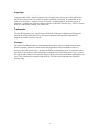
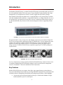
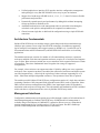
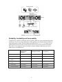
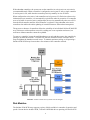
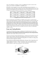
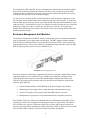
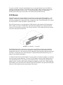
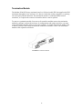
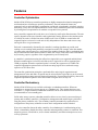
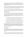
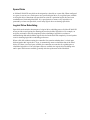
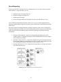
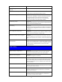
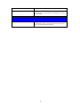
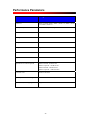
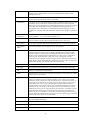
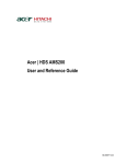
SANnet II 200 SCSI Array
Technical Product Description Guide
January 2003
83-00002947 Revision A
1
Copyright
Copyright 2001-2003 – Dot Hill Systems Corp. All rights reserved. No part of this publication
may be reproduced, stored in a retrieval system, translated, transcribed, or transmitted, in any
form or by any means – manual, electric, electronic, electromechanical, chemical, optical, or
otherwise – without prior explicit written permission of Dot Hill Systems Corp., 6305 El Camino
Real, P.O. Box 9000, Carlsbad, CA 92009-1606.
Trademarks
The Dot Hill Systems Corp. logo, SANnet, SANnet II, SANscape, SANpath and SANtrap are
trademarks of Dot Hill Systems Corp. All other trademarks and registered trademarks are
proprietary to their respective owners.
Changes
The material in this document is for information only and is subject to change without notice.
While reasonable efforts have been made in the preparation of this document to assure its
accuracy, Dot Hill Systems Corp., assumes no liability resulting from errors or omissions in this
document, or from the use of the information contained herein. Dot Hill Systems Corp., reserves
the right to make changes in the product design without reservation and without notification to its
users. This document was compiled and edited by Ted Uhler and Omar Barraza of Dot Hill
Systems Corp.
2
Contents
TABLE OF CONTENTS ............................................................................................................................. 3
INTRODUCTION ........................................................................................................................................ 4
KEY FEATURES ........................................................................................................................................... 4
ARCHITECTURE FUNDAMENTALS ................................................................................................................ 5
MANAGEMENT INTERFACES ........................................................................................................................ 5
RELIABILITY, AVAILABILITY AND SERVICEABILITY .................................................................................... 6
PERFORMANCE ............................................................................................................................................ 7
SCALABILITY ............................................................................................................................................... 7
ARCHITECTURE ....................................................................................................................................... 8
ENCLOSURE MODULES ................................................................................................................................ 8
CONTROLLER MODULES ............................................................................................................................. 8
DISK MODULES ........................................................................................................................................... 9
POWER AND COOLING MODULES .............................................................................................................. 10
ENCLOSURE MANAGEMENT UNIT MODULES ............................................................................................ 11
SCSI MODULE .......................................................................................................................................... 12
TERMINATION MODULE ............................................................................................................................ 13
FEATURES................................................................................................................................................. 14
CONTROLLER OPTIMIZATION .................................................................................................................... 14
CONTROLLER REDUNDANCY ..................................................................................................................... 14
CACHE PROTECTION.................................................................................................................................. 15
READ CACHING ......................................................................................................................................... 15
WRITE CACHING ....................................................................................................................................... 16
LOGICAL DRIVES ....................................................................................................................................... 16
DISK REDUNDANCY .................................................................................................................................. 16
SPARE DISKS ............................................................................................................................................. 17
LOGICAL DRIVE REBUILDING .................................................................................................................... 17
MANAGEMENT........................................................................................................................................ 18
CONFIGURATION ....................................................................................................................................... 18
MONITORING ............................................................................................................................................. 19
EVENT LOGS ............................................................................................................................................. 19
IN-BAND & OUT-OF-BAND MANAGEMENT ............................................................................................... 20
EVENT REPORTING .................................................................................................................................... 22
FIRMWARE UPDATES ................................................................................................................................. 23
RAID ........................................................................................................................................................ 24
CACHING ................................................................................................................................................... 24
ADVANCED FEATURES .............................................................................................................................. 25
RAID EXPANSION ..................................................................................................................................... 26
REDUNDANT CONTROLLERS ..................................................................................................................... 26
DATA SAFETY ........................................................................................................................................... 27
USER INTERFACE ....................................................................................................................................... 28
PERFORMANCE PARAMETERS.......................................................................................................... 29
DETAILED SPECIFICATIONS .............................................................................................................. 24
GLOSSARY ................................................................................................................................................ 30
3
Introduction
The SANnet II 200 SCSI array is a robust Ultra160 SCSI storage system and worthy successor to
the well-established SANnet 3300 series arrays. Fast performance, high availability and simple
manageability are condensed into a flexible, versatile, rugged and cost-effective package.
Each SANnet II 200 SCSI array holds twelve 1-inch high disks in a 2U package and is available
with dual redundant RAID controllers, a single RAID controller, or without controllers for use as
an expansion unit. An expansion unit can also be used as a stand-alone JBOD storage system or
as a host-based RAID array when used with volume management software supporting software
RAID.
FIGURE 1: Front View of a SANnet II 200 3310 SCSI Array (RAID, Expansion Unit/JBOD)
Designed to fulfill a variety of entry-level and midrange requirements, the SANnet II 200 SCSI
array is an excellent storage complement to many IT infrastructures. It can be supported by most
of today’s host platforms. And the SANnet II 200 SCSI array creates an application system
capable of serving a large number of users. For environments requiring very high levels of
storage capacity, a SANnet II 200 SCSI array expands to support up to 36 disks by adding two
expansion units.
FIGURE 2: Rear View of a SANnet II 200 SCSI Array
As a key component in a storage network, the SANnet II 200 SCSI array connects to host servers
via industry-standard Ultra160 SCSI host bus adapters, and to local and remote management
consoles via standard VT100 serial and Ethernet LAN connections.
Key Features
SANnet II 200 SCSI arrays are compact, ultra-dense, super-rugged storage systems that meet
entry-level and midrange requirements by providing affordable, enterprise-class performance and
availability features, management functionality and configuration flexibility. Some highlights:
·
An extremely space-efficient design provides up to 12 disks and redundant or single
RAID controllers in just 2U of rack space.
4
·
Unified graphical user interface (GUI) provides intuitive configuration, management
and reporting for every Dot Hill SANnet II series array in your environment.
·
Support for a broad range of RAID levels: 0, 1, 0+1, 3, 5, 3+0 and 5+0 assures flexible
performance and protection.
·
Dynamically expand capacity and performance by adding disks without interrupting
storage operations or attached servers.
·
Automated read and write cache management with user selectable write-through or
write-back cache policies and optimization for sequential or random access.
·
Choose between single-bus or dual-bus disk configurations using a simple SCSI cable
connection.
Architecture Fundamentals
SANnet II 200 SCSI arrays are modular storage systems that provide direct attached storage
(DAS) to open systems servers using Ultra160 SCSI connections. In addition to supporting
typical enterprise environments, these rugged systems are NEBS Level 3-certified for use in
telecommunications and ISP infrastructures, and Mil-STD-810F-certified for use in military
applications.
The modular architecture consists of a number of self-contained base enclosures, expansion
enclosures and disks. Each base and expansion enclosure occupies 2U of rack space and supports
up to 12 disks. Base enclosures include one or two controllers while expansion enclosures contain
no controllers. These three fundamental items fit together into a range of supported
configurations.
For example, a base enclosure can support more than 12 disks by adding one or two expansion
enclosures. Once expansion enclosures are added, the collection of enclosures and disks becomes
one fully integrated array – effectively the equivalent of a base enclosure supporting 24 or 36
disks – rather than multiple independent enclosures. The expansion of base units is optional.
The smallest possible SANnet II 200 SCSI array configuration consists of a single base enclosure
containing a number of fully integrated field replaceable units (FRUs) such as controllers. Other
FRUs include enclosure management units (EMUs), host input/output cards (SCSI modules),
termination cards and power/cooling units. The exact number and combination of FRUs included
within each base or expansion enclosure varies by SANnet II SCSI array model.
Management Interfaces
Configuration, administration and reporting are possible through a number of in-band and out-ofband management paths to SANnet II 200 SCSI arrays. SNMP-based LAN management is
available using a Fast Ethernet (10/100BASE-T) connection. Direct access to a menu-based
terminal management facility is within reach via VT100 serial ports. Dot Hill’s SANscape
provides remote management from administrator workstations.
5
FIGURE 3: Typical Sequence of Installation Steps
Reliability, Availability and Serviceability
Comprehensive reliability, availability and serviceability (RAS) are assured within SANnet II 200
SCSI arrays. Proven low voltage differential (LVD) signaling across all disk and host SCSI buses
keeps data transfers reliable. Flexible support for RAID levels 0, 1, 0+1, 3, 5, 3+0 and 5+0, plus
global and dedicated spare disks provide powerful choices for protecting valuable information.
Every FRU is hot-swappable or hot-serviceable to virtually eliminate downtime, plus critical
FRUs operate in redundant pairs.
Base Unit
with Redundant
Controllers
Base Unit
with Single Controller
Expansion Unit
(no controllers)
Controller Modules
Hot-swappable
Hot-serviceable
Not applicable
Disk Modules
Hot-swappable
Hot-swappable
Hot-swappable
Power and Cooling
Modules
Hot-swappable
Hot-swappable
Hot-swappable
Event Management
Modules
Hot-swappable
Hot-swappable
Not applicable
SCSI Modules
Hot-serviceable
Hot-serviceable
Hot-serviceable
Termination Modules
Hot-serviceable
Hot-serviceable
Not applicable
6
Performance
SANnet II 200 SCSI arrays provide very high levels of performance within a compact package.
The use of Ultra160 SCSI technology throughout for disks and servers results in performance
approaching that of storage area networks (SAN) from a direct attached storage (DAS) solution.
Cache memories of up to 1GB per array with support for 15,000RPM disks and flexible choices
of hardware-based RAID level protection ensure optimum performance.
Scalability
Room for 12 disks within an enclosure that occupies just 2U of rack space provides ample
capacity for many environments. A choice of 36GB, 73GB and 146GB disks permits users to
balance the number of disks and storage capacity needed. When even more storage capacity is
required, expansion enclosures can be added to expand the number of disks up to 24 or 36,
providing up to 5.25TB of total storage capacity in just 6U of rack space.
7
Architecture
SANnet II 200 SCSI arrays use modular design principles. Essentially, each array is a collection
of independent modules that operate cooperatively, providing all the necessary array functions.
The foundation of every array is the enclosure module.
Enclosure Modules
The primary building block of any SANnet II 200 SCSI array is its enclosure. It consists of a
compact metal chassis with internal controller mid-plane and disk mid-plane. The controller midplane interconnects the rear-facing FRUs and connects to the SCSI buses of the disk mid-plane.
The disk mid-plane provides the internal enclosure connections for the disks. The enclosure
securely holds and interconnects other FRUs to create a functional storage system.
The SCSI bus configuration for disks can be set to split-bus or single-bus using an external SCSI
cable connection. The default mode is for a split-bus disk configuration. Connecting the included
SCSI bus configuration cable joins the split-buses into a single-bus configuration and changes the
SCSI ID settings of the disks shown on the label on the front of the enclosure. Use of the split-bus
option requires that two separate controller SCSI buses are available for disk use.
The enclosure itself is a FRU with no serviceable components. If the chassis or an internal midplane were damaged, all of the other FRUs could be removed and inserted into a replacement
enclosure in minutes. There are no critical active components within the chassis or on the internal
mid-planes, so the chance of a component failure within an enclosure is very low.
The base and expansion enclosures of SANnet II 200 SCSI arrays appear similar, but they are not
interchangeable. It is not possible to convert an expansion enclosure to a base enclosure, or vice
versa. The base enclosure and expansion enclosure FRUs are different and unique.
Controller Modules
The SANnet II 200 SCSI array is available with either single or redundant controllers. Each
controller has four Ultra160 SCSI channels and 512MB of cache that is battery protected for 72
hours during a power failure. Intelligent caching algorithms and support for RAID levels 0, 1,
0+1, 3, 5, 3+0 and 5+0 provide extensive performance and protection. Support for up to 128
LUNs per array ensures flexibility and simplified configuration.
FIGURE 4: Module Locations (rear panel)
The SCSI channels of SANnet II 200 SCSI array controllers can be configured for use with disks
or hosts. At least one SCSI channel must be configured for disks and another SCSI channel for
hosts. The remaining two SCSI channels can be configured for use with disks or hosts as
required.
8
With redundant controllers, the system can use the controllers in active/passive or active/active
(recommended) mode. When a controller is configured as active/passive, only a single controller
is used to process I/O, while the other controller passively stands by in case of failure.
When configured as active/active, both controllers actively process I/O. Each time a host writes
information to one controller, it is automatically copied to the other for protection. If a controller
were to fail while in an active/active configuration, the survivor automatically takes over all I/O
from the failed controller until the failed controller is replaced. Using redundant active/active
controllers also enables the online updating of controller firmware without host interruptions.
The presence or absence of controllers affects the scalability of an individual SANnet II 200 SCSI
array. Enclosures with controllers can scale by adding one or two expansion enclosures, but
enclosures without controllers cannot be expanded.
To remove a controller, loosen the small thumbscrews at each end then remove the controller by
pulling it out from the enclosure. To install one, slide the controller into the enclosure until it
stops and tighten the thumbscrew until secure. To maintain optimum cooling, avoid operating a
SANnet II 200 SCSI array for more than a few minutes with a controller removed.
FIGURE 5: SANnet II 200 SCSI Array RAID Controller Diagram
Disk Modules
The SANnet II 200 SCSI array supports a variety of disks available in a number of capacities and
speeds. Current choices include 36GB, 73GB and 146GB disk drives operating in Ultra160 SCSI
9
mode. The 146GB disk is available in speeds of 10,000RPM only at this time, but the other
capacities are available in 10,000RPM or 15,000RPM speeds.
Disks FRUs are hot-swappable or hot-serviceable depending their logical configuration – i.e.,
depending on whether the disks are configured to provide redundant RAID protection or not. The
disks are not slot dependent. This allows them to be removed, stored and replaced into the system
in random order without affecting stored information or system configuration.
FIGURE 6: Disk Drives (front view with bezel removed)
Disks are mounted into a rugged sliding tray and held securely in place by a front-mounted
handle with locking thumbscrew. To remove a disk, turn the thumbscrew collar on its front panel
to the left until loose, then lift the handle and pull the disk tray out of its slot. To install a disk,
slide the disk into an empty slot until it stops, lower the handle fully and turn the thumbscrew to
the right until secure. To lock a disk in place, use a Phillips screwdriver to turn the screw within
the thumbscrew collar to the right. To unlock a disk, turn the screw to the left. Avoid operating a
SANnet II 200 SCSI array for more than a few minutes with a disk removed to maintain optimum
cooling. If a disk is being removed for an extended period of time, install an air management
module in its place.
Power and Cooling Modules
The SANnet II 200 SCSI array features a redundant pair of combination power and cooling
modules. Each is a fully integrated FRU that includes an isolated power inlet, a 420-watt power
supply and dual 52CFM cooling fans. Each FRU can provide the power and cooling necessary to
operate the entire enclosure in the event one were to fail.
The power and cooling of SANnet II 200 SCSI arrays is designed for maximum RAS. The power
supplies support automatic load sharing and load balancing to ensure long service lives. Power
supplies are further protected from the potential damage due to over-current, over-voltage, short
circuits and extreme temperature conditions.
Power options are available to support worldwide AC or DC power. The AC option has an autoranging capability from 90VAC to 264VAC and 47Hz to 63Hz. The DC option has an autoranging capability of –36VDC to –72VDC. An enclosure can be converted from one power
option to another by simply replacing both power and cooling FRUs.
FIGURE 7: Power/Cooling Module
10
The cooling fans within each FRU operate as matched pairs with tachometer-controlled spindles
and position-synchronized blades for maximum efficiency. Every cooling fan operates from a
common power bus so the failure of a power supply will not interrupt the operation of any fans,
even those in the same FRU as the failed power supply.
To remove a power/cooling module, turn the thumbscrew collar at the upper right corner to the
left until loose then lower the handle down and pull the FRU out of the enclosure. To install one,
slide the FRU into the enclosure until it stops, lift the handle fully and turn the thumbscrew to the
right until secure. To lock an FRU in place, use a Phillips screwdriver to turn the screw within the
thumbscrew collar to the right. To unlock one, turn the screw to the left. Avoid operating a
SANnet II 200 SCSI array for more than a few minutes with a power/cooling module removed to
maintain optimum cooling.
Enclosure Management Unit Modules
The enclosure management unit (EMU) controls, monitors and reports environmental parameters
such as temperature, power supply status and fan speed. The EMU supports industry standard
SAF-TE protocols and features three micro-controllers that supervise FRU control, monitoring
and reporting functions. These micro-controllers communicate among themselves and with other
FRUs using a proprietary protocol across a standard I2C bus.
FIGURE 8: Enclosure Management Unit
One micro-controller is dedicated to communications between controllers and the EMUs using a
proprietary protocol across a standard I2C bus. Another micro-controller is dedicated to the
reporting of FRU status using the various FRU-mounted light emitting diode (LED) visual
indicators. The primary micro-controller supervises the other micro-controllers and performs
numerous other functions:
·
Communications with the serial EEPROM on the disk mid-plane when needed.
·
Monitoring of power supply status, cooling fan status and temperature sensors.
·
Control of front-panel system status LEDs and audible alarm reset switch.
·
Management of a proprietary serial communication link to expansion enclosures.
Each SANnet II 200 array contains two redundant Enclosure Management Unit (EMU), FRUs
operating in a master-slave configuration with automated fail-over and fail-back. The master is
active and the slave is passive. If the master EMU fails, the slave EMU begins to provide all
necessary functions without interruptions until the failed master EMU is replaced. If a slave EMU
fails, the master EMU continues to provide all functions without interruptions.
11
To remove an EMU, loosen the small thumbscrews at each end and then remove the EMU by
pulling it out from the enclosure. To install one, slide the EMU into the enclosure until it stops
and tighten the thumbscrew until secure. To maintain optimum cooling, avoid operating a
SANnet II 200 SCSI array for more than a few minutes with an EMU removed.
SCSI Module
The SCSI connections to hosts and between enclosures are made at the SCSI modules (i.e., I/O
modules). This hot-serviceable module is used to select between split-bus and single-bus disk
mid-plane configurations using the SCSI bus configuration cable. The SCSI modules also contain
the actual SAF-TE circuitry the EMUs communicate with.
Each SCSI port features a very high-density (VHD) interface with automatic SCSI termination,
where needed. To remove a SCSI module, loosen the large thumbscrews at each end and then
remove the SCSI module by pulling it out from the enclosure. SCSI modules differ between base
enclosures and expansion enclosures.
FIGURE 9: SCSI Module (i.e., I/O Module)
The SCSI channels of base enclosures can be set for use with disks or hosts by the controllers,
and expansion enclosures can be used as stand-alone storage systems with host-based volume
management software, so the numerous possible methods of connecting hosts and interconnecting
enclosures is beyond the scope of this document. Consult the SANnet II 200 SCSI array user’s
guide for more detailed information.
A SANnet II 200 SCSI array SCSI module is hot-serviceable, but not hot-swappable, so replacing
one will require planned downtime. To remove a SCSI module, loosen the large thumbscrews at
each end and then remove it by pulling it out from the enclosure. To install one, slide the SCSI
module into the enclosure until it stops and tighten the thumbscrew until secure. When replacing
SCSI modules, move the SCSI cables from the original SCSI module to the equivalent SCSI ports
of the new SCSI module after the replacement for best results.
12
Termination Module
The SANnet II 200 SCSI array terminator board is a field-serviceable FRU that supplies the SCSI
termination throughout a base enclosure. It is hot-serviceable but not hot-swappable, so replacing
one will require planned downtime. The termination module is essentially hidden between
controllers, so it requires the removal of controllers before it can be replaced.
To remove a termination module, first remove all controllers and then remove the termination
module by pulling it out from the enclosure. In configurations with single controllers, you must
remove the blank controller panel as well as the controller. To install a termination module, slide
it into the enclosure until it stops. Reinstall the controllers when done. There is no termination
module within expansion enclosures.
FIGURE 10: Termination Module
13
Features
Controller Optimization
SANnet II 200 SCSI array controller operations are highly automated to minimize management
workloads and are self-tuning to optimize performance. Powerful advanced features are
supported, such as multi-threading, segmentation, read-ahead, write-through, write-back, queuing
and sorting. Array users can adjust controllers to more closely match their particular environment
by selecting between optimization for random or sequential access patterns.
Array controllers segment their cache into a set of relatively small cache allocation units. The unit
capacity depends on the user-selectable cache optimization setting. Whenever the random option
is selected, the cache is divided into units of 4KB each. Units of 16KB are created when the
sequential option is selected. A cache unit is fully independent of the others and can serve any
one logical drive at a given moment.
Each unit is automatically allocated by the controller’s caching algorithms to provide read
caching or write caching and dynamically reassigned as needed. For example, when the number
of vacant cache units becomes low, write-back units might be flushed to disks or read-ahead units
may be unallocated to make them available for other uses. Empty cache units can be allocated for
any necessary purpose, regardless of the assignment they most recently held.
A controller’s optimization setting also affects how logical drives are organized and initialized.
When the random option is selected, each disk used in a logical drive will be segmented into
32KB per segment. When the sequential option is selected, the segment size is 128KB. The
sequential optimization option must be used when creating logical drives with total storage
capacities of 512GB or more.
The controller optimization setting has a profound effect on the logical organization and
management of cache and disks. An option must be selected before logical drives can be created,
but the optimization setting cannot be changed dynamically. For maximum flexibility, choose the
sequential optimization option to allow the creation of logical drives of any size.
Controller Redundancy
SANnet II 200 SCSI arrays are available with single or redundant controllers. When two
controllers are present, they always operate as a redundant pair. They cannot function as two
individual, i.e., single controllers. Redundant controllers can be set to function in active/active
(recommended) or active/standby pairs.
Unlike other storage systems, redundant controllers behave as one virtual system consisting of
primary and secondary controllers. Configuration, management and monitoring are performed
using the primary controller only. The secondary controller automatically synchronizes its
configuration to the primary controller to ensure their configuration remains identical.
If an active controller detects the other controller of a redundant pair is malfunctioning or has
failed, it immediately disables the faulty controller and transparently resumes its workload. This
temporary process, called failover, occurs almost immediately and without interuption to server
or array operations.
14
The surviing controller of a fail-over process always becomes the primary controller. Replacing
the faulty controller will result in an automatic fail-back process, where the array restores a
redundant controller configuration. The new controller will become the secondary controller until
the next reset or power cycle of the array, at which time the original primary/secondary
arrangement will be restored.
A particular logical drive must be assigned to either the primary or secondary controller. The
controller a logical drive is assigned to performs all necessary functions for that set of disks until
a controller fail over occurs. One logical drive cannot be assigned to both controllers, but logical
drives can be distributed among the controllers to balance controller workloads.
It is necessary to connect management interfaces to both redundant controllers. For example, if
one controller is connected to a management network, the second controller should be also be
connected. Failure to do this may interupt management access if a controller fail over occurs.
Cache Protection
The controllers of SANnet II 200 SCSI arrays contain specialized memory designed to enhance
performance through caching. Array controllers use this high-speed cache to provide better
response times, transaction rates and transfer rates than is possible from array disks alone. The
contents of the cache must be protected against loss since information flows through it while
disks in the array are being read from or written to. SANnet II 200 SCSI arrays protect its cache
in a number of proven ways:
·
Each controller contains a battery backup that continually protects cache content from
loss for 72 hours due to uncontrolled shut downs or unplanned power loss.
·
Arrays with redundant controllers synchronize write cache content between controllers
to ensure the information remains available in the event of controller fail over.
·
Write-back cache contents are transparently written to the appropriate disks during
periods of low controller activity and as the write cache reaches maximum capacity.
·
Controllers minimize the amount of time information remains within write-back cache
and will flush the information to disks after several seconds regardless of activity.
If an uncontrolled shut down or power loss occurs, the battery backups preserve the entire
contents of the controller cache memories for 72 hours. If the SANnet II 200 SCSI array is
powered on within this time frame, the controllers automatically flush any necessary information
to disks during start up. After 72 hours, the battery backups will discharge completely and all
information within the cache will be permanently lost – which will result in limited data loss
when write-back caching is enabled.
Read Caching
SANnet II 200 SCSI arrays continually use read caching to maximize performance. Any recent
information read from an array remains in its controller cache memory to improve response times
and to reduce disk activity if the same information is requested again. Older information is
automatically replaced with newer information as the amount of allocated read cache memory
begins to fill.
Whenever a controller detects three sequential read requests for information, the controller
automatically begins reading-ahead to reduce the latency of subsequent read requests to maximize
transfer rates. The controller will continue read-ahead operations until the current allocated
15
amount of read cache memory is filled or sequential requests are no longer detected. If available
read cache memory fills and sequential read requests continue, the controller will flush write
cache content and allocate additional memory to read operations automatically.
Since read cache contents are identical to information already on disks, read cache memory is
never synchronized between redundant controllers. Reducing cache synchronization activity
minimizes controller workloads and ensures extremely efficient utilization of cache memory.
Write Caching
SANnet II 200 SCSI arrays provide important safeguards for stored information. One option that
has an effect on how information is protected is user-selectable write-through (safest) or writeback (fastest) caching. Neither write-cache option is superior in every environment, so it is
important to understand what each option does before choosing.
With write-through caching selected, all information received by a SANnet II 200 SCSI array is
written to its disks before the array confirms the successful completion of the write operation.
Information is always written to disks when using write-though caching so write information
never remains within the controller’s cache, but write performance is limited by the speed of the
disks.
Write-back caching changes write behavior to enhance performance without compromising
protection. It allows an array to confirm successful completion of write operations when
information reaches cache rather than disks. Controllers contain battery backups that protect the
content of cache memories for up to 72 hours. When redundant controllers are present and
operating in active/active mode, write-back cache contents are continually synchronized between
controllers for added protection. Cache operates at speeds orders of magnitude faster than disks,
so write-back caching often provides significant performance improvement.
Choosing write-cache modes is often based on the number of controllers present within a SANnet
II 200 SCSI array. When using an array with a single controller, write-through caching protects
against potential data loss that could occur if the controller failed while using write-back caching.
A controller will not represent a single point-of-failure in an array with dual controllers (i.e., with
redundant controllers or N+1), so write-back caching often provides the best results.
Logical Drives
A logical drive is a set of drives grouped together to operate under a particular RAID level. Each
array is capable of supporting as many as eight logical drives, and a logical drive can be further
divided into a maximum of 32 partitions. The logical drives can have the same or different RAID
levels. The total number of partitions cannot exceed 128 partitions per array. If you want to assign
128 partitions to 128 LUNs in an array, you need to have a minimum of four logical drives with
32 partitions each.
Disk Redundancy
As with most arrays, disk redundancy is provided by the RAID features supported by SANnet II
200 SCSI arrays. Configuring a set of disks into a logical drive operating under a mirrored or
parity-protected RAID level ensures information will not be lost in the event of a disk failure.
Moreover, taking advantage of the spare disk capabilities of SANnet II 200 SCSI arrays further
enhances disk redundancy.
16
Spare Disks
A SANnet II 200 SCSI array disk can be assigned as a data disk or a spare disk. When configured
as a spare, it can serve as a local spare to one specified logical drive or as a global spare available
to all logical drives. More than one spare disk can exist for a particular logical drive and even
combinations of local and global disks. It is a good practice to ensure every logical drive is
protected by at least one spare disk, even if many logical drives are sharing spare disks.
Logical Drive Rebuilding
Spare disks are destined to become part of a logical drive rebuilding process. SANnet II 200 SCSI
arrays provide several options for detecting the need to rebuild a logical drive. For example, an
array may wait until a disk fails completely before rebuilding a logical drive or detect a
malfunctioning disk and rebuild the logical drive before the disk fails completely. Several options
exist for choosing logical drive rebuilding preferences.
When a disk fails without warning, the controller first examines whether there is a local spare
disk assigned to this logical drive. If yes, it automatically starts to rebuild the data of the failed
disk to it. If there is no local spare available, the controller next searches for a global spare to
rebuild the logical drive. If no valid spare disks are available, the logical drive rebuilding waits
until a spare disk becomes available, generally after the replacement of the failed disk.
17
Management
Configuration
Dot Hill’s SANscape software is a Java technology-based software program that combines
storage configuration, maintenance and monitoring tools into a single, easy-to-use package.
SANscape software provides centralized administration of SANnet II 200 SCSI storage systems
across existing local and wide area networks (WANs). It greatly simplifies storage management
and reduces its administration costs.
The SANscape software graphical interface uses intuitive controls and graphics to present
configuration options, maintenance features and status information for storage systems and
servers. A color-coded design provides feedback and clear status information for each
component. Critical conditions that require immediate attention are always easily identified and
simple to locate. Configuration features and controls are well marked and operate smoothly.
SANscape software is also very easy to learn through its use of familiar interface elements.
SANscape software provides complete monitoring of SANnet II 200 specific RAID controllers,
disk drives, etc. From a single SANscape console located anywhere on a network, system
administrators can view entire SANnet II 200 storage systems, change storage configurations and
monitor storage status. In the event of a status change, Dot Hill’s SANscape software sends realtime, proactive alerts to the system administrator via its console display, e-mail, or through an
alphanumeric pager, allowing users to monitor the storage system remotely.
Storage setup and management is easy with SANscape software. Custom configuration options
allow network administrators to configure storage volumes, RAID levels, cache modes, stripe
sizes and other storage parameters to meet particular server and application requirements.
SANscape also allows dynamic array firmware upgrades when there are dual redundant
controllers configured. With SANscape's unsurpassed ease of use and attention to detail, even the
most ambitious storage installations are simple to manage.
FIGURE 11: SANscape Menu Options
18
Monitoring
The main SANscape window provides status at a glance for all networked array devices. It
indicates the status of the devices and logical drives connected to servers monitored by the
SANscape Console. The devices include host adapters, array controllers, disk storage enclosures,
physical disk drives and other SCSI devices.
The window’s tree structure offers detail for all devices connected to each server. The container
symbol at the left side of the tree indicates whether the display of devices is expanded or
collapsed. The container symbol means that you can click to display more devices. The container
symbol indicates that all devices at and below that level are shown.
FIGURE 12: Main SANscape Window
Event Logs
The SANscape console receives, logs and displays events generated by managed servers and by
the SANscape console itself. Most events are generated by the SANscape Agents on the managed
servers and occur when there are:
·
Status changes on any device on a managed server, including the server itself
·
Inventory changes such as the addition or removal of devices
·
Configuration changes including initial configuration setup and subsequent changes
·
Array processes running such as initialization, parity checking and rebuilding
Although the SANscape console initiates array processes, it is the server agent that generates
operation notification events after these processes start on the server. The SANscape console
generates a much smaller number of events. For example, it generates an event if it does not
receive a certain number of consecutive heartbeats from a managed server.
19
When the console receives any event, it logs it into SANscape’s Event Log file,
EVENTLOG.TXT, and displays it in the Event Log window. Also, if the event occurs on a
server, the notification of the event is sent to that server’s operating environment/system event
log. On an NT server, it would go to the NT event log. In addition, when the event occurs on a
server and that server is set up to send traps to an SNMP enterprise management console, such as
HP OpenView, the server agent also sends a trap message to that computer.
Depending on the event received, the console might initiate a refresh process to request the
inventory from the last periodic scan of the server involved, so the console can update the
server’s inventory on the main SANscape window.
During this refresh process, the satellite dish icon is attached to the server icon, and you cannot
perform any SANscape configuration and array activity commands on that server until the
process is completed and the main window is updated.
SANscape’s Event Log window displays up to 500 events at a time. If you have more than 500
events, only the most recent 500 are displayed in the Event Log window; however, SANscape
does not delete any events from the Event Log file, EVENTLOG.TXT, until more than 10,000
events have been logged.
·
After 10,000 events, SANscape reduces the Event Log file to the most current 500
events and then accumulates events until the limit of 10,000 is exceeded again.
·
A semi-colon separates the fields of each event record so you can easily import the file
into a database.
·
EVENTLOG.TXT is located in the directory where the SANscape console program
files are installed.
FIGURE 13: Event Log Window
20
In-Band & Out-of-Band Management
SANscape’s out-of-band storage management capability enables you to monitor and manage Dot
Hill arrays over the network using TCP/IP. Unlike in-band storage management (the standard
method of storage management for storage), which requires the SANscape Agent to be running
on the server that is physically attached to the storage, out-of-band storage management does not
require the SANscape Agent to be running on the server that is physically attached to the storage.
With out-of-band storage management, you do not need to load extra software on the server, and
you have the flexibility to monitor and manage storage from anywhere on the network.
FIGURE 14: In-Band Management
FIGURE 15: Out-of-Band Management
21
Event Reporting
You can use Dot Hill’s SANscape to run as a background service to report events to specified
email addresses. Using SANscape, you can:
·
Define the types of message traps sent
·
Define the timing of messages sent
·
Send encrypted messages
·
Receive messages and decrypt encrypted messages on the Mail Receiver Tool
To use SANscape throughout the network, install it as a service on each computer that has a
SANscape agent running (an agent is the software that communicates to attached SANnet II 200
SCSI arrays).
One major benefit of installing SANscape on all host computers is that it can be configured to
ping each computer periodically, and to send a single-point-of-failure message from a SANscape
agent to the specified email addresses when a host fails. SANscape includes the following
components:
·
SANscape Agent (daemon) – operates in background mode continuously on the
computer where it is installed. The daemon can be installed and used on any computer
where SANscape is running.
·
SANscape Config Tool (UI) – a utility that configures the types of message traps that
are sent to the SANscape Agent and that are sent to a specific email address as an alert
or for informational purposes. Also known as the user interface (UI).
·
SANscape Mail Receiver Tool – displays the messages that are collected. Also known
as the POP3 Mail Receiver.
FIGURE 16: Typical Diagnostic Service and SANscape Setup
22
Firmware Updates
Fast and easy download of new versions of controller and disk firmware is possible using the
SANnet II 200 SCSI array management suite. The Dot Hill CLI and SANscape both support
controller updates over in-band SCSI connections and out-of-band Ethernet connections.
SANscape provides updates for disks over in-band SCSI connections.
When firmware updating is performed on a redundant controller array, firmware is loaded onto
both controllers without interrupting operations. When the download process is complete, the
primary controller will reset and let the secondary controller take over all services temporarily.
When the primary controller comes back on-line, the secondary controller will transfer over all
operations and reset. Once the secondary controller comes back online, the primary controller
restores the redundant controller configuration. The redundant controllers automatically perform
the upgrade process.
A controller that replaces a failed unit in a dual-controller system might be running a different
release of firmware version. To eliminate the potential for issues, the existing array controller
automatically updates the firmware of the replacement controller to match the existing
controller’s firmware.
23
Detailed Specifications
RAID
RAID levels
0, 1, 0+1, 3, 5, 1+0, 3+0 and 5+0. Enhanced RAID Levels
supported with logical volume implementation.
Maximum number of logical drives
8
RAID level dependency to each logical
drive
Independent. Logical drive configured in different RAID levels
can co-exist in an array
Maximum number of drives for each logical
drive
31 (RAID 3 or 5); 45 (RAID 0 or NRAID); 44 (RAID 0+1)
Logical drive identification
Unique, controller randomly generated logical drive ID; Logical
drive name user-configurable
Maximum partitions of each logical drive
32
Maximum number of logical drives in a
logical volume
8
Maximum number of logical volumes
8
Maximum number of LUN per host ID
Up to 32, user configurable
Concurrent I/O
Supported
Tag command queuing
Supported
Dedicated spare drive
Supported
Global spare drive
Supported
Co-existing dedicated and global spare
drives
Supported
Auto-rebuild onto spare drive
Supported
Auto-scan of replacement drive upon
manually initiated rebuild
Supported
Auto-rebuild onto failed drive replacement
Supported. With no spare drive assigned, the controller will autoscan the failed drive and starts to rebuild automatically once the
failed drive has been replaced.
Background firmware download
Firmware can be downloaded during active I/Os. Administrator
may find appropriate time to reset controller later.
Auto recovery from logical drive failure
Supported.
Caused when a user accidentally removes the wrong disk and
causes a 2nd disk failure of a logical drive with one previously
failed disk
Caching
Write-back cache
Supported
Write-through cache
Supported
24
Supported memory type
SDRAM memory for enhanced performance. Fast page memory
with parity for enhanced data security. ECC-protected.
Read-ahead operation
Intelligent dynamic read-ahead operation for sequential data
accessing
Multi-threaded operation
Yes
Scatter/gather supported
Supported
I/O sorting
Supported. Optimized I/O sorting for enhanced performance
Variable stripe size
RAID5:
Optimization for random I/O (32k), optimization for sequential
I/O (128k), user selectable.
RAID3:
Optimization for random I/O (4k), optimization for sequential I/O
(16k), user selectable.
Advanced Features
Drive low-level format
Supported
Drive identification
Supported
Force the drive to light on the activity indicator for user to
recognize the correct drive.
Drive information listing
Supported
Drive vendor name, model number, firmware revision, capacity
(blocks), serial number, narrow/wide negotiations and current
SCSI speed.
Drive read/write testing
Supported
Configuration on disk
Supported
The logical drive information is recorded on drive media.
Save/restore NVRAM to/from disks
Supported
Save all the settings stored in the controller NVRAM to the logical
drive members
Save/restore NVRAM to/from file
Supported
Save all the settings stored in the controller NVRAM to a file via
GUI or CLI on user’s computer
Host LUN geometry & user configurable
default geometry
Capacity <64GB: Head=63, Sector=32, Cylinder=?
(depends on capacity)
64GB<capacity<128GB:Head=64, Sector=64, Cylinder=?
(depends on capacity)
128GB<capacity<256GB: Head=127, Sector=64, Cylinder=?
(depends on capacity)
256GB<capacity<512GB: Head=127, Sector=127, Cylinder=?
(depends on capacity)
512GB<capacity<1TB: Head=255, Sector=64, Cylinder=?
(depends on capacity)
1TB<capacity: Head=225, Sector=225, Cylinder=?
(depends on capacity)
User configurable geometry range
Sector: 32,64,127,255 or variable
25
Head: 64,127,255 or variable
Cylinder: <1024, <32784,<65536 or variable
Drive motor spin-up
Supported
The controller will send spin-up (start unit) command to each
drive at 4 sec. intervals.
Drive-side tag command queue
Supported
User adjustable up to 128 for each drive
Host-side maximum queued I/O count
Supported
User adjustable up to 1024
Maximum concurrent host LUN connection
Supported
User adjustable up to 64
Number of tags reserved for each host LUN
connection
Supported
User adjustable up to 256
Drive I/O timeout
Supported
User adjustable
RAID Expansion
On-line RAID expansion
Supported
Mode-1 RAID expansion-add drive
Supported
Multiple drives can be added concurrently.
Mode-2 RAID expansion – copy and
replace drives
Supported
Replace members with drives of larger capacity.
Expand capacity with no extra drive bays
required
Supported in Mode 2 RAID expansion. Provide “Copy and
Replace Drive” function to replace drives with drives of greater
capacity. No need to add another enclosure for the extra drives.
Operating environment support for RAID
expansion
No operating environment driver required. No software has to be
installed for this purpose.
Redundant Controllers
Active-active redundant controller
Supported
Synchronized cache for both controllers
Supported
Through a dedicated synchronizing channel, synchronized cache
over Fibre loops is supported.
Write-back cache enabled in redundant
controller mode
Supported
Using synchronized cache connection between controllers.
Automatic failover
Supported
Automatic failback
Supported
Controller hot-swap
Supported
Support on-line hot-swap of the failed controller. There is no need
to reset or shutdown the failed controller. One redundant
controller can be pulled out during use.
Redundant controller communication
channel
RAID: SCSI; RCC Reset signals built-in
26
No single-point-of-failure
Supported
Automatic engagement of replacement
controller
Supported
Dynamic cache memory allocation
Supported
Cache memory is dynamically allocated, not fixed.
Environment management
Supported
SAF-TE, S.E.S., ISEMS (I2C interface), and onboard controller
voltage/temp monitor are all supported in both single and
redundant controller mode. In the event of controller failure,
services can be taken over by the existing controller.
Cache battery backup
Supported
Battery backup solutions for cache memory are supported in both
single controller and redundant modes.
Load sharing
Supported
Workload can be flexibly divided between different controllers by
assigning logical configurations of drives (LDs/LVs) to different
controllers.
User-configurable channel mode
Supported
Channel modes configurable (SCSI) as HOST or DRIVE in both
single controller and redundant controller mode.
Redundant controller firmware upgrades
Supported
Firmware upgrade can be downloaded to the primary controller
and then be adopted by both controllers, without interrupting host
I/O.
Redundant controller firmware
synchronization
Supported
In the event of controller failure, a replacement controller running
a different version of firmware can restore a redundant array with
a failed controller. Different firmware versions can be autosynchronized later.
Data Safety
Regenerate parity of logical drives
Supported
Can be performed periodically by the user to ensure that bad
sectors do not cause data loss in the event of drive failure.
Bad block auto-reassignment
Supported
Automatic reassignment of bad block
Battery backup for cache memory
Supported
The battery backup solutions provide long-lasting battery support
to the cache memory when power failure occurs. The unwritten
data in the cache memory can be committed to drive media when
power is restored.
Verification on normal writes
Supported
Performs read-after-write during normal write processes to ensure
data is properly written to drives.
Verification on rebuild writes
Supported
Performs read-after-write during rebuild write to ensure data is
properly written to drives.
Verification on LD initialization writes
Supported
Performs read-after-write during logical drive initialization to
ensure data is properly written to drives.
27
Drive S.M.A.R.T. support
Supported
Clone failing drive
Supported
Users may choose to clone data from a failing drive to a backup
drive manually
User Interface
RS-232C terminal
Supported
terminal modes: ANSI, VT-100, ANSI Color. Provides menudriven user-friendly text-based interface.
28
Performance Parameters
Parameter
Range
RAID level
JBOD, N-RAID, RAID 0, RAID 1, RAID 1+0, RAID 3, RAID
3+0, RAID 5, RAID 5+0
Rebuild priority
Low, Normal, Improved, High
Verification on write
Enabled or disabled
Max tag count
1-128 or disabled
Max queued I/O count
32-1024 or auto
LUNs per SCSI ID
Up to 32
Number of host-LUN connections
1-64
Tag per host-LUN connection
1-256
Optimization for random/sequential
RAID 3 Random - 4K Block Size
RAID 3 Sequential - 16K Block Size
RAID 5 Random - 32K Block Size
RAID 5 Sequential - 128K Block Size
Write-back cache
Enabled or disabled
Optional paired controller configuration
Active/active or active/standby
Cylinder, head, sector mapping
Supported
29
Glossary
active termination,
regulated
Terminates the SCSI bus with a series of resistors tied to +5 volts. The terminator is
labeled Regulated but is often referred to as an Active Terminator.
active-active
controllers
A pair of components, such as storage controllers in a failure-tolerant RAID array that
share a task or set of tasks when both are functioning normally. When one component of
the pair fails, the other takes the entire load. Dual active controllers (also called dualactive controllers) are connected to the same set of devices and provide a combination of
higher I/O performance and greater failure tolerance than a single controller.
ANSI
American National Standards Institute
automatic rebuild
A process where data is automatically reconstructed after a drive failure and written to a
standby (spare) drive. An automatic rebuild will also occur when a new drive is installed
manually in place of a failed drive. If the rebuild process is interrupted by a reset, use the
Rebuild command on the Array Administration menu to restart the rebuilding process.
background rate
The background rate is the percentage of available array controller CPU time assigned to
array administration activities, such as rebuilding failed drives, checking parity, and
initialization. If the background rate is set to 100%, the array administration activities
have a higher priority than any other array activity. At 0%, the array administration
activity is done only if there is no other activity on the array controller.
bandwidth
A measure of the capacity of a communication channel, usually specified in MB/second.
cache
Memory on the RAID controller card, which permits intermediate storage of, read and
write data without physically reading/writing from/to the disk, which can increase overall
performance under certain conditions.
caching
Allows data to be stored in a pre-designated area of a disk or RAM (random access
memory). Caching is used to speed up the operation of RAID arrays, disk drives,
computers and servers, or other peripheral devices.
CH
Channel
channel
Any path used for the transfer of data and control information between storage devices
and a storage controller or I/O adapter. Also refers to one SCSI bus on a disk array
controller. Each disk array controller provides at least one channel.
CISPR
International Special Committee on Radio Interference
CLI
Command line interface.
concatenated
channel
Inside the same drive array enclosure, a single contiguous drive channel supporting 12
drives concurrently
device name
Software device address that identifies the controller/LUN, such as cXtYdZs0, where X is
the host bus adapter, Y is the controller, and Z is the LUN. s0 slice number is used by the
system, not by RAID Manager.
disk array
Two or more drives configured as a Drive Group (see next).
drive group
A physical set of drives configured as an array. Drive groups are defined during
configuration.
EMU
Event Monitoring Unit
expansion drive
array
An enclosure containing a group of drives, power supplies, cooling fans, I/O cards, and
mid-planes (no RAID controller/controllers); generally, an external drive array that is used
to daisy chain to an existing hardware based RAID configuration.
failover
A mode of operation for failure-tolerant arrays in which a component has failed and its
function has been assumed by a redundant component.
30
fast write
Allows disk write commands to be safely acknowledged to the host before the data is
actually written to the disk media. This can be enabled/disabled through the storage
management software.
fast/wide SCSI
Data transfer rate of 20 MB/sec. Wide devices can be connected to a standard SCSI
interface but the extra data lines need to be terminated.
fault tolerance
The capacity to cope with internal hardware problems without interrupting the array's data
availability, often by using backup systems brought online when a failure is detected.
Many arrays provide fault tolerance by using RAID architecture to give protection against
loss of data when a single disk drive fails. Using RAID 1 (mirroring), RAID 3 or 5
(striping with parity), or RAID 6 or 1+0 (mirroring and striping) techniques, the array
controller can reconstruct data from a failed drive and write it to a standby or replacement
drive.
fault tolerant
logical drive
A logical drive that provides protection of data in the event of a single drive failure by
employing RAID 1, 3, 5, or 6 (also known as RAID 1+0).
FC-AL
Fibre Channel-Arbitrated Loop. FC-AL is implemented as either a loop or a Fabric. A
loop can contain up to 126 nodes, accessible through only one or two servers.
fibre channel
A cost-effective gigabit communications link deployed across a wide range of hardware.
fibre channel
HBAs
Fibre channel adapters of a host computer, server, or workstation.
fibre hubs
An Arbitrated Loop Hub is a wiring concentrator. "Arbitrated" means that all nodes
communicating over this Fibre loop are sharing a 100MBps segment. Whenever more
devices are added to a single segment, the bandwidth available to each node is further
divided. A loop configuration allows different devices in the loop to be configured in a
token ring style. With a Fibre Hub, a Fibre loop can be re-arranged in a star-like
configuration for the Hub itself contains port bypass circuitry that forms an internal loop
inside. Bypass circuits can automatically reconfigure the loop once a device is removed or
added without disrupting the physical connection to other devices.
FRU
Field-Replaceable Unit
full-duplex
Data transmission in both directions at the same time. See also half-duplex and simplex.
GB
Gigabyte. 1,000,000,000 (one billion) bytes.
GBIC
Gigabit Interface Converter. A hot-swappable input/output device that plugs into a Gigabit
Ethernet port or Fibre Channel.
groups
A group is a new data object that allows multiple servers to be contained under a single
category, are similar in concept to domains, and allow you to organize servers within
SANscape. Instead of a linear tree of all the managed servers, the SANscape operator can
organize the servers into like sets or groups. In the case where many servers are present,
groups allow more icons to appear at the same time in the main SANscape window
without scrolling. Groups are not required. You can configure SANscape for no groups
and fifteen servers, for example, or for one group with ten servers underneath, with an
additional five at the top level. SANscape allows any combination. The number of groups
permitted and the number of servers within a group is limited only by available array
memory. If a server is a member of a group and a user deletes that group from the group
list box, SANscape reassigns the servers in that group to the no group category. SANscape
automatically remaps the tree in the main window.
half-duplex
Refers to an interface, such as SCSI, that can transmit data in only one direction at a time.
See also full-duplex and simplex.
HBA
Host Bus Adapter
host bus adapter
A card that connects a peripheral device to the computer system's I/O bus.
hot plug
The ability to remove, replace, or add a device while current I/O processes continue.
31
hot spare or hot
sparing
A drive in a RAID 1 or RAID 5 configuration that is held in reserve to replace any other
drive that fails. After a reconstruction, the hot-spare drive is returned to the standby status.
hot-serviceable
The ability to remove, replace or add a device while power is still applied but all I/O
processes are suspended.
hot-swappable
The ability of a field-replaceable unit (FRU) to be removed and replaced while the array
remains powered on and operational.
ID
Identifier number
IEC
International Electrotechnical Commission
initialization
The process of writing a specific pattern to all data blocks on all drives in a logical drive.
This process overwrites and destroys existing data on the disks and the logical drive.
Initialization is required to make the entire logical drive consistent at the onset.
Initialization ensures that any parity checks performed in the future will execute correctly.
IOPS
Input/output operations per second. A measure of I/O performance, this is usually used to
quote random I/O performance. See throughput.
JBOD
Just a Bunch Of Disks. JBOD refers to a group of drives without an embedded RAID
controller; generally, such a group is used without RAID formatting, with a host-based
hardware RAID controller, or with RAID formatting from host software (with no
hardware-base RAID controller)
LAN
Local Area Network
LD
Logical drive
logical drive
A section of disk storage space, also referred to as a LUN, that is presented to the host
operating environment as a single physical drive. A logical drive may be located on one or
more physical drives. Each array controller can manage one to eight logical drives
LUN
Logical unit number. A LUN is a set of physical drives in a RAID configuration that are
seen by the operating system as one virtual drive.
LUN mapping
The ability to change the virtual LUN as presented to the server from storage. This enables
such benefits as the ability of a server to boot from the SAN without requiring of a local
disk drive. Each server requires LUN 0 to boot.
LUN masking
The characteristic that enables an administrator to dynamically map an HBA to a specified
LUN. This provides an individual server or multiple servers access to an individual drive
or to multiple drives, and prohibits unwanted server access to the same drives.
LVD
A low-noise, low-power, and low-amplitude signaling technology that enables data
communication between a supported server and storage devices. LVD signaling uses two
wires to drive one signal over copper wire and requires a cable that is no longer than 25
meters (82 ft.).
MB
Megabyte. 1,000,000 bytes or characters of data.
mirroring: RAID 1
Data written to one disk drive is simultaneously written to another disk drive. If one disk
fails, the other disk can be used to run the array and reconstruct the failed disk. The
primary advantage of disk mirroring is 100% data redundancy. Since the disk is mirrored,
it does not matter if one of the disks fails. Both disks contain the same data at all times and
either can act as the operational disk. Disk mirroring provides 100% redundancy, but is
expensive because each drive in the array is duplicated.
MTBDL
Mean time between data loss. In a RAID system, this is the average expected time
between two rapid disk failures that would cause irreparable data loss.
MTBF
Mean time between failures. A measure of reliability, this is the average expected time
between failures of equipment, usually measured in operating hours.
MTTR
Mean time to repair. A measure of availability, this is the average time the system is out of
i i t
l t
i
32
commission to complete a repair process.
N port
A Fibre Channel port in a point-to-point or Fabric connection.
NVRAM
Non-Volatile Random Access Memory. A memory unit equipped with a battery so that the
data stays intact even after the main power had been switched off.
out-of-band
Refers to the connections and devices that are not in the data path.
parity
Additional information stored along with the data that allows the controller to reconstruct
lost data on RAID 3 or 5 LUNs if a single drive fails.
parity check
A process whereby the integrity of the redundant data on fault tolerant arrays (RAID 1, 3,
5, and 6 or 1+0) is checked. The parity checking procedure on a logical drive recalculates
the parity of data stripes in each of the logical drive's RAID stripe sets and compares it
with the stored parity. If a discrepancy is found, an error will be reported and the new
correct parity will be substituted for the stored parity.
partner group
A pair of interconnected controller units. Expansion units interconnected to the pair of
controller units can also be part of the partner group.
physical array
A physical array is a group of physical drives in SANscape that participate in one or more
logical drives. If a group of physical drives is configured into a logical drive without using
the entire capacity of the physical drives, SANscape will require that the same physical
array of drives be used together in any remaining logical drives that are created with the
remaining capacity. In the New Configuration window, the Add Disk button changes
PID
Primary controller identifier number
RAID
Redundant Array of Independent Disks. An arrangement of two or more disk drives
configured to work together to provide more disk storage space, better performance,
and/or redundant backup of data. Defined RAID levels describe various combinations of
these features.
RAID controller
drive array
An enclosure containing one or two RAID controllers, a group of drives, power supplies,
cooling fans, I/O cards, and mid-planes.
RAS
Reliability, availability, and serviceability. Features that enhance these attributes,
including hot-pluggable capability and redundancy, are important for keeping missioncritical applications and data on-line.
RDAC
Redundant disk array controller. The RDAC driver is included in the RAID Manager
software, and manages the rerouting of active I/O operations when a controller fails.
read policy
Descriptions of the read policies are as follows: When you indicate a No Cache read
policy, the controller will not store data in the read cache. Normal specifies that the
current controller does not use Read ahead caching for the current drive. Set the read
policy to Read Ahead and the controller will read multiple adjacent blocks of data
automatically. This is most effective for applications with sequential reads.
rebuild
Rebuilding a disk is the process of reconstructing the data on a disk before it failed.
Rebuilding can be done only in arrays with data redundancy, such as RAID levels 1, 3, 5
or 1+0. See "automatic rebuild" on page -3 for detailed information on rebuilding. For the
Rebuild rate, refer to "background rate."
reconstruction
Process used to restore a degraded RAID 1, 3, or 5 LUN to its original state after replacing
a single failed drive.
S.M.A.R.T.
Self-Monitoring Analysis and Reporting Technology. The industry standard reliability
prediction indicator for both the IDE/ATA and SCSI hard disk drives. Hard disk drives
with SMART offer early warning of some hard disk failures so critical data can be
protected.
SAF-TE
SCSI Accessed Fault-Tolerant Enclosures.
SAN
Storage Area Networking. A high-speed, open-standard scalable network of storage
d i
d
idi
l t dd t
33
devices and servers providing accelerated data access.
SCA
Single connector attachment. A SCSI disk connector technology coinvented by Sun
Microsystems. The SCA provides all SCSI, power, and control signals in a single
connector, and enables easy servicing and highly reliable, pluggable disk drives.
SCSI
Small Computer Systems Interface. An industry standard for connecting disk and tape
devices to a workstation.
SCSI address
The octal representation of the unique address (0-7) assigned to a narrow device; or hex
representation of the unique address (0-15) assigned to a wide SCSI device.
SES
SCSI Enclosure Services driver. An interface to SCSI Enclosure Services devices. These
devices sense and monitor the physical conditions within an enclosure, as well as enable
access to the status reporting and configuration features of the enclosure (such as indicator
LEDs on the enclosure).
SID
Primary controller identifier number
simplex
Transmission in one preassigned direction only. See also full-duplex and half-duplex.
SMTP
Simple Mail Transfer Protocol. A protocol for sending e-mail messages between servers
and from mail clients to mail servers. The messages can then be retrieved with an e-mail
client using either POP or IMAP.
SNMP
Simple Network Management Protocol. A set of protocols for managing complex
networks. SNMP works by sending messages, called protocol data units (PDUs), to
different parts of a network. SNMP-compliant devices, called agents, store data about
themselves in Management Information Bases (MIBs) and return this data to the SNMP
requesters.
spanning
Disk spanning makes use of the firmware's striping capability to stripe data across two
otherwise independent RAID logical drives. The two spanned logical drives are presented
to the operating environment as one logical drive. The advantages of spanning are: -Supports two simultaneous drive failures in the combined fault tolerant logical drives
(provided there is one drive failure from each logical drive). -- Improves performance
because the number of spindles is increased. The disadvantage of spanning is that the
RAID overhead for redundant RAID levels is increased since each logical drive handles
fault tolerance separately.
split channel
Inside the same drive array enclosure, when the drive channel is evenly divided into two
separate channels; for example, when a 12-drive channel is cleaved into two independent
channels
standby drive
A drive that is marked as a spare to support automatic data rebuilding after a physical
drive associated with a logical drive fails. For a standby drive to take the place of another
drive, it must be at least equal in size to the failed drive and all of the logical drives
dependent on the failed disk must be redundant.
state
The current operational status of a disk drive, a logical drive, or redundant controllers. The
array stores the states of drives, logical drives, and redundant controllers in its nonvolatile
memory. This information is retained across array power interruptions.
stripe sizestriping
This is the amount of data in kilobytes that is striped across each physical drive in a
logical drive. The values are in increments of 8 kilobytes and range from 8 to 64 kilobytes.
Generally, large stripe sizes are more effective for arrays with primarily sequential reads.
To change the stripe size on an existing drive, you need to back up your data, redefine the
stripe size, reconfigure the storage, and restore all the data. The storing of sequential
blocks of incoming data on all the different SCSI drives in a logical drive. For example, if
there are three SCSI drives in a logical drive, data will be stored as follows: block 1 on
SCSI drive 1; block 2 on SCSI drive 2; block 3 on SCSI drive 3; block 4 on SCSI drive 1;
block 5 on SCSI drive 2, etc. This method of writing data increases the disk array
throughput because multiple drives are working simultaneously, retrieving and storing.
RAID 0, 3, 5 or 1+ 0 all use striping.
striping
Spreading, or interleaving, logically contiguous blocks of data across multiple
i d
d t di k i dl Th
t fd t
itt
h di k b f
i
34
t th
independent disk spindles. The amount of data written on each disk before moving to the
next drive is the stripe width.
terminator
A part used to end a SCSI bus. Terminators prevent energy from reflecting back into a
cable plant by absorbing the radio frequency signals.
throughput
A measure of sequential I/O performance, quoted in MB/sec. See IOPS.
Ultra160 SCSI
LVD
Ultra 3 SCSI command set plus a raw data rate of 160 MB/sec. plus the ability to connect
up to a distance of 12m (Low Voltage Differential)
volume
Also called a logical unit number or LUN, a volume is one or more drives that can be
grouped into a unit for data storage. In VERITAS Volume Manager software, a volume is
a virtual disk partition into which a file system, DBMS, or other application can place
data. A volume can physically be a single disk partition or multiple disk partitions on one
or more physical disk drives. Applications that use volumes do not need to be aware of
their underlying physical structure. The VERITAS Volume Manager software handles
mapping of virtual partition addresses to physical addresses.
warm plug
The ability to remove, replace or add a device while power is still applied but all I/O
processes are suspended.
write policy
A cache-writing strategy used to control write operations. The write policy options are
write-back and write-through cache.
write-back cache
A cache-writing strategy in which the array controller receives the data to be written to
disk, stores it in the memory buffer, and immediately sends the host operating
environment a signal that the write operation is complete, without waiting until the data is
actually written to the disk drive. Within a short time, the controller, when not busy,
writes the data to the disk drive. Write-back caching improves the performance of write
operations and the throughput of the controller card. However, because there is a danger
of data loss in the case of a power failure, arrays with write-back caching should be
equipped with a UPS or battery backup cache. A UPS will provide power long enough to
allow any data in the cache memory to be written to the disk drive. With battery backup
cache, the battery will provide power to retain the memory data for up to 48 hours.
write-through
cache
A cache-writing strategy in which the array controller writes the data to the disk drive
before signaling the host operating environment that the process is complete. Writethrough cache has lower write operation and throughput performance than write-back
cache, but it is the safer strategy, with minimum risk of data loss on power failure.
WWN
Worldwide Name. A number used to identify array logical drives in both the array
software and in Solaris operating environment.
XOR
eXclusive OR. A binary mathematical operation performed on data to produce parity
information. In RAID levels 3 and 5, parity is generated from the user data, stored, and
used to regenerate lost data if a drive failure occurs.
35