1
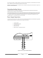
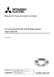
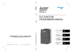
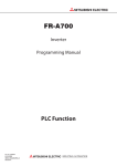
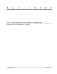
D9142F
24VDC Power Supply
Operation and Installation
Table of Contents:
I.
Description ...................................................................................................................2
II.
Installation
A.
........................................................................................................ 3
Installing the D9142F .................................................................................... 3
1. Mounting the Enclosure .......................................................................... 3
2. Installing the D9142M .............................................................................. 4
3. Installing the D1601 ................................................................................. 4
III.
B.
Connecting AC Power .................................................................................. 4
C.
Batteries ....................................................................................................... 7
1.
Battery Connection ............................................................................... 7
2.
Battery Supervision .............................................................................. 8
3.
Stand-by Battery Calculations ............................................................. 8
D.
Connecting Auxiliary Devices ..................................................................... 9
E.
Power Supply Supervision .......................................................................... 9
F.
LED Indicators ............................................................................................ 11
G.
Switched Output Control ........................................................................... 12
Specifications .................................................................................................... 13
Description
The D9142F is a UL listed, Auxiliary Power Supply for use in Commercial Fire Alarm System
applications. It provides up to 4 amps of power for charging batteries and powering auxiliary or
indicating devices. The D9142F is provided in its own red enclosure that is louvered for ventilation. The
green AC LED and the red Trouble LED are visible through the door. The enclosure also has room to
install two 12 volt, 7 amp hour batteries. Power is supplied to the system via the D1601 Transformer.
This specialized transformer provides power to both the D9142F and to the control/communicator.
The D9142F supervises all critical circuits of the power supply. It provides several installation and
service outputs for troubleshooting. Five different trouble conditions can be recognized and optionally
communicated to the central station. These trouble conditions are also annunciated by on board and off
board LED indicators. A summary trouble relay can be programmed to give a general trouble indication.
Battery Lead Supervision is provided for both batteries when they are connected as described in the
Installing the Batteries section of this manual.
System Components
The D9142F Power Supply is shipped in three separate packages. The D9142M and installation
instructions come in one package. The D8109L comes in a second package and the D1601 transformer
comes in a third package.
Figure 1: D9142F System
F01U036364-03
D9142F Operation and Installation
Page 2
© Bosch Security Systems, Inc.
Figure 2: D9142F Power Supply
You should have the following system components when you receive your D9142F Power Supply:
•
One D1601 Transformer with Dual Secondary Winding
•
One D8109L Louvered Enclosure with lock and key
•
One D9142M Power Supply Assembly which includes the following:
•
D9142LC Power Supply Board
•
D9102 Mounting Skirt
•
Operation and Installation Manual
•
Yellow wiring harness, provides 16.5 VAC to panel
•
Communicator harness, 5 conductor to panel
•
Battery wiring harness with connector
•
Power and Trouble LED assembly
Installation
The D9142F typically is installed adjacent to the Control Communicator. It is compatible with all Bosch
Security Systems, Inc. Control Panels but should only be used with a listed panel for fire alarm applications.
For longer stand-by times, a second battery enclosure may be needed.
Mounting the Enclosure
The D8109L is a louvered version of the standard D8109, UL listed Fire Enclosure. It is supplied with the
standard D101F lock and key set. The D8109L is designed to house the D9142F, the D1601 Transformer
and the batteries. Standard sized knockouts are provided for conduit connections. Enclosures compatible
with the D9142F: Only use the D8109L Enclosure with the D9142F Power Supply. This enclosure is
designed to allow the air circulation needed to keep the power supply cool. The D9142F Power Supply’s
enclosure requires 1/2 inch clearance on all sides.
© Bosch Security Systems, Inc.
D9142F Operation and Installation
Page 3
F01U036364-03
To attach the enclosure to the wall, use mounting hardware that is capable of supporting 55 pounds of equipment. You
may need to mount a plywood sheet to the wall in order to support the weight of the power supply and batteries.
1. Position the enclosure on the surface so that is level.
2. Use the holes to mark the location for anchors.
3. Install anchors into the surface.
4. Using the three top anchor locations, drive the screws about 3/4 of the way in.
5. Hang the enclosure on the partially driven screws.
6. Secure the enclosure onto the surface with screws.
7. Adjust the enclosure so that it is again level and, while holding the enclosure in a level position,
completely tighten the screws. Install screws in holes located toward the bottom of the enclosure.
8. Hang the D9142F onto the hangers at the top of the enclosure.
9. Drive a screw into the tab at the bottom center of the D9142F to secure the mounting skirt to the
enclosure.
Installing the D9142M Power Supply Board
After mounting the D8109L enclosure, locate the D9142M and remove it from its packaging. In this box you should
find three wiring harnesses. Save these harnesses. They will be used later in the installation.
•
Battery Wiring Harness with connector
•
Communicator Output Harness, 5 conductors
•
Panel Power Harness, yellow wires, two conductors
The D9142M power supply mounts in the D8109L enclosure on the mounting tabs provided. Hook the skirt on the
top two Connect power to the 120 VAC input terminals, following these steps:
1. Remove the knockout and install appropriate hardware for connection to conduit.
2. Remove the protective terminal cover marked CAUTION 120 VAC.
3. Pull the 120 VAC Power wires through the conduit hardware installed in the knockout.
4. Connect the wires as marked on the board.
5. Replace the protective cover over the 120 VAC Input terminals.
120 VAC Fuse
The 120 VAC fuse (F1) is located on the lower right-hand corner of the D9142F, above the 120 VAC terminals (see
figure 3). Fuse F1 protects the D9142F and D1601 from damage due to power surges or over loads.
Fuse F1 is a type 3 AG, 4 Amp, 250VDC slow blow fuse. Radionics part number 57-01338-004. Danger: Turn off
the 120 VAC circuit breaker before testing or replacing Fuse F1. Leaving the 120 VAC circuit breaker on can
cause injury or death by electrocution.
If the green AC power LED is off, the 120 VAC circuit breaker is in the ON position, and the building lights and other
electrical devices still operate, Fuse F1 may be open. To replace the fuse, follow these steps:
1. Turn OFF the 120 VAC dedicated circuit breaker.
2. Remove the protective cover from Fuse F1.
3. Pull the fuse from the socket.
4. Using a Volt/Ohm meter verify the 120 VAC has been removed and then test the resistance of the fuse. If
the fuse is open, replace with a new fuse matching Fuse F1’s specification. If the fuse is closed, the
problem may be elsewhere. Call a licensed electrician to troubleshoot any electrical problem.
5. Insert the fuse into the F1 socket.
6. Replace the protective cover.
7. Turn the 120 VAC circuit breaker ON.
F01U036364-03
D9142F Operation and Installation
Page 4
© Bosch Security Systems, Inc.
Connect power to the 120 VAC input terminals, following these steps:
1. Remove the knockout and install appropriate hardware for connection to conduit.
2. Remove the protective terminal cover marked CAUTION 120 VAC.
3. Pull the 120 VAC Power wires through the conduit hardware installed in the knockout.
4. Connect the wires as marked on the board.
5. Replace the protective cover over the 120 VAC Input terminals.
Figure 3: 120 VAC Fuse
120 VAC Fuse
The 120 VAC fuse (F1) is located on the lower right-hand corner of the D9142F, above the 120 VAC terminals (see
figure 3). Fuse F1 protects the D9142F and D1601 from damage due to power surges or over loads.
Fuse F1 is a type 3 AG, 4 Amp, 250VDC slow blow fuse.
Danger: Turn off the 120 VAC circuit breaker before testing or replacing Fuse F1. Leaving the 120 VAC circuit
breaker on can cause injury or death by electrocution.
If the green AC power LED is off, the 120 VAC circuit breaker is in the ON position, and the building lights and other
electrical devices still operate, Fuse F1 may be open. To replace the fuse, follow these steps:
1. Turn OFF the 120 VAC dedicated circuit breaker.
2. Remove the protective cover from Fuse F1.
3. Pull the fuse from the socket.
4. Using a Volt/Ohm meter verify the 120 VAC has been removed and then test the resistance of the fuse. If
the fuse is open, replace with a new fuse matching Fuse F1’s specification. If the fuse is closed, the
problem may be elsewhere. Call a licensed electrician to troubleshoot any electrical problem.
5. Insert the fuse into the F1 socket.
6. Replace the protective cover.
7. Turn the 120 VAC circuit breaker ON.
8. Observe the green AC power LED should be ON.
© Bosch Security Systems, Inc.
D9142F Operation and Installation
Page 5
F01U036364-03
Locating Power Connectors on the D9142F
The D9142 provides power to and receives low voltage AC power back from the D1601 Transformer
(see Figure 4). The D1601 transformer is provided with a wiring harness that is terminated with a
connector. The J8 connector is where the transformer is connected to the D9142.
Figure 4: Plugging in the Power
AC Power for the Communicator
The D9142F can also provide 16.5 VAC, 40 VA to power the control/communicator. The yellow 2
conductor wiring harness supplied in the D9142M package is used for connecting power to the control
panel. This harness connects to the J9 connector on the D9142F (see Figure 4). The other end is
connected to terminals 1 and 2 of the control panel. This option eliminates the D1640 transformer to
power the panel. If the D9142F is to be used to power the panel the D8109L should be mounted next to
the control’s enclosure and joined with conduit.
F01U036364-03
D9142F Operation and Installation
Page 6
© Bosch Security Systems, Inc.
Installing the Batteries
The D9142F uses two sealed lead acid batteries rated at 12 volt, 7 Ah (Radionics D126) connected in series
to provide a 24 volt stand-by power. Two batteries must be used. The power supply will not provide standby power with only one battery connected.
You must use sealed lead acid batteries: The D9142F is designed to charge only sealed lead acid
batteries. Using any other type of battery may cause damage to the D9142F or the batteries.
To install or change the batteries, follow these steps:
1. Switch off the AC Power to the D9142F.
2. Place the batteries in the bottom of the enclosure.
3. Connect red battery leads to red battery terminals and black battery leads to black battery
terminals.
4. Plug the battery harness into connector J7 on the D9142F as shown in Figure 5.
Figure 5: Connecting the battery harness
Here are some important safety tips:
• Connect no more than one battery on a single lead with the supplied battery harness. Important: If two
or more batteries are connected in parallel, battery lead supervision is compromised.
• Do not mix battery sizes, types, or manufacturers when connecting to a power supply.
• Wear insulated gloves and safety goggles while handling
Consult battery manufacturer instructions for further information about batteries and applicable safety precautions.
© Bosch Security Systems, Inc.
D9142F Operation and Installation
Page 7
F01U036364-03
Battery Supervision
The D9142F supervises the batteries for both missing and low battery conditions. To maintain battery lead supervision,
and optimum performance, do not parallel additional batteries on to the power supply.
When the battery is disconnected or the battery voltage drops into the 22 - 24 VDC range, the red Trouble LED lights and
the power supply triggers the Low Battery Trouble output.
When battery is restored and the voltage returns to the 24.2 - 26.5 VDC range, the red Trouble LED is turned off and the
Low Battery Trouble output is reset.
Calculating Standby Power Requirements
Commercial Fire Alarm Systems typically require either 24 or 60 hours of stand-by time. Table 1 is designed to assist
you in determining the battery amperage needed to achieve the desired standby time or current output.
Selecting the Correct Batteries
Selecting the correct batteries for the system depends on the total continuous current draw of all devices, the amount of
stand-by time required, the amount of intermittent current draw (in alarm) needed and finally the time it takes to recharge
the batteries.
Table 1 shows the amount of current (at 24 VDC) that can be drawn for a given battery selection. The calculations used
to create this table include the intermittent current required for five minutes of 3A bell time at the end of the standby
period. When the summary trouble relay is used, subtract 0.02 amps from the available standby current you select from
the table.
Table 1
Example: 7 amp hours of battery capacity (two 12v 7 Ah, D126 batteries installed) provide 24 hours of standby time,
when drawing no more than 0.135 A from the supply continuously. 7 amp hours also provide up to 3 A of alarm power
for indicating devices for five minutes at the end of the stand-by period.
F01U036364-03
D9142F Operation and Installation
Page 8
© Bosch Security Systems, Inc.
Do not connect more than 1.5 amps of stand-by or continuous current to the D9142F. The alarm load can not exceed 3
amps. Together the continuous and alarm load cannot exceed 4 amps.
Example: If your stand-by current or continuous load is 1.5 amps, the alarm power cannot exceed 2.5 amps for all
devices connected to the D9142F.
Connecting Auxiliary Devices
The D9142F has a 4 Amp, 24 VDC Power Supply with a current limited output for powering devices like smoke
detectors, bells, horns, strobes, or other 24 volt devices.
Connect device wiring as shown in Figure 6. Power Limited and Non-Power Limited wiring inside the enclosure should
be kept separate. Maintain at least 1/4” spacing between all field wiring and the AC and Battery harnesses (see Figure
1). Be sure to observe correct polarity when connecting devices, see Technogram F01U036292 for a list of
compatible devices. The terminals 8 and 9 are not functional.
Power Supply Supervision
The D9142F supervise five trouble conditions which can be individually identified back to the central station or grouped to
activate a summary trouble relay. These five trouble conditions are as follows:
•
AC Power Failure
•
On Board AC Fuse Failure
•
Power Output Fault
•
Battery Test Failure
•
Battery Trouble: Low, Missing or Shorted
Figure 6: Connecting Power Output to Devices
© Bosch Security Systems, Inc.
D9142F Operation and Installation
Page 9
F01U036364-03
Trouble Output Header
The five trouble conditions have outputs on the Communicator Output Connector, J3, located on the
D9142F board. This five pin header is located near the bottom left-hand corner of the power supply.
Using the five conductor wiring harness found in the D9142M package, a separate trouble output can be
tied into its own zone or point on the control / communicator. Each output is an open collector that
shorts the zone to ground to indicate a trouble condition. The wiring harness connector is keyed (see
Figure 7).
Select the power supply supervision conditions to be communicated. Connect the appropriate wire to the
positive side of the communicator’s zone input. Install the communicator’s end-of-line resistor across
the communicator’s screw terminals. A ground reference must be established between the power
supply and the communicator. Connect a wire from the D9142F, terminal 7 (- Out) to a common
terminal on the communicator.
Figure 7: Connecting Trouble Output to the Communicator
Summary Trouble Relay
The Summary Trouble Relay can be activated by one or more of the five trouble conditions using the S1
dipswitch. This relay can be used as a common trouble indicator. To activate the relay for a specific
trouble condition, move the switch to the on position. For the factory default settings see Figure 8.
Figure 8: Dip Switch Settings Default
F01U036364-03
D9142F Operation and Installation
Page 10
© Bosch Security Systems, Inc.
Summary Trouble Relay Wiring
When used as a remote trouble indicator, the trouble relay can be wired to trigger trouble sounders or
lights. A form C relay output activates when selected trouble event(s) occur. Wire the relay to switch
positive power to the indicating device as shown in Figure 9.
Figure 9: Connecting the Summary Trouble
LED Indicators
The D9142F has two system status LEDs located on the lower left side of the board. (see Figure 3).
These status LEDs indicate the following:
AC LED
The green AC LED lights when AC Power is connected and
applied to the D9142F. Normally, this LED should be on.
TROUBLE LED
The red Trouble LED lights when the D9142F senses trouble.
Normally, this LED should be off.
POWER OUTPUT LED
The LED lights when the power output is normal. The LED
turns off when there is a fault such as a short circuit
condition on loop.
LED Output Connector
The D9142F has two status LEDs that are visible through the door of the D8109L enclosure. The AC
LED (top) and Trouble LED ( bottom) have the same meaning and actions as the AC LED and Trouble
LED explained above. Connector J5 connects to the wire
harness of the remote status LED assembly. This
assembly mounts in the lower right accessory mounting
location of the D8109L enclosure (see Figure 1). Connect
the Remote LED harness as follows:
1. Knock out the three hole plugs in the lower accessory
mounting position of the D8109L enclosure.
2. Mount the LED assembly with the three screws
provided.
3. Connect the LED assembly wire harness to J5 on
the D9142F board.
Figure 10: Status LED's
© Bosch Security Systems, Inc.
D9142F Operation and Installation
Page 11
F01U036364-03
Figure 11: Connecting Switched Output Control
Switched Output Control
A remote device can switch the D9142F power output on or off with a 12 VDC trigger voltage or a dry contact
closure. When +12 VDC is applied to terminal 2 of the D9142F, the power output is disabled. A dry contact device
can also disable power by shorting terminal 1 and 2 on the D9142F. If using this feature, connect the wire as
shown in Figure 11.
Use this feature to remove power from devices. This feature can apply power to notification devices that require
power during a fire alarm such as horns, strobes and bells. When used for notification appliances the power
supply must be installed within 20 feet of the control unit, and the trigger wire must be in conduit.
Select Power Output Switching
The J1 jumper (see Figure 11) enables or disables Output Control for the power output.
Specifications
Power Input
Power Output
Max Charging Current
DC output
Low Battery Threshold
Low Battery Restoral
Battery Load Shed Threshold
Battery Load Shed Restoral
Summary Trouble Relay
Power Cut
Communication Header
Operating Temperature
Humidity
Batteries
Compatible panels
120 VAC Fuse Rating
UL Listing
120 VAC, 60 Hz 360 VA
4.0 Amps
2.0 Amps
18.9 to 28.0 VDC
22.0 to 24.1 VDC
24.2 to 26.5 VDC
18.9 to 20.5 VDC
23.1 to 24.7 VDC
Form C Rated for 2 A @ 12 or 24 VDC
1K Ω maximum
Open collector output Current sink 5 mA max.
32° - 122° F
85% at 86° F Non Condensing
12 VDC 7 Amp hour Sealed Lead Acid
D7212, D8112, D8124, D9112, D9124
Type 3 AG 4 Amp 250V SB RPN 57-01338-004
UL 1481 Power Supplies for Fire Protective Signaling Systems
FCC Notice
Part 15
This equipment generates and uses radio frequency energy. If not installed and used in accordance with the manufacturer’s
instructions, it may cause interference to radio and television reception. It has been tested and found to comply with the
specifications in Part 15 of FCC rules for Class B Computing Devices.
If this equipment causes interference to radio or television reception - which can be determined by turning the equipment on
and off - the installer is encouraged to correct the interference by one or more of the following measures: 1) Reorient the
antenna of the radio/television. 2) Connect the AC transformer to a different outlet so the control panel and radio/television
are on different branch circuits. 3) Relocate the control panel with respect to the radio/television.
If necessary, the installer should consult an experienced radio/television technician for additional suggestions, or send for
the “Interference Handbook” prepared by the Federal Communications Commission.
© 2008 Bosch Security Systems, Inc.
130 Perinton Parkway, Fairport, NY 14450
(800) 289-0096
F01U036364-03
Operation and Installation
2/08
D9142F
Page 12 of 12