1
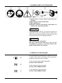
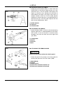
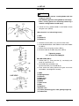
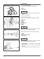
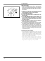
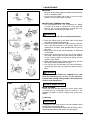
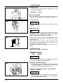
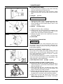
848-KD6-93A1 (806)
OWNER’S MANUAL
BRUSHCUTTERS
BK3410FL
BK4310FL
Caution
• Before using our brushcutter, please
read this manual carefully to understand
the proper use of your unit.
• Keep this manual handy.
SAFETY FIRST
Instructions contained in warnings within this
manual marked with a
symbol concern critical
points which must be taken into consideration to
prevent possible serious bodily injury, and for this
reason you are requested to read all such
instructions carefully and follow them without fail.
■ NOTES ON TYPES OF WARNINGS IN THE
MANUAL
WARNING
This mark indicates instructions which must be
followed in order to prevent accidents which could
lead to serious bodily injury or death.
IMPORTANT
This mark indicates instructions which must be followed,
or it leads to mechanical failure, breakdown, or damage.
NOTE
This mark indicates hints or directions useful in the use
of the product.
Contents
1.
2.
3.
4.
5.
6.
7.
8.
9.
10.
2
WARNING LABELS ON THE MACHINE ………3
SYMBOLS ON THE MACHINE …………………3
SAFETY PRECAUTIONS …………………………4
SET UP ……………………………………………9
FUEL ………………………………………………13
OPERATION………………………………………14
MAINTENANCE …………………………………17
STORAGE…………………………………………20
DISPOSAL ………………………………………20
SPECIFICATIONS ………………………………20
1. WARNING LABELS ON THE MACHINE
(1) Read owner's manual before operating this
machine.
(2) Wear head, eye and ear protection.
(3) Warning/Attention
(4) Keep all children, bystanders and helpers 15
meters away from the brushcutter
IMPORTANT
If warning seals peel off or become soiled and
impossible to read, you should contact the dealer from
which you purchased the product to order new seals and
affix the new seal(s) in the required location(s).
WARNING
Never remodel your brushcutter.
We won't warrant the machine, if you use the
remodeled brushcutter or you don't observe the
proper usage written in the manual.
2. SYMBOLS ON THE MACHINE
For safe operation and maintenance, symbols are carved
in relief on the machine. According to these indications,
please be careful not to take a mistake.
(a) The port to refuel the "MIX GASOLINE"
Position: FUEL TANK CAP
(b) The direction to close the choke
Position: AIR CLEANER COVER
(c) The direction to open the choke
Position: AIR CLEANER COVER
3
3. SAFETY PRECAUTIONS
■ BEFORE USING THE MACHINE
a. Read this owner's manual carefully to understand how
to operate this unit properly.
b. This product has been designed for use in cutting
grass, and it should never be used for any other
purpose .
c. You should never use this brushcutter when under the
influence of alcohol, when suffering from exhaustion
or lack of sleep, when suffering from drowsiness as a
result of having taken cold medicine, or at any other
time when a possibility exists that your judgment
might be impaired or that you might not be able to
operate the brushcutter properly and in a safe
manner.
d. Avoid running the engine indoors. The exhaust gases
contain harmful carbon monoxide.
e. Never use your brushcutter under circumstances like
those described below:
1. When the ground is slippery or when other
conditions exist which might make it not possible
to maintain a steady posture while using the
brushcutter.
2. At night, at times of heavy fog, or at any other
times when your field of vision might be limited and
it would be difficult to gain a clear view of the area.
3. During rain storms, during lightning storms, at
times of strong or gale-force winds, or at any other
times when weather conditions might make it
unsafe to use this product.
f. When using this product for the first time, before
beginning actual work, learn to handling the
brushcutter from skilled worker.
g. Lack of sleep, tiredness, or physical exhaustion
results in lower attention spans, and this in turn leads
to accidents and injury.
Limit the amount of time over which the brushcutter is
to be used continuously to somewhere around 30~40
minutes per session, and take 10~20 minutes of rest
between work sessions. Also try to keep the total
amount of work performed in a single day under 2
hours or less.
h. Be sure to keep this manual handy so that you may
refer to it later whenever any questions arise.
i. Always be sure to include this manual when selling,
lending, or otherwise transferring the ownership of this
product.
j. Never allow children or anyone unable to fully
understand the directions given in this manual to use
this brushcutter.
4
3. SAFETY PRECAUTIONS
■ WORKING GEAR AND CLOTHING
a. When using your brushcutter, you should wear proper
clothing and protective equipment as follows.
(1)
(2)
(3)
(4)
(5)
Helmet
Protection goggles or face protector
Thick work gloves
Non-slip-sole work boots
Ear protectors
b. And you should carry with you.
1. Attached tools and files
2. Properly reserved fuel
3. Spare blade
4. Things to notify your working area (Rope, warning
signs)
5. Whistle (for collaboration or emergency)
6. Hatchet or saw (for removal of obstacles)
c. Never use your brushcutter when wearing pants with
loose cuffs, when wearing sandals, or when barefoot.
■ WARNING CONSIDERING HANDLING OF FUEL
a. The engine of this product is designed to run on a
mixed fuel which contains highly flammable gasoline.
You should never store cans of fuel or refill the fuel
tank in any place where there is a boiler, stove, wood
fire, electrical sparks, welding sparks, or any other
source of heat or fire which might ignite the fuel.
b. Smoking while operating the brushcutter or refilling its
fuel tank is extremely dangerous. Always be sure to
keep lit cigarettes away from the brushcutter at all
times.
c. When refilling the tank always turn off the engine first
and take a careful look around to make sure that there
are no sparks or open flames anywhere nearby before
refueling.
d. If any fuel spillage occurs during refueling, use a dry
rag to wipe up spills before turning the engine back on
again.
e. After refueling, screw the fuel cap back tightly onto the
fuel tank and then carry the brushcutter to a spot 3m
or more away from where it was refueled before
turning on the engine.
5
3. SAFETY PRECAUTIONS
■ THINGS TO CHECK BEFORE USING YOUR
BRUSHCUTTER
a. Before beginning work, look around carefully to get a
feel for the shape of the land, or grass to be trimmed,
and whether or not there are any obstacles which
might get in the way while working, and remove any
obstacles which can be cleared away.
b. The area within a perimeter of 15m of the person
using the brushcutter should be considered a
hazardous area into which no one should enter while
the brushcutter is in use, and when necessary yellow
warning rope, warning signs should be placed around
the work area. When work is to be performed
simultaneously by two or more persons, always check
the presence and locations of others so as to maintain
a distance each person sufficient to ensure safety.
c. Make sure that there are no loose screws or bolts,
fuel leaks, ruptures, dents, or any other problems
which might interfere with safe operation. Be
especially careful to check that there is nothing wrong
with the blades or with the joints by which the blades
are attached to the brushcutter.
d. Never use blades that are bent, warped, cracked,
broken or damaged in any way.
e. Keep the blade always sharp.
f. Filing the cutting edges, keep the end corner sharp
and round the root of the edge.
g. Check the bolt to fasten the blade and be sure the
blade turns smoothly without abnormal noise.
■ NOTES ON STARTING THE ENGINE
1. Take a careful look around to make sure that no
obstacles exist within a perimeter of 15m or less
around brushcutter.
2. Place the body of the brushcutter onto the ground in a
flat clear area and hold it firmly in place so as to
ensure that neither the blades nor the throttle come
into contact with any obstacles when the engine starts
up.
3. Place the throttle into the idling position when starting
the engine.
4. After starting up the engine, if the blades continue to
rotate even after the throttle has been moved fully
back, turn off the engine and check the throttle wire
and other parts.
6
3. SAFETY PRECAUTIONS
■ KICKBACK SAFETY PRECAUTIONS
• A dangerous reaction may occur when the spinning
blade contacts a solid object in the critical area. It is
called Kick back. As a result, the operator can lose
control of the unit which can cause serious or fatal
injury.
Avoid kickback, observe the safety precautions below
strictly.
1. Before beginning work, clear your working area and
remove grasses around the obstacles.
2. When using your brushcutter, do not grip other parts
except the handles.
3. When using your brushcutter, never take your eyes
off. If you need to, place the throttle into the idling
position.
4. When using your brushcutter, do not let the unit get
closer to your feet nor raise the unit above your waist.
■ NOTES ON TRANSPORTATION
a. Make sure the appropriate blade cover is in place.
b. When transporting by car, fix the unit firmly using a
rope. Do not transport by bicycle or motorbike
because it is dangerous.
c. Never transport the brushcutter over rough roads over
long distances without first removing all fuel from the
fuel tank, as doing so might cause fuel to leak from
the tank.
■ OPERATION SAFETY PRECAUTIONS
a. Grip the handle and grip of the brushcutter firmly with
both hands. If you suspend the work, place the throttle
into the idling position.
b. Always be sure to maintain a steady, even posture
while working.
c. Maintain the speed of the engine at the level required
to perform cutting work, and never raise the speed of
the engine above the level necessary.
d. If the grass gets caught in the blade during operation,
or if you need to check the unit or refuel the tank,
always be sure to turn off the engine.
e. If the blade touches a hard object like a stone,
immediately stop the engine and check if something is
wrong with the blade. If so, replace the blade by new
one.
f. If someone calls out while working ,always be sure to
turn off the engine before turning around.
g. Never touch the spark plug or plug cord while the
engine is in operation. Doing so may result in being
subjected to an electrical shock.
h. Never touch the muffler, spark plug, or other metallic
parts of the engine while the engine is in operation or
7
3. SAFETY PRECAUTIONS
immediately after shutting down the engine. Doing so
may result in serious burns.
i. When you finish cutting in one location and wish to
continue work in another spot, turn off the engine and
turn the unit as the blade faces away from your body.
■ MAINTENANCE SAFETY PRECAUTION
a. Perform the maintenance and checking operations
described in this manual at regular intervals. If any
parts must be replaced or any maintenance or repair
work not described in this manual must be performed,
please contact a representative from the store nearest
ZENOAH authorized servicing dealer for assistance.
b. Under no circumstances should you ever take apart
the brushcutter or alter it in any way. Doing so might
result in the brushcutter becoming damaged during
operation or the brushcutter becoming unable to
operate properly.
c. Always be sure to turn off the engine before
performing any maintenance or checking procedures.
d. When sharpening, removing, or reattaching the blade,
be sure to wear thick, sturdy gloves and use only
proper tools and equipment to prevent injury.
e. When replacing blade or any other parts or when
replacing the oil or any lubricants, always be sure to
use only ZENOAH products or products which have
been certified by ZENOAH for use with the
brushcutter.
8
4. SET UP
SE1
■ ATTACHING THE SHOULDER STRAP (SE1)
1. Pass the ring of the shoulder strap through the
hook(A) and fix it by the bolt securely.
2. Set the hook(B) of each shoulder strap to the D-rings
on the frame.
(A) UPPER SIDE
(B) LOWER SIDE
(1) Hook (A)
(2) Bolt (M5x12)
(3) Hook (B)
(4) D-ring
SE2
■ ATTACHING THE LINER
1. Remove the bolt located on the joint of the outer pipe.
(SE2)
2. Match the groove of the liner with the threaded hole
and fix with screw securely. (SE2)
(1) Bolt
(2) Joint
(3) Groove
SE3
3. While rotating the flexible shaft located on the
opposite end from the liner, insert the flexible shaft
into the joint until it is tightly connected. (Note that it
is normal at this time for the flexible shaft not to
project from the liner.) (SE3)
(1) Flexible shaft
(2) Liner
(3) Clutch housing
SE4
5. To connect the clutch housing to the liner, lay the liner
out straight, align the flexible shaft with the angular
hole on the side of the clutch drum, and insert the
liner into the clutch housing, being careful to make
sure that the hole on the end of the liner is facing
directly upwards. When the hole reaches a point
directly below the stopper, you will hear a clicking
sound as the stopper moves into the hole to fix the
liner into place. (SE4)
(1)
(2)
(3)
(4)
(5)
Clutch housing
Stopper
Angular hole
Hole
Liner
• If you experience any difficulty in inserting the liner,
pull out the liner, rotate the flexible shaft slightly, and
9
4. SET UP
try inserting it again.
• Once the liner has been inserted, pull on the liner to
make sure that the stopper is properly engaged.
■ ATTACHING THE THROTTLE CABLE
WARNING
SE5
After fitting the wire, check if the wire sleeve is
correctly fitted to the wire stopper. It is dangerous if
the wire sleeve is out of the wire stopper because
the engine speed will not decrease even if the
throttle lever is released.
• Align the throttle cable along with the liner and tie it
with band. (SE5)
(1) Band
(2) Throttle cable
(3) Tie loosely
SE6
1. Hook the cable and into the hole of the throttle lever.
And set the cable in the lever as shown in the picture.
(SE6)
2. Attach the lever as shown in the picture and screw it
securely. (SE6)
(1)
(2)
(3)
(4)
(5)
10
Throttle lever
Hole
Throttle cable
Screw
Nut
4. SET UP
SE7
■ ADJUSTING THROTTLE CABLE
• Proper play of the throttle cable is 1–2mm. Place the
throttle lever to the lowest speed position (i.e. fully
released status). Pull the throttle cable lightly with
fingers to check its play. Readjust the position of
cable adjuster if the play is too large or too small. To
readjust, slacken a lock nut. Turn the cable adjuster
clockwise to increase the play, or counterclockwise to
decrease the play. Lock the cable adjuster with the
lock nut after readjustment. (SE7)
(1) Cable adjuster
(2) Lock nut
(3) Throttle cable
SE8
■ ATTACHING THE HANDLE
• Attach the loop handle as shown in the accompanying
diagram. Note that it is recommended that you attach
the handle so that the handle is located some
30–40cm away from the front end of the right-hand
grip. (SE8)
(1)
(2)
(3)
(4)
SE9
Loop handle
Screw
Washer
Nut
■ ATTACHING THE DEBRIS GUARD
WARNING
Never use the machine without the debris guard.
• Attach the guard to the clamp on the outer pipe just
touching the gearcase. Fix it with 2 bolts. (SE9)
(1)
(2)
(3)
(4)
(5)
Bolt (M5x25)
Clamp
Debris guard
Place to be attached for blade use
Place to be attached for line head
11
4. SET UP
■ BLADE
WARNING
SE10
• Never attach nor remove a cutting blade while the
engine is running.
• Use ZENOAH genuine cutting blade for exchange.
• Wear sturdy gloves for attaching/removing a
metallic cutting blade to avoid injury.
1. Loosen the nut, remove holder A and holder B from
the gear case. (SE10)
(Note that this is a left-turning screw.)
(1) Bar
(2) Holder B
(3) Holder A
SE11
2. Attach the cover (SE11,(11)) and fix it with screw.
3. Insert blade between cutter holder A and cutter holder
B. (SE11)
4. Attach cover and spring washer. (SE11)
5. Screw the bolt to fix them into place. (SE11)
Tightening torque:
14.7~19.6 N-m/150~200kgf-m
■ LINE HEAD (SE11)
1. Detach bolt (1), spring washer (2), washer(3), bolt
cover (4) and cover (11).
2. Put holder B (5) to holder A (9).
Screw arbor bolt (12) in holder B (5).
3. Then attach the cutting head to the gear shaft over
the holders. Hard-tighten it securely.
(1) Bolt
(2) Spring Washer
(3) Washer
(4) Bolt cover
(5) Holder B
(6) Blade
(7) Gear shaft
(8) Bar
(9) Holder A
(10) Gear case
(11) Cover preventing grass from getting caught up
(12) Arbor bolt
12
5. Fuel
WARNING
• Gasoline is very flammable. Avoid smoking or
bringing any flame or sparks near fuel.
• Wipe up all spills before starting the engine.
• Make sure to stop the engine and allow it cool
before refueling the unit.
• Keep open flames away from the area where fuel
is handled or stored.
IMPORTANT
• Never use oil for 4 cycle engine use or water cooled 2cycle engine.
• Never use "FUEL WITH NO OIL (RAW GASOLINE)".
• Never use fuel laced with water.
• Mixed fuels which have been left unused for a period
of one month or more may clog the carburetor or
result in the engine failing to operate properly. Put
remained fuel into an air-tight container and keep it in
the dark and cool room.
• Please ask for “mixed gasoline for air-cooled 2-cycle
engines” at your nearest gas station, or use fuel made
by putting unleaded gasoline for automobiles and aircooled 2-cycle engine oil into a mixing container in
accordance with the following ratios and then shaking
to mix well.
Mixing ratios:
When using Zenoah genuine 2-cycle oil (FC grade):
50:1 (100 ml of oil for
every 5 liters of gasoline)
When using commercially available 2-cycle oil (FB
grade):
25:1(160 ml of oil for
every 4 liters of gasoline)
13
6. OPERATION
OP1
(1)
(2)
■ STARTING THE ENGINE
1. Pour the fuel and fasten the fuel cap. (OP1)
(1) Cap
(2) Fuel tank
IMPORTANT
• Make sure that the cap is firmly shut and there is no
fuel leak.
• Wipe out the spilled fuel.
OP2
2. Open the fuel cock. (OP2)
3. Move the choke lever to the closed position. (OP2)
(1)
(2)
(3)
(4)
(5)
(6)
Fuel cock
Close
Open
Choke lever
Close
Open
NOTE
OP3
When restarting immediately after stopping the engine,
move the choke lever to the open position.
4. Set the throttle lever to the starting position. (OP3)
(1) Idling
(2) Starting (1/3–1/2 open)
(3) Full throttle
NOTE
OP4
When restarting immediately after stopping the engine,
move the throttle lever to the idling position.
5. While holding the unit firmly, pull out the starter rope
quickly. (OP4)
6. After the engine has started, open the choke
gradually.
7. Allow the engine to run for 2 to 3 minutes to warm up.
14
6. OPERATION
OP5
■
1.
2.
3.
STOPPING THE ENGINE
Return the throttle lever to the idling position.
Push the engine switch button. (OP5)
Close the fuel cock.
(1) Engine switch button
OP6
■ EQUIPPING THE SHOULDER STRAP (OP6)
1. Hold the main pipe with your right hand. Hang the left
strap on your left shoulder.
2. Change your hand to hold the main pipe with your left
hand. Hang the right strap on your right shoulder.
■ CUTTING OPERATION
WARNING
1. Always wear eye protection such as safety
goggles. Never lean over the rotating cutting
head. Rocks or other debris could be thrown into
eyes and face and cause serious personal injury.
2. Keep the debris guard attached in place at all
times when the unit is operated.
OP7
BLADE USAGE (OP7)
• Always cut by guiding the head from your right to left.
• A metal blade cut best up to the point 1/3 from the
edge. Use that area for cutting shrubs, tough and
thick weeds. For cutting young grass, you can use up
to 2/3 from the tip of blade.
• Adjust the engine speed according to the cutting
objects. Cut the young grass at middle speed, and cut
shrubs or tough and thick weeds at high speed.
(1)
(2)
(3)
(4)
For branches and trees
For grass and weeds
Direction of cutting
Direction of rotation
IMPORTANT
Operating at low speed makes it easier for grass, weeds,
or twigs to become caught up in the blades, and also it
makes the shaft and clutch wear down more quickly.
15
6. OPERATION
OP8
LINE HEAD USAGE
• Always remember that the TIP of the line does
cutting. You will achieve better results by not crowding
the line into the cutting area. Allow the unit to trim at
its own pace.
1. Hold the unit so the head is off the ground and is tilted
about 20 degrees toward the sweep direction.
2. Use full throttle when cutting.
3. You can avoid thrown debris by sweeping from your
left to the right.
4. Use a slow, deliberate action to cut heavy growth. The
rate of cutting motion will depend on the material
being cut. Heavy growth will require slower action
than will light growth.
5. Never swing the unit so hard as you are in danger of
losing your balance or control of the unit.
6. Try to control the cutting motion with the hip rather
than placing the full workload on the arm and hands.
7. Take precautions to avoid wire, grass and dead, dry,
long-stem weeds from wrapping around the head
shaft. Such materials can stall the head and cause the
clutch to slip, resulting in damage to the clutch system
if repeated frequently.
ADJUSTING THE LINE LENGTH
• Your brushcutter is equipped with a semi- auto type
nylon line head that allows the operator to advance
the line without stopping the engine. When the line
becomes short, lightly tap the head on the ground
while running the engine at full throttle.
• Each time the head is bumped, the line advance
about 1 inch (25.4 mm). For better effect, tap the head
on bear ground or hard soil. Avoid bumping in thick,
tall grass as the engine may stall by overload.
16
7. MAINTENANCE
MA1
MA2
■ BLADE
• Sharpen each cutting edge and make sure the bottom
corner is rounded. (MA1)
• Do not cool the blade with water in case of using
grinder. It may cause cracks on blade.
■ REFILLING TRIMMING LINE (MA2)
1. For replacement line, use a diameter of .095in
(2.4mm). The spool is capable for a line upto 20ft
(6m) on the 4” head. Avoid using a larger line as it
may cut down the trimming performance.
WARNING
For safety reasons, do not use metalreinforced line.
2. Pinch the slotted area on the both sides of the spool
housing to unhook the bottom cap.
3. Take out the spool and pull off the old line. Fold new
line so that one half line is 4.7in.(12cm) shorter than
another half. And then, hook bended end in the slot of
the spool.
4. Wind up the line in the correct direction as indicated
on the spool.
5. Hook each end of the line in the slot on the edge of
the spool, and then put the ends through the eyelets
on the housing. Make sure that the spring and the
washers are in place.
6. While holding the spool against the housing, pull the
line ends to release them from the slot.
7. Line up the slot on the bottom cap with the hook on
the housing, press the cap against the housing until it
clicks.
WARNING
Make sure that the engine has stopped and is cool
before performing any service to the machine.
Contact with moving cutting head or hot muffler may
result in a personal injury.
MA3
AFTER 25 HOURS OF USE
■ AIR CLEANER
Check and clean the filter element in warm, soapy water
as required. Dry completely before installing. If the
element is broken or shrunk, replace with a new one.
(MA3)
(1) Element
IMPORTANT
A clogged air filter may increase fuel consumption while
cutting down the engine power.
And operate the brushcutter without the air filter or with a
deformed filter element will quickly ruin the engine.
17
7. MAINTENANCE
■ GEAR CASE
• Remove cutter, cutter holder A and plug and insert
fresh lubricant. (MA4)
MA4
(1) Holder A
(2) Plug
■ FUEL STRAINER
Drain the fuel from the tank. Remove the fuel strainer
from the fuel tank and clean the fuel strainer. (MA5)
(1) Fuel Strainer
MA5
IMPORTANT
A clogged fuel filter may cause poor acceleration of the
engine.
■ SPARK PLUG
WARNING
Do not touch the spark plug with bare hands
immediately after stopping the engine. The spark
plug is still so hot and might cause burns.
MA6
0.6~0.7mm
Take out the spark plug, check the electrodes, and if
contaminated, clean them with a wire brush, etc. every
25 hours of use.
When mounting the spark plug, screw the plug in with
your fingers, and then tighten it with the plug wrench
supplied as a standard accessory.
The spark gap should be adjusted to 0.6 to 0.7 mm.
(MA6)
[Tightening torque]
9.8 to 11.8 N-m (100 to 120 kgf-cm)
Designated spark plug
Champion : RCJ-6Y
NGK
: BPMR7A
IMPORTANT
If you use the plug wrench to start tightening the spark
plug, the thread might become damaged.
MA7
■ INTAKE AIR COOLING VENT
• Check the intake air cooling vent and the area around
the cylinder cooling fins, and remove any waste which
has attached itself to the brushcutter. (MA7)
(1) Intake air cooling vent (back)
(3) Cover (4) Screw
(2) Cylinder fin
IMPORTANT
• Note that failing to do so could cause the muffler to
become overheated, and that this in turn could cause
the brushcutter to catch on fire.
18
7. MAINTENANCE
MA8
■ FLEXIBLE SHAFT (MA8)
1. While pulling the stopper of the clutch housing
upward, remove the liner from the unit.
2. Remove the flexible shaft from the liner, apply
lubricant to the shaft, and insert the shaft back into the
liner.
(1) Stopper
(2) Liner
AFTER 100 HOURS OF USE
MA9
■ MUFFLER
1. Remove the muffler, insert a screwdriver into the vent,
and wipe away any carbon buildup. Wipe away any
carbon buildup on the muffler exhaust vent at the
same time. (MA9)
(1) Muffler
MA10
(2) Screw driver
2. Tighten all screws, bolts, and fittings.
3. Check to see if any oil or grease has worked its way
in between the clutch lining and drum, and if it has
wipe it away using oil-free, lead-free gasoline.
4. Remove the float cabin of the carburetor and clean
the inside. (MA10)
(1) Float cabin
■ ADJUSTING CARBURETOR
IMPORTANT
A wrong adjustment may cause damage to your unit. If
the engine does not run well after adjusting the
carburetor, please contact the shop where you
purchased the product.
MA11
■ IDLE ADJUSTMENT SCREW (MA11)
This is the screw to adjust the engine rotation when the
throttle lever is set to the lowest speed position. If you
turn right (clockwise), rotation increases, and left
(counterclockwise) decreases.
In case the blade continues to rotate or engine stops
when you return the throttle lever completely to the
original position, make readjustment.
(1) Idle adjustment screw
MA12
(2) High
(3) Low
■ MAINTENANCE BEFORE STORAGE (MA12)
1. Brushing off dirt form the machine, check damage or
slack of each part. If you find out abnormalities, repair
them for the next use.
2. Extract fuel from the tank, and loose the drain screw
of the float cabin extract fuel, turn on the engine, and
leave it running until it stops naturally.
3. Remove the spark plug and put in 1~2 cc of 2-cycle
oil in the engine. Draw the starter rope 2~3 times, set
the plug back, and stop it at the contraction position.
4. Apply anti-rust oil to the metal parts such as the
throttle wire, put the cover on the blade, and keep it
indoor avoiding dampness.
19
8. STORAGE
Aged fuel is one of major causes of engine starting
failure. Before storing the unit, empty the fuel tank and
run the engine until it uses all the fuel left in the fuel line
and the carburetor. Store the unit indoor taking
necessary measures for rust prevention.
9. DISPOSAL
When disposing your machine, fuel or oil for the
machine, be sure to allow your local regulations.
10. SPECIFICATIONS
Name/Type
Handle Type
Machine Weight (✽1)
kg
Outward Size (L x W x H) mm
Outer pipe
mm
Applied Head
Power Transmission Method
Reduction Rate
Blade Rotating Direction
Type
Displacement Volume cc
Fuel Tank Capacity
Fuel Used
Lubricating Oil Used
Engine
Mixing rate
Carburetor
Sparking Method
Spark Plug
Starting Method
Stopping Method
ZENOAH Knapsack Brushcutter
BK3410FL
BK4310FL
Loop
8.8
9.0
315 x 270 x 410
1500 (ø26)
2-teeth blade(12”), 4-teeth blade, 8-teeth blade, round saw blade(10”), line head
Automatic centrifugal clutch, spiral gear
1.235 (21 : 17)
Counterclockwise (from operator' s view)
Single cylinder air cooling 2-cycle gasoline engine
33.6
41.5
1.3
Lubricating oil mixed gasoline
2-cycle engine oil
when using ZENOAH genuine oil (FC grade): 50:1
when using market oil (FB grade): 25:1
float, piston valve
CDI
Champion RCJ-6Y
Recoil starter
Sparking Circuit Primary Short (push button)
(✽1) excluding cutting head, shoulder strap and fuel
Please note that due to improvement, detailed specifications of the product may differ from the information herein.
Head Office:
1-9, Minamidai, Kawagoe-city, Saitama, 350-1165 Japan
Telephone: (+81)49-243-1117 Telecopier: (+81)49-243-7197