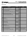
1
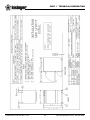
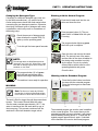
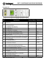
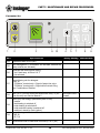
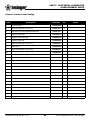
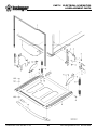
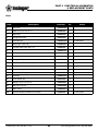
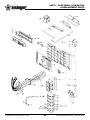
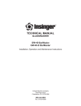
®
TECHNICAL MANUAL
UNDERCOUNTER DISHMACHINE
GS 302
Installation, Operation, and Maintenance Instructions
Insinger Machine Company
6245 State Road
Philadelphia, PA 19135-2996
800.344.4802
Fax 215.624.6966
www.insingermachine.com
Undercounter DOC GS 302 1.0 05
www.insingermachine.com 800-344-4802
®
Thank you for purchasing this quality
Insinger product.
On the space provided below please record the
model, serial number and start-up date of this unit:
Model:__________________________________
Serial Number:___________________________
Start-Up Date:____________________________
When referring to this equipment please have this
information available.
Each piece of equipment at Insinger is carefully
tested before shipment for proper operation. If the
need for service should arise please contact your
local Authorized Insinger Service Company.
A Service Network Listing is provided on our web
site, www.insingermachine.com or call Insinger at
800-344-4802 for your local authorized servicer.
For proper activation of the Insinger Limited
Warranty a SureFire™ Start-Up & Check-Out
Service should be completed on your machine.
Refer to the Introduction section in this manual for
an explanation of Insinger SureFire™ Start-Up &
Check-Out Program.
TABLE OF CONTENTS
Part 1
Technical Information
• Introduction
• Cut-sheets & Installation Drawings
• Warranties
Part 2
Installation Instructions
• Installation and Start-Up Procedures
Part 3
Operating Instructions
• Operating Procedures
• How a Dishwasher Works
2-6
7
8-12
Part 4
Cleaning Instructions/General Maintenance
• Daily and Weekly Procedures
• De-liming Procedures
13-14
Part 5
Maintenance & Repair Procedures
• Troubleshooting
15-24
25-47
Part 6
Electrical Schematics & Replacement Parts
• Machine Wiring Diagrams
• Control Panel Layout & Component Drawings
Please read the Insinger Limited Warranty and all
installation and operation instructions carefully
before attempting to install or operate your new
Insinger product.
To register your machine for warranty by phone,
fax or the internet or for answers to question
concerning installation, operation, or service
contact our Technical Services Department:
TECHNICAL SERVICE CONTACTS
Toll-Free 800-344-4802
Fax
215-624-6966
E-mail
[email protected]
Web
www.insingermachine.com
Undercounter DOC GS 302 1.0 05
www.insingermachine.com 800-344-4802
PART 1
®
Undercounter DOC GS 302 1.0 05
1
TECHNICAL INFORMATION
www.insingermachine.com 800-344-4802
PART 1
®
Undercounter DOC GS 302 1.0 05
2
TECHNICAL INFORMATION
www.insingermachine.com 800-344-4802
PART 1
®
Undercounter DOC GS 302 1.0 05
3
TECHNICAL INFORMATION
www.insingermachine.com 800-344-4802
PART 1
®
TECHNICAL INFORMATION
GS 302 UNDERCOUNTER DISHWASHER
INTRODUCTION
Purpose
The purpose of this technical manual is to provide
installation, operation, cleaning and maintenance
directions.
Intended use
The Insinger dishwasher GS 302 may only be used
for cleaning plates, cups, dishes, cutlery and similar
restaurant ware and commercial catering.
A section is provided for replacement parts.
Any change in design or use of the dishwasher carried out without the written permission of Insinger,
will lead to warranty nullification.
Scope
This manual contains all pertinent information to
assist in the proper installation, operation, cleaning,
maintenance, and parts ordering for the Insinger
GS 302 Undercounter Dishwasher.
If damage is caused to the dishwasher due to failure to observe the instructions given in this manual,
no claims under the warranty agreement can be
submitted to Insinger Machine Company.
The installation instructions are intended for
qualified equipment installers. The operation and
cleaning instructions are intended for the daily
users of the equipment. The maintenance and
parts sections are intended for qualified service
and/or maintenance technicians. Replacement
parts may be ordered directly from our factory
or from your local Insinger Authorized Service
Agency. You can speak to the Insinger Technical
Services Department, 800/344-4802, or e-mail us
at [email protected]. When calling
for warranty information or replacement parts
please provide the model and serial number of your
Insinger Equipment. These important numbers
should be noted in this manual on the spaces
provided on the opening page.
Safety Instructions
Make sure that you have read and understood the
operating instructions before you start to use the
dishwasher. The Insinger customer service department can tell you how to operate the washer and
how it works.
Definitions
Throughout this guide you will find the following
terms: WARNING, CAUTION, & NOTE.
WARNING indicates potential physical danger.
CAUTION indicates potential equipment damage.
NOTE indicates helpful operating hints or tips.
You will visually be able to identify each as
shown below:
Surefire™ Start-up & Check-out Program
Insinger is proud to offer our exclusive Surefire™
Start-up & Check-out Program to our commercial
customers. This service is included in the purchase
price of your new Insinger dishwasher. We will
provide an authorized factory service technician for
the initial start-up of your new Insinger dishwasher
to ensure it is running at optimum levels from the
very first pass. Please call the factory or your local
Insinger Sales Representative to schedule this
service.
!
Indicates potential physical danger.
;
NOTE:
Indicates helpful operating hints or tips.
NSF 3-2003 requirements for detergent
and chemical sanitizer dispensers.
This machine must be operated with detergent in
the integral detergent dispensing system to insure
proper washing.
Undercounter DOC GS 302 1.0 05
WARNING:
CAUTION:
Indicates potential equipment damage.
4
www.insingermachine.com 800-344-4802
PART 1
®
TECHNICAL INFORMATION
INSINGER MACHINE COMPANY LIMITED WARRANTY
Insinger Machine Company, Inc. (Insinger) hereby
warrants to the original retail purchaser of this
Insinger Machine Company, Inc. product, that if it
is assembled and operated in accordance with the
printed instructions accompanying it, then for a
period of either 15 months from the date of
shipment from Insinger or 1 year (12 months) from
the date of installation or start-up that said Insinger
product shall be free from defects in material and
workmanship. Whichever one of the two aforestated
limited warranty time periods is the shortest shall
be the applicable limited warranty coverage time
period.
the instruction booklet (operating instructions) or
for improper operation or failure to follow normal
operating instructions (as set out in the instruction
booklet). Insinger is not responsible nor liable for
any conditions of erosion or corrosion caused by
corrosive detergents, acids, lye or other chemicals
used in the washing and or cleaning process.
Service must be done by either Insinger Appointed
Service Agencies or agencies receiving prior
authorization from Insinger.
All warranty work must be done during normal
working hours, unless purchaser receives prior
authorization from Insinger.
Insinger may require reasonable proof of your date
of purchase; therefore, you should retain your copy
of invoice or shipping document.
There are no other express warrants except as set
forth herein and any applicable implied warranties
of merchantability and fitness are limited in
duration to the period of coverage of this express
written limited warranty. This limited warranty
supersedes all other express warranties, implied
warranties of merchant-ability and fitness or
limited warranties as of this date, January 1, 1998.
Some states do not allow limitation on how long
an implied warranty lasts so this limitation may
not apply to you.
This limited warranty shall be limited to the repair
or replacement of parts which prove defective under
normal use and service and which on examination
shall indicate, to Insinger’s satisfaction, they are
defective. Any part that is claimed to be defective
and covered by this limited warranty must be
returned to Insinger, this may be done through an
Authorized Service Agency. Furnish serial number
of machine with shipment and send to:
Insinger Machine Company
6245 State Road
Philadelphia, PA 19135-2996
Insinger is not liable for any special, indirect or
consequential damages. Some states do not allow
the exclusion or limitation of incidental or consequential damages, so this limitation nor exclusion
may not apply to you.
If Insinger’s inspection confirms the defect and the
claim, Insinger will repair or replace such part
without charge and return it to you freight or postage prepaid.
Insinger does not authorize any person or company
to assume for it any other obligation or liability in
connection with the sale, installation, use, removal,
return or replacement of its equipment: and no such
representations are binding on Insinger.
This limited warranty does not cover any failure or
accident, abuse, misuse, alteration, misapplication,
improper installation, fire, flood, acts of God or
improper maintenance or service, or failure to perform normal and routine maintenance as set out in
Undercounter DOC GS 302 1.0 05
5
www.insingermachine.com 800-344-4802
PART 1
®
TECHNICAL INFORMATION
INSINGER MACHINE COMPANY LIMITED WARRANTY
COMMERCIAL MARINE USE
Labor will be billed to the customer at a reduced
rate of $40.00 per hour. If sailing with a vessel is
required, then an eight hour per day minimum will
apply.
Insinger Machine Company, Inc. (Insinger) hereby
warrants to the original retail purchaser of this
Insinger Machine Company, Inc. product, that if it
is assembled and operated in accordance with the
printed instructions accompanying it (installation
manual), then for a period of 15 months from the
date of installation on board the vessel, that said
Insinger product shall be free from defects in
material and workmanship.
This limited warranty does not cover accident,
abuse, misuse, alteration, misapplication, improper
installation, fire, flood, or improper maintenance or
service, or failure to perform normal and routine
maintenance as set out in the instruction booklet
(operating instructions) or for improper operation
or failure to follow normal operating instructions
(as set out in the instruction booklet).
Insinger may require reasonable proof of your date
of equipment install, therefore, you should retain
your copy of invoice or shipping document.
This limited warranty shall be limited to the
replacement of parts which prove defective under
normal use and service and which on examination
shall indicate, to Insinger's satisfaction, they are
defective. Any part that is claimed to be defective
and covered by this limited warranty must be
returned to Insinger. Furnish serial number of
machine with shipment and send to:
Insinger is not responsible nor liable for any conditions of erosion or corrosion caused by corrosive
detergents, acids, lye or other chemicals used in the
washing, caring and or cleaning process.
Insinger Machine Company, Inc.
6245 State Road
Philadelphia, PA 19135-2996
There are no other express warrants except as set
forth herein and any applicable implied warranties
of merchantability and fitness are limited in duration to the period of coverage of this express written
limited warranty. This limited warranty supersedes
all other express warranties, implied warranties of
merchantability and fitness or limited warranties as
the above date.
Warranty service must be done by either Insinger
Appointed Service Agencies or agencies, customers
galley engineers receiving prior authorization from
Insinger.
If Insinger's inspection confirms the defect and the
claim, Insinger will repair or replace such part
without charge and return it to you freight or postage prepaid. If part damages are not covered,
Insinger will contact the customer and advise.
Insinger does not authorize any person or company
locally or overseas to assume for it any other
obligation or liability in connection with the sale,
installation, use, removal, return or replacement
of its equipment; and no such representations are
binding on Insinger.
If a factory trained authorized technician is
required to repair or replace defective parts or material during the 18 month warranty period, the
cruise line will be responsible for the payment of
travel expense and a minimum of four hours labor.
Undercounter DOC GS 302 1.0 05
6
www.insingermachine.com 800-344-4802
®
PART 2
INSTALLATION INSTRUCTIONS
INSTALLATION AND CONNECTION
!
Connection to the Power Supply:
Before using the washer, check that all electrical
protection systems are working correctly.
Attention: The machine should not be regarded
as isolated from the power supply unless
switched off at the customer’s main switch.
WARNING:
Installation and connection of the washer to
the customer’s water inlet, waste water
drainage and electric connections are to be
carried out in accordance with national and
local criteria by qualified engineers.
Check for Completeness:
After unpacking the machine, first check the delivery
against the packing slip to ensure that it is complete,
and inspect for damage that may have occurred
during transportation. Immediately report any
damage to the carrier, the insurance company and
the manufacturer.
!
Do not connect a 208V machine to 240V
service or visa versa. Connect machine to
labelled power.
• The total amp load of the washer depends on the
electrical characteristics; 208 Volt single phase 60
Hz equals a load of 27.4 fla, 240 Volt single phase
60 Hz equals a load of 25 fla. (This data is also
shown on the machine’s rating plate.)
Setting Up and Alignment:
When setting up the machine, remember that the
machine gives off steam during operation (when
you open the door). Protect adjacent wooden furniture to prevent it absorbing moisture and swelling.
• The electrical connection of the washer is to be
fused by the customer with time-lag fuses or circuit
breaker according to wattage (see the machine rating plate). No other appliances may be fused with
the washer.
CAUTION:
Protect the washer against frost. Systems that carry
water can be damaged if they freeze.
• Install according to regulations, an isolator or a
control switch and a residual current circuit-breaker;
the 208 Volt unit requires a 35 amp circuit breaker
and the 240 volt unit requires a 30 amp circuit
breaker in the electric supply. These switches
must switch off all poles and have at least 3 mm
contact distance. The place of installation must be
near the washer and easily accessible.
The machine must be completely level prior to
installation. Adjust the machine’s feet to compensate for any unevenness of the floor.
CAUTION:
Note all the information on the enclosed connection
diagram. For the machine to work correctly,
the required water pressure and flow rate must be
guaranteed at all time.
• Connect the power cord to the customers power
system. Note voltage of machine (either 208 volt or
240 volt) and connect power cord to the appropriate
supply. (The power cord can be wired directly into
the customers power supply or a plug may be
added to the end of the cord. The ground wire is
green, neutral is white and live is black.) make sure
the unit is properly grounded.
Connection to the Water Supply:
• Use a ball valve for the water supply and drain
near the washer and in an easily accessible
position. It should not be located behind the
washer.
• The power cord comes attached from the factory, if
replacement is required note: the ground wire (PE)
is yellow-green, the neutral conductor (N) is blue
and the live wires (L1, L2, L3) are black or brown.
• Use the hose and dirt catcher strainer (PART
NO. 80002153) provided with the washer to
connect it to the water supply. The filter must
be installed.
Final Tasks:
The washer must be connected to all services (electricity
supply and to the fresh water and waste water systems),
prior to testing the machine & installation.
• The washer is equipped with a drain pump.
The maximum drain pump lift above floor is 24”.
Undercounter DOC GS 302 1.0 05
WARNING:
7
www.insingermachine.com 800-344-4802
PART 3
®
OPERATING INSTRUCTIONS
OPERATING INSTRUCTIONS
Operating Panel
The operating panel is situated in the upper part of the machine.
1
2
C
D
E
A
3
B
5
7
8
6
9
Button Function Chart
1
On/Off switch
2
Tank drainage/self cleaning
C
Indicator lamp for fault
D
Indicator lamp for lack of detergent or rinse aid
E
Indicator lamp for salt refill on softener supplied units
3
Control button
A
Temperature display – Final rinse/booster or parameter index
B
Temperature display – Wash tank or parameter valve
4
Function button – activates the special programs (10-13)
5
Parameter index down
7
Parameter valve down
8
Parameter valve increase
6
Parameter index increase
9
Button area for special programs
Undercounter DOC GS 302 1.0 05
4
8
www.insingermachine.com 800-344-4802
PART 3
®
HOW THE DISHWASHER WORKS
OPERATING INSTRUCTIONS
As soon as the target temperatures are reached,
(wash water approximately 150°F; final rinse water
approximately 180° F) the washer is ready for
operation. The program button (6) then lights up
green.
When the machine is switched on, the booster
and wash tank fill and are heated to operating
temperature. The program button (6) is lit red
during heating. The booster preheats the wash
water before pumping to the wash tank. This
preheat/pumping sequence takes about 6-8 cycles
(about 30-45 minutes) before filling & heating the
wash tank.
The machine is operated using fully-automatic
programs. These consist of three steps: washing,
draining and rinsing. The program button (6) is lit
blue during the wash and rinse cycle and green
when it is finished & ready for another load. It is lit
red when it is
• Switch on machine by pressing button 1.
• The tank is filled in stages by way of the boiler:
Washing: The wash pump circulates the wash
water from the tank onto the dishes and ware
via the wash arms and jets. As the wash water
circulates, it constantly passes through a filter
system and the patented Mediamat Cyclo
(removing foreign particles from the water).
Detergent is added by means of an integral dosing
pump for liquid detergent. It is dosed from the
storage tank behind the front panel.
• The boiler is first completely filled until the
electronic level control switches off.
• The boiler heats up.
• The tank is filled by way of the rinse pump for a
certain period of time.
• When the boiler is filled again heated up, the tank
is again filled for a certain period of time by way
of the rinse pump.
• This continues until the target values (level,
Draining: After washing, there is a brief pause to
allow the wash water to drain off the ware and to
reset the water level for the next run.
temperatures) for boiler and tank are reached.
• During filling, button 3 glows red and the
temperatures of the tank (in Display B) and the
boiler (in Display A) are shown.
Rinsing: In the final step of the program, the
cleaned dishes are rinsed with fresh hot water to
remove any detergent residue and to heat up the
dishes for optimum drying outside the machine.
The rinse water also replaces the wash water. An
integral dosing pump doses the rinse aid from a
storage tank behind the front panel.
• When the target values (level, temperatures)
have been reached, the temperature display
goes out and button 3 is lit green.
!
WARNING:
Do not open the door while the program is
running. There is a risk of hot water spraying
out of the machine. (The unit is equipped
with a door safety switch, located behind the
door.)
CAUTION:
Do not place anything on the open door.
Undercounter DOC GS 302 1.0 05
9
www.insingermachine.com 800-344-4802
PART 3
®
OPERATING INSTRUCTIONS
WASH PROGRAMS
The dishwasher can operate in a normal time cycle or an extended time cycle (additional 80 seconds added
to the wash cycle.) The individual programs are selected by means of the control panel.
Program (button)
Description
Normal Program (3)
For normal soiling.
Medium drying time.
Extended Program (4)
For heavy soiling.
Long drying time.
Tank Drainage / Chamber Rinse (2)
Rinsing of the inside wash chamber:
Circulation of the wash water inside the wash chamber.
Pumping out the wash water.
Flushing out the wash chamber with fresh hot water.
Pumping out the used fresh water.
The washer switches off automatically when the program is finished.
This is not a substitution for deliming.
Before Washing
Verify water & electricity are available for the machine.
Adding Rinse Aid and Detergent:
CAUTION:
Turn ball valve to open position.
Only use detergent and rinse aid which are
suitable for commercial washers,
a non-foaming industrial alkaline detergent.
Switch on the main switch.
Do not use any soap intended for a residential
dishwasher. This leads to large amounts
of foam building up in the washer and
will void your manufacturers warranty.
Check the Filter System:
CAUTION:
Open the door.
Detergents for commercial dishwashers
cause corrosion. Always follow the instructions
on the packaging and drums.
Check that the scrap screen is
inserted correctly.
Turn on Machine:
CAUTION:
Close the door.
Do not mix different detergent products,
this could cause the dosing pump to break down
due to crystallization.
Press On/Off switch (1), heating up
phase begins.
The program button (3) is lit red:
the booster and tank are filling and
heating up.
Undercounter DOC GS 302 1.0 05
10
www.insingermachine.com 800-344-4802
PART 3
®
Changing the Detergent Type.
If changing to a different detergent type (even one
by the same manufacturer), you must rinse the
suction and pressure hoses with fresh water before
connecting the new detergent container. Otherwise,
the mixing of different types of detergent will cause
crystallization, which may result in a breakdown of
the dosing pump.
OPERATING INSTRUCTIONS
Washing with the Normal Program
Push the full wash rack into the machine and close the door.
Press program button (3). The program button is lit blue while the cycle
is running.
Check the amount of detergent and
rinse aid when the symbol DOS (D)
lights up on the operating panel.
The program button lights up green
when the cycle is complete.
To do this pull the lower panel forwards.
;
Open the door and remove the wash
rack. The intrinsic heat of the wares
and the effect of the rinse aid added to
the rinsing water combine to quickly
dry the wares. Do not dry recently
cleaned dishes with a towel to avoid
spreading bacteria and germs.
NOTE:
The storage tanks are identified with words
“detergent” and “rinse aid”. When filling, make
sure that no detergent goes into the rinse aid
container or vice versa.
Close the door.
The program button (3) is lit green
when the tank and booster have
reached their target temperatures.
Washing with the Extended Program
The machine is now ready for operation.
WASHING
;
Press the function button to activate
the area with the extended program.
Press the button again to deactivate
this area.
Note:The first run of each day OR after
the machine is drained will be delayed due
to the manner in which the GS 302 is filled.
The tank is filled in stages through the pressureless
booster. The booster fills and heats the water.
One the water reached approximately 150 °F, the
water is transferred into the wash tank by way of
the rinse pump. This process continues until the
wash tank is filled and heated to target values.
Undercounter DOC GS 302 1.0 05
3
4
The extended program can now be used in addition
to the normal program. This means that once the
extended program has been selected, it will always
be activated by pressing button 3. To clear the extended program press button 4 again. If switched
off the machine will revert to the normal program.
11
www.insingermachine.com 800-344-4802
PART 3
®
OPERATING INSTRUCTIONS
WASHING (CONTINUED)
Extensive Program
Use: Depending on the level of soiling on the wash
items, select the button indicating extended wash
time.
Press the button to select the
extended wash program.
;
NOTE: The short cycle is not available with
this machine.
Press the button to start the program.
Draining the Tank; Rinsing the Chamber
Remove the rack.
Close the door.
Hold down the function button for
three seconds to start the rinsing
program. (See section 9 of the
Operating Manual for deliming
instructions.) The function button
flashes.
The wash water is then circulated inside the wash
chamber while it is pumped out. The machine
interior is finally flushed out with hot fresh water.
The washer switches off automatically when the
rinsing program is finished. The operating panel is
no longer lit.
Undercounter DOC GS 302 1.0 05
12
www.insingermachine.com 800-344-4802
PART 4 GENERAL MAINTENANCE
®
GENERAL MAINTENANCE
The washer should be regularly cleaned to ensure
that it remains reliable and in good working order
for many years to come.
Reinsert the bottom wash trays.
CAUTION:
Clean the outer walls of the washer
with cleaning products for high grade
stainless steel.
Do not spray the outside of the washer with a high
pressure or steam jet cleaner.
Every Day After Washing
Open the door slightly using the to the
vent position. This will allow the interior to dry more easily, which is important for long-lasting protection against
corrosion – even for stainless steel.
Remove the filter cartridge, clean it
under running water and reinsert.
If the flat filter is very dirty remove the
bottom wash trays and rinse them with
water.
DELIMING PROCEDURES
FOR THE GS 302
!
Remove the flat filter with the filter cartridge and clean it under running water.
Use a brush to remove any deposits
inside the machine.
The GS 302 must be kept free of lime for
proper operation. Lime will interfere with
normal function.
Machines that are operated in hard water areas and
do not have an integral water softener or are not
connected to an external water treatment system
must be de-limed from time to time. There are
de-liming agents specially designed for commercial
washers available for this purpose, please consult
your detergent supplier.
During cleaning, make sure that no
rusting foreign bodies remain inside the
washer. This can cause the interior to
rust. The foreign bodies may come from
non-stainless steel items washed,
cleaning aids, damaged wire racks or
from supply lines which have not been
rust-proofed.
CAUTION:
De-liming agents for commercial dishwashers cause
corrosion. Always follow the instructions for use and
safety instructions on the packaging and drums.
Reinsert the flat filter with the filter
cartridge.
Undercounter DOC GS 302 1.0 05
WARNING:
13
www.insingermachine.com 800-344-4802
PART 4 GENERAL MAINTENANCE
®
DELIMING PROCEDURES
FOR THE GS 302 (CONTINUED)
C
1
1.
2
3
A
Note and record detergent dose setting.Turn
off unit (Button 1) Press and hold Buttons 2 &
3 simultaneously, while holding these buttons
press button 1. P11 in visible display A. Note
value in display B.
2.
Press Button 7 (to decrease detergent
dosage) until display B display reads “10”.
3.
Press button 4 to store value.
4.
Drain Machine. Press and hold button 2 for
three seconds (until you hear the wash pump
start.) The machine will rinse then drain.
When complete the operating panel will no
longer be lit.
6.
Turn on machine. Press on/off button.
7.
Refill machine. (Press button 3.)
8.
Open door add deliming agent directly into
the tank.
Undercounter DOC GS 302 1.0 05
B
4
5
7
8
6
8.
Run extended program. (Press button 4 then
Press button 6 (extended cycle.) Press button
3 to run cycle.
9.
After cycle completes, open door and inspect.
If additional deliming is required repeat steps
7 & 8.
10. When deliming procedure is complete, reset
the detergent dosage back to original.Turn off
unit (Button 1) Press and hold Buttons 2 & 3
simultaneously, while holding these buttons
press button 1. (P11 in display A) Press
Button 8 (to increase detergent dosage) until
B display reads same as original. Press 4 to
store drain machine.
11. Drain Machine. Press and hold button 2 for
three seconds (until you hear the wash pump
start.) The machine will rinse then drain.
When complete the operating panel will no
longer be lit.
12. Machine is ready for use.
14
www.insingermachine.com 800-344-4802
PART 5 MAINTENANCE AND REPAIR PROCEDURES
®
Combination of Buttons
C
1
2
Button
3
Function
A
B
4
Remark
5
7
8
Button
6
Function
1. Set Up Parameter Mode
3. Quit parameter mode or test mode
1
Switch off machine
1
Switch off machine
ON
Set service switch to ON
OFF
Set service switch to OFF
1
Switch on machine
1
Switch on machine
5
Parameter backwards
6
Parameter forwards
7
Parameter value backwards
Display A:
P00=parameter
set
P01-P050=
parameters
4. LED—Test
1
Parameter value forwards
4
Store parameter value
Switch off machine
ON
Set service switch to ON
1
Switch on machine
3
Keep pressed for 3 sec.
5
Actuator backwards
6
4
Actuator forward
Switch on/off input or output
Undercounter DOC GS 302 1.0 05
Keep pressed
Switch on customer’s main
switch
1+2
2. Set up test mode
1
Switch off machine
Switch off customer’s main
switch
Display B:
Parameter
value
1+2
8
Remark
Release buttons
Each LED can
be tested by
pressing
Quit by switching off main
switch
5. Display operating data
1
Switch off machine
4+8
Keep pressed
1
Switch on machine
5
Operating hours
Display: value x
hours
6
Water consumption
Display: value x
10 litres
7
Wash cycles
Display: value x
cycles
Display A: —-
To select Output (A)/Input
(E)
15
www.insingermachine.com 800-344-4802
®
PART 5 MAINTENANCE AND REPAIR PROCEDURES
Combination of Buttons
C
1
2
Button
3
Function
A
B
4
5
7
8
6
Remark
6. Prime the detergent unit, set concentration
Direct to P11
1
Switch off machine
2+3
Keep pressed
1
Switch on machine
2
Keep pressed to ventilate
unit
7
Decrease dosage of detergent
8
Increase dosage of detergent
4
To store altered value
P11 in display
A
Value x 0,1 ml/
L
Button 3 glows
red
7. Prime the rinse aid unit, set concentration
Direct to P10
1
Switch off machine
2+3
Keep pressed
1
Switch on machine
3
Keep pressed
2
Press twice
2
Keep pressed to ventilate
unit
7
Decrease dosage of rinse
aid
8
Increase dosage of rinse aid
7
To store altered value
Undercounter DOC GS 302 1.0 05
P10 in display
A
Value x 0,1 ml/
L
Button 3 glows
red
16
www.insingermachine.com 800-344-4802
PART 5 MAINTENANCE AND REPAIR PROCEDURES
®
Parameter Set
C
1
2
3
SET
A
B
4
5
7
8
6
Specification
Factory Setting
Multiplicator
P00
Parameter set
121 Standard
120 w/water softener
P01
Tank target temperature
Tank filling temperature:
Min. temperature 169°F (P01+15)
Max. temperature 185°F (P01+31)
154
°F
P02
Boiler target temp. 1
182
°F
P03
Boiler target temp. 2 (149) Option
149
°F
P06
Time of wash pump, normal program (135sec)
27
5 sec.
P07
Time of wash pump, intensive program (215sec)
43
5 sec.
P08
Rinse time (11sec)
11
Attention: P09 must be modified accordingly if P08 is changed!
sec.
P09
Rinse quantity is required for the calculation of the detergent
and rinse aid dosage
28
0,1 litre
P10
Rinse aid concentration
See “Combination of Buttons”
30
0,01 ml/L
P11
Detergent concentration
See “Combination of Buttons”
30
0,1 ml/L
P13
The first programe run take place:
Value 1: after the tank temperature was attained
Value 0: Before the tank target temperature has attained.
0
P14
Continuous temperature display (1:yes/0:no)
1
P17
Quantity restrictor (pressue boiler: 15L/pressureless boiler: 5L) 50
P18
0: No function
1: Countdown device installed
0
P21
Reset countdown device (set value 1 to reactivate)
See “Combination of Buttons”
0
P22
Quantity of water for countdown device
20
Undercounter DOC GS 302 1.0 05
17
0,1 litre
1000L
www.insingermachine.com 800-344-4802
PART 5 MAINTENANCE AND REPAIR PROCEDURES
®
Parameter Set
C
1
SET
2
3
A
B
Specification
4
5
7
Factory Setting
P24
Simple door start (0:no/1:yes)
P25
Error management (1: activated/0: not activated, however the
1
safety criterias are activated)
P26
Automatic tank draining and refilling
2: yes if tank temp. is below 118° F
0: not activated
2
P27
Type of dosing unit for detergent
3: MP 28
5: “Fill/Water” terminal strip = Signal of water inlet valve
4: “Fill/Water” terminal strip = Signal while first tank filling
See “Combination of Buttons”
3
P32
With P32-37 you can control the Multifunction relay. To program the relay see Service Manual 2
See technical doc. 2
to install
P38
EZEO (only with energy optimization plant on site)
0: inactive
1: tank heating is switched off
2: boiler heating is switched off
3: boiler and tank heating is switched off
4: machine in stand by mode (option)
0
P39
Type of dosing unit for rinse aid
2: MP 28
1: ELT 10
2
P44
Pressureless boiler is filled while final rinse (0: no/1: yes)
0
Undercounter DOC GS 302 1.0 05
8
6
Multiplicator
0
18
www.insingermachine.com 800-344-4802
PART 5 MAINTENANCE AND REPAIR PROCEDURES
®
Inputs and Outputs
C
1
2
3
A
B
4
5
7
8
6
Test Mode (table for output/input)
Display A
Specification
Safety Criteria
Display B
101
Tank heating 1
Min. tank level present
Temp. below 182°F
A02
Boiler heating
Min. boiler level present
Boiler temp. in °F
Temp. below 182°F
A03
Soft starter for wash pump
Door closed
A08
Relay soft start
A09
Rinse pump M3
Door closed
Tank level in mm
A10
Dos. Rinse Aid
Door closed
1 or 0
A11
Dos. Detergent
Door closed
1 or 0
A12
Drain pump
Tank level in mm
A13
Pressureless boiler valve Y3
1 or 0
Tank temp. in °F
Tank level in mm
0
Input
E01
Tank temperature
E02
Boiler temperature
E03
Tank level
E11
Lack of detergent or rinse aid. Signal: DOS
E12
Filling level of pressureless boiler
E14
EZEO
1 or 0
E16
Door
1 (closed) 0 (open)
Undercounter DOC GS 302 1.0 05
19
1 or 0
www.insingermachine.com 800-344-4802
®
PART 5
MAINTENANCE & REPAIR PROCEDURES
TROUBLESHOOTING
Work on the electrical equipment should only be
performed by service personnel. First disconnect
the washer from the main power switch. Do not
switch the washer on again until the cause of the
fault has been identified.
Faults where it is not necessary to call Insinger.
You can rectify minor faults yourself following the
steps described in the table below. If you are unable to rectify the fault, contact Insinger service
(1-800-344-4802.)
!
Do not open any panels or expose any parts of the
machine if tools are necessary to do so. Risk of
electric shock.
Display
The Washer Cannot
Be Switched On
Wash Program
Does Not Start
DOS
Turn off the main switch on the dishwasher
so it is isolated from the power supply.
Cause
Remedy
Main switch on the machine is not
switched on
Switch on the customer’s main switch
Customer’s fuses blown
Replace the customer’s fuses
Door not fully closed
Close the door
Machine not ready for operation
Switch on at the customer’s main switch,
open the water stop valve and switch on
the machine
Detergent or rinse aid storage tank is
empty
Dishes Are Not Clean
WARNING:
Top off the detergent or rinse storage tank
Filter cartridge and/or scrap screen is
dirty
Clean the filter cartridge and scrap screen
Wash jets in the wash arms blocked
Clean wash jets
Lack of detergent or rinse additive
Re-fill detergent or rinse additive
Display Shows
Turn off the dishwasher (Press the on-off
switch). Then the display should show Err
and a fault code.
Water stop valve closed
Open the water stop valve and turn the
machine on again.
Malfunction
If the fault message reappears, note the
fault code and contact Insinger Service.
Button is Flashing Blue
If the dishes have not been sufficiently
pre-rinsed, so much dirt may have accumulated on the scrap screen and the cartridge filter that the wash program's operation is interrupted. The wash pump
turns itself off and the program button
flashes blue.
Undercounter DOC GS 302 1.0 05
20
Turn off the machine, the program button
continues to flash.
Remove the screens, clean and replace.
After 2 minutes the flashing will stop. Turn
the machine on again and continue to use.
In order to avoid further problems please
ensure better pre-rinsing.
www.insingermachine.com 800-344-4802
PART 5
®
MAINTENANCE & REPAIR PROCEDURES
TROUBLESHOOTING (CONTINUED)
Faults where it is necessary to call Insinger Service.
Display
Possible Cause
Flashing light: Temperature in booster or tank is greater than 203°F.
Caution: Surface is very hot.
The fault (3) symbol appears together with the fault code Err 2 or Err 3.
Switch off main switch.
Notify the Insinger service team immediately.
When the machine can no longer be used because of internal faults, the machine turns itself off automatically and
displays an error code. See chart below.
Display
Possible Cause
Remedy
Machine Shuts Down
and Displays
Err 1
Internal fault.
Machine Shuts Down
and Displays
Err 6
Internal fault or water flow blocked. Inform Insinger Service and/or remove the blockage.
Machine Shuts Down
and No Longer Displays
Anything
Inform Insinger Service.
Internal fault.
Undercounter DOC GS 302 1.0 05
Inform Insinger Service.
21
www.insingermachine.com 800-344-4802
®
PART 5 MAINTENANCE AND REPAIR PROCEDURES
Error Management
Error
Code
Fault Description
Machine/Fault
Reaction
Cause
Panel
Input
Acuator
Actuator
Display
Short circuit
Broken cable
1
Wash tank level sensor
E3
Shuts down
No connection
to WPS board
Short circuit
Tank heater
shuts down
2
Wash tank temp sensor
Wash button
flashes red
Broken cable
No connection
to WPS board
E1
A01
Tank Temp
A12
Shows tank
level in mm,
level will drop
if pump is
operating
Tank temp
exceeds 203F
Short circuit
Booster heater
shuts down
3
Booster temp sensor
Wash button
flashes red
Broken cable
No connection
to WPS board
E2
Tank temp
exceeds 203F
4
Wash pump
No change in
tank water level
after 30 secs of
wash pump running
Drain pump
Level sensor
Undercounter DOC GS 302 1.0 05
M1
Blocked or no
connection to
WPS
Level Sensor
6
Blocked or
defective
No drop in tank
water level 8
minutes after
drain cycle is
initiated—
machine shuts
off
Blocked or
defective
Improper
connection
M2
Blocked
Blocked
22
E3
www.insingermachine.com 800-344-4802
®
PART 5 MAINTENANCE AND REPAIR PROCEDURES
Error Management (CONTINUED)
Error
Code
Fault
Description
Machine/Fault
Reaction
Panel
Input
Cause
Acuator
Actuator
Display
Defective
7
Booster heater
Blown Fuse
No temp increase
within 5 minutes
Improper connecof turning on mation
chine
K2
Defective contactor
Blown Fuse
8
Wash tank heater
9
Machine losing water
No temp increase Improper connecwithin 30 minutes tion
of turning on
Defective contactor
Water level drop
greater than 3/4”
K3
Leak
Cable breakage
12
Connecting cable
Machine turns off
Improper connection
Incoming water
line blocked
13
Fill time fault-wash tank
Undercounter DOC GS 302 1.0 05
Tank fill not comDefective solenoid
plete within 60
minutes
Defective rinse
pump
23
Y3
A13
1 or 0 (hear
open and
allow water
to enter)
M3
www.insingermachine.com 800-344-4802
®
PART 5 MAINTENANCE AND REPAIR PROCEDURES
Error Management (CONTINUED)
Error
Code
Fault Description
Machine/Fault
Reaction
Panel
Input
Cause
Acuator
Actuator
Display
Incoming water line
blocked
15
Fill time fault-booster
No water in
booster detected
within 6 minutes
Y3
Defective level
sensor booster
E12
Short circuit
E4
17
Final rinse temp sensor
18
Parameter 00 not set @
121
Changed WPS
board
19
Water level inc of 10mm/ Water pumped
min detected w/closed so- out by drain
pump
lenoid valve
Defective solenoid
21
Tank water level exceeds
max after machine is
turned off
Undercounter DOC GS 302 1.0 05
N/A
Defective solenoid
Cable Breakage
Y3
Drain pump activates
24
www.insingermachine.com 800-344-4802
PART 6
®
Undercounter DOC GS 302 1.0 05
25
ELECTRICAL SCHEMATICS
& REPLACEMENT PARTS
www.insingermachine.com 800-344-4802
PART 6
®
ELECTRICAL SCHEMATICS
& REPLACEMENT PARTS
Water Inlet
Item
Description
Parts No.
Pc.
1
WSE with impeller counter kit
GS6000312
1.1
O-ring; 24 x 3
GS2707066
1.2
Hose clip; D14-24 x 9
GS2802108
3
Shaped hose; DN10 x DN12; 549
GS60003154
4
Shaped hose; DN12, 5 x 3, 5; 780
GS60003163
5
Dirt catcher coupling
GS80002153
5.1
Gasket; D16 x D24 x 3.0
GS80002241
5.2
Double nipple; G 3/4” x 40; SW30
GS80002167
5.3
Strainer cpl.; D27 x 67
GS80002728
6
Hose WRC tested; DN13 x 3, 5; 2500
GS4002005
6.1
Gasket; D16 x D24 x 3.0
GS80002241
2
7
Pan head screw; M4 x 8
GS2010309
2
8
Solenoid valve flow restrictor 5l; 230-240V 50/60HZ RAST5
GS3106215
1
8
Solenoid valve flow restrictor 5l; 200-208V 50/60HZ RAST5
GS3106213
8.1
Solenoid valve filter
GS3106186
9
Hose clip; D12-22 x 9
GS2802105
10
Reinforced hose WRC; DN13 x 3,5
GS4002029
Undercounter DOC GS 302 1.0 05
26
Notes
4
3
5900 mm; meter item
www.insingermachine.com 800-344-4802
PART 6
®
Undercounter DOC GS 302 1.0 05
27
ELECTRICAL SCHEMATICS
& REPLACEMENT PARTS
www.insingermachine.com 800-344-4802
PART 6
®
ELECTRICAL SCHEMATICS
& REPLACEMENT PARTS
Water Drainage, Mediamat Cyclo
Item
Description
Parts No.
1
Filter cartridge (scrap screen basket)
GS60003039
2
Flat filter; 32, 5 x 238 x 547 scrap screen
GS60003414
3
Mediamat Cyclo kit
GS60003513
3.1
O-ring; 17 x 3
GS2707068
3.2
Hose clip; D12 –22 x 9
GS2802105
4
Shaped hose; DN12, 5 x 2, 0
GS60003165
5
Hose clip; D12-22 x 9
GS2802105
6
Reinforced hose; DN13 x 3, 5
GS4002002
7
Spiral hose; NW18, 5 x 1500
GS4001045
8
Hose clip; D20-30 x 12
GS2802109
9
Double nipple; D21, 80 x 49; D19
GS60003399
10
Hose clip; D20-30 x 12
GS2802109
11
Shaped hose; DN18 x DN22; 814
GS60003281
12
Reinforced hose; DN19, 4 x 3, 5
GS4001016
13
Deaeration kit
GS60003514
13.1
O-ring; 24 x 3
GS2707066
13.2
Hose clip; D20-30 x 12
GS2802109
13.3
Hose clip; D10-16 x 9
GS2802307
13.4
Round cap; D11 x 20
GS3503029
13.5
Ball; D14, check valve
GS2801508
Undercounter DOC GS 302 1.0 05
28
Pc.
Notes
2
145 mm; meter item
345 mm; meter item
2
www.insingermachine.com 800-344-4802
PART 6
®
Undercounter DOC GS 302 1.0 05
29
ELECTRICAL SCHEMATICS
& REPLACEMENT PARTS
www.insingermachine.com 800-344-4802
PART 6
®
ELECTRICAL SCHEMATICS
& REPLACEMENT PARTS
Wash Pump
Item
Description
Parts No.
Pc.
Notes
Pump motor kit; 240V/1 PH/60HZ
GS60003595
We recommend ordering the set of
pump running wheels, as well, when
the motor is replaced.
Pump motor kit; 208V/1 PH/60HZ
GS60003596
We recommend ordering the set of
pump running wheels, as well, when
the motor is replaced.
1.1
Sealing for pump system kit
GS60003591
1.2
Capacitor; 10YF 400V;D35 X 80
GS3113120
1.2
Capacitor; 12YF 400V
GS3113122
2
Spacer washer; 1,25 X 18 X 28
GS60003298
3
Hexagonal nut; M5
GS2105302
4
Impeller with sealing kit; D75
GS60003593
4.1
Sealing for pump system kit
GS60003591
5
Hose clip; D32-52 X 12
GS2802110
6
Collector
GS60003620
6.1
Sealing for pump system kit
GS60003591
7
Drain pump; 220-240V/60HZ
GS3102493
7
Drain pump; 200V/60HZ
GS3102495
3
8
Pump clip
GS62003437
3
8.1
Sotted hexagon bolt; M5 X 40
GS2001324
3
9
Filter insert
GS60003259
10
Cylinder head screw; M5 X 20:8,8
GS2009337
11
Serrated lock washer; A5,3
GS2202316
12
Washer; D3,3 X D10 X 1,0
GS2201305
o.P.
Assembly device, complete
GS60003450
1
1
Undercounter DOC GS 302 1.0 05
30
4
60Hz
2
Tool for exchanging drain pot
www.insingermachine.com 800-344-4802
PART 6
®
Undercounter DOC GS 302 1.0 05
31
ELECTRICAL SCHEMATICS
& REPLACEMENT PARTS
www.insingermachine.com 800-344-4802
PART 6
®
ELECTRICAL SCHEMATICS
& REPLACEMENT PARTS
Bottom Washing/Rinsing System
Item
Description
Parts No.
Pc.
1
Wash unit support; 70,70 LG
GS60003435
2
Self-locking nut with serrated surface; M5
GS2101310
2
3
Wash unit cpl
GS60002994
2
4
Revolving rinse arm kit
GS60003515
4.1
Revolving arm screw; M12 X 30; SW20
GS60003045
4.2
Washer; D12,5 X D24 X 2,5
GS60003386
4.3
O-ring; 10 X 2,5
GS2707030
5
Wash unit support; 58,04 LG
GS60002999
6
Distributor top kit
GS60003516
6.1
O-ring; 28 X 2,5
GS2707067
6.2
O-ring; 66 X 2,5
GS2707011
7
Revolving rinse arm spindle; D16 X 44,5;M12
GS60003043
8
Distributor bottom kit
GS60003518
8.1
O-ring; 56 X 3
GS2707064
8.2
Hose clip; D14-24 X 9
GS2802108
8.3
Hose clip; D47-67 X 12
GS2802115
9
Reducing hose; DN34 X DN48;90
GS460003025
10
Reinforced hose; DN13 X 3,5
GS4002002
11
Hose clip; D14-24 X 9
GS2802108
12
T-hose socket; D13
GS2906508
13
Double hex ring spanner; SW61,5
GS60003376
Undercounter DOC GS 302 1.0 05
32
Notes
2
2
460mm
www.insingermachine.com 800-344-4802
PART 6
®
Undercounter DOC GS 302 1.0 05
33
ELECTRICAL SCHEMATICS
& REPLACEMENT PARTS
www.insingermachine.com 800-344-4802
PART 6
®
ELECTRICAL SCHEMATICS
& REPLACEMENT PARTS
Top Washing/Rinsing System
Item
Description
Parts No.
1
Shaped hose; DN12,5 X DN14 X 3,5
GS60003160
2
Revolving rinse arm kit
GS60003515
2.1
Washer; D14,10 X D20 X 1,0
GS60003487
2.2
Locking ring; D12 X 0,8
GS60003023
2.3
Washer; D16,1 X D22 X 1,0
GS60003264
2.4
Sliding ring; D22 X D16,30 X 1
GS60003173
2.5
Revolving arm screw; M12 X 31,3; D20
GS60003022
3
Set of rotary arms washing
GS60003520
3.1
Seal ring; D53,4 X D57,8 X 2,0
GS60003021
4
Reinforced hose; DN32 X 4,0
GS4002004
5
Washing distributor top kit
GS60003519
5.1
Hose clip; D14-24 X 9
GS2802108
5.2
O-ring; 56 X 3
GS2707064
5.3
Lock nut; S54 X 4; D57
GS60003005
5.4
Seal ring; D53,4 X D57,8 X 2,0
GS60003021
5.5
Sheet metal screw; ST 3,9 X 9,5
GS2020307
5.6
Hose clip; D32-52 X12
GS2802110
7
Revolving rinse arm spindle kit
GS60003616
7.1
O-ring; 10 X 2,5
GS2707030
8
Double hex ring spanner; WS61,5
GS60003376
Undercounter DOC GS 302 1.0 05
34
Pc.
Notes
190 mm
www.insingermachine.com 800-344-4802
PART 6
®
Undercounter DOC GS 302 1.0 05
35
ELECTRICAL SCHEMATICS
& REPLACEMENT PARTS
www.insingermachine.com 800-344-4802
PART 6
®
ELECTRICAL SCHEMATICS
& REPLACEMENT PARTS
Pressure Independent Boiler
Item
Description
Parts No.
Pc.
1
Hose clip; D14-24 X 9
GS2802108
2
Shaped hose; DN12,5 X DN25; 582
GS60003159
3
Hose clip; D24-36 X 12
GS2802111
4
Countersunk screw; M6 X 16
GS2012319
5
Pump 0.27kW 3/3; 220V/240V/1/60HZ
GS3102461
5
Pump 0.27kW 3/3; 200V/1/60HZ
GS3102463
5.1
Capacitor; 5 mikro F
GS3113099
5.2
Spring washer; B8
GS2303301
5.3
Hexagonal nut; M8
GS2101305
6
Shaped hose; DN25 X 4,0; 140 w/NSF sensor
GS60002973
7
Nylon clip; 100 X 2,5
GS3120175
8
Hose; DN5 X 1,5
GS4001024
9
Bolt; D6 X 30
GS70200383
10
Self-locking nut with serrated surface; M5
GS2101310
11
Boiler thermal sensor with cable
GS3125051
12
Built-in electrode; D22 X 111
GS3113163
13
Pressure independent boiler
GS60002917
14
Hexagonal nut; M5
GS2101203
16
Heater with fuse; 2.6kW; 1 X 220-240V
GS60003605
16
Heater with fuse; 2.6kW; 1 x 208V
GS60003607
16.1
O-ring blue; 46 X 6,0
GS2707071
16.2
Appliance terminal
GS3109227
Undercounter DOC GS 302 1.0 05
36
Notes
2
Final rinse temperature
900 mm
With heat conducting film
3
www.insingermachine.com 800-344-4802
PART 6
®
Undercounter DOC GS 302 1.0 05
37
ELECTRICAL SCHEMATICS
& REPLACEMENT PARTS
www.insingermachine.com 800-344-4802
PART 6
®
ELECTRICAL SCHEMATICS
& REPLACEMENT PARTS
Dosage
Item
Description
Parts No.
Pc.
Notes
1
Dispenser nipple kit; M10 X 29; SW5
GS61005883
1.1
O-ring; 10 x 2,5
GS2707030
1.2
Nylon clip; 100 X 2,5
GS3120175
2
Press-on cap; D6 x 15
GS3503023
3
Hose; DN5 x 1,5
GS4001024
4
Dispenser MP28; 180-260V/50-60HZ
GS3102450
5
Adapter plate; 1,5 X 80 X 100
GS60003688
6
Blinding post
GS3109230
For connecting external disposer
7
Hose; DN5 X 1,5
GS4001024
600mm
8
Hose; DN5 X 1,5
GS4001024
300mm
9
Hose; DN5 X 1,5
GS4001024
800mm
10
Captive nut; M8
GS2113006
11
Detergent container
GS60003646
11.1
Label “Detergent”; 0,2 X 28 X 65
GS60003330
11.2
Label “Freshwater Rinse”; 0,2 X 28 X 65
GS60003310
12
Magnet support
GS60003643
13
Hexagonal nut; M4
GS2105300
14
Hexagonal nut; M5
GS2105302
15
Set of levers
GS60003778
15.1
Hexagon screw; M4 X 18
GS2001320
16
Profile; 12,5 X 28 X 50
GS60003569
18
Housing panel front
GS60003546
19
Sheet metal nut; B 3,9
GS2117100
20
Sheet metal screw; ST 3,9 X 13
GS2021302
21
Elbow; 1,0 X 43 X 100
GS60003633
22
Handle kit
GS60003650
23
Countersunk screw; M4 X 10
GS2012312
24
Magnetic switch; 25,5 X D5,75; 2250 LG
GS3124240
26
PT screw; KB 60 X12
GS2017308
27
Macro-module plug; Rast5
GS3112094
Undercounter DOC GS 302 1.0 05
38
900 mm
3
2
www.insingermachine.com 800-344-4802
PART 6
®
Undercounter DOC GS 302 1.0 05
39
ELECTRICAL SCHEMATICS
& REPLACEMENT PARTS
www.insingermachine.com 800-344-4802
PART 6
®
ELECTRICAL SCHEMATICS
& REPLACEMENT PARTS
Chassis, Container and Paneling
Item
Description
Parts No.
Pc.
1
Cover plate cpl.
GS60002934
2
Sheet metal screw; ST 3,9 X 13
GS2021302
3
Self-locking nut with serrated surface; M5
GS2101310
4
Support corner rear
GS60003010
5
Support corner front right
GS60003009
6
Support corner left
GS60003008
7
Sheet metal screw; ST 3,9 X 13
GS2020310
8
Rear cover
GS60003655
9
Sheet metal screw; ST 3,9 X 9,5
GS2020313
10
Slide for cover panel; 250, 50 LG
GS60003501
11
Housing panel right compl.
GS60003343
12
Hose spout; 6,25 X D15; D8,5
GS61004890
13
Cable gland; M25 X 1,5; 11-17 MM
GS3110153
14
Hexagonal nut; M25 X 1,5 X 6,0; SW32
GS3110163
15
Adjustable foot; M8 X 130; SW24
GS60003097
4
16
Captive nut: M8
GS2113006
4
17
Bottom plate, complete
GS60003768
18
Sheet metal nut; B 3,9
GS2117100
19
Panel
GS60003754
20
Housing panel left compl.
GS60003342
21
Rack carrier
GS80002914
22
Self-locking nut with serrated surface; M5
GS2101310
23
Runner; 20 X 28,5 X 40
GS80002913
24
Pad “Operating Panel”; 0,175 X 50 X 180
GS3124223
O.P.
Set of vapor protectors, cpl.
GS80002865
Undercounter DOC GS 302 1.0 05
40
Notes
2
2
3
Additional equipment
www.insingermachine.com 800-344-4802
PART 6
®
Undercounter DOC GS 302 1.0 05
41
ELECTRICAL SCHEMATICS
& REPLACEMENT PARTS
www.insingermachine.com 800-344-4802
PART 6
®
ELECTRICAL SCHEMATICS
& REPLACEMENT PARTS
Door
Item
Description
Parts No.
Pc.
1
Door seal
GS60003066
2
Washer; D5,3 X D15 X 1,2
GS2205301
3
Right stop
GS60003411
4
Hexagonal nut M5
GS2105302
5
Leaf spring kit
GS60003744
6
Brace right, offset, cpl.
GS60003231
7
Cylinder head screw; M5 X 12
GS2003307
2
8
Door bearing bolt; D9,5 X D7,0 X M5; SW4
GS60003147
2
9
Door cpl.
GS80002919
10
Door handle kit
GS60003522
10.1
O-ring; 5 X 1,2
GS2707070
2
10.2
Oval head screw with hexagonal socket; M5 X 30
GS2010308
2
10.3
O-ring; 6 X 2
GS2707012
2
11
Tension spring; L0=195; L1=360; F1-90N
GS60002782
12
Brace left, offset, cpl.
GS60003230
13
Left stop
GS60003410
14
Lock washer; D6
GS2310305
2
15
Wedge; 16,87 X 25,5 X 72
GS80002921
2
16
Bolt; D10 X 34; D7
GS80002962
2
17
Rack carrier
GS80002914
O.P.
Silicone adhesive Elastosil E43; 90 ML
GS3403012
Undercounter DOC GS 302 1.0 05
42
Notes
3
For both sides
Without door handle
For door seals
www.insingermachine.com 800-344-4802
PART 6
®
Undercounter DOC GS 302 1.0 05
43
ELECTRICAL SCHEMATICS
& REPLACEMENT PARTS
www.insingermachine.com 800-344-4802
PART 6
®
ELECTRICAL SCHEMATICS
& REPLACEMENT PARTS
Electrical Parts
Item
Description
Parts No.
Pc.
Notes
1
Protective cover UL/CSA; white; WEISS
GS60003730
2
Self-locking nut with serrated surface; M5
GS2101310
3
Soft start WSA4
GS3113180
4
Cover UL/SCA; white; WEISS
GS60003729
5
Pressure transmitter sensor; 0-30MBAR; 5VDC/0, 5-3.5V
GS3126044
6
Nylon clip; 100 X 2,5
GS3120175
7
Hose; DN5 X 1,5
GS4001024
8
Assembly plate UL/CSA; white; WEISS
GS60003728
9
Program control WPS MAX; 180-265V; 50-60HZ
GS3105140
10
Latch UL/CSA; white; WEISS
GS60003740
11
Snap-on rail; 1,0 X 35 X 185
GS60003244
12
Air chamber repair kit
GS60003525
12.1
O-ring; 24 X 3
GS2707066
12.2
Nylon clip; 100 X 2,5
GS3120175
13
Double terminal, green-yellow
GS3109153
14
Double terminal, gray
GS3109151
15
Double terminal, blue
GS3109152
16
Universal fuse terminal
GS3109063
16.1
Fuse plug
GS3109072
17
Isolating disk; 14 X 16
GS3109169
18
Fuse; 250V 6,3A
GS3111043
19
Fixed bridge; 2-polig; FB 2-6
GS3109126
20
Contactor B7:3H;10, 220-255V/50-60HZ
GS3104154
2
20
Contactor B7:3H;10, 208V/50-60HZ
GS3104175
2
21
Tank thermal sensor with cable
GS3125050
With heat conducting film
24
Level sensor , electronic; 12V; 7MA; 80 X 20 MM
GS3113164
Pressure independent boiler
25
Hexagonal nut; M5
GS2101312
26
Support for operating panel
GS60003350
Undercounter DOC GS 302 1.0 05
44
4
860 mm
3
2
2
4
www.insingermachine.com 800-344-4802
PART 6
®
ELECTRICAL SCHEMATICS
& REPLACEMENT PARTS
Electrical Parts (CONTINUED)
Item
Description
Parts No.
27
Magnetic switch; 32 X 14, 9 X 6, 9; 400LG
GS3124229
28
Operating panel; 25 X 55 X 210
GS3124222
29
Hexagonal nut; M5
GS2101203
30
O-ring; 46 X 6,0
GS2707015
31
Heater with fuse; 2.5kW; 1 X 220-240V
GS3103214
31
Heating element 2.6kW plus fuse; 1 X 200-208V
GS3103215
O.P.
Cable buse; 5 X 0,34QMM
GS60003174
Undercounter DOC GS 302 1.0 05
45
Pc.
Notes
www.insingermachine.com 800-344-4802