1
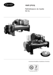
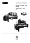
19XR
Positive Pressure Storage System
50/60 Hz
Installation, Operating, and
Maintenance Instructions
o
SAFETY CONSIDERATIONS
Positive pressure storage systems are designed to
provide safe and reliable service when operated
within design specifications. When operating this
equipment, use good judgment and safety precautions to avoid damage to equipment and property
or injury to personnel.
Installation, start-up, and servicing of this equipment can be hazardous due to system pressures,
electrical components, and equipment location
(roofs, elevated structures, etc.). Only trained,
qualified installers and service technicians should
install, start up, and service this equipment.
Be sure you understand and follow the procedures
and safety precautions contained in this guide.
DANGER
Failure to follow these procedures will result in severe personal injury or death.
DO NOT VENT refrigerant relief valves within a building.
Outlet from rupture disc or relief valve must be vented outdoors in accordance with the latest edition of ASHRAE 15
(American Society of Heating, Refrigerating, and Air Conditioning Engineers). The accumulation of refrigerant in an
enclosed space can displace oxygen and cause
asphyxiation.
PROVIDE adequate ventilation in accordance with
ASHRAE 15, especially for enclosed and low overhead
spaces. Inhalation of high concentrations of vapor is harmful and may cause heart irregularities, unconsciousness, or
death. Misuse can be fatal. Vapor is heavier than air and
reduces the amount of oxygen available for breathing.
Product causes eye and skin irritation. Decomposition
products are hazardous.
DO NOT USE OXYGEN to purge lines or to pressurize a
machine for any purpose. Oxygen gas reacts violently with
oil, grease, and other common substances.
NEVER EXCEED specified test pressures, VERIFY the
allowable test pressure by checking the instruction literature and the design pressures on the equipment nameplate.
DO NOT USE air for leak testing. Use only tracer gases
and dry nitrogen.
DO NOT VALVE OFF any safety device.
BE SURE that all pressure relief devices are properly
installed and functioning before operating any machine.
WARNING
Failure to follow these procedures may result in personal
injury or death.
DO NOT USE TORCH to remove any component. System
contains oil and refrigerant under pressure.
To remove a component, wear protective gloves and goggles and proceed as follows:
a. Shut off electrical power to unit.
b. Recover refrigerant to relieve all pressure from system using both high-pressure and low pressure ports.
c. Traces of vapor should be displaced with nitrogen
and the work area should be well ventilated. Refrigerant in contact with an open flame produces toxic
gases.
d. Cut component connection tubing with tubing cutter
and remove component from unit. Use a pan to catch
any oil that may come out of the lines and as a gage
for how much oil to add to the system.
e. Carefully unsweat remaining tubing stubs when necessary. Oil can ignite when exposed to torch flame.
DO NOT USE eyebolts or eyebolt holes to rig machine
sections or the entire assembly.
DO NOT work on high-voltage equipment unless you are a
qualified electrician.
DO NOT WORK ON electrical components, including
control panels, switches, starters, or oil heater until you are
sure ALL POWER IS OFF and no residual voltage can
leak from capacitors or solid-state components.
LOCK OPEN AND TAG electrical circuits during servicing. IF WORK IS INTERRUPTED, confirm that all circuits are deenergized before resuming work.
AVOID SPILLING liquid refrigerant on skin or getting it
into the eyes. USE SAFETY GOGGLES. Wash any spills
from the skin with soap and water. If any enters the eyes,
IMMEDIATELY FLUSH EYES with water and consult a
physician.
NEVER APPLY an open flame or live steam to a refrigerant cylinder. Dangerous overpressure can result. When
necessary to heat refrigerant, use only warm (110 F [43 C])
water.
DO NOT REUSE disposable (nonreturnable) cylinders or
attempt to refill them. It is DANGEROUS AND ILLEGAL. When cylinder is emptied, evacuate remaining gas
pressure, loosen the collar and unscrew and discard the
valve stem. DO NOT INCINERATE.
(Warnings continued on next page.)
Manufacturer reserves the right to discontinue, or change at any time, specifications or designs without notice and without incurring obligations.
Catalog No. 531-984
Printed in U.S.A.
Form 19XR-6SI
Pg 1
313
5-04
Replaces: 19XB-1SI
WARNING
CAUTION
CHECK THE REFRIGERANT TYPE before transferring
refrigerant to the machine. The introduction of the wrong
refrigerant can cause damage or malfunction to this
machine.
Operation of this equipment with refrigerants other than
those cited herein should comply with ASHRAE 15 (latest
edition). Contact Carrier for further information on use of
this machine with other refrigerants.
ENSURE that refrigerant is only pumped to or stored in
tanks that are ASME (American Society of Mechanical
Engineers) certified for the pressures appropriate to the
refrigerant being handled.
DO NOT ATTEMPT TO REMOVE fittings, covers, etc.,
while machine is under pressure or while machine is running. Be sure pressure is at 0 psig (0 kPa) before breaking
any refrigerant connection.
CAREFULLY INSPECT all relief devices, rupture discs,
and other relief devices AT LEAST ONCE A YEAR. If
machine operates in a corrosive atmosphere, inspect the
devices at more frequent intervals.
DO NOT ATTEMPT TO REPAIR OR RECONDITION
any relief device when corrosion or build-up of foreign
material (rust, dirt, scale, etc.) is found within the valve
body or mechanism. Replace the device.
DO NOT install relief devices in series or backwards.
USE CARE when working near or in line with a compressed spring. Sudden release of the spring can cause it
and objects in its path to act as projectiles.
DO NOT re-use compressor oil or any oil that has been
exposed to the atmosphere. Dispose of oil per local codes
and regulations.
DO NOT leave refrigerant system open to air any longer
than the actual time required to service the equipment. Seal
circuits being serviced and charge with dry nitrogen to prevent oil contamination when timely repairs cannot be
completed.
CONTENTS
Page
SAFETY CONSIDERATIONS . . . . . . . . . . . . . . . . . . . . 1,2
INTRODUCTION . . . . . . . . . . . . . . . . . . . . . . . . . . . . . . . . 2,3
INSTALLATION . . . . . . . . . . . . . . . . . . . . . . . . . . . . . . . . 3-10
Complete Pre-Installation Checks . . . . . . . . . . . . . . . . 3
• IDENTIFY UNIT
• INSPECT SHIPMENT
Mount the Pumpout Unit . . . . . . . . . . . . . . . . . . . . . . . . . 3
• MOUNTING ON THE CHILLER
• FLOOR MOUNTING
Rig the Storage Tank . . . . . . . . . . . . . . . . . . . . . . . . . . . . . 4
Make Piping Connections . . . . . . . . . . . . . . . . . . . . . . . . 6
• INSTALL VENT PIPING TO RELIEF DEVICES
Make Electrical Connections . . . . . . . . . . . . . . . . . . . . . 6
CONTROLS AND COMPONENTS . . . . . . . . . . . . . . . . 11
Pumpout Unit . . . . . . . . . . . . . . . . . . . . . . . . . . . . . . . . . . . 11
• CONTROLS
• SAFETY CONTROL SETTINGS
• COMPRESSOR
• CONDENSER
• OIL SEPARATOR
• SUCTION AND DISCHARGE VALVES
Storage Tank . . . . . . . . . . . . . . . . . . . . . . . . . . . . . . . . . . . . 11
• DRAIN VALVE
• DUAL RELIEF VALVES
• PRESSURE GAGE
• LEVEL GAGE
OPERATION . . . . . . . . . . . . . . . . . . . . . . . . . . . . . . . . . . 11-15
Overview . . . . . . . . . . . . . . . . . . . . . . . . . . . . . . . . . . . . . . . . 11
• REFRIGERANT TRANSFER
• TRANSFERRING LIQUID REFRIGERANT FROM
THE CHILLER COOLER TO THE CHILLER
CONDENSER OR PUMPOUT STORAGE TANK
• TRANSFERRING LIQUID REFRIGERANT FROM
THE CHILLER CONDENSER OR PUMPOUT
STORAGE TANK TO THE CHILLER COOLER
• DISTILLING THE REFRIGERANT
Pumpout and Refrigerant Transfer Procedures . . 12
• OPERATING THE PUMPOUT UNIT
• TO READ REFRIGERANT PRESSURES
• POSITIVE PRESSURE CHILLERS WITH STORAGE
TANKS
• CHILLERS WITH ISOLATION VALVES
• DISTILLING THE REFRIGERANT
MAINTENANCE. . . . . . . . . . . . . . . . . . . . . . . . . . . . . . . 15,16
Pumpout Compressor Oil Charge . . . . . . . . . . . . . . . 15
Storage Tank . . . . . . . . . . . . . . . . . . . . . . . . . . . . . . . . . . . . 16
Ordering Replacement Parts . . . . . . . . . . . . . . . . . . . . 16
TROUBLESHOOTING. . . . . . . . . . . . . . . . . . . . . . . . . . . . 16
CAUTION
Failure to follow these procedures may result in personal
injury or damage to equipment.
EQUIPMENT should be operated by certified personnel
only.
DO NOT STEP on refrigerant lines. Broken lines can whip
about and cause personal injury and damage to the
machine.
DO NOT climb over a machine. Use platform, catwalk, or
staging. Follow safe practices when using ladders.
USE MECHANICAL EQUIPMENT (crane, hoist, etc.) to
lift or move inspection covers or other heavy components.
Even if components are light, use such equipment when
there is a risk of slipping or losing your balance.
BE AWARE that certain automatic start arrangements
CAN ENGAGE THE STARTER. Open the disconnect
ahead of the starter in addition to shutting off the machine
or pump.
USE only repair or replacement parts that meet the code
requirements of the original equipment.
DOUBLE-CHECK that coupling nut wrenches, dial indicators, or other items have been removed before rotating
any shafts.
DO NOT LOOSEN a packing gland nut before checking
that the nut has a positive thread engagement.
PERIODICALLY INSPECT all valves, fittings, and piping
for corrosion, rust, leaks, or damage.
DO NOT MIX REFRIGERANT from chillers that use different compressor oils. Compressor damage can result.
(Cautions continued in next column.)
INTRODUCTION
The 19XR Positive Pressure Storage (PPS) System has been
designed to help owners and operators of positive pressure
chillers store HFC-134a refrigerant during service and repair
2
INSTALLATION
work. The 19XR system conserves this refrigerant and prevents the release of excessive amounts of refrigerant into the
atmosphere. The proper use of this equipment minimizes the
loss of HFCs.
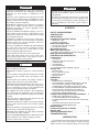
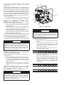
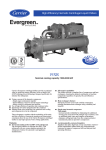
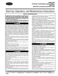
The 19XR PPS system shown in Fig. 1 consists of a pumpout unit mounted on a storage tank. The pumpout unit is
offered as a free-standing unit that can be used with chillers
that have an existing storage tank or with chillers that have isolation valves that permit built-in refrigerant storage.
The 19XR PPS systems are factory tested and certified to
the American Society of Mechanical Engineers (ASME) pressure vessel code. The tanks are constructed of certified steel
and are pressure rated at 185 psig (1276 kPa). The PPS storage
tank is equipped with dual relief valves for proper venting per
ASHRAE 15 (American Society of Heating, Refrigeration, and
Air Conditioning Engineers) guidelines. An automatic level
switch is prewired to the control circuit to ensure proper storage levels.
The 19XR pumpout unit is a complete, hermetic, compact
unit that consists of:
• a hermetic reciprocating compressor with a direct-drive
motor
• a water-cooled refrigerant condenser
• an oil separator
• suction and discharge valves to control refrigerant flow
• prewired safety and control devices.
Complete Pre-Installation Checks
IDENTIFY UNIT — Identify the assembly number (Table 1)
printed on the pumpout unit and storage tank nameplates.
Check this information against the job requirements. Fig. 1
shows the PPS system and its major components. Refer to
Tables 2 and 3 for physical data.
INSPECT SHIPMENT — Inspect unit for damage before
removing unit from shipping conveyance. If unit appears damaged, it should be inspected by a shipping inspector before
removal. File a claim with the shipping company if shipment is
damaged or incomplete. The manufacturer is not responsible
for damage incurred during transit.
Check all components. Notify the supplier immediately if
any item is missing. To prevent loss or damage, leave all parts
in their original package until they are needed.
Mount the Pumpout Unit — The pumpout unit, if
purchased separately, may be mounted directly on the chiller or
it may be floor mounted.
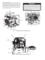
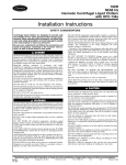
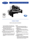
MOUNTING ON THE CHILLER — See instructions provided with the chiller for mounting the pumpout unit. A typical
chiller mount is shown in Fig. 2.
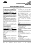
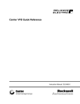
FLOOR MOUNTING — Select a ventilated and accessible
area, free of traffic or other hazards. Remove and discard the
4 angle supports at the base of the pumpout unit and bolt the
unit to the floor through the holes at the base of the pumpout
unit. Special isolation is unnecessary. Contact surface and
dimensions for the pumpout unit are given in Fig. 3.
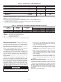
Table 1 — Positive Pressure System Assembly Numbers (R-134a)
PUMPOUT
SYSTEM
ARRANGEMENT
NUMBER
19XR04027401
19XR04027402
19XR04027403
19XR04027501
19XR04027502
19XR04027503
19XR04026801
19XR04026802
19XR04026803
19XR14017801
19XR14017802
19XR14017803
19XR34017801
19XR34017802
19XR34017803
19XR44017801
19XR44017802
19XR44017803
19XR54017801
19XR54017802
19XR54017803
19XR64017801
19XR64017802
19XR64017803
19XR74017801
19XR74017802
19XR74017803
19XR84017801
19XR84017802
19XR84017803
LRA
RLA
PUMPOUT UNIT
ASSEMBLY NUMBER
COMPRESSOR MOTOR
(V-Ph-Hz)
MAXIMUM
RLA
LRA
STORAGE TANK
19XR04026501
19XR04026502
19XR04026503
19XR04026501
19XR04026502
19XR04026503
19XR04026501
19XR04026502
19XR04026503
19XR04026501
19XR04026502
19XR04026503
19XR04026501
19XR04026502
19XR04026503
19XR04026501
19XR04026502
19XR04026503
19XR04026501
19XR04026502
19XR04026503
19XR04026501
19XR04026502
19XR04026503
19XR04026501
19XR04026502
19XR04026503
19XR04026501
19XR04026502
19XR04026503
208/230-3-50/60
460-3-60
400-3-50
208/230-3-50/60
460-3-60
400-3-50
208/230-3-50/60
460-3-60
400-3-50
208/230-3-50/60
460-3-60
400-3-50
208/230-3-50/60
460-3-60
400-3-50
208/230-3-50/60
460-3-60
400-3-50
208/230-3-50/60
460-3-60
400-3-50
208/230-3-50/60
460-3-60
400-3-50
208/230-3-50/60
460-3-60
400-3-50
208/230-3-50/60
460-3-60
400-3-50
15.8
7.8
7.8
15.8
7.8
7.8
15.8
7.8
7.8
15.8
7.8
7.8
15.8
7.8
7.8
15.8
7.8
7.8
15.8
7.8
7.8
15.8
7.8
7.8
15.8
7.8
7.8
15.8
7.8
7.8
105.0
52.0
52.0
105.0
52.0
52.0
105.0
52.0
52.0
105.0
52.0
52.0
105.0
52.0
52.0
105.0
52.0
52.0
105.0
52.0
52.0
105.0
52.0
52.0
105.0
52.0
52.0
105.0
52.0
52.0
28 cu ft (0.8 cu m)
28 cu ft (0.8 cu m)
28 cu ft (0.8 cu m)
52 cu ft (1.5 cu m)
52 cu ft (1.5 cu m)
52 cu ft (1.5 cu m)
Free-standing
Free-standing
Free-standing
Unit-mounted, frame 1
Unit-mounted, frame 1
Unit-mounted, frame 1
Unit-mounted, frame 2 or 3
Unit-mounted, frame 2 or 3
Unit-mounted, frame 2 or 3
Unit-mounted, frame 4
Unit-mounted, frame 4
Unit-mounted, frame 4
Unit-mounted, frame 5
Unit-mounted, frame 5
Unit-mounted, frame 5
Unit-mounted, frame 6
Unit-mounted, frame 6
Unit-mounted, frame 6
Unit-mounted, frame 7
Unit-mounted, frame 7
Unit-mounted, frame 7
Unit-mounted, frame 8
Unit-mounted, frame 8
Unit-mounted, frame 8
NOTES:
1. All storage vessels are 185 psig (1276 kPa) designs per the ASME (American Society of Mechanical Engineers) Boiler Pressure Vessel Code, Section VIII Division 1.
2. All units above are shipped with a 15 psig (103 kPa) nitrogen charge.
3. Nominal horsepower for all pumpout units is 3.0.
LEGEND
— Locked Rotor Amps
— Rated Load Amps
3
Rig the Storage Tank — The complete 19XR system
WARNING
can be rigged as a single assembly. See the rigging instructions
on the label attached to the assembly. Also refer to the rigging
guide (Fig. 4), physical data in Tables 2 and 3, and contact
surface and dimensions for the complete system in Fig. 5. Lift
the assembly only from the 4 points indicated in the rigging
guide. Each rigging cable must be capable of supporting the
entire weight of the assembly.
CONTROL
PANEL
VALVE
2
Lifting the assembly from points other than those specified may result in serious damage to the assembly and
personal injury. Rigging equipment and procedures must
be adequate for assembly. See Tables 2 and 3 for weights.
(These weights are broken down into pumpout unit and
storage tank weights. For the complete assembly weight,
add all components together.)
FRAME
ASSEMBLY
CONTACTOR
TERMINAL
STRIP
FUSES
VALVE
3
VALVE
4
COMPRESSOR
OIL
HEATER
TRANSFORMER
VALVE
5
19XR CONTROL BOX (INTERIOR)
ENTERING
WATER
LEAVING
WATER
OIL
SEPARATOR
CONDENSER
19XR PUMPOUT UNIT
Fig. 1 — 19XR Positive Pressure Storage System
COMPRESSOR
CONTROL
BOX
VALVE
ASSEMBLY
CONDENSER
OIL
SEPARATOR
Fig. 2 — 19XR Pumpout Unit: Typical Chiller Mount
4
SWITCH
28.45
(723)
VAPOR CONNECTIONS
1/2" MALE FLARE
24.75
(629)
HIGH PRESSURE SWITCH
3.25
(83)
WATER CONNECTIONS
3/4" FNPT
OIL SEPARATOR
CONTROL PANEL
VACUUM SWITCH
COMPRESSOR
ELECTRICAL
CONNECTION
LOCATION
23.00
(584)
18.13
(461)
13.12
(333)
11.59
(294)
9.74
(247)
8.21
(209)
4.25
(108)
1.00 (25)
CONDENSER
(2X) 1.82
(33)
7.94
(202)
9.50
(241)
2.88
(73)
4.58
(116)
13.25
(337)
9.48
(250)
19.00
(438)
OIL SIGHTGLASS
MOUNTING HOLES
OIL FILL FITTING
10.50
(267)
ELECTRICAL CONNECTION OPTION LIST
TRADE
SIZE
1/ s
2
3/ s
4
1s
11/ 4s
Dimensions in inches (millimeters).
QTY
1
1
1
1
LOCATIO
N
TOP
BOTTOM
MIDDLE
MIDDLE
Fig. 3 — Pumpout Unit Contact Surfaces and Dimensions
NOTES:
1. Each chain must be capable of supporting the entire weight of the machine.
2. Minimum chain length:
28 ft3 (0.79 m3) tank — 10c-0s (3098 mm)
52 ft3 (1.47 m3) tank — 15c-6s (4724 mm)
CENTER OF GRAVITY
OVERALL DIMENSIONS
DIMENSIONS
(APPROX.)
ft-in. (mm)
ft-in. (mm)
APPROX.
A
B
C
D
E
28 cu ft
4-91/8
1-77/8
10-5
2-43/4
4-41/4
(0.8 cu m)
(1451)
(505)
(3175)
(730)
(1327)
52 cu ft
6-115/8
1-83/4
14-111/4 2-81/2
4-81/4
(1.5 cu m)
(2124)
(527)
(4553)
(826)
(1429)
STORAGE
TANK
SIZE
Fig. 4 — Rigging Guide
5
EMPTY
WEIGHT
lb (kg)
2,385
(1082)
3,415
(1549)
Table 2 — Physical Data — 19XR Pumpout Unit
Pumpout Unit Weight*
Pumpout Condenser Water Flow Rate
Pumpout Condenser Water Pressure Drop
Maximum Entering Condenser Water Temperature
Maximum Leaving Condenser Water Temperature
Relief Valve
Condenser Pressure Rating
Refrigerant Side
Waterside
lb (kg)
gpm (L/s)
psig (kPa)
F (C)
F (C)
psig (kPa)
ENGLISH
164
7-9
0.3
85
100
235
SI
(75)
(.45-.58)
(2.0)
(29)
(37)
(1620)
psig (kPa)
psig (kPa)
450
450
(3102)
(3102)
*The pumpout unit weight includes the compressor/condenser, control box, and the oil separator.
NOTES:
1. The motor is hermetic with thermal protection.
2. The control box is mounted and wired with an ON/OFF/AUTO. switch according to NEMA 1 (National
Electrical Manufacturing Association).
3. The starter contactor is located in the control box. The overloads on the motor are wired and the
internal disconnect switch is supplied by the customer.
Table 3 — 19XR Storage Tank Rated Dry Weight and Refrigerant Capacity
SIZE
cu ft (cu m)
TANK OD
in. (mm)
DRY WEIGHT*
lb (kg)
28 (0.8)
52 (1.5)
24.00 (610)
27.25 (692)
2334 (1059)
3414 (1549)
MAXIMUM REFRIGERANT CAPACITY lb (kg)
ASHRAE/ANSI 15
UL 1963
R-134a
R-134a
1860 (844)
1716 (778)
3563 (1616)
3286 (1491)
LEGEND
ANSI
— American National Standards Institute
ASHRAE — American Society of Heating, Refrigeration,
and Air Conditioning Engineers
UL
— Underwriters’ Laboratories
*The above dry weight includes the pumpout unit weight of 164 lb (75 kg).
Make Piping Connections — Figure 6 represents typical pumpout unit/chiller piping connections. Standard connections for 1/2-in. OD copper tubing are provided. Install the
field-supplied FPT tee with pipe plug in the piping as shown in
Fig. 6. This tee is used for refrigerant charging.
NOTE: If any field piping runs exceed 50 ft in length, use
7/ -in. OD copper tubing to minimize pressure drop.
8
Pumpout unit water piping connections are shown in Fig. 6.
Both connections are 3/4-in. NPT (female). A shutoff valve
should be installed in the water line. Provide a means for blowing water from the condenser coil at winter shutdown to
prevent freeze-up damage. Refer to the Job Data for water
piping particulars.
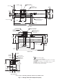
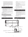
INSTALL VENT PIPING TO RELIEF DEVICES — The
pumpout storage tank is factory-equipped with relief devices.
Refer to Fig. 5 and Table 4 for size and location of the relief
devices. Vent the relief devices to the outdoors in accordance
with ANSI/ASHRAE 15 Safety Code (latest edition) for
Mechanical Refrigeration and all other applicable codes.
Pumpout unit relief devices are set to relieve at 235 psig
(1620 kPa). Storage tank relief devices are set to relieve at
185 psig (1276 kPa).
1. If relief devices are manifolded, the cross-sectional area
of the relief pipe must at least equal the sum of the areas
required for individual relief pipes.
2. Provide a pipe plug near outlet side of each relief device
for leak testing. Provide pipe fittings that allow vent piping to be disconnected periodically for inspection of valve
mechanism.
3. Piping to relief devices must not apply stress to the
device. Adequately support piping. A length of flexible
tubing or piping near the device is essential on springisolated machines.
4. Cover the outdoor vent with a rain cap and place a condensation drain at the low point in the vent piping to prevent water build-up on the atmospheric side of the relief
device.
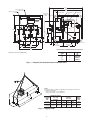
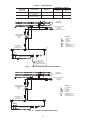
Make Electrical Connections — See nameplate on
compressor of pumpout unit and Table 1 for motor electrical
data. Wire unit according to the diagram inside the control box.
Figure 7 is the wiring schematic for a complete system that
includes the 19XR storage tank and the pumpout unit. Fig. 8 is
the wiring schematic for the pumpout unit. Use this schematic
for installations that do not include an auxiliary pumpout
storage tank.
NOTE: Use copper conductors only.
DANGER
Refrigerant discharged into confined spaces can displace
oxygen and cause asphyxiation.
6
2’-6"
[762mm]
3/8" MALE FLARE
RELIEF VALVE CONN.
LEVEL GAGE
0’-9"
[229 mm]
TYPICAL
1/2" DIA. K.O.
ELECTRICAL CONN.
(PUMPOUT POWER)
0’-5 1/2"
[140mm]
2’-8 1/2"
[826 mm]
(2) 1" NPT RELIEF
VALVE OUTLET (SEE FIELD
INSTALLATION NOTES)
PRESSURE GAGE
1’-7"
[483mm]
2’-0 5/8"
[625mm]
1’-4 1/4"
[413 mm]
0’-5 7/8"
[149mm]
5’-0 1/2"
[1537mm]
14’-4 1/2"
[4381mm]
TOP VIEW
3/4" NPT
PUMPOUT CONDENSER
WATER OUTLET CONN.
1/2" MALE FLARE
VAPOR CONN.
3/4" NPT
PUMPOUT CONDENSER
WATER INLET CONN.
ELECTRICAL SERVICE
ACCESS SPACE
20 3/4" X 8 3/4" X 4 1/2"
(BOTH SIDES)
VAPOR
3’ - 8 1/2 "
[1130mm]
3’ - 8 3/4"
[1137mm]
3’ - 4 1/2"
[1029mm]
3’ - 1 7/16"
[951mm]
1" NPT
LIQUID CONN.
2’ - 10 1/8"
[867mm]
2’ - 5 1/4"
[742mm]
0’ - 9 7/8"
[249mm]
0’ - 9 "
[229mm]
TYPICAL
6’ - 11 5/8"
[2124mm]
7’ - 2 1/4"
[2191mm]
0’ - 3 3/8"
[86mm]
14’ - 11 1/4"
[4553mm]
FRONT VIEW
52 CU. FT. [1.47 CU. METER]
STORAGE TANK WITH PUMPOUT UNIT
1’ - 0 3/4"
[324mm]
0’ - 0 15/16"
[202mm]
(FARSIDE)
NOTES:
1.
Denotes center of gravity.
2. Dimensions in [ ] are in millimeters.
3. The weights and center of gravity values given are for an empty
storage tank.
4. For additional information on the pumpout unit, see certified
drawings.
5. Conduit knockout is located on the side of the control box.
6. Storage tank weight: 3414 lb (1549 kg).
3/8" MALE FLARE
RELIEF VALVE CONN.
0’ - 2 3/4"
[70mm]
1/2" DIA. K.O.
ELECTRICAL CONN.
(PUMPOUT POWER)
(FAR SIDE)
4’ - 3 1/4"
[1302mm]
4’ - 8 1/4"
[1429mm]
4’ - 1"
[1225mm]
1’ - 8 3/4"
[527mm]
0’ - 3 1/4"
[83mm]
0’ - 10"
[254mm]
LEFT SIDE VIEW
52 CU FT [1.5 CU METER] STORAGE TANK WITH PUMPOUT UNIT
Fig. 5 — Storage Tank with Pumpout Unit
7
3/8" MALE FLARE
RELIEF VALVE CONN.
2’- 5 3/4"
[756mm]
LEVEL GAGE
0’ - 9 "
[229mm]
TYPICAL
1/2" DIA. K.O.
ELECTRICAL CONN.
(PUMPOUT POWER)
0’ - 5 1/2"
[140mm]
2’ - 4 3/4 "
[730mm]
(2) 1" NPT RELIEF
VALVE OUTLET (SEE FIELD
INSTALLATION NOTES)
PRESSURE GAGE
2’ - 0 3/8"
[619mm]
1’ - 7 "
[483mm]
5’ - 0 1/4 "
[1530mm]
1’ - 2 3/8 "
[365mm]
0’ - 5 7/8 "
[149mm]
9’ - 10 "
[2997mm]
TOP VIEW
3/4" NPT
PUMPOUT CONDENSER
WATER OUTLET CONN.
1/2" MALE FLARE
VAPOR CONN.
3/4" NPT
PUMPOUT CONDENSER
WATER INLET CONN.
ELECTRICAL SERVICE
ACCESS SPACE
20 3/4" X 8 3/4" X 4 1/2"
(BOTH SIDES)
VAPOR
3’- 4 7/8"
[1038mm]
3’- 4 5/8"
[1032mm]
2’- 9 9/16"
[852mm]
3’- 1 1/4"
[946mm]
1" NPT
LIQUID CONN.
2’- 9 7/8"
[860mm]
0’- 9 7/8"
[249mm]
2’- 5"
[737mm]
0’- 9"
[229mm]
TYPICAL
4’- 9 1/2"
[1451mm]
0’- 3 1/2"
[89mm]
6’- 4 3/16"
[1935mm]
10’- 5 "
[3175mm]
FRONT VIEW
1’-0 3/4"
[324mm]
0’- 7 15/16"
[202mm]
(FARSIDE)
28 CU.FT. [.79 CU. METER]
STORGE TANK WITH PUMPOUT UNIT
3/8" MALE FLARE
RELIEF VALVE CONN.
0’- 2 3/4"
[70mm]
NOTES:
1/2" DIA. K.O.
ELECTRICAL CONN.
(PUMPOUT POWER)
(FAR SIDE)
1.
Denotes center of gravity.
2. Dimensions in [ ] are in millimeters.
3. The weights and center of gravity values given are for an empty
storage tank.
4. For additional information on the pumpout unit, see certified
drawings.
5. Conduit knockout is located on the side of the control box.
6. Storage tank weight: 2334 lb (1059 kg).
3’- 11 3/8"
[1203mm]
4’- 4 1/4"
[1327mm]
3’- 9"
[1143mm]
1’- 7 7/8"
[505mm]
0’- 3 1/4"
[83mm]
0’- 10"
[254mm]
LEFT SIDE VIEW
28 CU FT [0.8 CU METER] STORAGE TANK WITH PUMPOUT UNIT
Fig. 5 — Storage Tank with Pumpout Unit (cont)
8
PRESSURE RELIEF
VALVE
PRESSURE RELIEF
VALVE
TO TOP OF
CHILLER
COOLER
OR CONDENSER
TO TOP OF
CHILLER
COOLER
PUMPOUT
COMPRESSOR
SEE NOTE
#1
TO ADDITIONAL
CHILLERS
2
PUMPOUT
COMPRESSOR
OIL
SEPARATOR
3
2
WATER
CONNECTIONS
SERVICE VALVES
4
5
4
TO TOP OF
STORAGE TANK
TO TOP OF
CHILLER
CONDENSER
STORAGE TANK
VAPOR VALVE
TEE FOR
REFRIGERANT
CHARGING
FROM BOTTOM
OF STORAGE TANK
STORAGE TANK
LIQUID REFRIGERANT VALVE
WATER
CONNECTIONS
5
SEE NOTES
# 1 AND 2
TO TOP OF
STORAGE TANK
CHECK
VALVE
TEE FOR
REFRIGERANT
CHARGING
STORAGE TANK
VAPOR VALVE
FROM BOTTOM
OF STORAGE TANK
CHILLERS WITH ISOLATION VALVES
(WITH OR WITHOUT PUMPOUT STORAGE TANKS)
LEGEND
GENERAL PIPING CONNECTION SIZES
Factory-Supplied Tubing
SIZE (in.)
Flare (male)
3/ NPT (female)
4
3/ Flare (male)
8
1/
PUMPOUT
CONDENSER
3
STORAGE TANK
LIQUID REFRIGERANT VALVE
CHILLERS WITHOUT ISOLATION VALVES
CONNECTION
Refrigerant Transfer Connections
Condenser Water Cooling Connectors
Safety Relief Head Pumpdown
OIL
SEPARATOR
SERVICE VALVES
SEE NOTES
# 1 AND 2
CHECK
VALVE
TO BOTTOM OF
COOLER AND
CHILLER
CONDENSER
SEE NOTE
#1
PUMPOUT
CONDENSER
Field-Supplied Tubing
2
Field-Supplied Tubing (Multiple Chillers)
Service Valve (Factory Supplied)
Service Valve (Field Supplied)
NOTES:
1. The field-supplied tubing is to be 1/2-in. OD tubing (min.) and
must be arranged and supported to avoid stresses on the equipment, transmission of vibrations, and interference with routine
access during the reading, adjusting, and servicing of the equipment. If the distance from the chiller to the pumpout unit is over
50 ft, then 7/8-in. OD tubing (min.) must be used. Provisions
should be made for adjustment in each plane of the tubing and
for both periodic and major servicing of the equipment. Special
care must be taken so that the safety head does not experience
tubing strain. Vent the safety head per ASHRAE 15 (American
Society of Heating, Refrigeration, and Air Conditioning Engineers), latest revision.
2. The tubing and valve from the storage tank to the pumpout compressor is factory supplied when the unit is factory mounted.
Fig. 6 — Typical Pumpout Unit/Chiller Connection Schematic
9
Table 4 — Relief Devices
STORAGE
TANK SIZE
cu ft (cu m)
RELIEF VALVE
OUTLET SIZE
1 in. NPT
Female Connector
1 in. NPT
Female Connector
28 (0.8)
52 (1.5)
REQUIRED “C” FACTOR
lb air
Kg air
min
min
QUANTITY
C
2 CL
C
2 CL
C
2 CL
2
31.4
14.2
2
52.3
23.7
MTR-1
GND
L1
8
FU2
H4
X1
X2
CRANKCASE HEATER
240-600v
27-40 WATT
COPELAND PN 081-0031-03
C
FU
GND
HTR
MTR
NC
OL
SS
0.5A
FU3
CONTROL POWER H1
TRANSFORMER
XFMR-1
69 VA
HIGH PRESSURE
SAFETY
NC OPEN > 185psig
2
HTR-1
7
0.25A
FU1
0.25A
L2
PUMP OUT
COMPRESSOR
WHT
X2
1
LEGEND
— Contactor
— Fuse
— Ground
— Heater
— Motor
— Normally Closed
— Overload
— Selector Switch
6
55-1
OFF
AUTO ON
2
2
3
4
LOW PRESSURE CONTROL
NC OPEN < 7 psia (-15.7 in. HG)
CLOSE > 9 psia (-11.6 in. HG)
5
ORN
C
X2
RED
HIGH LEVEL
GAGE ALARM
(NC-OPEN AT 90%
STORAGE TANK LEVEL)
WHT
Fig. 7 — 19XR Pumpout System Wiring Schematic
C
2 CL
C
2 CL
C
2 CL
MTR-1
GND
L1
8
2
FU2
H4
X1
X2
HTR-1
CRANKCASE HEATER
240-600v
27-40 WATT
C
FU
GND
HTR
MTR
NC
OL
SS
0.5A
FU3
CONTROL POWER H1
TRANSFORMER
XFMR-1
69 VA
HIGH PRESSURE
SAFETY
NC OPEN > 185psig
7
0.25A
FU1
0.25A
L2
PUMP OUT
COMPRESSOR
1
X2
6
55-1
OFF
AUTO ON
2
2
3
LOW PRESSURE CONTROL
NC OPEN < 7 psia {-15.7 in. HG}
CLOSE > 9 psia {-11.6 in. HG}
4
5
C
X2
Fig. 8 — Pumpout Unit Wiring Schematic
10
LEGEND
— Contactor
— Fuse
— Ground
— Heater
— Motor
— Normally Closed
— Overload
— Selector Switch
CONTROLS AND COMPONENTS
OPERATION
Figure 1 shows the major components of the PPS system.
Overview — Transferring refrigerant from one vessel to
another is accomplished by using either gravity or pressure
differential. A difference in elevation between 2 vessels results
in a gravity flow of liquid; a difference in pressure forces the
liquid from one vessel to the other. The latter method requires
lowering the pressure in one vessel. If there is liquid in that
vessel, its temperature must be lowered, and the pressure in the
other vessel must be simultaneously increased.
Under most circumstances, creating the pressure differential
is not a difficult process. Some applications, such as ice
storage, outdoor installations, or installations with high temperature differentials between the storage tank and the chiller may
require additional consideration. In some instances, it may be
necessary to add auxiliary heat to one of the vessels or to insulate the storage tank at job sites where high ambient temperature or sun load make it difficult to reduce the temperature and
pressure in the tank. Outdoor installations must have a roof or
cover over the storage tank to ensure that the pressure in the
tank does not exceed the chiller relief pressure setting.
REFRIGERANT TRANSFER — When refrigerant is being
evacuated from the chiller cooler or condenser vessels, any
liquid refrigerant left in a vessel will flash off, lowering the
temperature in that vessel enough to freeze the fluid (usually
water) flowing through the cooler or condenser tubes. This
event, called tube freeze-up, can cause extensive damage to the
chiller; therefore, all liquid refrigerant must be removed from a
vessel before evacuation of refrigerant vapor is started. If all
the liquid cannot be removed, then the cooler water and condenser water pumps must be operated throughout the process
of evacuating refrigerant vapor to keep fluid moving through
the cooler and condenser tubes.
TRANSFERRING LIQUID REFRIGERANT FROM THE
CHILLER COOLER TO THE CHILLER CONDENSER
OR PUMPOUT STORAGE TANK — Chiller and pumpout
unit valves are set to permit the pumpout compressor to
discharge refrigerant vapor into the cooler vessel, lowering
pressure in the condenser vessel/storage tank. The pressure
differential forces liquid from the cooler vessel into the condenser vessel/storage tank. After all the liquid is transferred, the
refrigerant vapor remaining in the cooler vessel can be drawn
off by reducing pressure in the chiller and discharging the
vapor through the pumpout unit condenser into the condenser
vessel/storage tank.
NOTE: The pumpout selector switch can be placed in On
or Automatic mode. In Automatic mode, the compressor will
shut off automatically once the suction pressure drops to 7 psia
or 15 in. Hg vacuum (51.7 kPa absolute). In On mode, the unit
will continue to pumpout regardless of the suction (vacuum)
pressure.
TRANSFERRING LIQUID REFRIGERANT FROM THE
CHILLER CONDENSER OR PUMPOUT STORAGE
TANK TO THE CHILLER COOLER — Chiller and pumpout unit valves are set to increase pressure in the chiller
condenser vessel/storage tank and to reduce pressure in the
cooler vessel. Pressure in the cooler vessel is lowered to correspond to a saturated refrigerant liquid temperature 2° F (1.1° C)
above the freezing temperature of the liquid circulating through
the chiller cooler/condenser tubes (34 F [1.1 C] for water). The
valves are set so that the pressure in the cooler vessel is lower
than that of the condenser vessel/storage tank, forcing the liquid into the cooler vessel.
NOTE: The pumpout selector switch can be placed in On or
Automatic mode. In Automatic mode, the compressor will shut
off automatically once the suction pressure drops to 7 psia or
15 in. Hg vacuum (51.7 kPa absolute). In On mode, the unit
will continue to pumpout regardless of the suction (vacuum)
pressure.
Pumpout Unit — The pumpout unit consists of a
hermetic reciprocating compressor, a water cooled refrigerant
condenser, an oil separator, and prewired safety and control devices. The pumpout unit comes equipped with a 4-way transfer
valve manifold to interconnect both liquid and vapor transfer
and to pressurize the chiller during transfer of refrigerant from
chiller to storage tank.
CONTROLS — The pumpout unit has the following controls:
manual/off/automatic selector switch, transformer, .25 amp
fuses for the primary side of the transformer, .5 amp fuse for
the secondary side of the transformer, contactor, terminal strip,
high pressure cutout switch and low pressure switch.
SAFETY CONTROL SETTINGS — The pumpout unit highpressure switch (Fig. 1) is set to open at the settings listed in
Table 5. The switch setting is checked by operating the pumpout
condenser and slowly throttling the pumpout condenser water.
When the selector switch is in the Automatic position, the
pumpout will cycle on a low pressure/vacuum switch. This
switch will shut down the pumpout compressor when suction
pressure reaches 7 ± 1.5 psia or 15 ± 3 in. Hg vacuum
(51.7 kPa absolute). When the selector switch is in the On
position, the pumpout compressor will continue to run until
refrigerant vapor flow is so low that the compressor motor
overheats. At this time the compressor motor overload will
shut off the compressor. This is NOT recommended.
Table 5 — High Condition Pressure Switch Settings
REFRIGERANT
R-134a
HIGH PRESSURE SWITCH
Cutout
Cut-in
185 ± 10 psig
140 ± 10 psig
(1276 ± 69 kPa)
(965 ± 69 kPa)
COMPRESSOR — The hermetic compressor assembly
comes equipped with internal thermal protection on the motor
and a self-regulating crankcase heater.
CONDENSER — The water-cooled condenser is a brazed
plate heat exchanger. During transfer, it condenses refrigerant
vapor to liquid.
OIL SEPARATOR — The pumpout unit includes an in-line
oil separator to remove oil that becomes mixed with refrigerant
and returns the oil to the compressor.
SUCTION AND DISCHARGE VALVES — The pumpout
unit comes with a 4-way transfer valve manifold to interconnect both liquid and vapor transfer and to pressurize the chiller
during transfer of refrigerant from chiller to storage tank or
from one chiller vessel to another.
Storage Tank — The storage tank is rated for positive
pressure refrigerants under ASME Section VIII pressure vessel
codes with a minimum of 185 psig (1276 kPa) rating. The tank
components include:
DRAIN VALVE — Located at its lowest point of drain with a
minimum of 1 in. NPT.
DUAL RELIEF VALVES — Two relief valves and a 3-way
shut-off valve.
PRESSURE GAGE — A 30 in. Hg vacuum -0-400 psig
(101-0-2760 kPa) compound pressure gage.
LEVEL GAGE — Liquid level gage (magnetically coupled
dial type) with electronic shut-off at 90% liquid capacity.
WARNING
During transfer of refrigerant into and out of the pumpout
storage tank, carefully monitor the storage tank level gage.
Do not fill the tank more than 90% of capacity to allow for
refrigerant expansion. Overfilling may result in damage to
the tank and personal injury. For maximum refrigerant
capacity, refer to Table 3.
11
NOTE: During this operation, maintain water circulation
through the chiller cooler and condenser vessels to prevent
tube freeze-up.
DISTILLING THE REFRIGERANT — Refrigerant vapor is
transferred from the chiller cooler vessel or pumpout storage
tank through the pumpout condenser, condensed to a liquid,
and pumped to the chiller condenser vessel. During this operation, water circulation must be maintained in the pump-out
condenser. Refrigerant impurities left in the chiller cooler vessel or storage tank are then drained off. This operation can take
from 4 to 14 hours, depending on the type and amount of refrigerant being distilled.
The Pumpout and Refrigerant Transfer Procedures section
gives step-by-step instructions on performing these operations.
CONTROL
PANEL
VALVE
2
FRAME
ASSEMBLY
VALVE
3
VALVE
4
COMPRESSOR
OIL
HEATER
VALVE
5
Pumpout and Refrigerant Transfer Procedures — Three possibilities are available:
ENTERING
WATER
1. If there are no isolation valves on the chiller, a complete
pumpout system with a pumpout storage tank and pumpout unit is needed.
2. Whether or not isolation valves are available on the chiller, the refrigerant can be pumped to and isolated in a
pump-out storage tank by using the pumpout unit.
3. If isolation valves are available on the chiller, the refrigerant can be pumped to either the cooler vessel or the condenser vessel using the pumpout unit.
NOTE: Oil should be visible in the pumpout compressor sight
glass under all operating conditions and during shutdown. If oil
is low, add oil as described in the Maintenance section.
The following procedures describe how to transfer refrigerant from one vessel to another and how to evacuate the chiller.
LEAVING
WATER
CONDENSER
OIL
SEPARATOR
Fig. 9 — Pumpout Unit
Transfer Refrigerant from Pumpout Storage Tank to Chiller
WARNING
During transfer of refrigerant into and out of the 19XR
storage tank, carefully monitor the storage tank level gage.
Do not fill the tank more than 90% of capacity to allow for
refrigerant expansion. Overfilling may result in damage to
the tank and personal injury.
1. Equalize refrigerant pressure.
a. Turn on chiller water pumps and monitor chiller
pressures.
b. Close pumpout and storage tank valves 2, 4, 5, and
10, and close refrigerant charging valve 7; open
chiller isolation valve 11 and any other chiller isolation valves, if present.
c. Open pumpout and storage tank valves 3 and 6;
open chiller valves 1a and 1b.
CAUTION
Do not mix refrigerants from chillers that use different
compressor oils. Compressor damage can result. The
pumpout oil separator comes pre-charged with 13 oz of
ISO viscosity 220 POE (Polyol Ester) oil. The pumpout
compressor is approved for use with ISO viscosity 220
POE oil or ISO viscosity 68 POE oil. The pumpout compressor is also factory precharged with oil.
VALVE
CONDITION
OPERATING THE PUMPOUT UNIT — Connect all refrigerant lines to pumpout as shown in Fig. 6.
TO READ REFRIGERANT PRESSURES — During pumpout or leak testing:
1. Refer to the display on the chiller control center to determine refrigerant-side pressures and low (soft) vacuum.
Use a quality vacuum indicator or manometer to measure
evacuation and dehydration and to ensure the desired
range and accuracy.
2. Attach a 30 in. Hg vacuum -0-400 psi (101-0-2760 kPa)
compound gage to the storage tank to determine its
pressure.
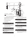
POSITIVE PRESSURE CHILLERS WITH STORAGE
TANKS — In the Valve/Condition tables that accompany
these instructions, the letter “C” indicates a closed valve.
Figures 9 and 10 show the locations of the valves.
1a
1b
2
C
3
4
C
5
C
6
7
C
10
C
11
d. Gradually crack open valve 5 to increase chiller
pressure to 35 psig (241 kPa). Slowly feed refrigerant to prevent freeze-up.
e. Open valve 5 fully after the chiller pressure rises
above the freezing point of the refrigerant. Let the
storage tank and chiller pressure equalize. Open
refrigerant charging valve 7 and storage tank
charging valve 10 to let liquid refrigerant drain
into the chiller.
VALVE
CONDITION
1a
1b
2
C
3
4
C
5
6
7
10
11
6
7
10
11
2. Transfer remaining refrigerant.
a. Close valve 5 and open valve 4.
VALVE
CONDITION
WARNING
Always run chiller cooler and condenser water pumps and
always charge or transfer refrigerant as a gas when chiller
vessel pressure is less than 35 psig (241 kPa). Below these
pressures, liquid refrigerant flashes into gas, resulting in
extremely low temperatures in the cooler/condenser tubes
and possibly causing tube freeze-up.
12
1a
1b
2
C
3
4
5
C
1b
SERVICE VALVE
CHILLER
CONDENSER
VESSEL
1a
SERVICE VALVE
CHILLER
COOLER
VESSEL
COOLER 11
REFRIGERANT
ISOLATION
VALVE
TEE FOR
CHARGING
PRESSURE
RELIEF SAFETY
VALVE
STORAGE
TANK LIQUID
VALVE
7
10
OIL
SEPARATOR
REFRIGERANT
CHARGING
VALVE
PUMPOUT
COMPRESSOR
= SERVICE VALVE ON
CHILLER (FIELD
SUPPLIED)
= SERVICE VALVE ON
PUMPOUT UNIT
= MAINTAIN AT LEAST 2 FT (610mm) CLEARANCE AROUND
STORAGE TANK FOR SERVICE AND OPERATION WORK.
PUMPOUT
CONDENSER
2
3
4
5
PUMPOUT
CONDENSER
WATER SUPPLY
AND RETURN
6
STORAGE TANK
VAPOR VALVE
Fig. 10 — Valve Locations for 19XR Pumpout Unit With 19XB Storage Tank
b. Turn off the pumpout condenser water, and turn
on the pumpout compressor in manual mode to
push liquid refrigerant out of the storage tank.
Monitor the storage tank level until the tank is
empty.
c. Close refrigerant charging valves 7 and 10.
d. Turn off the pumpout compressor.
e. Turn off the chiller water pumps.
f. Close valves 3 and 4.
g. Open valves 2 and 5.
VALVE
CONDITION
1a
1b
2
3
C
4
C
5
6
7
C
10
C
b. Slowly open valve 5 and refrigerant charging
valves 7 and 10 to allow liquid refrigerant to drain
by gravity into the storage tank.
VALVE
CONDITION
1a
C
1b
C
2
C
3
C
4
C
5
C
6
C
7
C
10
C
VALVE
CONDITION
11
1a
1b
2
C
3
4
C
5
C
6
7
C
10
C
2
C
3
4
C
5
6
7
10
11
1a
1b
2
3
C
4
C
5
6
7
10
11
b. Run the pumpout compressor in automatic mode
until vacuum switch is satisfied and compressor
stops.
VALVE
CONDITION
1a
1b
2
3
C
4
C
5
6
7
C
10
C
11
10
C
11
c. Turn off the pumpout compressor.
3. Remove any remaining refrigerant.
a. Turn on chiller water pumps.
b. Turn on pumpout condenser water.
c. Place valves in the following positions:
11
l. Turn off pumpout condenser water.
Transfer the Refrigerant from Chiller to Pumpout Storage
Tank
1. Equalize refrigerant pressure.
a. Valve positions:
VALVE
CONDITION
1b
2. Transfer the remaining liquid.
a. Turn off pumpout condenser water. Place valves in
the following positions:
h. Turn on pumpout condenser water.
i. Run the pumpout compressor in manual mode
until the storage tank pressure reaches 5 psig
(34 kPa), 18 in. Hg vacuum (41 kPa absolute).
j. Turn off the pumpout compressor.
k. Close valves 1a, 1b, 2, 5, and 6.
VALVE
CONDITION
1a
VALVE
CONDITION
1a
1b
2
C
3
4
5
C
6
7
C
d. Run the pumpout compressor until the chiller
pressure reaches 35 psig (241 kPa); then, shut off
the pumpout compressor. Warm chiller condenser
water will boil off any entrapped liquid refrigerant
and chiller pressure will rise.
11
13
c. Equalize the refrigerant in the chiller cooler and
condenser.
d. Turn off chiller water pumps and pumpout condenser water supply.
e. Turn on pumpout compressor to push liquid out of
the chiller cooler vessel.
f. When all liquid has been pushed into the chiller
condenser vessel, close the cooler refrigerant isolation valve (11).
g. Turn on the chiller water pumps.
h. Turn off the pumpout compressor.
2. Evacuate gas from chiller cooler vessel.
a. Close pumpout valves 2 and 5; open valves 3
and 4.
e. When chiller pressure rises to 40 psig (276 kPa),
turn on the pumpout compressor until the pressure
again reaches 35 psig (241 kPa), then, turn off the
pumpout compressor. Repeat this process until the
chiller pressure no longer rises; then, turn on the
pumpout compressor and pump out until the
chiller pressure reaches 18 in. Hg vacuum (41 kPa
absolute). This can be done in On or Automatic
mode.
f. Close valves 1a, 1b, 3, 4, and 6.
VALVE
CONDITION
1a
C
1b
C
2
C
3
C
4
C
5
C
6
C
7
C
10
C
11
g. Turn off the pumpout condenser water.
4. Establish vacuum for service. To conserve refrigerant,
operate the pumpout compressor as described in Step 3e
until the chiller pressure is reduced to 18 in. Hg
vacuum (41 kPa absolute).
This operation can be done in Automatic or On mode.
In Automatic mode, the compressor will stop automatically at approximately 15 in. Hg vacuum (51 kPa
absolute).
CHILLERS WITH ISOLATION VALVES — The valves
referred to in the following instructions are shown in Fig. 9 and
11. Valve 7 remains closed.
VALVE
CONDITION
1a
1b
2
3
C
4
C
5
1b
2
C
3
4
VALVE
CONDITION
11
1a
C
1b
1b
C
2
C
3
C
4
C
SERVICE VALVE
CHILLER
CONDENSER
VESSEL
CHILLER
COOLER
VESSEL
COOLER 11
REFRIGERANT
ISOLATION
VALVE
7
REFRIGERANT
CHARGING
VALVE
PRESSURE
RELIEF SAFETY
VALVE
1a
SERVICE VALVE
OIL
SEPARATOR
= SERVICE VALVE ON
PUMPOUT UNIT
= SERVICE VALVE ON
CHILLER
5
C
11
C
b. Turn on pumpout condenser water.
c. Run pumpout compressor until the chiller cooler
vessel pressure reaches 18 in. Hg vacuum (41 kPa
absolute). Monitor pressures on the chiller control
panel and on refrigerant gages.
This operation can be done in Automatic or On
mode. In Automatic mode, the compressor will
stop automatically at approximately 15 in. Hg
vacuum (51 kPa absolute).
d. Close valve 1a.
e. Turn off pumpout compressor.
f. Close valves 1b, 3, and 4.
Transfer All Refrigerant to Chiller Condenser Vessel
1. Push refrigerant into chiller condenser vessel.
a. Turn on the chiller water pumps and monitor the
chiller pressure.
b. Valve positions:
VALVE
CONDITION
1a
PUMPOUT
CONDENSER
PUMPOUT
COMPRESSOR
2
3
4
5
PUMPOUT
CONDENSER
WATER SUPPLY
AND RETURN
Fig. 11 — Valve Locations for 19XR Pumpout Unit Without Storage Tank
14
5
C
11
C
8. Open chiller isolation valve 11 and any other isolation
valves, if present.
g. Turn off pumpout condenser water.
h. Turn off chiller water pumps and lock out chiller
compressor.
Transfer All Refrigerant to Chiller Cooler Vessel
1. Push refrigerant into the chiller cooler vessel.
a. Turn on the chiller water pumps and monitor the
chiller pressure.
b. Valve positions:
VALVE
CONDITION
1a
1b
2
3
C
4
C
5
VALVE
CONDITION
1a
1b
2
3
C
4
C
5
11
VALVE
CONDITION
1a
C
1b
C
2
C
3
C
4
C
5
C
11
C
VALVE
CONDITION
1a
1b
2
C
3
4
C
5
C
11
C
VALVE
CONDITION
1a
1b
2
C
3
4
C
5
4
C
5
C
11
1a
1b
2
C
3
4
C
5
C
6
7
C
10
C
11
1a
1b
2
3
C
4
C
5
6
7
C
10
C
11
1a
C
1b
C
2
C
3
C
4
C
5
C
6
C
7
C
10
C
11
4. Drain the contaminants from the bottom of the storage
tank into a container. Dispose of contaminants safely.
MAINTENANCE
Periodic maintenance is necessary to keep all components
functioning as designed. A maintenance log is recommended
to ensure a proper maintenance schedule is followed.
11
C
Pumpout Compressor Oil Charge — Use oil con-
4. Crack open valve 5, gradually increasing pressure in the
evacuated chiller vessel to 35 psig (241 kPa). Feed refrigerant slowly to prevent tube freeze-up.
5. Leak test to ensure chiller vessel integrity.
6. Open valve 5 fully.
VALVE
CONDITION
3
C
c. Turn on pumpout condenser water.
d. Run the pumpout compressor until the storage
tank pressure reaches 5 psig (34 kPa), 18 in. Hg
vacuum (41 kPa absolute) in Manual or Automatic
mode.
e. Turn off the pumpout compressor.
f. Close valves 1a, 1b, 2, 5, and 6.
g. Turn off pumpout condenser water.
h. Turn off pumpout condenser water.
i. Turn off chiller water pumps and lock out chiller
compressor.
Return Refrigerant to Normal Operating Conditions
1. Be sure that the chiller vessel that was opened has been
evacuated.
2. Turn on chiller water pumps.
3. Open valves 1a, 1b, and 3.
VALVE
CONDITION
2
C
d. Gradually crack open valve 5 to increase chiller
pressure to 35 psig (241 kPa). Slowly feed refrigerant to prevent freeze-up.
e. Open valve 5 fully after the chiller pressure rises
above the freezing point of the refrigerant. Let the
storage tank and chiller pressure equalize.
3. Transfer remaining refrigerant.
a. Close valve 3.
b. Open valve 2.
c. Turn on pumpout condenser water.
d. Run the pumpout compressor until the chiller condenser reaches 18 in. Hg vacuum (41 kPa absolute) in Manual or Automatic mode. Monitor
pressure at the chiller control panel and refrigerant
gages.
e. Close valve 1b.
f. Turn off pumpout compressor.
g. Close valves 1a, 2, and 5.
VALVE
CONDITION
1b
C
9. Turn off chiller water pumps.
DISTILLING THE REFRIGERANT
1. Transfer the refrigerant from the chiller to the pumpout
storage tank as described in the Transfer the Refrigerant
from Chiller to Pumpout Storage Tank section.
2. Equalize the refrigerant pressure.
a. Turn on chiller water pumps and monitor chiller
pressures.
b. Close pumpout and storage tank valves 2, 4, 5, and
10, and close chiller charging valve 7; open chiller
isolation valve 11 and any other chiller isolation
valves, if present.
c. Open pumpout and storage tank valves 3 and 6;
open chiller valves 1a and 1b.
c. Equalize the refrigerant in the chiller cooler and
condenser.
d. Turn off chiller water pumps and pumpout condenser water.
e. Turn on pumpout compressor to push refrigerant
out of the chiller condenser.
f. When all liquid is out of the chiller condenser,
close valve 11 and any other liquid isolation
valves on the chiller.
g. Turn off the pumpout compressor.
2. Evacuate gas from chiller condenser vessel.
a. Turn on chiller water pumps.
b. Make sure that pumpout valves 3 and 4 are closed
and valves 2 and 5 are open.
VALVE
CONDITION
1a
C
forming to Carrier specifications for centrifugal or screw compressor use. Oil requirements are listed in Table 6.
Monitor and adjust compressor oil level as often as
necessary. When replacing lost oil, add the same type of oil that
is used in the chiller being pumped out.
11
C
Table 6 — Pumpout Compressor Oil Requirements
7. Close valves 1a, 1b, 3, and 5.
REFRIGERANT
R-134a
15
ISO
VISCOSITY
68
220
CARRIER
SPECIFICATION NO.
PP47-31
PP47-32
The pumpout oil separator comes pre-charged with 13 oz of
ISO viscosity 220 POE (Polyol Ester) oil. The pumpout compressor is approved for use with ISO viscosity 220 POE oil or
ISO viscosity 68 POE oil. The pumpout compressor is also factory precharged with POE oil.
Oil should be visible in the pumpout compressor sight glass
both during operation and at shutdown. Always check the oil
level before operating the pumpout compressor. Before adding
or changing oil, relieve the refrigerant pressure through the access valves.
Relieve refrigerant pressure and add oil to the pumpout unit
as follows:
1. Close service valves 2 and 4.
2. Run the pumpout compressor in Automatic mode for one
minute or until the vacuum switch is satisfied and compressor shuts off.
3. Move the pumpout selector switch to OFF. Pumpout
compressor shell should now be under vacuum.
4. Oil can be added to the shell with a hand oil pump
through the access valve in the compressor base.
NOTE: Compressor access valve has a self-sealing fitting
which will require a hose connection with a depressor to open.
Storage Tank — To prevent moisture and contaminants
from entering the storage tank, maintain positive pressure in the
tank when not transferring refrigerant. Leak test the storage
tank periodically.
Ordering Replacement Parts — The following information must accompany an order for Carrier-specified parts:
• machine model number and serial number
• name, quantity, and part number of the part required
• delivery address and method of shipment
TROUBLESHOOTING
Information on troubleshooting for the PPS System is included in Table 7.
Table 7 — Troubleshooting
SYMPTOM
Compressor Does Not
Run
Compressor Cycles On
High-Pressure Control
Unit Operates Too Long
System Noises
Compressor Loses Oil
PROBABLE CAUSE
Main power line open
Loose terminal connection
Improperly wired controls
Low line voltage
Compressor motor defective
Seized compressor
High level gage alarm
High-pressure control erratic in action
Discharge valve partially closed.
Air in system
Condenser scaled.
Condenser water pump or fans not
operating.
Isolation valves partially open
Piping vibrations
Insufficient compressor oil
Leak in system
Plugged or stuck compressor oil return
check valve
Liquid refrigerant carries oil out of
compressor
Motor shutdown on internal thermal protection high temperature cutout.
REMEDY
Replace fuse or reset circuit breaker.
Check connections.
Check wiring and rewire.
Check line voltage; determine location of voltage drop.
Check motor winding for open or short. Replace compressor if
necessary.
Replace compressor.
Check refrigerant level and remove excess.
Check capillary tube for pinches. Set control as required.
Open valve.
Purge system.
Clean condenser.
Start pump or fans.
Close valves.
Support piping as required. Check for loose pipe connectors.
Add oil.
Locate and repair leak.
Repair or replace valve.
Check to ensure only refrigerant vapor enters compressor suction line. Add oil as necessary.
High temperature cutout should reset within 120 minutes.
Copyright 2004 Carrier Corporation
Manufacturer reserves the right to discontinue, or change at any time, specifications or designs without notice and without incurring obligations.
Catalog No. 531-984
Printed in U.S.A.
Form 19XR-6SI
Pg 16
313
5-04
Replaces: 19XB-1SI