1
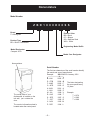
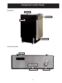
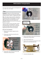
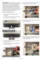
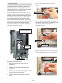
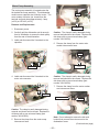
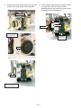
GE Consumer & Industrial
TECHNICAL SERVICE GUIDE
Monogram 18-In. Built-In
Compact Dishwasher
MODEL SERIES:
ZBD1800K
PUB # 31-9123 7/04
–1–
IMPORTANT SAFETY NOTICE
The information in this service guide is intended for use by
individuals possessing adequate backgrounds of electrical,
electronic, and mechanical experience. Any attempt to repair a
major appliance may result in personal injury and property
damage. The manufacturer or seller cannot be responsible for the
interpretation of this information, nor can it assume any liability in
connection with its use.
WARNING
To avoid personal injury, disconnect power before servicing this
product. If electrical power is required for diagnosis or test
purposes, disconnect the power immediately after performing the
necessary checks.
RECONNECT ALL GROUNDING DEVICES
If grounding wires, screws, straps, clips, nuts, or washers used
to complete a path to ground are removed for service, they must
be returned to their original position and properly fastened.
GE Consumer & Industrial
Technical Service Guide
Copyright © 2004
All rights reserved. This service guide may not be reproduced in whole or in part,`
in any form, without written permission from the General Electric Company.
–2–
TABLE OF CONTENTS
Bottom Door Seal ................................................................................................. 19
Component Locator Views ..................................................................................... 7
Control Panel Features .......................................................................................... 6
Detergent/Rinse Module ....................................................................................... 15
Dishwasher Components ................................................................................... 10
Dishwasher Tub Seal .......................................................................................... 20
Door Assembly ..................................................................................................... 17
Door Panel ........................................................................................................... 14
Door Switch and Latch Assembly ........................................................................ 12
Drain Pump Assembly .......................................................................................... 24
Fill Funnel ............................................................................................................. 21
Heating Element ................................................................................................... 20
Illustrated Parts Catalog ....................................................................................... 40
Introduction ............................................................................................................ 4
Motor Pump Assembly ........................................................................................ 25
Nomenclature ........................................................................................................ 5
Pressure Switch .................................................................................................. 23
Schematic ............................................................................................................ 39
Side Panels .......................................................................................................... 16
Specifications ......................................................................................................... 4
Static Dry System ................................................................................................. 13
Sump Assembly ................................................................................................... 27
Timer .................................................................................................................... 10
Troubleshooting .................................................................................................... 29
Troubleshooting Checklist .................................................................................... 34
Troubleshooting the Door Switch ......................................................................... 29
Troubleshooting the Heating Element ................................................................... 30
Troubleshooting the Timer .................................................................................... 31
Troubleshooting the Wash Pump Motor ............................................................... 32
Troubleshooting the Water Fill Valve ..................................................................... 32
Warranty ............................................................................................................... 46
Washability Complaints ........................................................................................ 38
Water Valve .......................................................................................................... 22
–3–
Introduction
The new Monogram 18" Built-In Compact Dishwasher has a size that
allows the unit to fit in areas as small as 18 inches (45.72 cm) wide, 22
inches (55.88 cm) long, and 34 inches (86.36 cm) high. It is compact in
size, yet delivers the performance of larger units. With a low power
usage, this product model meets ENERGY STAR® guidelines for
energy efficiency.
The Monogram 18" Built-In Compact Dishwasher has two wash levels,
a HEAVY WASH cycle, NORMAL WASH cycle, LIGHT WASH cycle,
CHINA CRYSTAL cycle, and a RINSE ONLY cycle.
Specifications
Electrical
Rating
120 Volts, 60 Hz ±10%
Separate Circuit
4.5 to 5.5 Amps
Motor (HP)
1/5
Motor (Amps)
1 ±10%
Heater Wattage – Wash/Dry
465 ±10%
Total Amps (Load Rated)
5 ±10%
Component Resistance (OHMS)
Timer Motor
1460 ±10%
Heating Element
31 ±5%
Pump Motor Windings
Drain
27 ±10%
Wash (Blue to Red)
47 ±10%
Run Windings – Main
22 ±10%
(Blue to Black)
Water Valve Solenoid
1140 ±5%
Total Amps (Load Rated)
5 ±10%
Water Supply
Suggested Minimum
120 °F to 150 °F
Incoming Water Temperature
(49 °C to 66 °C)
Sump Water Temperature
145 °F ±5 °F
With Outer Door In Place
(63 °C ±3 °C)
Water Charge
2.54 to 3.27 Quarts
(2.4 to 3.1 Liters)
Pressure
20 Min./120 Max. (PSI)
138 Min./827 Max. (kPa)
Connection (NPT)
3/8 In. (0.95 cm)
Consumption (Total)
4.7 to 6.1 Gallons
(17.8 to 23.1 Liters)
Water Valve Flow Rate
1.8 ±14%
(GPM)
(6.81 LPM ±14%)
Water Circulation Rate (GPM) 10 ±10%
(37.85 LPM ±10%)
Water Fill Time (Seconds)
30 (±1)
–4–
Nomenclature
Model Number
Z B D 1 8 0 0 K 0 0 S S
Brand
Z = Monogram
Exterior Color
BB = Black
CC = Bisque
SS = Stainless Steel
WW = White
Product Type
BD = Built-In Dishwasher
Engineering Model Suffix
Model Designator
Compact 18-in.
Model Year Designator
Nomenclature
Serial Number
The first two characters of the serial number identify
the month and year of manufacture.
Example:
AG123456S = January, 2001
The serial plate of your
dishwasher is located on the
tub wall, just outside the
door.
The service information sheet is
located under the control panel.
A - JAN
D - FEB
F - MAR
G - APR
H - MAY
L - JUN
M - JUL
R - AUG
S - SEP
T - OCT
V - NOV
Z - DEC
–5–
2005 - H
2004 - G
2003 - F
2002 - D
2001 - A
2000 - Z
1999 - V
1998 - T
1997 - S
1996 - R
1995 - M
1994 - L
The letter designating
the year repeats every
12 years.
Example:
T = 1974
T = 1986
T = 1998
Control Panel Features
Static Vent
Door Latch Switch
Control Timer
Control Timer:
START
Close the dishwasher door and turn the control timer knob to the desired setting.
Water fill begins and approximately 30 seconds later, the wash action begins.
HEAVY WASH
This cycle is for heavily soiled dishes and glassware.
NORMAL WASH
This cycle is for medium-soiled dishes and glassware.
LIGHT WASH
This cycle is for everyday dishes and glassware.
CHINA CRYSTAL This cycle is specifically designed for lightly soiled china and crystal.
RINSE ONLY
Door Latch
Switch:
For rinsing partial loads that will be washed later. Do not use detergent with this cycle.
Automatically shuts off the dishwasher whenever the dishwasher door is opened. The
dishwasher will not resume operation until the door is closed.
–6–
Component Locator Views
Front View
Insulation
Control Panel
Side Panel
Access Panel
Control Panel View
Static Vent
Door Latch Switch
–7–
Control Timer
Interior View (With Racks)
Top Rack
Bottom Rack
Detergent/Rinse Module
Static Dry Vent
Detergent/Rinse Module Compartment View
Detergent
Compartment
Sight Glass
Rinse Agent Cap
Compartment Lid
–8–
Interior View of Basin (With Racks Removed)
Right Side View
(Side Panel and Insulation Removed)
Spray Arm
Door Tension Spring
Fill Funnel
Heating Element
Pressure
Switch Hose
Fill Hose
Filter Assembly
Clamp Nut
Microfilter
Bottom View (Looking Up)
Sump
Drain Pump
Motor Pump
Assembly
Capacitor
–9–
Dishwasher Components
Throughout this manual, features and appearance
may vary from your model.
Timer
WARNING: Always turn off the electric power
supply before servicing any electrical component,
making ohmmeter checks, or replacing any parts.
Note: All voltage checks should be made with a
voltmeter having a full-scale range of 130 volts or
higher. After service is completed, be sure all
safety grounding circuits are complete, all
electrical connections are secure, and all access
panels are in place.
Mark the inside of
the hole threads with
a felt-tip marker.
The timer allows the user to select the various
cleaning cycles of the dishwasher. The timer
controls all stages of each cycle. All electrical
functions can be traced on the charts and
diagrams provided in this service manual.
Removal and Installation
1. Disconnect the electric supply from the
dishwasher.
2. Remove the control timer knob from the
control panel cover.
4. Remove the bottom screw and mark the hole
threads with a felt-tip marker.
5. Open the dishwasher door.
6. Remove the 6 screws that connect the control
panel cover to the dishwasher door.
Control Timer Knob
3. Remove the top screw and mark the hole
threads with a felt-tip marker.
7. Close the dishwasher door.
– 10 –
8. Release the door latch and allow the control
panel cover to hang against the dishwasher
door.
Note: When installing the timer, it is important to
align the threaded holes (A) and (B), marked in
steps 3 and 4, with holes (A) and (B) in the control
panel
Threaded Hole (A)
Timer
Threaded Hole (B)
Control Panel
Align the threaded holes
marked in steps 3 and 4
with the holes in the
control panel.
9. Disconnect the ground wire from the timer.
10. Disconnect the connectors. (Refer to minimanual or schematic diagram on page 39 for
reconnection.)
B
A
White Connector
– 11 –
Door Switch and Latch Assembly
The door switch and latch assembly is located on
the door assembly behind the control panel cover.
The dishwasher will not operate until the door is
closed, the latch engages the door catch (holding
the door firmly against the seal), and the normally
open contacts of the double-pole, single-throw
door safety switch are closed.
7. Remove the 4 screws that connect the door
switch mounting bracket to the control panel
cover.
8. Pull the door switch assembly down far
enough so that the door latch cup clears the
door latch mounting bracket.
Switch
Removal and Installation
1. Disconnect the electric supply from the
dishwasher.
Bracket
Assembly
2. Open the dishwasher door.
Caution: Place a cloth or cardboard between the
control panel and the dishwasher door to prevent
marring the door.
Cup
Pull
3. Remove the 6 screws that connect the control
panel cover to the dishwasher door. (See
Timer, step 6.)
9. Remove the door switch from the door latch
mounting bracket.
4. Close the dishwasher door.
5. Release the door latch and allow the control
panel cover to hang against the dishwasher
door.
Note: There are 6 terminals on the door switch.
The top 2 terminals (1) and (2) are not used. The
middle 2 terminals are marked (3) and (4). The
bottom 2 terminals are marked (5) and (6).
10. Inspect the door latch spring. Make sure the
door latch flap fits properly in the door latch
flap hole. If the spring is misaligned, broken,
or missing, insert a new spring in the spring
post holes.
6. Tag and disconnect the 4 wire terminals from
the door switch.
Flap
Spring
– 12 –
6. Inspect the gasket on the channel assembly.
If the gasket shows obvious signs of wear or
damage, replace the channel assembly.
Static Dry System
The static dry system operates through a vent
located in the control panel. The vent allows hot
air to exit the dishwasher tub and gradually
remove moisture.
Removal
1. Open the dishwasher door.
Gasket
2. Remove the 6 screws that connect the control
panel cover to the dishwasher door. (See
Timer, step 6.)
3. Release the door latch and allow the control
panel cover to hang against the dishwasher
door.
Installation
4. Remove the static vent channel cover and
assembly as shown below. Inspect the cover
for hard water/lime deposits or debris, and
clean if necessary.
1. Insert the static vent channel through the
static vent door hole.
Hole
Channel
Cover
Channel
5. Inspect the o-ring. If the o-ring shows obvious
signs of wear or damage, replace the channel
assembly.
2. Install the static vent cover to the static vent
channel, and position the control panel cover
on the dishwasher door.
O-Ring
(Continued next page)
– 13 –
Door Panel
Note: Make sure the edge of the control panel
cover is flush with the edge of the door.
3. Align the screw holes on the control panel with
the screw holes on the dishwasher door.
The door panel covers the door to the dishwasher
and protects the detergent/rinse module
electronics.
Removal
1. Disconnect the electric supply from the
dishwasher.
Cover
2. Open the dishwasher door.
3. Remove the 6 screws and the door panel
from the door assembly. Do not remove the 6
screws that hold the control panel cover to the
door assembly.
Make sure the edge
of the control panel
cover is flush with
the edge of the door.
4. Install the 6 screws that connect the control
panel cover to the dishwasher door.
Door Panel
– 14 –
Detergent/Rinse Module
The detergent rinse module automatically
dispenses both the detergent and the rinse agent
at the appropriate times. The module is activated
twice during a wash cycle.
When activated for the second time in a cycle, the
lever lifts the connecting rod by the notch, lifting
the rinse dispenser plunger (4) and releasing the
rinse agent. When deactivated, the lever returns
to its original starting position.
The first time the module is activated (1), the lever
slides up the right-hand path of the connecting
rod.
4
Removal and Replacement
1. Disconnect the electric supply from the
dishwasher.
1
2. Remove the Door Panel.
This action moves the cover catch (2) and
releases the detergent cover.
3. Remove the foam insulation.
2
Insulation
Cover
When deactivated (3), the lever resets to rest
under the notch in the center of the connecting
rod.
4. Disconnect the 2 terminals from the
detergent/rinse module.
3
(Continued next page)
– 15 –
5. Remove the 3 screws and top mounting
bracket.
Side Panels
Removal
Bracket
1. Disconnect the electric supply from the
dishwasher.
2. Carefully pull the dishwasher out from its
installation.
3. Remove the screws from the top and back of
each dishwasher side panel (16 screws total).
Open the door and remove the 4 screws
securing the panels to the inside door frame.
6. Remove the 3 screws and bottom mounting
bracket.
Bracket
7. Remove the detergent/rinse module from door
assembly.
4. Lay the dishwasher on its back. Remove the 4
screws securing the toekick to the dishwasher
and remove the toekick.
Detergent/Rinse Module
– 16 –
5. Remove the single screw just above and to
the side of each front leveling leg.
6. Disconnect the ground wire from the Timer.
7. Disconnect the green and white multipin
connectors from the Timer.
8. Disconnect the 4 terminal lugs from the Door
Switch and Latch Assembly.
Door Latch
Timer
9. Remove the Door Panel.
10. Disconnect the 2 terminal lugs from the
Detergent/Rinse Module switch.
Door Assembly
Removal and Replacement
1. Disconnect the electric supply from the
dishwasher.
2. Carefully pull the dishwasher out from its
installation.
3. Remove the 6 screws that connect the control
panel cover to the dishwasher door. (See
Timer, step 6.)
4. Close the dishwasher door.
Caution: Place a cloth or cardboard between the
control panel and the dishwasher door to prevent
marring the door.
11. Remove the bolt, nut, and ground wire from
the door.
12. Pull the wire harness from the door.
5. Release the door latch and allow the control
panel cover to hang against the dishwasher
door.
Wire Harness
Bolt, Nut, and
Ground Wire
(Continued next page)
– 17 –
Note: There is a door hinge assembly on both
the left and right sides of the dishwasher. Both
door hinge assemblies must be removed in order
to remove the door. The procedure to remove the
right-side door hinge assembly is outlined in steps
13 through 24. The left-side door hinge assembly
removal is identical.
18. Open the dishwasher door approximately 30
degrees.
19. Lift the bottom hinge arm up from the bottom
hinge, far enough to expose the hook.
Open
13. Remove the 4 screws, access panel, and toekick panel from the dishwasher.
14. Remove the side panels. (See Side Panels.)
15. Mark the position of the spring bolt key in the
mounting bracket with a felt-tip marker.
Lift
Key
Bracket
Hook
Hinge
16. Pull the spring and spring bolt key from the
mounting bracket.
17. Lift the bottom of the spring loop from the
hinge arm stud.
20. Close the dishwasher door.
Caution: The star washer is easily damaged
during removal and should not be reused. Order
a new set of star washers (part number:
WD01X10254).
21. Remove the star washer from the
dishwasher door hinge.
Loop
Stud
Caution: The
star washer is
easily damaged
and should not
be reused.
Star Washer
– 18 –
22. Remove the hinge pin from the dishwasher
door hinge.
Bottom Door Seal
The bottom door seal prevents water leakage.
The seal is fitted in a pinched metal groove at the
bottom of the dishwasher door.
Removal and Replacement
Pin
1. Remove the Door Panel.
2. Remove the Door Assembly (steps 13 through
22 only).
3. Grab one end of the bottom door seal and peel
it away from the pinched metal groove.
23. Repeat steps 15 through 22 to remove the
left-side door hinge assembly.
WARNING: The pinched metal groove is sharp.
Wear Kevlar gloves when removing or installing
the door seal. Failure to comply may result in
personal injury.
24. Remove the dishwasher door from the
dishwasher.
Pinched Metal
Groove
Tub Seal
Note: When installing the door seal, make sure it
is seated properly in the pinched metal groove.
Run your finger over the groove to make sure it is
smooth and even for a proper seal.
Make sure the seal is
properly seated in the
pinched metal groove.
– 19 –
Dishwasher Tub Seal
Heating Element
The dishwasher tub seal prevents water leakage.
The seal is fitted in a seal channel that lines the
rim of the dishwasher tub.
Removal and Replacement
The heating element maintains water temperature
during the wash and rinse cycles and heats the
air during the static dry cycle. (See Specifications
for heating element wattage ratings.)
To check operation, advance timer to the dry
cycle, set the selector switch for heated dry, and
close and latch the dishwasher door. Allow one or
two minutes before opening the dishwasher door
and note if heat is present.
1. Open the dishwasher door.
2. Grab one end of the dishwasher tub seal and
peel it away from the seal channel.
Removal and Replacement
1. Disconnect the electric supply from the
dishwasher.
2. Open the dishwasher door.
3. Remove the top and bottom dishwasher
racks.
Seal Channel
4. From underneath the dishwasher tub, locate
the wires leading to the heating element.
Tub Seal
5. Pull down the nylon covers, rubber wire
protectors, and plastic strain reliefs from the
wire terminals.
3. Reverse the above procedure to install.
Note: When installing the tub seal, make sure it
is seated properly in the seal channel. Run your
finger over the seal to make sure it is smooth and
even for a proper seal. A correctly installed gasket
will have both ends of the gasket equidistant from
the bottom of the tub.
2 Wire Covers
2 Wire Protectors
2 Strain Reliefs
Make sure the seal
is seated properly in
the seal channel.
6. Disconnect the 2 terminal lugs from the
heating element.
– 20 –
Fill Funnel
The fill funnel is mounted on the left side of the
tub. Its purpose is to provide a method of
supplying water for the wash and rinse cycles.
The air gap prevents the siphoning of wash water
from flowing back into the water supply system,
should the water pressure drop to less than
atmospheric pressure. The fill funnel also allows
air into the tub to permit air flow for dish drying.
Removal and Replacement
7. Remove the nut and ground wire.
8. Remove the lock-washer and spacer bracket.
1. Fold back the insulation surrounding the fill
funnel and air gap assembly.
2. Open the dishwasher door.
Spacer Bracket
Lock-washer
3. Rotate the fill funnel cap counterclockwise and
remove it from the fill funnel threads.
Ground Wire
Nut
Threads
Funnel Cap
Turn CCW
9. Release the 2 heating element clamps.
4. Loosen the clamp, disconnect the fill funnel
hose, and remove the fill funnel.
Clamp
Fill Funnel
Fill Funnel Hose
10. Lift up and remove the heating element from
the dishwasher.
Heating Element
Note: Make sure that the clear plastic air tube is
looped around that part of the fill funnel that
protrudes into the dishwasher tub and mates with
the fill funnel cap.
– 21 –
5. Remove the clamp and disconnect the tub fill
hose from the water valve assembly.
Water Valve
The water valve is timer controlled and solenoid
operated. The flow of water is controlled by a
rubber flow washer capable of maintaining a flow
rate of 1.8 ±14% gallons per minute (6.81 ±14%
liters per minute) with incoming water pressure of
20 to 120 PSI. The water valve is mounted to the
left hinge support of the dishwasher.
Tub Fill Hose
Valve Assembly
Removal and Replacement
Clamp
1. Disconnect the electric supply from the
dishwasher.
2. Remove the 4 screws, access panel, and toekick panel from the dishwasher.
6. Disconnect the 2 terminal lugs from the water
fill valve assembly.
Access Panel
Shown with access panel removed.
Toe-Kick Panel
7. Remove the 4 screws and water fill valve from
the mounting bracket. Retain the mounting
bracket and screws.
3. Disconnect the incoming water line from the
water fill valve port.
4. Remove the 2 screws and mounting bracket
from the dishwasher.
Mounting Bracket
Mounting Bracket
Port
Shown with water line removed.
– 22 –
5. Remove the capillary tube from the float
switch.
Pressure Switch
The pressure switch is located under the tub at
the right front corner. A clear plastic tube, the
pressure switch hose, runs from the float switch,
around the fill funnel, and to the sump.
As the dishwasher basin fills with water, the air
pressure in the pressure switch hose increases.
Normally, the timer regulates the amount of time
the water fill valve remains open. If the water fill
valve remains energized, the overfilling of the
basin increases the air pressure in the pressure
switch hose, causing the pressure switch to open
the circuit to the timer motor and closing the
circuit to the drain pump. The drain pump then
empties the water in the sump.
Pressure Switch Hose
6. Turn the float switch clockwise to align the
mounting tab vertically with the mounting hole,
and remove the float switch from the
dishwasher frame.
Right side of dishwasher
showing the path of the
pressure switch hose.
Turn
Mounting Tab
Fill Funnel
Mounting Hole
Pressure
Switch Hose
7. Label and disconnect the 3 terminal lugs from
the float switch, and remove the float switch.
Pressure Switch
3 Terminal Lugs
Removal and Replacement
1. Disconnect the electric supply from the
dishwasher.
2. Carefully pull the dishwasher out from its
installation.
3. Remove the 4 screws, access panel, and toekick panel from the dishwasher.
4. Remove the 10 screws and the right side
panel.
– 23 –
5. Remove the 2 bolts, lock-washers, and nuts.
Drain Pump Assembly
The drain pump assembly is located under the tub
at the right rear corner. The drain pump operates
on 120 VAC and is energized 60 seconds after the
wash pump shuts down, to remove any water in
the dishwasher sump. The drain pump forces the
water out the drain line. A check valve flapper on
the drain pump prevents the dirty water from
reentering the sump.
Removal and Replacement
1. Disconnect the electric supply from the
dishwasher.
2. Carefully pull the dishwasher out from its
installation.
3. Remove the 4 screws, access panel, and toekick panel from the dishwasher.
4. Remove the 10 screws and the right side
panel.
Caution: The clamp is easily damaged during
removal and should not be reused. Replace the
old clamp with a new universal clamp (part
number: WH1X2036).
6. Remove the clamp from the sump
interconnect hose.
7. Remove the drain pump from the sump
interconnect hose.
5. Remove the drain tube (not shown) from the
drain pump port.
Clamp
Port
Interconnect
Hose
Drain Pump
6. Label and disconnect the 2 terminal lugs from
the drain pump.
8. Remove and save the 2 screws, lockwashers, mounting bracket, and nut plate
from the drain pump.
Nut Plate
Mounting Bracket
2 Screws
2 Lock-washers
– 24 –
Motor Pump Assembly
The motor pump assembly is located under the
tub behind the sump assembly. This dishwasher
model uses a capacitor start induction motor. The
motor rotates clockwise (as viewed from the
terminal end) and draws approximately 1 amp
(±10%) at 120 VAC (±10%).
Clamp
Removal and Replacement
Interconnect
Hose
1. Disconnect power.
2. Carefully pull the dishwasher out far enough
from its installation to access the drain pump
from the rear of the dishwasher.
3. Label and disconnect the 2 terminals to the
capacitor.
Caution: The clamp is easily damaged during
removal and should not be reused. Replace the
old clamp with a new universal clamp (part
number: WH1X2036).
6. Remove the clamp from the motor main
conduit interconnect hose.
Clamp
Interconnect
Hose
Capacitor
4. Label and disconnect the 2 terminals to the
motor wire connector.
Caution: The clamp is easily damaged during
removal and should not be reused. Replace the
old clamp with a new universal clamp (part
number: WH1X2036).
7. Remove the clamp from the motor washer
arm interconnect hose.
Connector
Interconnect Hose
Clamp
Caution: The clamp is easily damaged during
removal and should not be reused. Replace the
old clamp with a new universal clamp (part
number: WH1X2036).
5. Remove the clamp from the motor sump
interconnect hose.
Note: Do not attempt to remove the bolt and
locknut that connect the motor mount to the
dishwasher frame.
(Continued next page)
– 25 –
8. Remove the screw and disconnect the ground
wire from the wash pump motor assembly.
9. Pull the motor mount back far enough to clear
the motor tab, work the motor from the
attaching hoses, and remove the motor pump
assembly from the dishwasher.
Ground Wire
Pull Out
Motor Tab
Motor Mount
Pull Out
As seen from rear
of dishwasher.
Motor Pump
Assembly
Bolt
Locknut
As seen from right side
of dishwasher.
– 26 –
Sump Assembly
The sump assembly consists of the filter
assembly, micro-filter, sump clamping nut, sump
gasket, and sump. The filter assembly prevents
large particles from reaching the micro-filter, and
the micro-filter prevents small particles from
reaching the sump. The filter assembly rests
above the sump and the micro-filter sits above the
sump basin. The clamping nut holds the sump
gasket and sump to the bottom of the dishwasher.
The filter assembly, microfilter, and sump
clamping nut are accessed from inside the
dishwasher. The sump gasket and sump are
located under the tub in front of the motor pump
assembly.
Removal and Replacement
7. Remove the clamp from the hose that
connects the sump to the drain pump
assembly.
Clamp
8. Open the dishwasher door and remove the
bottom rack (not shown).
9. Remove the filter assembly.
1. Disconnect power.
2. Carefully pull the dishwasher out from its
installation.
Filter
Assembly
3. Remove the 4 screws, access panel, and toekick panel from the dishwasher.
4. Remove the 10 screws and the right side
panel.
5. Remove the high-pressure switch hose from
the sump.
Shown with washer arm removed.
Pressure
Switch Hose
Sump
10. Remove the microfilter.
Microfilter
6. Remove the clamp from the interconnect
hose that connects the sump to the wash
pump motor.
Shown with washer arm removed.
Clamp
Interconnect
Hose
(Continued next page)
– 27 –
Note: The sump clamping nut turns
counterclockwise and may be difficult to remove.
It may be necessary to insert a screw driver or
other tool between the clamping nut tabs to
enable you to apply sufficient torque to break the
factory seal.
11. Remove the clamping nut.
Clamp
Nut
Tabs
12. Remove the sump gasket (not shown) and
sump.
– 28 –
Troubleshooting
WARNING: Always turn off the electric power
supply before servicing any electrical component,
making ohmmeter checks, or replacing any parts.
Note: All voltage checks should be made with a
voltmeter having a full-scale range of 130 volts or
higher. After service is completed, be sure all
safety grounding circuits are complete, all
electrical connections are secure, and all access
panels are in place.
Troubleshooting the Door Switch
The door switch can be tested using an
ohmmeter and the strip circuit.
1. Disconnect the electric supply from the
dishwasher.
2. Remove the wire leads from the door switch.
3. Use an ohmmeter to check the door switch for
continuity.
4. If the door switch is defective, remove it from
the latch assembly. If the door switch is good,
check to see if the timer is defective.
Door Switch Strip Circuit
PRESSURE
SWITCH
OPTIONAL
SWITCH
– 29 –
Troubleshooting the Heating Element
The heating element maintains water temperature
during the wash and rinse cycles and heats the air
during the static dry cycle. (See Specifications for
heating element wattage ratings.)
To check operation, advance timer to the dry cycle,
set the selector switch for heated dry, then close
and latch the dishwasher door. Allow one or two
minutes before opening the dishwasher door and
note if heat is present.
1. Disconnect the electric supply from the dishwasher.
2. Remove electrical connection from one side of
heating element and test continuity.
3. Measure the resistance of the heating element.
The resistance should be approximately 31 (±
5%) ohms.
Heating Element Strip Circuit
OPTIONAL
SWITCH
– 30 –
Timer Strip Circuit
Troubleshooting the Timer
PRESSURE
SWITCH
If the timer is suspected of faulty operation, refer
to the Timer Cycle Chart and Timer Strip Circuit
and proceed as follows:
1. Index the timer to the first increment of the
HEAVY WASH cycle. (This is a drain period
which activates the pump motor.)
2. If the pump motor fails to operate during the
first cycle increment block, check the electric
supply. If there is no electric supply, check the
door latch switch. If there is electric supply,
disconnect electric supply and check the
pump motor component resistance (see
Specifications, page 4).
3. If the pump motor does operate, let the timer
motor advance the timer through the drain
increment to determine if the timer motor and
drive train are fully operative.
4. Let the timer advance or index it forward to the
portion of the cycle in question.
5. If a component controlled by the timer fails to
function, as the timer advances through the
cycle, check for voltage at the timer terminals.
If the voltage is supplied to the component,
check the component resistance (see
Specifications, page 4).
OPTIONAL
SWITCH
With electric supply disconnected, continuity
through timer contacts, other controls, and wires
can be checked with an ohmmeter.
If the timer contacts fail to close in the sequence
shown on the timer cycle chart, are burned (have
resistance measurable with an ohmmeter), or
don't advance automatically, replace timer.
A4
A3
A9
B3
B9
A7
COLOR
VIO
FUNCTION
WASH PUMP
A2
A1
BU
R
INLET VALVE
DRAIN PUMP
A12
BK
BUS
B2
W
DISPENSER
B11
B12
BK
BR
WASH HEATING
DRYING HEATING
5
PROGRAM START
PROGRAMME START
SWITCH
F
E
O
X
X
O
CYCLE
POTS & PANS
POST&PAN
HEAVY WASH
NORMAL WASH
LIGHT WASH
CHINA CRYSTAL
RINSE & HOLD
RINSE&HOLD
DRY
HEAT DRY
COOL DRY
10
2
1
RINSE
6MIN.
15
RINSE
6MIN.
RINSE
6MIN.
25
30
5
4
3
20
RINSE
6MIN.
35
40
6
RINSE
6MIN.
– 31 –
WASH
24MIN.
RINSE
6MIN.
45
50
55
60
7
RINSE
14MIN.
DRY
HOT OR COOL
36MIN.
RESET
LOC
Pos
Timer Cycle Chart
Troubleshooting the Wash Pump Motor
Troubleshooting the Water Fill Valve
The wash pump motor does not start immediately
when the dishwasher cycle has started. The tub
will begin filling with water and the motor will start
approximately 40 seconds into the fill cycle. If the
motor hums, but will not start, make certain the
pump impeller is free from obstructions and the
motor shaft can turn freely. If the capacitor is
open or shorted, the motor will hum and will not
start. Check for 120 VAC (±10%) at the wash
pump motor terminals. Take the voltage
measurement while "under load" (as the motor is
trying to start). This will eliminate the possibility of
a poor wiring connection. If the 120 VAC (±10%)
is present and the motor will not start, the motor
will have to be replaced.
Wash Pump Motor Strip Circuit
PRESSURE
SWITCH
If the water fill valve is suspected of faulty
operation, refer to the strip circuit and proceed as
follows:
1. Disconnect the electric supply from the
dishwasher.
2. Remove screws securing bottom of service
panel.
3. Remove valve electrical leads and, using
ohmmeter, check resistance of solenoid. (See
Specifications, page 4, for correct ohms
reading.)
4. To check for proper mechanical operation of
the water valve, attach a separate 115-volt
grounded power source to the valve terminals
and metal frame of the dishwasher. Turn the
power on for a few seconds and then turn the
power off. If water flow does not stop within 2
seconds after turning the water valve off,
replace the water valve.
No Water To Tub
1. Be sure the main water supply and electric
power are turned on.
2. Remove both the service panel and the
toekick panel.
3. Advance timer to the fill position and latch the
door.
4. Start the dishwasher.
5. Use a voltmeter to check for voltage at the
water fill valve solenoid coil.
6. If voltage is present, disconnect power and
measure resistance of the water fill valve
solenoid coil. (See Specifications, page 4, for
correct ohms reading.) Replace the water
valve, if it is defective.
7. If the water fill valve is good, check the filter
screen and clean it, if necessary.
8. If there is no voltage present at the water fill
valve solenoid coil, disconnect power and
check continuity through the latch switch,
timer contacts, float switch, and wiring.
Repair wiring, as necessary.
Water Level Too Low
1. Turn on the dishwasher and allow the bottom
of the basin to fill with water. Listen for the
water fill cycle to stop and, when it does, open
the dishwasher door. The water level should
touch the heating element.
– 32 –
2. If the water does not touch the heating element, disconnect power, close the door, and
check the incoming water pressure. A minimum incoming water pressure of 20 PSI (138
kPa) is needed to properly fill the dishwasher
basin.
Water Fill Valve Strip Circuit
Water Fill Valve Will Not Shut Off
1. Turn on the dishwasher and allow the bottom
of the basin to start filling with water. Disconnect power while the basin is filling. If water
continues to flow, turn off the water supply and
replace the water fill valve.
2. If the water turns off when power is disconnected, troubleshoot the timer and motor.
Replace the defective part.
– 33 –
PRESSURE
SWITCH
Troubleshooting Checklist
The troubleshooting checklist is common for all
dishwasher models. They use different parts to
accomplish the same thing and diagnosis will
remain similar.
The wiring diagram, schematic, and timer cycle
chart are a necessity when making electrical
checks. In most cases, an ohmmeter will handle
all the tests necessary.
To verify the setup of any particular cycle of
operation, refer to the Owner's Manual.
When a problem arises, and a possible cause is
listed, follow the test and remove or replace
procedures as outlined in this Technical Service
Manual.
SYMPTOM
Dishwasher will not
operate when turned
ON.
Dishwasher runs but
will not heat.
CHECK FOR THE
FOLLOWING
1. A blown fuse or tripped circuit
breaker.
2. Damaged or defective wiring.
3. Defective timer contacts.
4. Improper motor resistances.
5. Defective door switch contacts.
6. Defective door latch.
1. Defective heat selector switch.
2. Heater element is open.
Dishwasher runs but
will not stop.
Dishwasher runs with
door open.
Motor hums but will
not start or run.
Motor trips out on
internal thermal
overload protector.
Repeated dishwasher
cycles.
Timer does not
advance automatically.
Etching on glassware.
Dishwasher continues
to fill even though
there is no voltage to
the fill valve (flooding
condition).
3.
4.
1.
2.
3.
1.
Defective timer contacts.
Damaged or defective wiring.
Timer motor inoperative.
Damaged or defective wiring.
Defective timer.
Defective door safety switch.
1. Defective motor bearings.
2. Knob position advanced beyond
fill.
3. Defective motor capacitor.
1.
2.
3.
1.
Improper motor voltage.
Motor shaft binding.
Motor windings shorted.
Defective timer.
1. Timer motor is stalled or open.
2. Timer not providing power to timer
motor.
3. Timer shaft binding or knob
interference to escutcheon.
1. Soft water condition (Natural or
artificial).
REMEDY
1. Replace the fuse or reset
the breaker.
2. Repair the wiring.
3. Replace the timer.
4. Replace the motor.
5. Replace the door switch.
6. Replace the door latch.
1. Replace the heat selector
switch.
2. Replace the heater
element.
3. Replace the timer.
4. Repair the wiring.
1. Replace the timer.
2. Repair the wiring.
3. Replace the timer.
1. Replace the door safety
switch.
1. Replace the motor.
2. Advance the knob to the
next wash cycle.
3. Replace the motor
capacitor.
1. Replace the motor.
2. Replace the motor.
3. Replace the motor.
1. Replace the timer.
1. Replace the timer.
2. Replace the timer.
1. Defective water fill valve.
3. Repair or adjust timer shaft
or knob.
Have a sample of the water
analyzed by the local water
department.
1. Replace the water fill valve.
2. Debris buildup under the
diaphragm in the water fill valve.
2. Clean out the debris or
replace the water fill valve.
– 34 –
SYMPTOM
No heat during the dry
cycle.
Dishwasher will not fill
with water or will not fill
properly.
CHECK FOR THE
FOLLOWING
1. Defective heat switch.
1. Replace the heat switch.
2. Defective heater element.
2. Replace the heater
element.
3. Replace the timer.
4. Repair the wiring.
1. Turn the water supply on.
3. Defective timer.
4. Damaged or defective wiring.
1. The water supply is turned off.
2. Low water pressure.
3. Defective water fill valve.
4. Obstructed water fill valve or hose.
5. Defective timer.
6. Timer advanced past start of fill
cycle.
7. Damaged or defective wiring.
8. Defective pressure switch.
Dishwasher will not
pump out.
Water siphons out.
Too much water fill.
Water leaks from
dishwasher.
REMEDY
9. Heavy water usage elsewhere in
home.
1. Defective drain pump.
2. Defective impeller.
3. Defective timer.
1. Drain hose loop too low.
2. Drain line connected to a floor
drain not properly vented.
1. Defective water fill valve.
2. Defective timer.
3. Timer advanced past the start of
the drain cycle.
1. Too much water fill.
2. Defective tub seal.
3. Defective vent plate.
4. Dishwasher door not level.
5. Dishwasher not level.
6. Soap suds leak from dishwasher.
7. Loose hose clamps.
8. Loose heater element.
9. Defective water seals.
10. Motor and pump assembly not
seated properly in tub liner bottom.
– 35 –
2. Minimum water pressure of
20 PSI.
3. Replace the water fill valve.
4. Disassemble and clean the
water fill valve and hose.
5. Replace the timer.
6. Instruct the customer on
the proper setting of the timer.
7. Repair the wiring.
8. Replace the pressure
switch.
9. Use dishwasher when
water usage is at a minimum.
1. Replace the drain pump.
2. Replace the impeller.
3. Replace the timer.
1. Move the drain hose to the
proper height.
2. Install a vent air gap at
counter top.
1. Replace the water fill valve.
2. Replace the timer.
3. Instruct the customer on
the proper setting of the timer.
1. See previous symptom.
2. Replace the tub seal.
3. Replace the vent plate.
4. Adjust the dishwasher
door.
5. Level the dishwasher.
6. Refer to use and care
manual.
7. Tighten or replace hose
clamps.
8. Tighten heater element
mounting nuts.
9. Replace the water seals.
10. Remount the motor and
pump assembly in the tub liner
bottom.
SYMPTOM
Poor washability.
CHECK FOR THE
FOLLOWING
1. Improper loading of dishes, pots,
pans, and nesting of silverware.
2. Defective spray arm.
3. Water level should cover heating
element.
4. Defective detergent/rinse module.
5. Old, improper amount, or wrong
type of detergent used (detergents
lose effectiveness in a damp area).
6. Low incoming water temperature.
7. Clogged filter assembly.
Poor drying of dishes.
1. Improper loading of dishes, pots,
pans, and nesting of silverware.
2. Low incoming water temperature.
3. Water remaining in tub after drain
cycle is completed.
4. Defective heating element.
Door will not latch.
Noisy pump assembly.
Detergent left in the
dispenser.
5. Damaged or defective wiring.
1. Defective door latch.
1. Defective motor bearings.
2. A sucking sound is heard at the
end of the cycle.
1. Detergent allowed to stand too
long in the dispenser.
2. Dispenser was wet when detergent
was added.
3. Detergent is binding on
detergent/rinse module cover.
4. Detergent cup held closed or
blocked by large dishes.
– 36 –
REMEDY
1. Instruct the customer on
proper loading of the
dishwasher. Refer to the
owners manual.
2. Check spray arm for proper
rotation.
3. See “Dishwasher will not fill
with water or will not fill
properly” symptom.
4. Replace the detergent/rinse
module.
5. Instruct the customer on
proper use of dishwasher
detergent. Refer to the
owners manual.
6. Incoming water
temperature of 140°F is
required to properly dissolve
dishwashing detergents.
7. Clean the filter assembly
and microfilter.
1. Instruct the customer on
proper loading of the
dishwasher. Refer to the
owners manual.
2. Incoming water
temperature of 140°F is
required to properly dissolve
dishwashing detergents.
3. See “Dishwasher will not
pump out” symptom.
5. Replace the heating
element.
2. Repair the wiring.
1. Replace the door latch.
1. Replace the pump motor.
2. This is a normal condition.
1. Instruct the customer on
proper use of dishwasher
detergent. Refer to the
owners manual.
2. Instruct the customer on
proper use of dishwasher
detergent. Refer to the
owners manual.
3. Replace the heating
element.
4. Instruct the customer on
proper loading of dishwasher.
Refer to the owners manual.
SYMPTOM
CHECK FOR THE
FOLLOWING
REMEDY
Noisy pump assembly.
1. Debris in bottom of tub sump area.
2. Pump parts were not properly
installed.
3. Impellers are not properly
shimmed or are rubbing.
1. Clean out the sump area.
2. Inspect the pump and
correct and installation errors.
3. Use the shim guage
furnished in the impeller seal
kit. When the seal is properly
shimmed the impellers will be
in the correct operating
position.
4. Replace the motor.
5. This is a normal condition.
Spotting or filming on
glasses (reposition of
food soil).
4. Defective motor bearings.
5. A sucking sound is heard at the
end of the cycle.
6. Timer advanced past start of fill
cycle.
1. Detergent allowed to stand too
long in the dispenser or excessive
amounts of detergent are being used.
2. Low incoming water temperature.
3. Improper loading of dishes, pots,
pans, and nesting of silverware.
4. Water high in mineral content.
5. High incoming water temperature.
6. Improper installation of the
dishwasher to a food waste disposal.
– 37 –
6. Instruct the customer on
the proper setting of the timer.
1. Instruct the customer on
proper use of dishwasher
detergent. Refer to the
owner’s manual.
2. Incoming water
temperature of 140°F is
required to properly dissolve
dishwashing detergents.
3. Instruct the customer on
proper loading of the
dishwasher. Refer to the
owner’s manual.
4. Have water analyzed. Use
of commercially available rinse
agents (such as Jet Dry) helps
to reduce the spotting by
lowering the surface tension of
the water (the water then
“sheets” off the dishes).
5. Incoming water
temperature of 160°F or
higher will cause high protein
food particles to bake onto the
dishes before detergent can
remove them. Set water
heater tank to deliver 140°F
water.
6. Install properly. Refer to
installation manual.
Washability Complaints
Hot Water – Ample supply of water at a minimum
temperature of 120 °F (48.9 °C) is necessary. Do
not use dishwasher soon after using clothes
washer or filling bathtub.
Loading - Consult Owner’s Manual on loading
procedures.
Amount of Water – Make sure dishwasher is
level. Check water level, allowing dishwasher to fill
normally for first fill. The water level should be
to the heating element. If water level is low,
check for clogged screen and check float switch.
See Water Valve and Float Switch.
Detergent/Rinse Module Leakage – Some
moisture in cup is normal. Detergent must not be
soaking wet, oozing out, and down the inner door
panel. If a leak is detected, check the detergent/
rinse module door lid, latch operation, and gasket
seal. Also see Detergent/Rinse Module.
Rinse Agent – Use rinse agent if spotting or
drying is a problem. A rinse agent will improve the
water sheeting action and drying performance.
Water Valve – See Water Fill Valve.
Spray Arm – Check to be sure the spray arms
spin freely and jets are not clogged. Check to be
sure the middle spray arm water conduit is
connected properly to the main conduit.
Drying – Water inlet temperature must be at least
120 °F (48.9 °C) for proper drying. Low water inlet
temperature will prevent proper convection air
movement and increase drying time substantially.
A rinse agent will improve the water sheeting
action and drying performance.
Proper Amount of Detergent – Use full
detergent cup of fresh detergent in hard water.
Use only enough detergent to get good wash
performance in soft water.
Latch
Sight Glass
Detergent Compartment
Rinse Agent Cap
Compartment Lid
– 38 –
Schematic
WARNING: Power must be disconnected before servicing the appliance.
PRESSURE
SWITCH
FLOAT
SWITCH
W
14
11
R
12
R
BK
DRAIN
PUMP
DP
1
R
3
O
A1
A2
BU
INLET VALVE
BK
2
W
BU
4
C
5
WASH
PUMP
6
VIO
BK
7
VIO
A7
WP
8
BR
BK
B2
BK
10 11 12
BK
W
DISPENSER
9
GR
BK
B3
B
(YELLOW HOUSEING)
(WHITE HOUSING)
A
A4
B
A
(WHITE
HOUSING)
(YELLOW
HOUSING)
O
A3
HEATER
GR
W
B9
B12
VIO:
BR:
BU:
GR:
O:
BR
OPTIONAL
OPTION
SWITCH
SWITCH
BK
B11
Violet
Brown
Blue
Grayer
Orange
BK
TIMER
MOTOR
TIMER
Color Code
MT
BK
A9
R:
Y:
W:
Bk:
RED
YELLOW
WHITE
BLACK
A12
DOOR
SWITCH
BK
BK
120V
60Hz
W
W
Note: Schematic diagram subject to change. Please refer to diagram supplied with product located
inside product console.
– 39 –
Illustrated Parts Catalog
– 40 –
– 41 –
– 42 –
– 43 –
ITEM NO.
DESCRIPTION
CATALOG
NUMBER
QTY.
1
MAIN CONDUIT
WD12X10164
1
2
O-RING
WD01X10240
1
3
GUIDE CASING
WD01X10241
1
4
RING NUT W/ GASKET
WD01X10242
1
5
MAIN CONDUIT - UPPER SPRAY
WD12X10165
1
6
CONDUIT - UPPER SPRAY
WD12X10166
1
7
UPPER SPRAY ASM & GASKET
WD22X10039
1
8
FILTER ASM
WD12X10167
1
9
MICROFILTER
WD12X10168
1
10
SUMP CLAMPING NUT
WD12X10169
1
11
SUMP GASKET
WD08X10046
1
12
SUMP
WD18X10027
1
13
CONNECTING DUCT
WD18X10028
2
14
PUMP HOSE
WD24X10028
1
15
MOTOR PUMP ASM
WD26X10020
1
17
DRAIN PUMP ASM
WD26X10021
1
19
MOUNTING PLATE
WD01X10252
1
22
DRAIN HOSE
WD24X10029
1
23
INSULATING SLEEVE
WD01X10253
2
24
HEATING ELEMENT ASM
WD05X10007
1
25
PRESSURE SWITCH HOSE
WD24X10030
1
26
PRESSURE SWITCH
WD21X10191
1
27
WATER VALVE W/ SCREWS
WD15X10009
1
29
FILL HOSE
WD24X10031
1
30
SQUEEZE CLAMP
WD01X10251
1
31
FILL FUNNEL
WD12X10170
1
32
O-RING
WD01X10243
2
33
RING NUT / VENT CAP
WD18X10029
2
34
RING NUT - MANIFOLD SUPP
WD01X10244
1
35
LOWER MANIFOLD SUPPORT
WD18X10030
1
36
LOWER SPRAY SHIFT
WD18X10031
1
37
CONNECTING RING NUT
WD01X10245
1
38
LOWER SPRAY ARM
WD12X10171
1
39
EDGE GUARD WH
WD08X10047
2
40
INNER DOOR
WD31X10074
1
41
VENT BACK BOARD
WD24X10034
1
43
VENT CONNECTING
WD12X10172
1
45
HANDLE / LATCH ASM WH
WD13X10028
1
46
TIMER
WD21X10193
1
47
SCREW
WD02X10119
2
48
CONTROL PANEL
WD34X11025
1
49
KNOB ASM
WD09X10055
1
50
DOOR FOAM
WD01X10246
1
51
OUT DOOR SS
WD31X10079
1
52
DOOR HINGE SPRING
WD03X10024
2
– 44 –
ITEM NO.
DESCRIPTION
CATALOG
NUMBER
QTY.
53
DOOR HINGE PIN
WD01X10250
2
54
HINGE ASM
WD14X10018
1
55
RIGHT HINGE ASM
WD14X10020
1
56
LEFT HINGE ASM
WD14X10019
1
57
WIRING HARNESS
WD01X10267
1
58
DETERGENT DISPENSER
WD12X10174
1
59
DOOR GASKET ASM
WD08X10050
1
60
UPPER REAR CROSSPIECE
WD27X10190
1
61
DOOR STRIKE
WD13X10029
1
62
TUB INSULATION
WD01X10249
1
63
HOOK
WD17X10005
2
64
UPPER FRONT BRACE BK
WD27X10192
1
65
RIGHT SIDE PANEL
WD27X10188
1
66
TUB GASKET
WD08X10048
1
67
GUIDE RAIL BRACKET ASM
WD12X10175
4
68
GUIDE RAIL
WD30X10022
2
69
GUIDE RAIL CAP
WD12X10176
4
70
LEVELING LEG
WD02X10118
4
71
JUNCTION BOX & COVER
WD12X10177
1
72
SCREW
WD02X10120
2
73
TOE KICK WH
WD27X10183
1
74
ACCESS PANEL WH
WD27X10184
1
75
SCREW - WH
WD02X10122
4
77
LOWER FRONT BRACE
WD27X10194
1
78
TUB BAND ASM
WD08X10056
1
79
LOWER REAR BRACE
WD27X10191
1
80
LEFT SIDE PANEL
WD27X10189
1
81
UPPER RACK ASM
WD28X10150
1
82
LOWER RACK ASM
WD28X10157
1
83
WINE SHELF
WD28X10158
4
84
SILVERWARE BASKET
WD28X10152
1
85
LOWER STUD & ROLLER ASM
WD12X10178
8
86
UPPER STUD & ROLLER ASM
WD12X10179
4
87
RIGHT UPRIGHTS ASM
WD27X10193
2
9999
MINI MANUAL
31-30448
1
9999
PM INSTALL INSTRUCTIONS
31-30511
1
9999
OWNERS MANUAL
49-5967
1
– 45 –
Warranty
GE Dishwasher Warranty.
All warranty service provided by our Factory Service Centers,
or an authorized Customer Care® technician. To schedule service,
on-line, 24 hours a day, visit us at GEAppliances.com, or call
800.GE.CARES (800.432.2737).
Staple your receipt here.
Proof of the original purchase
date is needed to obtain service
under the warranty.
For The Period Of:
GE Will Replace:
One Year
From the date of the
original purchase
Any part of the dishwasher which fails due to a defect in materials or workmanship. During
this full one-year warranty, GE will also provide, free of charge, all labor and in-home service
to replace the defective part.
What GE Will Not Cover:
■ Service trips to your home to teach you how to use
the product.
■ Damage to the product caused by accident, fire, floods
or acts of God.
■ Improper installation.
■ Incidental or consequential damage caused by possible
defects with this appliance.
■ Failure of the product if it is abused, misused, or used for
other than the intended purpose or used commercially.
■ Replacement of house fuses or resetting of circuit
breakers.
■ Cleaning or servicing of the air gap device in the
drain line.
This warranty is extended to the original purchaser and any succeeding owner for products purchased for home
use within the USA. Proof of original purchase date is needed to obtain service under the warranty. In Alaska, the
warranty excludes the cost of shipping or service calls to your home.
Some states do not allow the exclusion or limitation of incidental or consequential damages. This warranty gives
you specific legal rights, and you may also have other rights which vary from state to state. To know what your
legal rights are, consult your local or state consumer affairs office or your state’s Attorney General.
Warrantor: General Electric Company. Louisville, KY 40225
– 46 –