1
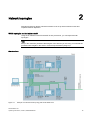
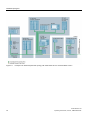
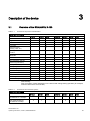
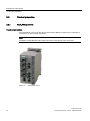
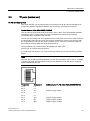
SCALANCE X-100
1
___________________
Introduction
2
___________________
Network topologies
SIMATIC NET
Industrial Ethernet switches
SCALANCE X-100
3
___________________
Description of the device
4
___________________
Assembly
5
___________________
Connecting up
Maintenance and
6
___________________
troubleshooting
Operating Instructions
7
___________________
Technical specifications
8
___________________
Certifications and approvals
9
___________________
Dimension drawings
07/2014
A2B00060666-05
Legal information
Warning notice system
This manual contains notices you have to observe in order to ensure your personal safety, as well as to prevent
damage to property. The notices referring to your personal safety are highlighted in the manual by a safety alert
symbol, notices referring only to property damage have no safety alert symbol. These notices shown below are
graded according to the degree of danger.
DANGER
indicates that death or severe personal injury will result if proper precautions are not taken.
WARNING
indicates that death or severe personal injury may result if proper precautions are not taken.
CAUTION
indicates that minor personal injury can result if proper precautions are not taken.
NOTICE
indicates that property damage can result if proper precautions are not taken.
If more than one degree of danger is present, the warning notice representing the highest degree of danger will
be used. A notice warning of injury to persons with a safety alert symbol may also include a warning relating to
property damage.
Qualified Personnel
The product/system described in this documentation may be operated only by personnel qualified for the specific
task in accordance with the relevant documentation, in particular its warning notices and safety instructions.
Qualified personnel are those who, based on their training and experience, are capable of identifying risks and
avoiding potential hazards when working with these products/systems.
Proper use of Siemens products
Note the following:
WARNING
Siemens products may only be used for the applications described in the catalog and in the relevant technical
documentation. If products and components from other manufacturers are used, these must be recommended
or approved by Siemens. Proper transport, storage, installation, assembly, commissioning, operation and
maintenance are required to ensure that the products operate safely and without any problems. The permissible
ambient conditions must be complied with. The information in the relevant documentation must be observed.
Trademarks
All names identified by ® are registered trademarks of Siemens AG. The remaining trademarks in this publication
may be trademarks whose use by third parties for their own purposes could violate the rights of the owner.
Disclaimer of Liability
We have reviewed the contents of this publication to ensure consistency with the hardware and software
described. Since variance cannot be precluded entirely, we cannot guarantee full consistency. However, the
information in this publication is reviewed regularly and any necessary corrections are included in subsequent
editions.
Siemens AG
Industry Sector
Postfach 48 48
90026 NÜRNBERG
GERMANY
A2B00060666-05
Ⓟ 07/2014 Subject to change
Copyright © Siemens AG 2008 - 2014.
All rights reserved
Table of contents
1
Introduction ............................................................................................................................................. 5
1.1
On the Operating Instructions ........................................................................................................ 5
1.2
On the product ............................................................................................................................... 7
2
Network topologies ............................................................................................................................... 11
3
Description of the device ....................................................................................................................... 13
4
5
6
3.1
Overview of the SCALANCE X-100 .............................................................................................13
3.2
3.2.1
3.2.2
3.2.3
3.2.4
3.2.5
3.2.6
3.2.7
Product properties ........................................................................................................................14
SCALANCE X104-2 .....................................................................................................................14
SCALANCE X106-1 .....................................................................................................................15
SCALANCE X108 ........................................................................................................................16
SCALANCE X108PoE .................................................................................................................17
SCALANCE X112-2 .....................................................................................................................18
SCALANCE X116 ........................................................................................................................19
SCALANCE X124 ........................................................................................................................20
3.3
TP ports (twisted pair) ..................................................................................................................21
3.4
FO port (fiber optic) ......................................................................................................................23
3.5
LEDs ............................................................................................................................................24
3.6
SET button ...................................................................................................................................25
Assembly .............................................................................................................................................. 27
4.1
Types of installation .....................................................................................................................27
4.2
Installation on a DIN rail ...............................................................................................................28
4.3
Installation on a standard rail .......................................................................................................30
4.4
Wall mounting ..............................................................................................................................31
Connecting up....................................................................................................................................... 33
5.1
Power supply................................................................................................................................33
5.2
Signaling contact ..........................................................................................................................35
5.3
Grounding ....................................................................................................................................36
5.4
IE FC RJ-45 Plug 180 ..................................................................................................................36
Maintenance and troubleshooting .......................................................................................................... 39
6.1
Possible sources of problems and how to deal with them ...........................................................39
SCALANCE X-100
Operating Instructions, 07/2014, A2B00060666-05
3
Table of contents
7
Technical specifications ........................................................................................................................ 41
7.1
SCALANCE X104-2 .................................................................................................................... 41
7.2
SCALANCE X106-1 .................................................................................................................... 44
7.3
SCALANCE X108 ....................................................................................................................... 47
7.4
SCALANCE X108PoE................................................................................................................. 50
7.5
SCALANCE X112-2 .................................................................................................................... 53
7.6
SCALANCE X116 ....................................................................................................................... 56
7.7
SCALANCE X124 ....................................................................................................................... 59
8
Certifications and approvals .................................................................................................................. 63
9
Dimension drawings .............................................................................................................................. 67
Index .................................................................................................................................................... 73
SCALANCE X-100
4
Operating Instructions, 07/2014, A2B00060666-05
1
Introduction
1.1
On the Operating Instructions
Purpose of the Operating Instructions
These Operating Instructions support you when commissioning networks with the Industrial
Ethernet switches of the SCALANCE X-100 product line.
Validity of the Operating Instructions
These operating instructions are valid for the following devices:
Device
Order number
SCALANCE X104-2
6GK5 104-2BB00-2AA3
SCALANCE X106-1
6GK5 106-1BB00-2AA3
SCALANCE X108
6GK5 108-0BA00-2AA3
SCALANCE X108PoE
6GK5 108-0PA00-2AA3
SCALANCE X112-2
6GK5 112-2BB00-2AA3
SCALANCE X116
6GK5 116-0BA00-2AA3
SCALANCE X124
6GK5 124-0BA00-2AA3
Further documentation
The "SIMATIC NET Industrial Ethernet Twisted Pair and Fiber Optic Networks" manual
contains additional information on other SIMATIC NET products that you can operate along
with the IE switches of the SCALANCE XB-000 product line in an Industrial Ethernet
network.
You can order the manual "SIMATIC NET Industrial Twisted Pair and Fiber Optic Networks",
release 05/2001, using the following order numbers:
6GK1970-1BA10-0AA0 German
6GK1970-1BA10-0AA1 English
6GK1970-1BA10-0AA2 French
6GK1970-1BA10-0AA4 Italian
You will also find this network manual on the Internet pages of Service & Support under the
following entry ID: 1172207 (http://support.automation.siemens.com/WW/view/en/1172207).
You will find further information in the "System Manual Industrial Ethernet" in the Manual
Collection.
You will find further information on the SCALANCE system on the Internet at
www.siemens.com/scalance (www.siemens.com/scalance).
You can obtain the "PROFINET Installation Guide" from the PROFIBUS User Organization
(PNO).
SCALANCE X-100
Operating Instructions, 07/2014, A2B00060666-05
5
Introduction
1.1 On the Operating Instructions
Audience
These Operating Instructions are intended for persons who commission networks with the IE
switches of the SCALANCE X-100 product line.
SIMATIC NET glossary
Explanations of many of the specialist terms used in this documentation can be found in the
SIMATIC NET glossary.
You will find the SIMATIC NET glossary here:
● SIMATIC NET Manual Collection or product DVD
The DVD ships with certain SIMATIC NET products.
● On the Internet under the following entry ID:
50305045 (http://support.automation.siemens.com/WW/view/en/50305045)
Security information
Siemens provides products and solutions with industrial security functions that support the
secure operation of plants, solutions, machines, equipment and/or networks. They are
important components in a holistic industrial security concept. With this in mind, Siemens’
products and solutions undergo continuous development. Siemens recommends strongly
that you regularly check for product updates.
For the secure operation of Siemens products and solutions, it is necessary to take suitable
preventive action (e.g. cell protection concept) and integrate each component into a holistic,
state-of-the-art industrial security concept. Third-party products that may be in use should
also be considered. For more information about industrial security, visit
http://www.siemens.com/industrialsecurity.
To stay informed about product updates as they occur, sign up for a product-specific
newsletter. For more information, visit http://support.automation.siemens.com.
SCALANCE X-100
6
Operating Instructions, 07/2014, A2B00060666-05
Introduction
1.2 On the product
1.2
On the product
What is possible?
The devices of the SCALANCE X100 product line allow the cost-effective installation of
Industrial Ethernet bus and star structures with switching functionality.
With the following IE switches, there are also electrical/optical media transitions:
● SCALANCE X104-2
● SCALANCE X106-1
● SCALANCE X112-2
IE switches with the suffix PoE also allow the supply of power to end devices over Ethernet
cables with Power-over-Ethernet complying with 802.3af.
Note
If devices are supplied over long 24 V power supply lines or networks, measures are
necessary to prevent interference by strong electromagnetic pulses on the supply lines.
These can result, for example, due to lightning or switching of large inductive loads.
One of the tests used to attest the immunity of these devices to electromagnetic interference
is the "surge immunity test" according to EN 61000-4-5. This test requires overvoltage
protection for the power supply lines. A suitable device is, for example, the Dehn Blitzductor
BVT AVD 24 V type no. 918 422 or a comparable protective element.
Manufacturer:
DEHN+SÖHNE GmbH+Co.KG Hans Dehn Str.1 Postfach 1640 D-92306 Neumarkt,
Germany
WARNING
When used in hazardous environments corresponding to Class I, Division 2 or Class I,
Zone 2, the device must be installed in a cabinet or a suitable enclosure.
WARNING
To comply with EU Directive 94/9 (ATEX95), this enclosure must meet the requirements of
at least IP54 in compliance with EN 60529.
WARNING
EXPLOSION HAZARD
DO NOT CONNECT OR DISCONNECT EQUIPMENT WHEN A FLAMMABLE OR
COMBUSTIBLE ATMOSPHERE IS PRESENT.
SCALANCE X-100
Operating Instructions, 07/2014, A2B00060666-05
7
Introduction
1.2 On the product
Components of the product
The following components are supplied with a SCALANCE X-100:
● IE Switch SCALANCE X-100
● 2-pin plug-in terminal block (signaling contact)
● 4-pin plug-in terminal block (power supply)
● Product information
Accessories
Component
Packaging unit
Order number
IE FC Stripping Tool
1
6GK1901-1GA00
IE FC blade cassettes (5 mm)
1
6GK1901-1GB01
IE FC TP standard cable GP
1
6XV1840-2AH10
IE FC TP trailing cable
1
6XV1840-3AH10
IE FC TP marine cable
1
6XV1840-4AH10
IE FC TP trailing cable GP
1
6XV1870-2D
IE FC TP flexible cable GP
1
6XV1870-2B
IE FC TP FRNC cable GP
1
6XV1871-2F
IE FC TP festoon cable GP
1
6XV1871-2S
IE FC TP food cable
1
6XV1871-2L
IE TP torsion cable
1
6XV1870-2F
FO standard cable GP (50/125)
1
6XV1873-2A
FO trailing cable (50/125)
1
6XV1873-2C
FO trailing cable GP (50/125)
1
6XV1873-2D
FO ground cable (50/125)
1
6XV1873-2G
FO FRNC cable (50/125)
1
6XV1873-2B
IE FC RJ-45 Plug 180
1
6GK1901-1BB10-2AA0
IE FC RJ-45 Plug 180
10
6GK1901-1BB10-2AB0
IE FC RJ-45 Plug 180
50
6GK1901-1BB10-2AE0
SCALANCE X-100
8
Operating Instructions, 07/2014, A2B00060666-05
Introduction
1.2 On the product
Unpacking and checking
WARNING
Do not use any parts that show evidence of damage
If you use damaged parts, there is no guarantee that the device will function according to
the specification.
If you use damaged parts, this can lead to the following problems:
• Injury to persons
• Loss of the approvals
• Violation of the EMC regulations
• Damage to the device and other components
Use only undamaged parts.
1. Make sure that the package is complete.
2. Check all the parts for transport damage.
SCALANCE X-100
Operating Instructions, 07/2014, A2B00060666-05
9
Introduction
1.2 On the product
SCALANCE X-100
10
Operating Instructions, 07/2014, A2B00060666-05
Network topologies
2
Switching technology allows extensive networks to be set up with numerous nodes and
simplifies network expansion.
Which topologies can be implemented?
Using the IE switches of the SCALANCE X-100 product line, you can implement star
topologies.
Note
Keep to the maximum permitted cable lengths of the devices you are using. You will find the
permitted cable lengths in the section "Technical specifications (Page 41)".
Star topology
Figure 2-1
Example of an electrical star topology with SCALANCE X124
SCALANCE X-100
Operating Instructions, 07/2014, A2B00060666-05
11
Network topologies
Figure 2-2
Example of an electrical/optical star topology with SCALANCE X112-2 and SCALANCE X104-2
SCALANCE X-100
12
Operating Instructions, 07/2014, A2B00060666-05
3
Description of the device
3.1
Table 3- 1
Overview of the SCALANCE X-100
Overview of the product characteristics
Device type SCALANCE
X104-2
X106-1
X108
X108PoE
X112-2
X116
X124
SIMATIC environment
+
+
+
+
+
+
+
Diagnostics LED
+
+
+
+
+
+
+
24 VDC
+
+
+
+
+
+
+
2 x 24 VDC
+
+
+
+
+
+
+
Compact housing
(securing collar, etc.)
+
+
+
+
+
+
+
Signaling contact + on-site
operation
+
+
+
+
+
+
+
Diagnostics: Web, SNMP,
PROFINET
-
-
-
-
-
-
-
C-PLUG
-
-
-
-
-
-
-
Ring redundancy with RM
-
-
-
-
-
-
-
Passive ring redundancy
-
-
-
-
-
-
-
Standby redundancy
-
-
-
-
-
-
-
IRT capability
-
-
-
-
-
-
-
Fast learning
-
-
-
-
-
-
-
Passive listening
-
-
-
-
-
-
-
Log table
-
-
-
-
-
-
-
SNTP + SICLOCK
-
-
-
-
-
-
-
Cut Through
-
-
-
-
-
-
-
Number of PoE ports
-
-
-
2
-
-
-
Fast learning:
Fast recognition of MAC addresses on the device that change during operation (for example,
when an end node is reconnected).
Table 3- 2
Overview of the connection options
Device type SCALANCE
X104-2
X106-1
X108
X108PoE
X112-2
X116
X124
TP (RJ-45)
Fast Ethernet 10 / 100 Mbps
4
6
8
8
12
16
24
Fiber multimode (BFOC)
Fast Ethernet 100 Mbps
2
1
-
-
2
-
-
SCALANCE X-100
Operating Instructions, 07/2014, A2B00060666-05
13
Description of the device
3.2 Product properties
3.2
Product properties
3.2.1
SCALANCE X104-2
Possible connections
The SCALANCE X104-2 has four RJ-45 jacks and two BFOC sockets for the connection of
end devices or other network segments.
Note
The BFOC socket (Bayonet Fiber Optic Connector) corresponds to the ST socket.
Figure 3-1
SCALANCE X104-2
SCALANCE X-100
14
Operating Instructions, 07/2014, A2B00060666-05
Description of the device
3.2 Product properties
3.2.2
SCALANCE X106-1
Possible connections
The SCALANCE X106-1 has six RJ-45 jacks and a BFOC socket for the connection of end
devices or other network segments.
Note
The BFOC socket (Bayonet Fiber Optic Connector) corresponds to the ST socket.
Figure 3-2
SCALANCE X106-1
SCALANCE X-100
Operating Instructions, 07/2014, A2B00060666-05
15
Description of the device
3.2 Product properties
3.2.3
SCALANCE X108
Possible connections
The SCALANCE X108 has eight RJ-45 jacks for the connection of end devices or other
network segments.
Figure 3-3
SCALANCE X108
SCALANCE X-100
16
Operating Instructions, 07/2014, A2B00060666-05
Description of the device
3.2 Product properties
3.2.4
SCALANCE X108PoE
Possible connections
The SCALANCE X108 PoE has eight RJ-45 jacks for the connection of end devices or other
network segments. Ports 1 to 2 do not have the PoE function.
Figure 3-4
SCALANCE X108PoE
Power over Ethernet (PoE) function
The PoE function allows the power supply of connected Ethernet devices via the Ethernet
cable so that the end device does not need a separate power supply.
Per PoE port of the PSE (Power Sourcing Equipment), a maximum of 15.4 W power are
available according to the 802.3af standard.
Note
With a 100 m long cable connected, the end device then has a maximum of 12.95 W
available.
You will find more information on the PoE function in the section "TP ports (Page 21)".
SCALANCE X-100
Operating Instructions, 07/2014, A2B00060666-05
17
Description of the device
3.2 Product properties
3.2.5
SCALANCE X112-2
Possible connections
The SCALANCE X112-2 has twelve RJ-45 jacks and two BFOC sockets for the connection
of end devices or other network segments.
Note
The BFOC socket (Bayonet Fiber Optic Connector) corresponds to the ST socket.
Figure 3-5
SCALANCE X112-2
SCALANCE X-100
18
Operating Instructions, 07/2014, A2B00060666-05
Description of the device
3.2 Product properties
3.2.6
SCALANCE X116
Possible connections
The SCALANCE X116 has 16 RJ-45 jacks for the connection of end devices or other
network segments.
Figure 3-6
SCALANCE X116
SCALANCE X-100
Operating Instructions, 07/2014, A2B00060666-05
19
Description of the device
3.2 Product properties
3.2.7
SCALANCE X124
Possible connections
The SCALANCE X124 has 24 RJ-45 jacks for the connection of end devices or other
network segments.
Figure 3-7
SCALANCE X124
SCALANCE X-100
20
Operating Instructions, 07/2014, A2B00060666-05
Description of the device
3.3 TP ports (twisted pair)
3.3
TP ports (twisted pair)
RJ-45 connector pinout
With SCALANCE X-100, the twisted-pair port is designed as an RJ-45 jack with MDI-X pin
assignment (Medium Dependent Interface Autocrossover) of a network component.
Special features of the SCALANCE X108PoE
Over and above the pure Ethernet functionality, ports 1 and 2 of the SCALANCE X108PoE
can also be used to supply power to Power-over-Ethernet end devices (for example
SCALANCE-W) in compliance with 802.3af.
The two ports providing PoE are supplied from the same power source. This means that they
are electrically interconnected. They are however isolated from ground, from the ports that
do not provide PoE and from the power connector (24 V). Their use is therefore subject to
the conditions listed in IEEE 802.3af for Environment A.
The ports that do not provide PoE are all isolated from each other.
Ports 3 to 8 do not have the PoE function.
To supply PoE end devices, 4 or 8-wire connecting cables can be used (according to IEEE
802.3).
Note
Ethernet devices without PoE functionality can also be connected to ports 1 and 2. A voltage
is applied only after the SCALANCE X108 PoE has detected a PoE end device complying
with the standard at the port.
Pin number
Assignment
Additional pins P1, P2 of the SCALANCE X108PoE
Pin 8
n. c.
-
Pin 7
n. c.
-
Pin 6
TD-
positive supply voltage
Pin 5
n. c.
-
Pin 4
n. c.
-
Pin 3
TD+
positive supply voltage
Pin 2
RD-
negative supply voltage
Pin 1
RD+
negative supply voltage
SCALANCE X-100
Operating Instructions, 07/2014, A2B00060666-05
21
Description of the device
3.3 TP ports (twisted pair)
Note
Permitted cable lengths
TP cords or TP-XP cords with a maximum length of 10 m can be connected to the TP port
with the RJ-45 jack.
With the IE FC cables and IE FC RJ-45 plugs 180, an overall cable length of a maximum of
100 m is permitted between two devices depending on the cable type.
Autonegotiation
With the autonegotiation mechanism, repeaters and end devices can automatically
determine the transmission speed and the transmission mode of the partner port. This
makes it possible to configure different devices automatically.
Two components connected to a link segment can exchange information about the data
transfer and can adapt their settings to each other. The mode with the highest possible
speed is set.
Note
Devices not supporting autonegotiation must be set permanently to 100 Mbps half duplex or
10 Mbps half duplex.
Note
The IE switches of the SCALANCE X-100 product line are plug-and-play devices that require
no settings during commissioning.
Auto polarity exchange
If the pair of receiving cables is connected incorrectly (RD+ and RD- interchanged), the
polarity is adapted automatically.
MDI / MDI-X autocrossover function
With the MPI/MDI-X autocrossover function, the send and receive contacts of an Ethernet
port are assigned automatically. The assignment depends on the cable with which the
communications partner is connected. This means that it does not matter whether the port is
connected using a patch cable or crossover cable. This prevents malfunctions resulting from
mismatching send and receive wires. This makes installation much easier for the user.
The IE Switches SCALANCE X-100 all support the MDI / MDI-X autocrossover function.
NOTICE
Formation of loops
Note that the direct connection of two ports or accidental connection over several switches
causes an illegal loop that can cause network overload and failure.
SCALANCE X-100
22
Operating Instructions, 07/2014, A2B00060666-05
Description of the device
3.4 FO port (fiber optic)
3.4
FO port (fiber optic)
Transmission speed
The transmission speed of the optical Fast Ethernet ports is 100 Mbps.
Transmission technique
The transmission mode for 100Base-FX is specified in the IEEE 802.3 standard.
Since the full duplex mode and the transmission rate cannot be modified for optical
transmission, autonegotiation cannot be selected.
Transmission medium
Data transmission is over multimode fiber-optic cable (FO cable). The wavelength is 1310
nm.
Multimode fiber-optic cables are used with a core of 50 or 62.5 µm; the light source is an
LED.
The outer diameter of the FO cable is 125 µm.
Transmission range
The maximum transmission range (segment length) is as follows:
● with 62.5/125 µm fiber multimode SIMATIC NET cable: 4 km
● with 50.0/125 µm fiber multimode SIMATIC NET cable: 5 km
Connectors
The cables are connected over BFOC sockets.
SCALANCE X-100
Operating Instructions, 07/2014, A2B00060666-05
23
Description of the device
3.5 LEDs
3.5
LEDs
Fault LED "F" (red LED)
The fault LED indicates the incorrect functioning of the device.
LED color
LED status
Meaning
Red
Lit
The SCALANCE switch X-100 detects a fault. At the same time, the signaling contact
opens.
The following faults/errors are detected:
1. Link down event on a monitored port.
2. Loss of the power supply of one of the two redundant power supplies or the
power supply drops below 14 V.
3. Both power supplies are below approximately 14 V (voltage too low).
-
Off
No problem has been detected by the SCALANCE X-100.
Power LED "L" (green LED)
The power LED shows the status of the power supply.
LED color
LED status
Meaning
Green
Lit
Power supply L1 or L2 is connected.
-
Off
Power supply L1 and L2 are not connected or L1 and L2 <14 V.
Note
If the green LED is not lit, no other signal LED lights up either.
Port LEDs "P" (green/yellow LEDs)
The port LEDs indicate the status of the ports.
LED color
LED status
Meaning
Green
Lit
Link exists, no data reception at port
Yellow
Lit
Link exists, data reception at port
Yellow
Flashing
Setting or display of the fault mask
SCALANCE X-100
24
Operating Instructions, 07/2014, A2B00060666-05
Description of the device
3.6 SET button
3.6
SET button
Function
With the SET button, you can display and change the set fault mask.
Setting the fault mask
Factory setting
When supplied (factory defaults), the fault mask is set so that the power supply L1+/M1 is
monitored. No ports are monitored.
If you connect a power supply to L2+/M2, adapt the fault mask accordingly: Clear the error
LED and the signaling contact or set the fault mask to the power supply L2+/M2.
Changing the setting
The changed settings remain after cycling power to the device.
Different settings are made depending on how long you hold down the SET button, as
described in the following table:
Phase
Description
1
LEDs flash at 5 Hz
The currently set fault mask is displayed. The LEDs of the monitored
ports flash.
If no fault mask is set, all port LEDs flash one after the other.
If you release the button in phase 1, this has no effect.
2
LEDs flash at 2.5 Hz
The current status is displayed.
•
The LEDs of the ports at which there is currently a link flash.
•
The LEDs of the connected power supply flash.
If you release the button in phase 2, this has no effect.
3
This new status is adopted and stored as the new fault mask in phase 3.
LEDs flashing
If you release the SET button while the LEDs are still flashing, storing is
aborted.
LEDs lit
If you release the SET button as soon as the LEDs light up, the current
settings will be stored.
The stored status is displayed.
•
The monitored ports are indicated by statically lit LEDs.
•
The monitored power supply is indicated by statically lit LEDs.
SCALANCE X-100
Operating Instructions, 07/2014, A2B00060666-05
25
Description of the device
3.6 SET button
Note
If an empty fault mask is set or needs to be set, the 2 port LEDs flash alternately. If the fault
mask is empty, no port is monitored.
Note
The PoE voltage at the PoE ports cannot be monitored using the fault mask.
Error/fault
If the link is lost at a monitored port or a monitored power supply is lost, this is signaled as
follows:
● the red fault LED lights up
● the signaling contact is opened
SCALANCE X-100
26
Operating Instructions, 07/2014, A2B00060666-05
4
Assembly
4.1
Types of installation
The devices can be installed in the following ways:
● Installation on a 35 mm DIN rail
● Installation on a SIMATIC S7-300 standard rail
● Wall mounting
WARNING
Ambient temperature between 55 °C and 60 °C
If a device is operated in an ambient temperature of more than 55 °C, the temperature of
the device housing may be higher than 70 °C. The device must therefore be installed so
that it is only accessible to service personnel or users that are aware of the reason for
restricted access and the required safety measures at an ambient temperature higher than
55 °C.
WARNING
If a SCALANCE X108PoE is operated at ambient temperatures between 55 °C and 60 °C,
there must be a minimum clearance of 40 mm to neighboring modules.
WARNING
If the cable or conduit entry point exceeds 70 °C or the branching point of conductors
exceeds 80 °C, special precautions must be taken. If the equipment is operated in an air
ambient in excess of 50 °C to 60 °C, only use cables with admitted maximum operating
temperature of at least 80 ℃.
WARNING
Protective measures need to be taken to ensure that the rated voltage of the equipment
cannot be exceeded by more than 40% by transient surges. This is achieved by operating
the equipment only with SELV circuits (previously also PELV). Under no circumstances
must transient surges exceed 119 V.
Note
When installing and operating the device, keep to the installation instructions and safetyrelated notices as described here and in the manual "SIMATIC NET Industrial Ethernet
Twisted Pair and Fiber Optic Networks".
Note
Provide suitable shade to protect the device against direct sunlight. This avoids unwanted
warming of the device and prevents premature aging of the device and cabling.
SCALANCE X-100
Operating Instructions, 07/2014, A2B00060666-05
27
Assembly
4.2 Installation on a DIN rail
4.2
Installation on a DIN rail
Installation
To install the device on a 35 mm DIN rail complying with DIN EN 50022, follow the steps
below:
1. Place the second housing guide of the device on the top edge of the DIN rail.
2. Press the device down against the DIN rail until the spring catch locks in place.
3. Fit the connectors for the power supply. See also section "Power supply (Page 33)".
4. Fit the connectors for the signaling contacts. See also section "Signaling contacts
(Page 35)".
5. Insert the terminal blocks into the sockets on the device.
WARNING
Use of the SCALANCE X108PoE in shipbuilding
When used in shipbuilding, mounting the SCALANCE X108PoE on 35 mm DIN rails is
not permitted.
35 mm DIN rails do not ensure sufficient stability when used in shipbuilding.
Figure 4-1
Installation on a 35 mm DIN rail
SCALANCE X-100
28
Operating Instructions, 07/2014, A2B00060666-05
Assembly
4.2 Installation on a DIN rail
Uninstalling
To remove the device from the DIN rail, follow the steps below:
1. Disconnect all connected cables.
2. Release the DIN rail catch on the bottom of the device using a screwdriver.
3. Pull the lower part of the device away from the DIN rail.
Figure 4-2
Removal from a 35 mm DIN rail
SCALANCE X-100
Operating Instructions, 07/2014, A2B00060666-05
29
Assembly
4.3 Installation on a standard rail
4.3
Installation on a standard rail
Installation on a SIMATIC S7-300 standard rail
To install the device on an S7-300 standard rail, follow the steps below:
1. Place the first housing guide of the device on the top edge of the S7-300 standard rail.
2. Screw the device to the underside of the standard rail (tightening torque 2 Nm).
3. Fit the connectors for the power supply. See also section "Power supply (Page 33)".
4. Fit the connectors for the signaling contacts. See also section "Signaling contacts
(Page 35)".
5. Insert the terminal blocks into the sockets on the device.
Figure 4-3
Installation on a SIMATIC S7-300 standard rail
Uninstalling
To remove the device from the S7-300 standard rail, follow the steps below:
1. Disconnect all connected cables.
2. Release the screw holding the device on the bottom of the standard rail.
3. Lift the device off the standard rail.
SCALANCE X-100
30
Operating Instructions, 07/2014, A2B00060666-05
Assembly
4.4 Wall mounting
4.4
Wall mounting
To mount the device on a wall, you require the following:
● 4 wall plugs, 6 mm in diameter and 30 mm long
● 4 screws 3.5 mm in diameter and 40 mm long
To mount the device on a wall, follow the steps below:
1. Prepare the drill holes for wall mounting. For the precise dimensions, refer to the section
"Dimension drawings (Page 67)".
2. Fit the connectors for the power supply. See also section "Power supply (Page 33)".
3. Fit the connectors for the signaling contacts. See also section "Signaling contacts
(Page 35)".
4. Insert the terminal blocks into the sockets on the device.
5. Screw the device to the wall.
Note
The wall mounting must be capable of supporting at least four times the weight of the device.
SCALANCE X-100
Operating Instructions, 07/2014, A2B00060666-05
31
Assembly
4.4 Wall mounting
SCALANCE X-100
32
Operating Instructions, 07/2014, A2B00060666-05
5
Connecting up
5.1
Power supply
The power supply is connected using a 4-pin plug-in terminal block. The power supply can
be connected redundantly. Both inputs are isolated. There is no distribution of load. When a
redundant power supply is used, the power supply unit with the higher output voltage
supplies the device alone. The power supply is connected over a high resistance with the
enclosure to allow an ungrounded set up. The two power supplies are non-floating.
The following figure shows the position of the power supply of the SCALANCE X-100 IE
switches and the assignment of the terminal block.
Pin number
Pin 1
Assignment
L1+ (24 VDC)
Pin 2
M1 (ground)
Pin 3
M2 (ground)
Pin 4
L2+ (24 VDC)
WARNING
Incorrect power supply
The power supply unit to supply the device must comply with NEC Class 2 (voltage range
18 - 32 V, current requirement 350 mA).
Do not operate the device with an AC voltage.
Never operate the device with DC voltages higher than 32 VDC.
SCALANCE X-100
Operating Instructions, 07/2014, A2B00060666-05
33
Connecting up
5.1 Power supply
WARNING
The equipment is designed for operation with Safety Extra-Low Voltage (SELV) by a
Limited Power Source (LPS).
This means that only SELV / LPS complying with IEC 60950-1 / EN 60950-1 / VDE 0805-1
must be connected to the power supply terminals. The power supply unit for the equipment
power supply must comply with NEC Class 2, as described by the National Electrical Code
(r) (ANSI / NFPA 70).
If the equipment is connected to a redundant power supply (two separate power supplies),
both must meet these requirements.
SCALANCE X-100
34
Operating Instructions, 07/2014, A2B00060666-05
Connecting up
5.2 Signaling contact
5.2
Signaling contact
The signaling contact is connected to a 2-pin plug-in terminal block. The signaling contact
(relay contact) is a floating switch with which error/fault states can be signaled by breaking
the contact.
NOTICE
Damage due to voltage being too high
The signaling contact can be subjected to a maximum load of 100 mA (safety extra-low
voltage SELV, 24 VDC).
Higher voltages or currents can damage the device!
The following figure shows the position of the signaling contacts of the SCALANCE X-100 IE
switches and the assignment of the terminal block.
Pin number
Pin 1
Assignment
F1
Pin 2
F2
The following errors/faults can be signaled by the signaling contact:
● The failure of a link at a monitored port.
● The failure of one of the two monitored power supplies.
The connection or disconnection of a communication node on an unmonitored port does not
lead to an error message.
The signaling contact remains activated until the error/fault is eliminated or until the current
status is applied as the new desired status using the button.
When the device is turned off, the signaling contact is always activated (open).
SCALANCE X-100
Operating Instructions, 07/2014, A2B00060666-05
35
Connecting up
5.3 Grounding
5.3
Grounding
Installation on a DIN rail
The device is grounded over the DIN rail.
S7 standard rail
The device is grounded over its rear panel and the neck of the screw.
Wall mounting
The device is grounded by the securing screw in the unpainted hole.
Note that the device must be grounded over a securing screw with as low a low resistance
as possible.
If the device is mounted on a non-conductive base, a grounding cable must be fitted. The
grounding cable is not supplied with the device. Connect the paint-free surface of the device
to the nearest grounding point using the grounding cable.
5.4
IE FC RJ-45 Plug 180
The rugged node connectors are designed for industry with PROFINET-compliant
connectors and provide additional strain and bending relief with a locking mechanism on the
casing.
Fitting the IE FC RJ45 Plug 180 to the IE FC Standard Cable
You will find the notes on installation in the instructions that ship with the IE FC RJ45 Plug
180.
Figure 5-1
IE FC 45 Plug 180
SCALANCE X-100
36
Operating Instructions, 07/2014, A2B00060666-05
Connecting up
5.4 IE FC RJ-45 Plug 180
Plugging in the IE FC RJ45 Plug 180
Plug the IE FC RJ45 Plug 180 into the twisted-pair port of the device until it locks in place.
Figure 5-2
Plugging in the IE FC RJ45 Plug 180
With its tight fit and locking mechanism with the PROFINET-compliant male connector
IE FC RJ45 Plug 180, the securing collar on the TP port of the device ensures a rugged
node attachment that provides strain and bending relief for the RJ-45 jack.
Pulling the IE FC RJ45 Plug 180
Press on the locking lever of the IE FC RJ45 Plug 180 gently to remove the plug.
If there is not enough space to release the lock with your hand, you can also use a 2.5 mm
screwdriver. You can then remove the IE FC RJ45 Plug 180 from the RJ-45 jack.
SCALANCE X-100
Operating Instructions, 07/2014, A2B00060666-05
37
Connecting up
5.4 IE FC RJ-45 Plug 180
SCALANCE X-100
38
Operating Instructions, 07/2014, A2B00060666-05
Maintenance and troubleshooting
6.1
6
Possible sources of problems and how to deal with them
Fuses
Some of the Industrial Ethernet switches of the SCALANCE X-100 product line have a
resettable fuse / PTC. If the fuse triggers (all LEDs are off despite correctly applied power
supply), the device should be disconnected from the power supply for approximately 30
minutes before turning it on again.
Link display on the optical ports
The Industrial Ethernet switches SCALANCE X104-2, SCALANCE X106-1 and
SCALANCE X112-2 support "far-end fault" on the optical ports but do not use this for the
corresponding link display. This means that if there is only a cable connected in the receive
direction on the optical port, a far-end fault is detected and no data is forwarded. The Link
LED is already lit.
LED display when voltage drops
If both of the power supplies drop below approximately 14 V, this reduced voltage is
indicated by the red fault LED. The L LEDs go off.
Device defective
If a fault develops, please send the device to your SIEMENS service center for repair.
Repairs on-site are not possible.
SCALANCE X-100
Operating Instructions, 07/2014, A2B00060666-05
39
Maintenance and troubleshooting
6.1 Possible sources of problems and how to deal with them
SCALANCE X-100
40
Operating Instructions, 07/2014, A2B00060666-05
Technical specifications
7.1
Table 7- 1
7
SCALANCE X104-2
Technical specifications of the SCALANCE X104-2
Technical specifications
Order number
SCALANCE X104-2
6GK5104-2BB00-2AA3
Connection to Industrial Ethernet
Number
4
Design
RJ-45 jacks with MDI-X pinning
Properties
Half / full duplex
Transmission speed
10/100 Mbps
Optical connectors
Number
2
Design
BFOC sockets
Properties
Full duplex to 100 Base-FX
Transmission speed
100 Mbps
Permitted cable lengths (Industrial
Ethernet)
Alternative combinations per length
range
0 to 55 m
•
Max. 55 m IE TP Torsion Cable
with IE FC RJ45 Plug 180
•
Max. 45 m IE TP Torsion Cable
with IE FC RJ45 + 10 m TP Cord
via IE FC RJ45 Outlet
•
Max. 85 m IE FC TP
Marine/Trailing Cable with
IE FC RJ45 Plug 180
•
Max. 75 m IE FC TP
Marine/Trailing Cable + 10 m
TP Cord via IE FC RJ45 Outlet
•
Max. 100 m IE FC TP Standard
Cable with IE FC RJ45 Plug 180
•
Max. 90 m IE FC TP Standard
Cable + 10 m TP Cord via
IE FC RJ45 Outlet
0 ... 85 m
0 ... 100 m
SCALANCE X-100
Operating Instructions, 07/2014, A2B00060666-05
41
Technical specifications
7.1 SCALANCE X104-2
Technical specifications
Optical parameters
Cable type
Multimode glass FO cable, cable cross sections 62.5/125 μm and 50/125 μm
Permitted cable length (glass FO
cable)
Cable cross-section
Attenuation
Permitted cable length
•
62.5/125 μm
•
0 to 4000 m
•
50/125 μm
•
0 to 5000 m
≤ 1 dB/km at 1300 nm
1200 MHz x km at 1300 nm
6 dB max. permitted FO cable
attenuation with
3 dB link power margin
Electrical data
Power supply
Voltage range
18 to 32 VDC Safe Extra Low Voltage
(SELV)
Rated voltage
24 VDC
Design
4-terminal plug-in block
Current
max. 100 mA
Rated voltage
24 VDC
Design
2-pin plug-in terminal block
Current consumption
Typical
160 mA
Power loss at 24 VDC
Typical
3.8 W
Signaling contact
Overvoltage protection at input
PTC resettable fuse (0.6 A / 60 V)
Permitted ambient conditions
Ambient temperature
During operation
-10 °C to +60 °C
During storage
-40 °C to +80 °C
During transportation
-40 °C to +80 °C
Relative humidity
During operation
≤ 95 % no condensation
Operating altitude
During operation
≤ 2,000 m above sea level at max. 56 °C
ambient temperature
≤ 3,000 m above sea level at max. 50 °C
ambient temperature
Design, dimensions and weight
Immunity to interference
EN 61000-6-2
Emission
EN 61000-6-4
Degree of protection
IP 30
MTBF (EN/IEC 61709, 40 °C)
134.87 years
Housing material
Basic housing
Die cast aluminum, powder coated
Front cover
Polyphenylene ether + polystyrene
(PPE+PS plastic)
Weight
780 g
Dimensions (W x H x D)
60 x 125 x 124 mm
SCALANCE X-100
42
Operating Instructions, 07/2014, A2B00060666-05
Technical specifications
7.1 SCALANCE X104-2
Technical specifications
Installation options
•
Installation on a DIN rail
•
Installation on an S7-300 standard rail
•
Wall mounting
Switching properties
Aging time
30 seconds
Max. number of learnable MAC
addresses
2048
Response to LLDP frames
Blocking
Response to spanning tree BPDU
frames
Forwarding
QoS priority queues
4
Note
The number of SCALANCE X Industrial Ethernet switches connected in a line influences the
frame delay time.
When a frame passes through devices of the SCALANCE X-100 product line, it is delayed by
the store and forward function of the switch
• with a 64 byte frame length by approx. 10 microseconds (at 100 Mbps)
• with a 1500 byte frame length by approx. 130 microseconds (at 100 Mbps)
This means that the more devices of the SCALANCE X-100 product line, the frame passes
through, the longer the frame delay.
Note
Temperature code for c-UL-us for hazardous locations, FM and ATEX Zone 2
You will find the temperature code "T.." or the maximum ambient temperature "Ta: .." on the
type plate.
SCALANCE X-100
Operating Instructions, 07/2014, A2B00060666-05
43
Technical specifications
7.2 SCALANCE X106-1
7.2
Table 7- 2
SCALANCE X106-1
Technical specifications of the SCALANCE X106-1
Technical specifications
Order number
SCALANCE X106-1
6GK5106-1BB00-2AA3
Connection to Industrial Ethernet
Number
6
Design
RJ-45 jacks with MDI-X pinning
Properties
Half / full duplex
Transmission speed
10/100 Mbps
Optical connectors
Number
1
Design
BFOC socket
Properties
Full duplex to 100 Base-FX
Transmission speed
100 Mbps
Permitted cable lengths (Industrial
Ethernet)
Alternative combinations per length
range
0 to 55 m
•
Max. 55 m IE TP Torsion Cable
with IE FC RJ45 Plug 180
•
Max. 45 m IE TP Torsion Cable
with IE FC RJ45 + 10 m TP Cord
via IE FC RJ45 Outlet
•
Max. 85 m IE FC TP
Marine/Trailing Cable with
IE FC RJ45 Plug 180
•
Max. 75 m IE FC TP
Marine/Trailing Cable + 10 m
TP Cord via IE FC RJ45 Outlet
•
Max. 100 m IE FC TP Standard
Cable with IE FC RJ45 Plug 180
•
Max. 90 m IE FC TP Standard
Cable + 10 m TP Cord via
IE FC RJ45 Outlet
0 ... 85 m
0 ... 100 m
SCALANCE X-100
44
Operating Instructions, 07/2014, A2B00060666-05
Technical specifications
7.2 SCALANCE X106-1
Technical specifications
Optical parameters
Cable type
Multimode glass FO cable, cable cross sections 62.5/125 μm and 50/125 μm
Permitted cable length (glass FO
cable)
Cable cross-section
Attenuation
Permitted cable length
•
62.5/125 μm
•
0 to 4000 m
•
50/125 μm
•
0 to 5000 m
≤ 1 dB/km at 1300 nm
1200 MHz x km at 1300 nm
6 dB max. permitted FO cable
attenuation with
3 dB link power margin
Electrical data
Power supply
Voltage range
18 to 32 VDC Safe Extra Low Voltage
(SELV)
Rated voltage
24 VDC
Design
4-terminal plug-in block
Current
max. 100 mA
Rated voltage
24 VDC
Design
2-pin plug-in terminal block
Current consumption
Typical
150 mA
Power loss at 24 VDC
Typical
3.6 W
Signaling contact
Overvoltage protection at input
PTC resettable fuse (0.6 A / 60 V)
Permitted ambient conditions
Ambient temperature
During operation
-10 °C to +60 °C
During storage
-40 °C to +80 °C
During transportation
-40 °C to +80 °C
Relative humidity
During operation
≤ 95 % no condensation
Operating altitude
During operation
≤ 2,000 m above sea level at max. 56 °C
ambient temperature
≤ 3,000 m above sea level at max. 50 °C
ambient temperature
Design, dimensions and weight
Immunity to interference
EN 61000-6-2
Emission
EN 61000-6-4
Degree of protection
IP 30
MTBF (EN/IEC 61709, 40 °C)
136.65 years
Housing material
Basic housing
Die cast aluminum, powder coated
Front cover
Polyphenylene ether + polystyrene
(PPE+PS plastic)
Weight
780 g
Dimensions (W x H x D)
60 x 125 x 124 mm
SCALANCE X-100
Operating Instructions, 07/2014, A2B00060666-05
45
Technical specifications
7.2 SCALANCE X106-1
Technical specifications
Installation options
•
Installation on a DIN rail
•
Installation on an S7-300 standard rail
•
Wall mounting
Switching properties
Aging time
30 seconds
Max. number of learnable MAC
addresses
2048
Response to LLDP frames
Blocking
Response to spanning tree BPDU
frames
Forwarding
QoS priority queues
4
Note
The number of SCALANCE X Industrial Ethernet switches connected in a line influences the
frame delay time.
When a frame passes through devices of the SCALANCE X-100 product line, it is delayed by
the store and forward function of the switch
• with a 64 byte frame length by approx. 10 microseconds (at 100 Mbps)
• with a 1500 byte frame length by approx. 130 microseconds (at 100 Mbps)
This means that the more devices of the SCALANCE X-100 product line, the frame passes
through, the longer the frame delay.
Note
Temperature code for c-UL-us for hazardous locations, FM and ATEX Zone 2
You will find the temperature code "T.." or the maximum ambient temperature "Ta: .." on the
type plate.
SCALANCE X-100
46
Operating Instructions, 07/2014, A2B00060666-05
Technical specifications
7.3 SCALANCE X108
7.3
Table 7- 3
SCALANCE X108
Technical specifications of the SCALANCE X108
Technical specifications
Order number
SCALANCE X108
6GK5108-0BA00-2AA3
Connection to Industrial Ethernet
Number
8
Design
RJ-45 jacks with MDI-X pinning
Properties
Half / full duplex
Transmission speed
10/100 Mbps
Permitted cable lengths (Industrial
Ethernet)
Alternative combinations per length
range
0 to 55 m
•
Max. 55 m IE TP Torsion Cable
with IE FC RJ45 Plug 180
•
Max. 45 m IE TP Torsion Cable
with IE FC RJ45 + 10 m TP Cord
via IE FC RJ45 Outlet
•
Max. 85 m IE FC TP
Marine/Trailing Cable with
IE FC RJ45 Plug 180
•
Max. 75 m IE FC TP
Marine/Trailing Cable + 10 m
TP Cord via IE FC RJ45 Outlet
•
Max. 100 m IE FC TP Standard
Cable with IE FC RJ45 Plug 180
•
Max. 90 m IE FC TP Standard
Cable + 10 m TP Cord via
IE FC RJ45 Outlet
0 ... 85 m
0 ... 100 m
Electrical data
Power supply
Voltage range
18 to 32 VDC Safe Extra Low Voltage
(SELV)
Rated voltage
24 VDC
Design
4-terminal plug-in block
Current
max. 100 mA
Rated voltage
24 VDC
Design
2-pin plug-in terminal block
Current consumption
Typical
140 mA
Power loss at 24 VDC
Typical
3.36 W
Signaling contact
Overvoltage protection at input
PTC resettable fuse (0.6 A / 60 V)
SCALANCE X-100
Operating Instructions, 07/2014, A2B00060666-05
47
Technical specifications
7.3 SCALANCE X108
Technical specifications
Permitted ambient conditions
Ambient temperature
During operation
-20 °C to +70 °C
During storage
-40 °C to +80 °C
During transportation
-40 °C to +80 °C
Relative humidity
During operation
≤ 95 % no condensation
Operating altitude
During operation
≤ 2,000 m above sea level at max. 56 °C
ambient temperature
≤ 3,000 m above sea level at max. 50 °C
ambient temperature
Design, dimensions and weight
Immunity to interference
EN 61000-6-2
Emission
EN 61000-6-4
Degree of protection
IP 30
MTBF (EN/IEC 61709, 40 °C)
139.83 years
Housing material
Basic housing
Die cast aluminum, powder coated
Front cover
Polyphenylene ether + polystyrene
(PPE+PS plastic)
Weight
780 g
Dimensions (W x H x D)
60 x 125 x 124 mm
Installation options
•
Installation on a DIN rail
•
Installation on an S7-300 standard rail
•
Wall mounting
Switching properties
Aging time
30 seconds
Max. number of learnable MAC
addresses
2048
Response to LLDP frames
Blocking
Response to spanning tree BPDU
frames
Forwarding
QoS priority queues
4
Note
The number of SCALANCE X Industrial Ethernet switches connected in a line influences the
frame delay time.
When a frame passes through devices of the SCALANCE X-100 product line, it is delayed by
the store and forward function of the switch
• with a 64 byte frame length by approx. 10 microseconds (at 100 Mbps)
• with a 1500 byte frame length by approx. 130 microseconds (at 100 Mbps)
This means that the more devices of the SCALANCE X-100 product line, the frame passes
through, the longer the frame delay.
SCALANCE X-100
48
Operating Instructions, 07/2014, A2B00060666-05
Technical specifications
7.3 SCALANCE X108
Note
Temperature code for c-UL-us for hazardous locations, FM and ATEX Zone 2
You will find the temperature code "T.." or the maximum ambient temperature "Ta: .." on the
type plate.
SCALANCE X-100
Operating Instructions, 07/2014, A2B00060666-05
49
Technical specifications
7.4 SCALANCE X108PoE
7.4
Table 7- 4
SCALANCE X108PoE
Technical specifications of the SCALANCE X108PoE
Technical specifications
Order number
SCALANCE X108PoE
6GK5108-0PA00-2AA3
Connection to Industrial Ethernet
Number
8
Design
RJ-45 jacks with MDI-X pinning
Properties
Half / full duplex
Transmission speed
10/100 Mbps
Permitted cable lengths (Industrial
Ethernet)
Alternative combinations per length
range
0 to 55 m
•
Max. 55 m IE TP Torsion Cable
with IE FC RJ45 Plug 180
•
Max. 45 m IE TP Torsion Cable
with IE FC RJ45 + 10 m TP Cord
via IE FC RJ45 Outlet
•
Max. 85 m IE FC TP
Marine/Trailing Cable with
IE FC RJ45 Plug 180
•
Max. 75 m IE FC TP
Marine/Trailing Cable + 10 m
TP Cord via IE FC RJ45 Outlet
•
Max. 100 m IE FC TP Standard
Cable with IE FC RJ45 Plug 180
•
Max. 90 m IE FC TP Standard
Cable + 10 m TP Cord via
IE FC RJ45 Outlet
0 ... 85 m
0 ... 100 m
Electrical data
Power supply
Voltage range
18 to 32 VDC Safe Extra Low Voltage
(SELV)
Rated voltage
24 VDC
Design
4-terminal plug-in block
Current
max. 100 mA
Rated voltage
24 VDC
Design
2-pin plug-in terminal block
Current consumption
Typical
1700 mA
Power loss at 24 VDC
Typical
10.0 W
Signaling contact
Overvoltage protection at input
Fuse slow (4 A / 125 V)
SCALANCE X-100
50
Operating Instructions, 07/2014, A2B00060666-05
Technical specifications
7.4 SCALANCE X108PoE
Technical specifications
Permitted ambient conditions
Ambient temperature
During operation
-20 °C to +60 °C
During storage
-40 °C to +80 °C
During transportation
-40 °C to +80 °C
Relative humidity
During operation
≤ 95 % no condensation
Operating altitude
During operation
≤ 2,000 m above sea level at max. 56 °C
ambient temperature
≤ 3,000 m above sea level at max. 50 °C
ambient temperature
Design, dimensions and weight
Immunity to interference
EN 61000-6-2
Emission
EN 61000-6-4
Degree of protection
IP 30
MTBF (EN/IEC 61709, 40 °C)
61.64 years
Housing material
Basic housing
Die cast aluminum, powder coated
Front cover
Polyphenylene ether + polystyrene
(PPE+PS plastic)
Weight
550 g
Dimensions (W x H x D)
40 x 125 x 124 mm
Installation options
•
Installation on a DIN rail
•
Installation on an S7-300 standard rail
•
Wall mounting
Switching properties
Aging time
30 seconds
Max. number of learnable MAC
addresses
2048
Response to LLDP frames
Blocking
Response to spanning tree BPDU
frames
Forwarding
QoS priority queues
4
PoE properties
PoE standard
802.3af
Performance
maximum
15.4 W
Note
As of an ambient temperature of 55 °C, there must be a clearance of 40 mm to neighboring
devices on both sides.
SCALANCE X-100
Operating Instructions, 07/2014, A2B00060666-05
51
Technical specifications
7.4 SCALANCE X108PoE
Note
The number of SCALANCE X Industrial Ethernet switches connected in a line influences the
frame delay time.
When a frame passes through devices of the SCALANCE X-100 product line, it is delayed by
the store and forward function of the switch
• with a 64 byte frame length by approx. 10 microseconds (at 100 Mbps)
• with a 1500 byte frame length by approx. 130 microseconds (at 100 Mbps)
This means that the more devices of the SCALANCE X-100 product line, the frame passes
through, the longer the frame delay.
Note
Temperature code for c-UL-us for hazardous locations, FM and ATEX Zone 2
You will find the temperature code "T.." or the maximum ambient temperature "Ta: .." on the
type plate.
SCALANCE X-100
52
Operating Instructions, 07/2014, A2B00060666-05
Technical specifications
7.5 SCALANCE X112-2
7.5
Table 7- 5
SCALANCE X112-2
Technical specifications of the SCALANCE X112-1
Technical specifications
Order number
SCALANCE X112-2
6GK5112-2BB00-2AA3
Connection to Industrial Ethernet
Number
12
Design
RJ-45 jacks with MDI-X pinning
Properties
Half / full duplex
Transmission speed
10/100 Mbps
Optical connectors
Number
2
Design
BFOC sockets
Properties
Full duplex to 100 Base-FX
Transmission speed
100 Mbps
Permitted cable lengths (Industrial
Ethernet)
Alternative combinations per length
range
0 to 55 m
•
Max. 55 m IE TP Torsion Cable
with IE FC RJ45 Plug 180
•
Max. 45 m IE TP Torsion Cable
with IE FC RJ45 + 10 m TP Cord
via IE FC RJ45 Outlet
•
Max. 85 m IE FC TP
Marine/Trailing Cable with
IE FC RJ45 Plug 180
•
Max. 75 m IE FC TP
Marine/Trailing Cable + 10 m
TP Cord via IE FC RJ45 Outlet
•
Max. 100 m IE FC TP Standard
Cable with IE FC RJ45 Plug 180
•
Max. 90 m IE FC TP Standard
Cable + 10 m TP Cord via
IE FC RJ45 Outlet
0 ... 85 m
0 ... 100 m
SCALANCE X-100
Operating Instructions, 07/2014, A2B00060666-05
53
Technical specifications
7.5 SCALANCE X112-2
Technical specifications
Optical parameters
Cable type
Multimode glass FO cable, cable cross sections 62.5/125 μm and 50/125 μm
Permitted cable length (glass FO
cable)
Cable cross-section
Attenuation
Permitted cable length
•
62.5/125 μm
•
0 to 4000 m
•
50/125 μm
•
0 to 5000 m
≤ 1 dB/km at 1300 nm
1200 MHz x km at 1300 nm
6 dB max. permitted FO cable
attenuation with
3 dB link power margin
Electrical data
Power supply
Voltage range
18 to 32 VDC Safe Extra Low Voltage
(SELV)
Rated voltage
24 VDC
Design
4-terminal plug-in block
Current
max. 100 mA
Rated voltage
24 VDC
Design
2-pin plug-in terminal block
Current consumption
Typical
215 mA
Power loss at 24 VDC
Typical
5.16 W
During operation
-10 °C to +70 ℃
During storage
-40 ℃ to +80 ℃
During transportation
-40 ℃ to +80 ℃
Relative humidity
During operation
≤ 95 % no condensation
Operating altitude
During operation
≤ 2,000 m above sea level at max. 56 °C
ambient temperature
Signaling contact
Permitted ambient conditions
Ambient temperature
≤ 3,000 m above sea level at max. 50 °C
ambient temperature
Design, dimensions and weight
Immunity to interference
EN 61000-6-2
Emission
EN 61000-6-3
Degree of protection
IP 30
MTBF (EN/IEC 61709, 40 °C)
61.3 years
Housing material
Basic housing
Die cast aluminum, powder coated
Front cover
Polyphenylene ether + polystyrene
(PPE+PS plastic)
Weight
1100 g
Dimensions (W x H x D)
120 x 125 x 124 mm
Installation options
•
Installation on a DIN rail
•
Installation on an S7-300 standard rail
•
Wall mounting
SCALANCE X-100
54
Operating Instructions, 07/2014, A2B00060666-05
Technical specifications
7.5 SCALANCE X112-2
Technical specifications
Switching properties
Aging time
30 seconds
Max. number of learnable MAC
addresses
2048
Response to LLDP frames
Blocking
Response to spanning tree BPDU
frames
Forwarding
QoS priority queues
4
Note
The number of SCALANCE X Industrial Ethernet switches connected in a line influences the
frame delay time.
When a frame passes through devices of the SCALANCE X-100 product line, it is delayed by
the store and forward function of the switch
• with a 64 byte frame length by approx. 10 microseconds (at 100 Mbps)
• with a 1500 byte frame length by approx. 130 microseconds (at 100 Mbps)
This means that the more devices of the SCALANCE X-100 product line, the frame passes
through, the longer the frame delay.
Note
Temperature code for c-UL-us for hazardous locations, FM and ATEX Zone 2
You will find the temperature code "T.." or the maximum ambient temperature "Ta: .." on the
type plate.
SCALANCE X-100
Operating Instructions, 07/2014, A2B00060666-05
55
Technical specifications
7.6 SCALANCE X116
7.6
Table 7- 6
SCALANCE X116
Technical specifications of the SCALANCE X116
Technical specifications
Order number
SCALANCE X116
6GK5116-0BA00-2AA3
Connection to Industrial Ethernet
Number
16
Design
RJ-45 jacks with MDI-X pinning
Properties
Half / full duplex
Transmission speed
10/100 Mbps
Permitted cable lengths (Industrial
Ethernet)
Alternative combinations per length
range
0 to 55 m
•
Max. 55 m IE TP Torsion Cable
with IE FC RJ45 Plug 180
•
Max. 45 m IE TP Torsion Cable
with IE FC RJ45 + 10 m TP Cord
via IE FC RJ45 Outlet
•
Max. 85 m IE FC TP
Marine/Trailing Cable with
IE FC RJ45 Plug 180
•
Max. 75 m IE FC TP
Marine/Trailing Cable + 10 m
TP Cord via IE FC RJ45 Outlet
•
Max. 100 m IE FC TP Standard
Cable with IE FC RJ45 Plug 180
•
Max. 90 m IE FC TP Standard
Cable + 10 m TP Cord via
IE FC RJ45 Outlet
0 ... 85 m
0 ... 100 m
Electrical data
Power supply
Voltage range
18 to 32 VDC Safe Extra Low Voltage
(SELV)
Rated voltage
24 VDC
Design
4-terminal plug-in block
Current
max. 100 mA
Rated voltage
24 VDC
Design
2-pin plug-in terminal block
Current consumption
Typical
185 mA
Power loss at 24 VDC
Typical
4.40 W
Signaling contact
SCALANCE X-100
56
Operating Instructions, 07/2014, A2B00060666-05
Technical specifications
7.6 SCALANCE X116
Technical specifications
Permitted ambient conditions
Ambient temperature
During operation
-20 ℃ to +70 ℃
During storage
-40 ℃ to +80 ℃
During transportation
-40 ℃ to +80 ℃
Relative humidity
During operation
≤ 95 % no condensation
Operating altitude
During operation
≤ 2,000 m above sea level at max. 56 °C
ambient temperature
≤ 3,000 m above sea level at max. 50 ℃
ambient temperature
Design, dimensions and weight
Immunity to interference
EN 61000-6-2
Emission
EN 61000-6-3
Degree of protection
IP 30
MTBF (EN/IEC 61709, 40 °C)
61.3 years
Housing material
Basic housing
Die cast aluminum, powder coated
Front cover
Polyphenylene ether + polystyrene
(PPE+PS plastic)
Weight
1100 g
Dimensions (W x H x D)
120 x 125 x 124 mm
Installation options
•
Installation on a DIN rail
•
Installation on an S7-300 standard rail
•
Wall mounting
Switching properties
Aging time
30 seconds
Max. number of learnable MAC
addresses
2048
Response to LLDP frames
Blocking
Response to spanning tree BPDU
frames
Forwarding
QoS priority queues
4
Note
The number of SCALANCE X Industrial Ethernet switches connected in a line influences the
frame delay time.
When a frame passes through devices of the SCALANCE X-100 product line, it is delayed by
the store and forward function of the switch
• with a 64 byte frame length by approx. 10 microseconds (at 100 Mbps)
• with a 1500 byte frame length by approx. 130 microseconds (at 100 Mbps)
This means that the more devices of the SCALANCE X-100 product line, the frame passes
through, the longer the frame delay.
SCALANCE X-100
Operating Instructions, 07/2014, A2B00060666-05
57
Technical specifications
7.6 SCALANCE X116
Note
Temperature code for c-UL-us for hazardous locations, FM and ATEX Zone 2
You will find the temperature code "T.." or the maximum ambient temperature "Ta: .." on the
type plate.
SCALANCE X-100
58
Operating Instructions, 07/2014, A2B00060666-05
Technical specifications
7.7 SCALANCE X124
7.7
Table 7- 7
SCALANCE X124
Technical specifications of the SCALANCE X124
Technical specifications
Order number
SCALANCE X124
6GK5124-0BA00-2AA3
Connection to Industrial Ethernet
Number
24
Design
RJ-45 jacks with MDI-X pinning
Properties
Half / full duplex
Transmission speed
10/100 Mbps
Permitted cable lengths (Industrial
Ethernet)
Alternative combinations per length
range
0 to 55 m
•
Max. 55 m IE TP Torsion Cable
with IE FC RJ45 Plug 180
•
Max. 45 m IE TP Torsion Cable
with IE FC RJ45 + 10 m TP Cord
via IE FC RJ45 Outlet
•
Max. 85 m IE FC TP
Marine/Trailing Cable with
IE FC RJ45 Plug 180
•
Max. 75 m IE FC TP
Marine/Trailing Cable + 10 m
TP Cord via IE FC RJ45 Outlet
•
Max. 100 m IE FC TP Standard
Cable with IE FC RJ45 Plug 180
•
Max. 90 m IE FC TP Standard
Cable + 10 m TP Cord via
IE FC RJ45 Outlet
0 ... 85 m
0 ... 100 m
Electrical data
Power supply
Voltage range
18 to 32 VDC Safe Extra Low Voltage
(SELV)
Rated voltage
24 VDC
Design
4-terminal plug-in block
Current
max. 100 mA
Rated voltage
24 VDC
Design
2-pin plug-in terminal block
Current consumption
Typical
200 mA
Power loss at 24 VDC
Typical
4.80 W
Signaling contact
SCALANCE X-100
Operating Instructions, 07/2014, A2B00060666-05
59
Technical specifications
7.7 SCALANCE X124
Technical specifications
Permitted ambient conditions
Ambient temperature
During operation
-20 ℃ to +70 ℃
During storage
-40 ℃ to +80 ℃
During transportation
-40 ℃ to +80 ℃
Relative humidity
During operation
≤ 95 % no condensation
Operating altitude
During operation
≤ 2,000 m above sea level at max. 56 ℃
ambient temperature
≤ 3,000 m above sea level at max. 50 ℃
ambient temperature
Design, dimensions and weight
Immunity to interference
EN 61000-6-2
Emission
EN 61000-6-3
Degree of protection
IP 30
MTBF (EN/IEC 61709, 40 °C)
49.3 years
Housing material
Basic housing
Die cast aluminum, powder coated
Front cover
Polyphenylene ether + polystyrene
(PPE+PS plastic)
Weight
1500 g
Dimensions (W x H x D)
180 x 125 x 124 mm
Installation options
•
Installation on a DIN rail
•
Installation on an S7-300 standard rail
•
Wall mounting
Switching properties
Aging time
30 seconds
Max. number of learnable MAC
addresses
2048
Response to LLDP frames
Blocking
Response to spanning tree BPDU
frames
Forwarding
QoS priority queues
4
Note
The number of SCALANCE X Industrial Ethernet switches connected in a line influences the
frame delay time.
When a frame passes through devices of the SCALANCE X-100 product line, it is delayed by
the store and forward function of the switch
• with a 64 byte frame length by approx. 10 microseconds (at 100 Mbps)
• with a 1500 byte frame length by approx. 130 microseconds (at 100 Mbps)
This means that the more devices of the SCALANCE X-100 product line, the frame passes
through, the longer the frame delay.
SCALANCE X-100
60
Operating Instructions, 07/2014, A2B00060666-05
Technical specifications
7.7 SCALANCE X124
Note
Temperature code for c-UL-us for hazardous locations, FM and ATEX Zone 2
You will find the temperature code "T.." or the maximum ambient temperature "Ta: .." on the
type plate.
SCALANCE X-100
Operating Instructions, 07/2014, A2B00060666-05
61
Technical specifications
7.7 SCALANCE X124
SCALANCE X-100
62
Operating Instructions, 07/2014, A2B00060666-05
8
Certifications and approvals
The SIMATIC NET products described in these Operating Instructions have the approvals
listed below.
Note
Issued approvals on the type plate of the device
The specified approvals apply only when the corresponding mark is printed on the product.
You can check which of the following approvals have been granted for your product by the
markings on the type plate.
EMC directive
The devices meet the requirements of the EC Directive 2004/108/EC "Electromagnetic
Compatibility".
Area of application
The devices are designed for installation in an industrial environment:
Area of application
Industrial area
Requirements for
Emission
Immunity
EN 61000-6-4 : 2007 + A1 : 2011
EN 61000-6-2 : 2005 + AC : 2005
Installation Guidelines
The devices meet the requirements if you keep to the installation instructions and safetyrelated notices as described here and in the manual "SIMATIC NET Industrial Ethernet
Twisted Pair and Fiber Optic Networks
(http://support.automation.siemens.com/WW/view/en/8763736)" when installing and
operating the device.
Declaration of Conformity
The EC Declaration of Conformity is available for the responsible authorities according to the
above-mentioned EC Directive at the following address:
Siemens Aktiengesellschaft
Postfach 4848
D-90026 Nürnberg, Germany
SCALANCE X-100
Operating Instructions, 07/2014, A2B00060666-05
63
Certifications and approvals
Notes for the Manufacturers of Machines
The devices are not machines in the sense of the EC Machinery Directive. There is therefore
no declaration of conformity relating to the EC Machinery Directive 2006/42/EC for these
devices.
If the devices are part of the equipment of a machine, they must be included in the
declaration of conformity procedure by the manufacturer of the machine.
E1
The SCALANCE X108 and SCALANCE X108PoE IE switches meet the requirements of the
directive ECE-G 95/54/EC.
Test number 024734
ATEX (explosion protection directive)
WARNING
When using SIMATIC NET products in hazardous area zone 2, make absolutely sure that
the associated conditions in the following document are adhered to:
"SIMATIC NET Product Information Use of subasseblies/modules in a Zone 2 Hazardous
Area".
You will find this document
• on the data medium that ships with some devices.
• on the Internet pages of Siemens Industry Online Support
(http://support.automation.siemens.com/WW/view/en).
Enter the document identification number C234 as the search term.
SIMATIC NET products meet the requirements of the EC directive:94/9/EC "Equipment and
Protective Devices for Use in Potentially Explosive Atmospheres".
ATEX classification:
II 3 G Ex nA IIC T4 Gc
KEMA 07ATEX0145 X
The products meet the requirements of the following standards:
● EN 60079-15: 2010 (electrical apparatus for potentially explosive atmospheres; Type of
protection "n")
● EN 60079-0: 2009 (Explosive atmospheres - Part 0: Equipment - General requirements)
SCALANCE X-100
64
Operating Instructions, 07/2014, A2B00060666-05
Certifications and approvals
IECEx
The SIMATIC NET products meet the requirements of explosion protection according to
IECEx.
IECEx classification:
Ex nA IIC T4 Gc
DEK 14.0025X
The products meet the requirements of the following standards:
● IEC 60079-15 : 2010 (Explosive atmospheres - Part 15: Equipment protection by type of
protection "n"
● IEC 60079-0 : 2011 (Explosive atmospheres - Part 0: Equipment - General requirements)
FM
The product meets the requirements of the standards:
● Factory Mutual Approval Standard Class Number 3611
● FM Hazardous (Classified) Location Electrical Equipment:
Non Incendive / Class I / Division 2 / Groups A,B,C,D / T4 and
Non Incendive / Class I / Zone 2 / Group IIC / T4
C-Tick
The product meets the requirements of the AS/NZS 2064 standard (Class A).
cULus Approval for Information Technology Equipment
cULus Listed I. T. E.
Underwriters Laboratories Inc. complying with
● UL 60950-1 (Information Technology Equipment)
● CSA C22.2 No. 60950-1-03
Report no. E115352
cULus Approval Hazardous Location
cULus Listed I. T. E. FOR HAZ. LOC.
Underwriters Laboratories Inc. complying with
● UL 60950-1 (Information Technology Equipment)
● ANSI/ISA 12.12.01-2007
● CSA C22.2 No. 213-M1987
Approved for use in
Cl. 1, Div. 2, GP A, B, C, D T4
Cl. 1, Zone 2, GP IIC T4
Report no. E240480
SCALANCE X-100
Operating Instructions, 07/2014, A2B00060666-05
65
Certifications and approvals
Mechanical stability (in operation)
Device
DIN EN 60068-2-6
oscillation
DIN EN 60068-2-6
oscillation
DIN EN 60068-2-6
oscillation
DIN EN 60068-2-29
permanent shock
DIN EN 60068-2-29
permanent shock
10 - 58 Hz: 0.075 mm
10 - 58 Hz: 0.15 mm
5 - 8.51 Hz: 3.5 mm
100 m/s2, 16 ms
duration
250 m/s2, 6 ms
duration
100 shocks per axis
1000 shocks per axis
58 - 500 Hz: 10
m/s2
58 - 500 Hz: 20
10 cycles
m/s2
10 cycles
8.51 - 500 Hz: 10
10 cycles
m/s2
X104-2
●
●
●
●
●
X106-1
●
●
●
●
●
X108
●
●
●
●
●
Device
X108PoE
Device
DIN EN 600682-6 vibration
DIN EN 600682-6 vibration
DIN EN 600682-6 vibration
DIN EN 600682-6 vibration
ship building
DIN EN 600682-27 shock
DIN EN 600682-29 permanent
shock
DIN EN 600682-29 permanent
shock
2 - 13.2 Hz:
2.0 mmPP
5 - 8.51 Hz:
7.0 mmPP
5 - 8.51 Hz:
7.0 mmPP
2 - 25 Hz:
3.2 mmPP
150 m/s2,
250 m/s2,
6 ms duration
100 m/s2,
16 ms duration
13.2 - 100 Hz:
7 m/s2
8.51 - 500 Hz:
10 m/s2
8.51 - 150 Hz:
10 m/s2
25 - 100 Hz:
40 m/s2
1000 shocks
per axis
100 shocks per
axis
1 sweep
1 oct/min,
20 sweeps
1 oct/min,
10 cycles
1 sweep
6 shocks per
axis
●
●
●
●
11 ms duration
●
DIN EN 60068-2-6 oscillation
DIN EN 60068-2-27 shock
5 - 8.51 Hz: 3.5 mm
150 m/s2, 16 ms duration
8.51 - 500 Hz: 10 m/s2
6 shocks per axis
●
●
1 oct/min, 10 cycles
X112-2
●
●
X116
●
●
X124
●
●
SCALANCE X-100
66
Operating Instructions, 07/2014, A2B00060666-05
Dimension drawings
Figure 9-1
9
Dimension drawing, rear of the SCALANCE X104-2, X106-1, X108, X108PoE
SCALANCE X-100
Operating Instructions, 07/2014, A2B00060666-05
67
Dimension drawings
Figure 9-2
Dimension drawing, rear of the SCALANCE X116, X112-2
SCALANCE X-100
68
Operating Instructions, 07/2014, A2B00060666-05
Dimension drawings
Figure 9-3
Dimension drawing, rear of the SCALANCE X124
SCALANCE X-100
Operating Instructions, 07/2014, A2B00060666-05
69
Dimension drawings
Figure 9-4
Dimension drawing, side view
SCALANCE X-100
70
Operating Instructions, 07/2014, A2B00060666-05
Dimension drawings
Figure 9-5
Dimension drawing, bending radii
SCALANCE X-100
Operating Instructions, 07/2014, A2B00060666-05
71
Dimension drawings
SCALANCE X-100
72
Operating Instructions, 07/2014, A2B00060666-05
Index
A
Accessories, 8
Approvals, 63
Auto polarity exchange, 22
Autonegotiation, 22
B
Bending radii, 71
BFOC socket
ST socket, 15
Error/fault, 26
Factory setting, 25
FO port, 23
Further documentation, 5
G
Glossary, 6
Grounding, 36
Installation on a DIN rail, 36
S7 standard rail, 36
Wall mounting, 36
I
C
CE mark, 63
Components of the product, 8
Connection to Industrial Ethernet, 41, 44, 47, 50, 53,
56, 59
Connector pinout, 21
SCALANCE X108 PoE, 21
IE FC RJ-45 Plug 180, 36
Installation, 36
Plugging in, 37
Pulling, 37
Installation
Installation on a DIN rail, 28
Installation on a standard rail, 30
Types of installation, 27
Wall mounting, 31
D
Declaration of Conformity, 63
L
Design, dimensions and weight, 42, 45, 48, 51, 54, 57,
LEDs, 24
60
Fault LED (red LED), 24
Dimension drawing, 67
Port LEDs (green/yellow LEDs), 24
Display, 39
Power LED (green LED), 24
Drilled holes, 70
E
E1, 64
Electrical data, 42, 45, 47, 50, 54, 56, 59
Error
Far-end fault, 39
LED display when voltage drops, 39
Link display, 39
F
Fault mask
Changing the setting, 25
M
MDI / MDI-X autocrossover function, 22
N
Network topology, 11
Electrical star topology, 11
Electrical/optical star topology, 12
O
Optical connectors, 41, 44, 53
SCALANCE X-100
Operating Instructions, 07/2014, A2B00060666-05
73
Index
Optical parameters, 42, 45, 54
Order numbers, 41, 44, 47, 50, 53, 56, 59
P
Permitted ambient conditions, 42, 45, 48, 51, 54, 57,
60
Permitted cable lengths, 22, 41, 44, 47, 50, 53, 56, 59
Possible attachments
SCALANCE X108, 16
Possible connections
SCALANCE X104-2, 14
SCALANCE X106-1, 15
SCALANCE X108PoE, 17
SCALANCE X112-2, 18
SCALANCE X116, 19
SCALANCE X124, 20
Power over Ethernet (PoE) function, 17
Power supply, 33
Product properties, 13
R
Reduced voltage, 39
RJ-45, 21
S
SCALANCE X104-2
Connection to Industrial Ethernet, 41
Design, dimensions and weight, 42
Electrical data, 42
Optical connectors, 41
Optical parameters, 42
Order numbers, 41
Permitted ambient conditions, 42
Permitted cable lengths, 41
Switching properties, 43
SCALANCE X106-1
Connection to Industrial Ethernet, 44
Design, dimensions and weight, 45
Electrical data, 45
Optical connectors, 44
Optical parameters, 45
Order numbers, 44
Permitted ambient conditions, 45
Permitted cable lengths, 44
Switching properties, 46
SCALANCE X108
Connection to Industrial Ethernet, 47
Design, dimensions and weight, 48
Electrical data, 47
Order numbers, 47
Permitted ambient conditions, 48
Permitted cable lengths, 47
Switching properties, 48
SCALANCE X108PoE
Connection to Industrial Ethernet, 50
Design, dimensions and weight, 51
Electrical data, 50
Order numbers, 50
Permitted ambient conditions, 51
Permitted cable lengths, 50
PoE properties, 51
Switching properties, 51
SCALANCE X112-2
Connection to Industrial Ethernet, 53
Design, dimensions and weight, 54
Electrical data, 54
Optical connectors, 53
Optical parameters, 54
Order numbers, 53
Permitted ambient conditions, 54
Permitted cable lengths, 53
Switching properties, 55
SCALANCE X116
Connection to Industrial Ethernet, 56
Design, dimensions and weight, 57
Electrical data, 56
Order numbers, 56
Permitted ambient conditions, 57
Permitted cable lengths, 56
Switching properties, 57
SCALANCE X124
Connection to Industrial Ethernet, 59
Design, dimensions and weight, 60
Electrical data, 59
Order numbers, 59
Permitted ambient conditions, 60
Permitted cable lengths, 59
Switching properties, 60
SET button, 25
Function, 25
Side view, 70
Signaling contact, 35
SIMATIC NET glossary, 6
ST socket
BFOC socket, 14
Switching properties, 43, 46, 48, 51, 55, 57, 60
T
Technical specifications, 41, 44, 47, 50, 53, 56, 59
SCALANCE X-100
74
Operating Instructions, 07/2014, A2B00060666-05
Index
SCALANCE X104-2, 41
SCALANCE X106-1, 44
SCALANCE X108, 47
SCALANCE X108PoE, 50
SCALANCE X112-2, 53
SCALANCE X116, 56
SCALANCE X124, 59
TP ports, 21
SCALANCE X-100
Operating Instructions, 07/2014, A2B00060666-05
75
Index
SCALANCE X-100
76
Operating Instructions, 07/2014, A2B00060666-05