1
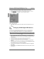
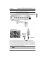
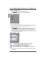
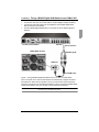
User Guide
control
BX600 Digital KVM Switch
Keyboard/Video/Mouse Switch
590-673-501A
English
2
USA Notification
Warning: Changes or modifications to this unit not expressly approved by the party
responsible for compliance could void the user’s authority to operate the equipment.
Note: This equipment has been tested and found to comply with the limits for a
Class A digital device, pursuant to Part 15 of the FCC Rules. These limits are
designed to provide reasonable protection against harmful interference when the
equipment is operated in a commercial environment. This equipment generates, uses
and can radiate radio frequency energy and, if not installed and used in accordance
with the instruction manual, may cause harmful interference to radio communications. Operation of this equipment in a residential area is likely to cause harmful
interference in which case the user will be required to correct the interference at his
own expense.
Canadian Notification
This Class A digital apparatus complies with Canadian ICES-003.
Cet appareil numérique de la classe A est conforme à la norme NMB-003 du
Canada.
Japanese Notification
Korean Notification
BX600 Digital KVM Switch
Edition September 2006
Comments... Suggestions... Corrections
The User Documentation Department would like to know your opinion of this manual.
Your feedback helps us optimize our documentation to suit your individual needs.
Contact information is included in the back of the manual.
Certified documentation
according to DIN EN ISO 9001:2000
To ensure a consistently high quality standard and user-friendliness, this documentation
was created to meet the regulations of a quality management system which complies
with the requirements of the standard DIN EN ISO 9001:2000.
Copyright and Trademarks
Copyright © 2006 Fujitsu Siemens Computers GmbH.
All rights reserved.
Delivery subject to availability; right of technical modifications reserved.
All hardware and software names used are trademarks of their respective
manufacturers.
Contents
1
1.1
1.1.1
1.1.2
1.1.3
1.1.4
1.1.5
1.1.6
1.1.7
1.2
2
2.1
2.2
2.2.1
3
3.1
3.2
3.2.0.1
3.2.0.2
3.3
3.4
3.4.1
3.4.2
3.4.3
3.4.4
3.5
3.6
4
4.1
4.2
4.2.1
4.2.2
4.2.3
4.2.4
4.2.5
4.2.6
4.2.7
4.2.8
4.2.9
590-673-501A
Product Overview .................................................................................... 1
Features and Benefits ............................................................................... 1
OSCAR Graphical User Interface.............................................................. 2
Network Connectivity................................................................................. 2
Control of Virtual Media ............................................................................. 2
Security ..................................................................................................... 2
Scanning ................................................................................................... 2
Identify Server Modules............................................................................. 2
Tiering ....................................................................................................... 2
Notational Conventions ............................................................................. 2
Installation ............................................................................................... 5
Configuring the BX600 Digital KVM Switch ............................................... 5
Setting Up a BX600 Digital KVM Switch in Tiers....................................... 6
Tiering a BX600 Digital KVM Switch from a KVMs3-1621 or
KVMs2-0411 Console Switch .................................................................... 8
Analog Operation .................................................................................. 11
Controlling Your System.......................................................................... 11
Viewing and Selecting Slots and Server Modules ................................... 11
Selecting Server Modules ....................................................................... 12
Soft Switching.......................................................................................... 12
OSCAR Navigation Basics ...................................................................... 13
Configuring OSCAR ................................................................................ 14
Assigning Server Module Names ............................................................ 15
Changing the Display Behavior ............................................................... 16
Controlling the Status Flag ...................................................................... 17
Setting Console Security ......................................................................... 18
Displaying Version Information................................................................ 21
Scanning Your System ............................................................................ 21
Digital Operation ................................................................................... 25
Accessing the BX600 Digital KVM Switch through the
Fujitsu Siemens Management Blade (MMB) ........................................... 25
Using the Video Viewer ........................................................................... 26
Interacting With the Server Being Viewed ............................................... 26
Viewer Window Features......................................................................... 27
Expanding and Refreshing Your Viewer.................................................. 27
Adjusting the Viewer Window ................................................................. 28
Adjusting Keyboard Macros .................................................................... 28
Setting a Keystroke Prefix ....................................................................... 28
Adjusting Mouse Acceleration ................................................................. 28
Adjusting the Video Quality ..................................................................... 28
Manual Video Adjust Dialog Box Options................................................ 29
Contents
4.2.10
4.2.11
4.2.12
4.2.13
4.3
4.3.1
4.3.1.1
4.3.1.2
4.3.1.3
5
5.1
5.2
5.3
5.4
5.5
5.6
6
6.1
6.2
6.3
6.4
6.4.1
590-673-501A
Minimizing Remote Video Session Discoloration .................................... 29
Improving Screen Background Color Display.......................................... 30
Improving Mouse Performance ............................................................... 30
Create Snapshot Images......................................................................... 31
Virtual Media ........................................................................................... 31
Virtual Media Dialog Box ......................................................................... 31
Mapping a Generic Mass Storage Device ............................................... 32
Mapping a CD/DVD Device ..................................................................... 33
Viewing the Mapped Device Status......................................................... 33
BX600 Graphical User Interface ........................................................... 35
DKVM Blade Folder Contents ................................................................. 35
Blade Info ................................................................................................ 35
Network Configuration ............................................................................. 36
Console Redirection ................................................................................ 37
Virtual Media ........................................................................................... 38
FW Update .............................................................................................. 38
Appendices ............................................................................................ 39
Technical Publications............................................................................. 39
Minimum Requirements for Video Viewer and Virtual Media Interface ... 39
OSCAR Refresh Rates............................................................................ 40
Technical Support ................................................................................... 41
Before you call......................................................................................... 41
1
Product Overview
1.1
Features and Benefits
The Fujitsu Siemens BX600 Digital KVM Switch is integrated in your Fujitsu Siemens
BX600 blade chassis. It allows you to manage many server modules through a single
keyboard, monitor, and mouse. In addition, through virtual media, you can control your
remote servers as if you were physically present.
You can also connect cables from the BX600 Digital KVM Switch to a KVM appliance
such as the Fujitsu Siemens s3-1621 Console Switch. This capability allows you to
create large combinations of servers and switches that you can manage from a common
access point or over your IP network.
Ethernet Port
BX600 Digital
KVM Switch
Local KVM Port
BX600 Blade Chassis
Local KVM Cable
Figure 1: BX600 Digital KVM Switch
590-673-501A
1
OSCAR Graphical User Interface
1.1.1
Product Overview
OSCAR Graphical User Interface
Select the server you would like and then manage it using the On Screen Configuration
and Activity Reporting (OSCAR) interface. OSCAR’s intuitive menus make managing
your BX600 Digital KVM Switch system easy.
1.1.2
Network Connectivity
Using an ethernet connection, you can attach your BX600 Digital KVM Switch to your
network, allowing you to control the blade servers and any attached virtual media
appliances remotely.
1.1.3
Control of Virtual Media
The BX600 Digital KVM Switch allows you to view, move, or copy data from your client
machine to any blade server. This feature enables you to manage remote systems by
allowing you to install operating systems, recover hard drives, and back up servers, to
name a few examples.
1.1.4
Security
OSCAR allows you to protect your system with a screen saver password. After an
amount of time that you define, the screen saver mode engages and access is
prohibited until you enter the appropriate password to reactivate your system.
1.1.5
Scanning
When in Scan Mode, OSCAR allows you to visually monitor server modules by
displaying them one at a time, for the amount of time you specify.
1.1.6
Identify Server Modules
Through OSCAR, you can easily assign names to server modules for your convenience.
(By default all server modules are given the name Slot followed by the slot number.)
1.1.7
Tiering
The BX600 Digital KVM Switch can be set up in tiers from an existing Fujitsu Siemens
KVM switch. The server modules can then be accessed through the software of the
Fujitsu Siemens KVM switch.
1.2
Notational Conventions
The following notational conventions are used in this manual:
Bold
This indicates emphasis in the text.
Key
This indicates keys or key combinations in continuous text.
Italics
This indicates commands, file names, menu names and inputs in
continuous text.
This indicates additional information and tips.
2
590-673-501A
Product Overview
Title
Notational Conventions
This indicates information, which if not heeded, may jeopardize your
health, the functioning of your system or the security of your data.
This indicates a step that you have to perform.
- and •
These characters symbolize itemized lists.
Bold
monospace
font
This indicates user inputs in examples.
590-673-501A
3
Notational Conventions
4
Product Overview
590-673-501A
2
Installation
You can deploy the BX600 Digital KVM Switch Module into most existing KVM
infrastructures. In addition, you can set up the BX600 Digital KVM Switch in tiers from
Fujitsu Siemens branded KVM appliances such as the Fujitsu Siemens s3-1621
Console Switch and analog s2-0801 and s2-1602 switches. It can also be tiered from
other industry products that support the OSCAR interface.
2.1
Configuring the BX600 Digital KVM Switch
Before using the BX600 Digital KVM Switch or configuring it into tiers, you must first set
it up for basic use. Figure 2 displays a basic configuration for the BX600 Digital KVM
Switch.
To connect the BX600 Digital KVM Switch:
Connect the local KVM cable to the appropriate port on the BX600 Digital KVM
Switch.
Connect the keyboard, monitor, and mouse to the local KVM cable.
Monitor
Keyboard
Mouse
BX600 Blade Chassis
Local KVM Cable
Figure 2: BX600 Digital KVM Switch Basic Configuration
590-673-501A
5
Setting Up a BX600 Digital KVM Switch in Tiers
Installation
To display the BX600 Digital KVM Switch Main dialog box by slot order:
Press Print Screen to launch OSCAR, the BX600 Digital KVM Switch interface.
Click Setup and then click Menu. The Menu dialog box appears.
Figure 3: Menu Dialog Box
Select Slot to display servers by slot number. Type a screen delay time of 1 second.
Click OK.
2.2
Tiers
Setting Up a BX600 Digital KVM Switch in
You can set up your BX600 Digital KVM Switch in tiers from our KVM appliances.
To connect the BX600 Digital KVM Switch to the supported KVM appliance:
NOTE: The supported KVM appliances can be: KVMs1-1602, KVMs2-0801, KVMs2-0411 or KVMs3-1621. Tiering
is limited to 2 levels: Level 1 is the BX600 Digital KVM switch. Level 2 is any of the KVM appliances mentioned
above.
6
Place the BX600 blade chassis and the KVM appliance in the desired location.
Fujitsu Siemens recommends powering off and unplugging both appliances before
connecting them.
Connect the keyboard, video, and mouse cable to the KVM appliance.
Connect the other end of this cable to the Local KVM cable.
Connect the Local KVM cable to the KVM port of the BX600 Digital KVM Switch
(Figure 4).
Connect the power cords for both the KVM appliance and the BX600 blade chassis
to the appropriate socket on the back of the appliance.
Connect both the KVM appliance and the BX600 blade chassis to an appropriate
power supply.
Turn the power on for the BX600 blade chassis first; then turn the power on for the
KVM appliance.
590-673-501A
Installation
Setting Up a BX600 Digital KVM Switch in Tiers
NOTE: If the KVM appliance is powered on before the BX600 blade chassis, it may result in only 1 blade sever
displaying in the KVM appliance interface instead of 10.
NOTE: In addition to the steps outlined above, some KVM appliances may require you to perform additional steps
to ensure that the BX600 Digital KVM Switch blade servers appear in the KVM appliance interface. Please read
your KVM appliance documentation for additional information.
KVMs2 or KVMs3 Appliance
Keyboard, Video, and
Mouse Interconnecting
Cable
BX600 Blade chassis
BX600 Digital
KVM Switch
Local KVM Cable
Figure 4: BX600 Digital KVM Switch tiered from a KVMs2-1602 or KVMs2-0801
Before connecting your BX600 Digital KVM Switch to a supported KVM appliance, you
must ensure that it has been set to display in slot order and that the Screen Delay Time
is set to 1 or more seconds. See “Analog Operation” on page 11. for more information.
Once in slot order, it is possible for you also to set a Screen Delay Time that allows you
to soft switch to a server without launching OSCAR.
NOTE: Soft switching allows you to switch servers using a hot key sequence. You can soft switch to a server by
pressing Print Screen and then typing the first few characters of its name or number. If you have a Delay Time set
and you press the key sequences before that time has elapsed, OSCAR will not display, allowing you more agility.
590-673-501A
7
Tiering a BX600 Digital KVM Switch from a KVMs3-1621 or
To configure the KVM appliance:
Press Print Screen to open the OSCAR Main dialog box.
Click Setup then click Devices and then click Device Modify.
Figure 5: Device Modify Dialog Box
Select the 10-port option to match the number of slots in the BX600 blade chassis.
If the 10-port option is not available, select the 16-port option.
Click OK to exit OSCAR.
Press Print Screen to verify that the settings have taken effect. The slot number of
the blade to which the BX600 Digital KVM Switch is now attached should be
expanded to display each of the slot locations of the servers in the BX600 blade
chassis. For example, if the BX600 Digital KVM Switch is attached to slot 1, it would
now be displayed as 01-01 to 01-10.
Figure 6: Main Dialog Box.
2.2.1
Tiering a BX600 Digital KVM Switch from a
KVMs3-1621 or KVMs2-0411 Console Switch
To tier a BX600 Digital KVM Switch from an Fujitsu Siemens s3-1621 Console
Switch:
8
Connect one end of a CAT5 cable to an ARI port on the Fujitsu Siemens s3-1621
Console Switch.
590-673-501A
Installation Tiering a BX600 Digital KVM Switch from a KVMs3-1621
Connect the other end of the CAT5 cable to a KVM Intelligent Adaptor (KVM-IA).
Connect the local KVM cable to the local KVM port of the BX600 Digital KVM
Switch and then to the KVM-IA.
Once the BX600 Digital KVM Switch is connected, the server blades appear in
OSCAR.
s3-1621 Console Switch
ARI Port
Server Interface
BX600 Blade Chassis
PS/2 Dongle/IA
KVM Port
Local KVM Cable
Figure 7: Tiering a BX600 Digital KVM Switch from an s3-1621 Console Switch
Once connected, the s3-1621 Console Switch will automatically configure the slots in
the KVM menu. When the local system is set up, you will need to resynchronize the
server list in the s3-1621 Console Switch software in order to see the list of BX600 blade
chassis server blades. See your s3-1621 Console Switch documentation.
NOTE: With the KVMs3-1621 cascaded above the BX600 Digital KVM switch, you cannot attach virtual media via
the KVMs3-1621 to the BX600 server blades.
590-673-501A
9
Tiering a BX600 Digital KVM Switch from a KVMs3-1621 or
10
590-673-501A
3
Analog Operation
3.1
Controlling Your System
The BX600 Digital KVM Switch uses the intuitive menus of the OSCAR interface to
allow you to select server modules and configure your system.
3.2
Viewing and Selecting Slots and Server
Modules
Use the Main dialog box to view, configure, and control server modules connected to the
BX600 Digital KVM Switch. You can view your server modules by name or by slot, but
by default, you will see a Name list when you first launch OSCAR.
To access the Main dialog box:
Press Print Screen to launch OSCAR. The Main dialog box appears.
-orIf a password has been assigned, the Password dialog box appears. Type your
password and click OK.
The Main dialog box appears. For more information, see “Setting Console Security”
on page 18.
Figure 8: Example of Configured Main Dialog Box
NOTE: To launch OSCAR, you can also press the Ctrl key twice within one second. You can use this key sequence
in any place you see Print Screen throughout this User's Guide.
OSCAR indicates the status of server modules in your system in the far right column of
the Main dialog box. Table 1 describes the status symbols.
590-673-501A
11
Viewing and Selecting Slots and Server Modules Analog Operation
Symbol
Description
Server Module is online
PS/2 subsystem firmware is upgrading
Server Module is offline or is not operating properly
User connection
Table 1: OSCAR Status Symbols
3.2.0.1
Selecting Server Modules
When you select a Server Module, the BX600 Digital KVM Switch reconfigures the
keyboard and mouse to the proper settings for that Server Module.
To select server modules:
Double-click the Server Module name or slot number.
-orIf the display order of your Server Module list is by slot (Slot is depressed), type the
slot number and press Enter.
-orIf the display order of your Server Module list is by name (Name is depressed), type
the first few letters of the name of the Server Module to establish it as unique, and
press Enter twice.
To select the previous Server Module:
Press Print Screen and then Backspace. This key combination toggles you
between the previous and current connections.
To disconnect the analog user from a Server Module:
Press Print Screen and then Alt + Ø. This leaves you in a free state, with no Server
Module selected. The status flag on your desktop, if active, displays Free.
3.2.0.2
Soft Switching
Soft switching is the ability to switch server modules using a hot key sequence. You can
soft switch to a Server Module by pressing Print Screen and then typing the first few
characters of its name or number. If you have a Delay Time set and you press the key
sequences before that time has elapsed, OSCAR will not display.
To configure OSCAR for soft switching:
12
Press Print Screen to launch OSCAR. The Main dialog box appears.
590-673-501A
Analog Operation
OSCAR Navigation Basics
Click Setup and then click Menu. The Menu dialog box appears.
Select Name or Slot for the Display/Sort Key.
For Delay Time, type the number of seconds of delay desired before the Main dialog box is displayed after Print Screen is pressed.
Click OK.
To soft switch to a Server Module:
To select a Server Module, press Print Screen. If the display order of your Server
Module list is by slot as chosen above in step 3 (Slot is depressed), type the slot
number and press Enter.
-orIf the display order of your Server Module list is by name as chosen above in step 3
(Name is depressed), type the first few characters of the name of the Server
Module to establish it as unique and press Enter.
To switch back to the previous Server Module, press Print Screen then Backspace.
3.3
OSCAR Navigation Basics
Table 2 describes how to use the keyboard and mouse to navigate OSCAR.
Keystroke
Result
Print Screen or
Ctrl
Opens OSCAR. Press Print Screen twice (or Ctrl twice) to open
OSCAR on the currently selected device.
F1
Opens the Help screen for the current dialog box.
Escape
Closes the current dialog box without saving changes and
returns to the previous one.
In the Main dialog box, it closes OSCAR and returns to the
selected Server Module.
In a message box, it closes the pop-up box and returns to the
current dialog box.
Alt
Opens dialog boxes, selects or checks options and executes
actions when used in combination with underlined letters or
other designated characters.
Alt+X
Closes current dialog box and returns to the previous one.
Alt+O
Clicks OK, then returns to the previous dialog box.
Enter
Completes the switch operation in the Main dialog box and exits
OSCAR.
Table 2: Keyboard and Mouse Navigation
590-673-501A
13
Configuring OSCAR
Analog Operation
Keystroke
Result
Single-click Enter
In a text box, it selects the text for editing and enables the leftarrow and right-arrow keys to move the cursor. Press Enter
again to quit the edit mode.
Print Screen,
Backspace
Toggles back to previous selection if no other keystrokes have
been typed.
Print Screen, Alt+Ø Immediately disconnects the analog user from a Server Module;
no Server Module is selected. Status flag displays Free. (This
only applies to the Ø on the keyboard and not the keypad.)
Print Screen,
Pause
Immediately turns on screen saver mode and prevents access
to that particular console, if it is password protected.
Up/Down Arrows
Moves the cursor from line to line in lists.
Right/Left Arrows
When editing a text box, these keys move the cursor within the
column.
Home/End
Moves the cursor to the top or bottom of a list.
Backspace
Erases characters in a text box.
Delete
Deletes characters in a text box.
Numbers
Type from the keyboard or keypad.
Caps Lock
Disabled. Use the Shift key to change case.
Table 2: Keyboard and Mouse Navigation (Continued)
3.4
Configuring OSCAR
You can configure your BX600 Digital KVM Switch from the Setup menu within OSCAR.
Click Names when initially setting up your BX600 Digital KVM Switch system to identify
server modules by unique names. Select the other setup features to manage routine
tasks for your server modules from the OSCAR menu.
To access the Setup menu:
Press Print Screen to launch OSCAR. The Main dialog box appears.
Click Setup. The Setup dialog box appears.
14
590-673-501A
Analog Operation
Assigning Server Module Names
Figure 9: Setup Dialog Box
3.4.1
Assigning Server Module Names
Use the Names dialog box to identify server modules by name rather than by slot
number. The Names list is always sorted by slot order.
To access the Names dialog box:
Press Print Screen. The Main dialog box will appear.
Click Setup and then click Names. The Names dialog box appears.
Figure 10: Names Dialog Box
NOTE: If the BX600 Digital KVM Switch System discovers new server modules, the on-screen list will automatically
update. The mouse cursor will change into an hourglass during the update and the system will not accept mouse or
keyboard input.
NOTE: The BX600 Digital KVM Switch stores the Server Module names. If you move a Server Module to a new slot
or chassis, the name will not move with it, so the module must be reassigned a name in the new location.
To assign names to server modules:
In the Names dialog box, select the name or slot number you wish to change and
click Modify. The Name Modify dialog box appears.
590-673-501A
15
Changing the Display Behavior
Analog Operation
Figure 11: Name Modify Dialog Box
Type a name in the New Name field. Names of server modules may be up to 15
characters long. Allowable characters include: A-Z, a-z, Ø-9, space and hyphen.
Click OK to transfer the new name to the Names dialog box. Your selection is not
saved until you click OK in the Names dialog box.
Repeat steps 1-3 for each Server Module in the system.
Click OK in the Names dialog box to save your changes.
-orClick X or press Escape to exit the dialog box without saving changes.
3.4.2
Changing the Display Behavior
Use the Menu dialog box to change the display order of server modules and set a
screen delay time for OSCAR.
To access the Menu dialog box:
Press Print Screen to launch OSCAR. The Main dialog box appears.
Click Setup and then click Menu. The Menu dialog box appears.
Figure 12: Menu Dialog Box
To choose the display order of server modules in the Main dialog box:
16
Select Name to display server modules alphabetically by name.
590-673-501A
Analog Operation
Controlling the Status Flag
-orSelect Slot to display server modules numerically by slot number.
Click OK.
To set a screen delay time for OSCAR:
Type in the number of seconds (Ø-9) you want to delay display of OSCAR after you
press Print Screen. Entering Ø will instantly launch OSCAR with no delay.
Click OK.
Setting a time to delay display of OSCAR allows you to complete a soft switch without
OSCAR displaying. To perform a soft switch, see “Soft Switching” on page 12.
3.4.3
Controlling the Status Flag
The status flag displays on your desktop and shows the name of the selected Server
Module or the status of a slot. Use the Flag dialog box to configure the flag to display by
Server Module name, or to change the flag color, opacity, display time, and location on
the desktop.
Flag
Description
Flag type by name.
Flag indicating that the user has been
disconnected from all systems.
Table 3: OSCAR Status Flags
To access the Flag dialog box:
Press Print Screen. The Main dialog box will appear.
Click Setup and then click Flag. The Flag dialog box appears.
Figure 13: Flag Dialog Box
590-673-501A
17
Setting Console Security
Analog Operation
To determine how the status flag is displayed:
Select Displayed to show the flag all the time or select Displayed and Timed to
display the flag for only five seconds after switching.
NOTE: If only Timed is selected the flag will not be displayed at all.
Select a flag color in Display Color. The flag numbers represent Flag 1, black; Flag
2, red, Flag 3, blue; and 4, purple.
In Display mode, select Opaque for a solid color flag or select Transparent to see
the desktop through the flag.
To position the status flag on the desktop:
a. Click Set Position to gain access to the Position Flag screen.
b. Left-click on the title bar and drag to the desired location.
c. Right-click to return to the Flag dialog box.
Figure 14: Position Flag
NOTE: Changes made to the flag position are not saved until you click OK in the Flag dialog box.
Click OK to save settings.
-orClick X to exit without saving changes.
3.4.4
Setting Console Security
OSCAR enables you to set security on your BX600 Digital KVM Switch console. You
can establish a screen saver mode that engages after your console remains unused for
a specified delay time. Once engaged, your console will remain locked until you press
any key or move the mouse. You will then need to type in your password to continue.
Use the Security dialog box to lock your console with password protection, set or
change your password, and enable the screen saver.
To access the Security dialog box:
Press Print Screen. The Main dialog box will appear.
Click Setup and then click Security. The Security dialog box appears.
NOTE: If a password has been previously set, the user will have to enter the password before being able to access
the Security dialog box.
18
590-673-501A
Analog Operation
Setting Console Security
Figure 15: Security Dialog Box
To set or change the password:
CAUTION: There is no master password. The BX600 appliance must be sent to Fujitsu Siemens in the case of a
lost password.
Single-click and press Enter or double-click in the New text box.
Type the new password in the New text box and press Enter. Passwords require 5
to 12 characters and must include at least one letter and one number. Passwords
are also case sensitive. Legal characters are: A-Z, a-z, and 0-9.
NOTE: You can leave the New text box and the Repeat text box empty, if you do not want a password. (See “To
remove password protection from your console:” on page 20.)
In the Repeat box, type the password again and press Enter.
Click OK if you only want to change your password, and then close the dialog box.
To password protect your console:
Set your password as described in the previous procedure.
Select Enable Screen Saver.
Type the number of minutes for Inactivity Time (from 1 to 99) to delay activation of
password protection and the screen saver feature.
For Mode, select Energy if your monitor is ENERGY STAR™ compliant; otherwise
select Screen.
CAUTION: Monitor damage can result from the use of Energy mode with monitors not compliant with ENERGY
STAR™.
(Optional) Click Test to activate the screen saver test which lasts 10 seconds then
returns you to the Security dialog box.
Click OK.
To log in to your console:
Press Print Screen to launch OSCAR. The Password dialog box appears.
Type your password and then click OK.
The Main dialog box appears if the password was entered properly.
590-673-501A
19
Setting Console Security
Analog Operation
To automatically log out of a Server Module when inactive:
In the Main dialog box, click Setup and then click Security. If you have password
protection, the Password dialog box appears.
Type your password, and then click OK. The Security dialog box appears.
In the Inactivity Time field, enter the length of time you want to stay connected to a
Server Module before it automatically disengages you.
Click OK.
To remove password protection from your console:
In the Main dialog box, click Setup and then click Security. The Password dialog
box appears.
Type your password, and then click OK.
In the Security dialog box, single-click and press Enter or double-click in the New
field. Leave the box blank. Press Enter.
Single-click and press Enter or double-click in the Repeat box. Leave the field
blank. Press Enter.
Click OK if you only want to eliminate your password.
To enable the screen saver mode with no password protection:
CAUTION: There is no master password. The BX600 appliance must be sent to Fujitsu Siemens in the case of a
lost password.
If your console does not require a password to gain access to the Security dialog
box, continue to the next step.
- or If your console is password protected, see the previous procedure, To remove
password protection from your console:
Select Enable Screen Saver.
Type the number of minutes for delay time (from 1 to 99) that you want to delay activation of the screen saver.
Choose Energy if your monitor is ENERGY STAR™ compliant; otherwise select
Screen.
CAUTION: Monitor damage can result from the use of Energy mode with monitors not compliant with ENERGY
STAR™.
(Optional) Click Test to activate the screen saver test which lasts 10 seconds then
returns you to the Security dialog box.
Click OK.
NOTE: Activation of the screen saver mode disconnects the user from a Server Module; no Server Module is
selected. The status flag displays Free.
To exit the screen saver mode:
Press any key or move your mouse. The Main dialog box appears.
20
590-673-501A
Analog Operation
Displaying Version Information
To turn off the screen saver:
In the Security dialog box, clear Enable Screen Saver.
Click OK.
To immediately turn on the screen saver:
Press Print Screen, then press Pause.
NOTE: Enable Screen Saver must be selected in the Security dialog box.
3.5
Displaying Version Information
Use the Version dialog box to display the BX600 Digital KVM Switch firmware, hardware
and FPGA versions, and to identify the language and keyboard configuration. For
optimum performance, keep your firmware current. For more information on updates,
see “OSCAR Refresh Rates” on page 40.
To display version information:
Press Print Screen. The Main dialog box will appear.
Click Commands and then click Display Versions. The Version dialog box
appears. The top half of the box lists the subsystem versions in the BX600 Digital
KVM Switch.
Figure 16: Version Dialog Box
Click X or press Escape to close the Version dialog box.
3.6
Scanning Your System
In scan mode, the BX600 Digital KVM Switch automatically scans from slot to slot
(Server Module to Server Module). You can scan up to 10 server modules by specifying
which server modules you want to scan and the number of seconds that each Server
Module will display.
To add server modules to the Scan list:
If OSCAR is not open, press Print Screen. The Main dialog box will appear.
Click Setup and then click Scan. The Scan dialog box appears.
590-673-501A
21
Scanning Your System
Analog Operation
Figure 17: Scan Dialog Box
The dialog box contains a listing of all the server modules attached to your unit.
Click to enable the check box next to the server modules you wish to scan.
-orDouble-click on a Server Module's name or slot.
-orPress Alt+ the number of the Server Module you wish to scan. You can select up to
10 server modules.
In the Scan Time field, type the number of seconds (from 3 to 99) of desired time
before the scan moves to the next Server Module in the sequence.
Click OK.
To remove a Server Module from the Scan list:
In the Scan dialog box, click to disable the check box next to a Server Module to be
removed.
-orDouble-click on a Server Module's name or slot.
-orClick Clear to remove all server modules from the Scan list
Click OK.
To start the scan mode:
Press Print Screen. The Main dialog box will appear.
Click Commands. The Command dialog box appears.
22
590-673-501A
Analog Operation
Scanning Your System
Figure 18: Command Dialog Box
3 Select Scan Enable in the Command dialog box.
To cancel scan mode:
Select a Server Module if OSCAR is open.
-orMove the mouse or press any key on the keyboard if OSCAR is not open. Scanning
will stop at the currently selected Server Module.
-orPress Print Screen. The Main dialog box will appear.
Click Commands. The Command dialog box appears.
Clear Scan Enable.
590-673-501A
23
Scanning Your System
24
Analog Operation
590-673-501A
4
Digital Operation
The BX600 Digital KVM Switch allows you to manage both blade servers and virtual
media from a remote location. Using the Video Viewer, you can view and manage any of
ten blade servers remotely in exactly the same way that you would if you were sitting in
front of them. Using the Virtual Media dialog box, you can manage virtual media
sessions allowing you to remotely perform server backups, recovery operations, and
operating system installation to name a few examples. For each of these operations,
you go through the Fujitsu Siemens Management Blade (MMB).
Your client machine must meet minimum requirements to access the MMB, the video
viewer or manipulate virtual media (See Appendix B).
4.1
Accessing the BX600 Digital KVM Switch
through the Fujitsu Siemens Management Blade
(MMB)
Point your browser to the IP address of the MMB to access the BX600 Digital KVM
Switch. You may then access the video viewer and manipulate virtual media.
Figure 19: Fujitsu Siemens Management Blade (MMB) Home Page
To access the Video Viewer application:
From your browser, type in the correct URL to bring up the MMB interface.
590-673-501A
25
Using the Video Viewer
Digital Operation
Click on the plus sign (+) next to the DKVM folder in the left column to display the
folder’s contents.
On the left side, select Console Redirection.
On the right side, select the Server Blade from the drop-down list.
Click on Launch.
4.2
Using the Video Viewer
Once you have selected Console in the MMB menu, you may select the server you
would like to interact with.
To access a server:
Click the Servers button in the list of servers.
Click the Select Server button. The Launch Application button will become active.
Click the Launch Application button. The server’s desktop will appear.
4.2.1
Interacting With the Server Being Viewed
Once you have connected to a server, you will see the desktop window of the server on
your screen. This opens in a separate window. You will see two cursors: the local cursor
and the server’s cursor. You may need to align these if they do not move together or
adjust the video if they seem to jump about. From this window, you will be able to
access all the normal functions of this server as if you were sitting right in front of it. You
may also perform Viewer-specific tasks such as sending special Macro commands to
the server.
26
590-673-501A
Digital Operation
4.2.2
Viewer Window Features
Viewer Window Features
Figure 20: Video Viewer Application
4.2.3
Expanding and Refreshing Your Viewer
You can adjust your view of the remote system’s monitor using the buttons at the bottom
of the Viewer window. The buttons allow you to set video adjustments, refresh the
screen, capture screen images, get help and close the Video Viewer application. There
are also some check boxes and drop-down lists that let you pass special keystrokes to
the remote system without affecting your local workstation.
To set video adjustments:
Click Calibrate on the viewer toolbar.
This automatically calibrates and sets the video adjustments. You also have the
option to launch a manual video adjustment dialog box. See “Manual Video Adjust
Dialog Box Options” on page 29.
To refresh the screen image in the Video Viewer:
Click Refresh on the viewer toolbar.
To capture a screen image from the Video Viewer:
Click Create Snapshot on the viewer toolbar.
To get help:
Click Help on the viewer toolbar.
590-673-501A
27
Adjusting the Viewer Window
Digital Operation
To close the Video Viewer application:
Click Close on the viewer toolbar.
4.2.4
You can adjust both the size and quality of the server’s Viewer. You can also
expand your Viewer to fit the entire screen or refresh the view at any time.
4.2.5
Adjusting the Viewer Window
Adjusting Keyboard Macros
Allows you to select and type a number of keystroke combinations that cannot be
typed using your local keyboard without affecting your local system.
To use any one of the keystroke combinations listed:
From the Keystroke Macros list, select the macro you want to send.
Click Send. The keystroke macro is sent to the remote system.
4.2.6
Setting a Keystroke Prefix
Click to enable one or more of the Keystroke Prefix check boxes to enable you to
select a key or key combination that acts as a previous keystroke to your actual
keystrokes.
4.2.7
Adjusting Mouse Acceleration
The Mouse Acceleration list allows you to select the operating system you want to view.
Select the appropriate operating system to optimize console redirection mouse
performance. You can select None for Windows and most other operating systems and
Linux for the Linux operating system.
4.2.8
Adjusting the Video Quality
The Viewer offers both automatic and manual video adjustment capability. Generally,
the Automatic Video Adjustment will optimize the video for the best possible view.
However, you may wish to alter the video for your specific needs. Use the slider bar for
fine adjustments, and the Plus (+) and Minus (-) buttons for small, incremental
adjustments.
NOTE: Only 7-bit color is supported.
28
590-673-501A
Digital Operation
4.2.9
Manual Video Adjust Dialog Box Options
Manual Video Adjust Dialog Box Options
A
B
C
D
E
F
G
H
I
J
K
L
M
Figure 21: Manual Video Adjust Dialog Box
A Pixel Sampling Fine Adjustment
B Image Capture Horizontal Position
C Image Capture Vertical Position
D Contrast
E Brightness
F Pixel Noise Threshold
G Automatic Video Adjustment
H Refresh Image
I Scroll Bar (for active button)
J Three Color Video Test Pattern
K Help Button
L Performance Monitor
M Close Button
To manually adjust the video quality of the Viewer window:
In the Viewer, click Calibrate. The Auto Video Adjust dialog box appears.
Click the Manual Video Adjust button.
Click the icon for the feature you wish to adjust.
Move the slider bar or click Minus (-) or Plus (+) to adjust the parameter one unit at
a time for each icon pressed. The adjustments will display immediately in the
Viewer window.
When finished, click Close to exit the Manual Video Adjust dialog box.
4.2.10
Minimizing Remote Video Session Discoloration
When establishing remote video sessions, pixel discolorations may occur due to
network conditions. This condition occurs most often with a solid color background. This
590-673-501A
29
Improving Screen Background Color Display
Digital Operation
condition is minimized by using a black background. If a color background is used, a
small number of pixels on the screen will be discolored or white.
To minimize remote video pixel discoloration:
In the Viewer, click Calibrate. The Auto Video Adjust dialog box appears.
Click the Manual Video Adjust button.
Choose contrast or brightness.
Adjust the contrast and brightness until the image quality improves.
A noise threshold setting is also available and then Manual Video Adjust for fine
incremental adjustments.
NOTE: Reducing the noise threshold to zero causes constant video refresh, high network usage and a flickering
video. Fujitsu Siemens recommends that the noise threshold be set to the highest level that allows efficient system
performance, while still being able to recover pixel colors over which the mouse cursor travels.
NOTE: When adjusting the noise threshold, use the slider bar for large adjustments and Plus (+) and Minus (-) at
the ends of the slider bar for fine-tuning.
4.2.11
Improving Screen Background Color Display
You may experience inconsistent color display when viewing target servers where
photographic images or color-intense gradient backgrounds have been selected. We
recommend that you select a solid color display background via the operating system
for optimal display quality and performance.
Use the Plus (+) and Minus (-) buttons at the end of the slider bar to fine-adjust the
noise threshold to just above zero.
NOTE: Leaving the noise threshold at zero triggers constant video refresh, resulting in high network usage and a
flickering video. It is recommended that the noise threshold be set at the highest level that allows efficient system
performance, while still being able to recover pixel colors that the mouse cursor travels over.
NOTE: When adjusting the noise threshold, the slider bar can be used for large or very fine adjustments and the
Plus (+) and Minus (-) buttons at either end of the slider bar for small, incremental adjustments.
4.2.12
Improving Mouse Performance
If you are experiencing slow mouse response during a remote video session, you may
want to deactivate the mouse acceleration in the operating system of the target server.
Microsoft Windows XP Default Mouse Drivers:
30
Select Start then select Settings and then select Control Panel.
Double-click the Mouse icon.
Click on the Motion tab.
Adjust mouse speed to the exact midpoint of the slider bar.
In the Acceleration setting, select the Off radio button.
Click OK. Click Mouse Synchronize/Screen Refresh in Video Session Viewer to
resynchronize the mouse.
590-673-501A
Digital Operation
Create Snapshot Images
Intellipoint Drivers (Only for Windows based Operating Systems):
Select Start then select Settings and then select Control Panel.
Double-click the Mouse icon.
Cycle through the tabs until the pointer speed slider is displayed.
Adjust the mouse speed to the exact midpoint of the slider bar.
Click Advanced.
Click the Acceleration check box to turn off acceleration.
Click OK. Click Mouse Synchronize/Screen Refresh in Video Session Viewer to
resynchronize the mouse.
Red Hat Linux:
Select the Mouse settings from the Desktop Controls.
Set Acceleration to 1.0.
Apply the changes and click Mouse Synchronize/Screen Refresh in Video Session Viewer to resynchronize the mouse.
Any Linux Distribution:
Open a Console window in the Desktop.
Enter the following command:
xset m 0
NOTE: On some Linux distributions, this procedure needs to be performed each time you log onto the Desktop.
4.2.13
Create Snapshot Images
The Create Snapshot button captures the current remote system screen to a .jpg file on
the local system. A dialog box is displayed that allows you to save the .jpg file to a
specified location.
4.3
Virtual Media
4.3.1
Virtual Media Dialog Box
The Virtual Media dialog box allows you to map a single generic mass storage device
(or floppy image) and a single CD/DVD device (or CD/DVD image) to a target server.
Once you have selected Virtual in the MMB menu, you may select the server you would
like to interact with.
590-673-501A
31
Virtual Media Dialog Box
Digital Operation
Figure 22: Virtual Media page of the MMB menu
To access a server:
Click the Select Device drop-down list in the list of servers.
Select the server on which you want to attach your virtual media. The launch button
will become active.
Click the Launch button. The Virtual Media dialog box will appear. It will be associated with the server you chose from the drop-down list.
4.3.1.1
Mapping a Generic Mass Storage Device
The Generic Mass Storage Devices or Filesystems panel allows you to select a floppy
drive from a list of all client floppy drives and removable USB drives. You can also select
the Floppy Image option that allows you to browse to the location of your chosen floppy
image file. If you do not want to select either of these options you can select the No
Floppy option.
NOTE: Only one Generic Mass Storage Devices or Filesystems option can be selected at any one time. The
selected generic mass storage device is not mapped until you click Apply.
32
590-673-501A
Digital Operation
Virtual Media Dialog Box
4.3.1.2
Mapping a CD/DVD Device
The CD/DVD Devices or Filesystem panel allows you to select a CD/DVD device from
the attached CD/DVD drives. You can also select the ISO Image option to select a
single CD/DVD image file. If you do not want to select either of these options you can
select the No CD/DVD option.
NOTE: Only one CD/DVD Devices or Filesystem option can be selected at any one time. The selected generic
mass storage device is not mapped until you click Apply.
4.3.1.3
Viewing the Mapped Device Status
The Currently Mapped Drives panel lists the generic mass storage device and CD/DVD
device that are currently mapped. For each mapped device, the target drive, where the
target drive is mapped and the number of bytes read (for that device) are displayed.
Click Details to display or hide this panel.
Figure 23: Virtual Media Dialog Box
590-673-501A
33
Virtual Media Dialog Box
34
Digital Operation
590-673-501A
5
BX600 Graphical User Interface
The Fujitsu Siemens BX600 Digital KVM Switch allows you to access the blades in a
BX600 Blade Server using a Graphical User Interface (GUI).
To access the Fujitsu Siemens Management Blade (MMB) GUI:
Point your browser to the IP address of the MMB to access the BX600 Digital KVM
Switch.
When the Fujitsu Siemens Management Blade GUI is called up, the first screen that
appears has a list of folders in the left hand column that consist of the following:
•
System Property
•
Management Blade
•
Lan Switch Blade
•
DKVM Blade
•
Server Blade
5.1
DKVM Blade Folder Contents
The scope of this chapter will discuss the DKVM Blade folder, its contents and how to
perform the various tasks.
To access the DKVM Blade folder pages:
Click the plus sign (+) next to the DCVM folder icon in the left column of the GUI
screen.
The DKVM Blade folder contains the following pages:
•
Blade Info
•
Network Configuration
•
Console Redirection
•
Virtual Media
•
Firmware Update
5.2
Blade Info
Blade Info is a page in the folder that displays the information about the BX600 Digital
KVM switch that is installed in the BX600 blade server.
To access the Blade Info page:
Select Blade Info from inside the DKVM Blade folder in the left column.
When this page is selected, the BX600 reads the blade information from the BX600
Digital KVM switch. This page shows the following items:
•
DKVM blade Manufacture
•
DKVM blade Manufacture Date
•
DKVM blade Serial Number
•
DKVM blade Product Name
•
DKVM blade Model Name
590-673-501A
35
Network Configuration
•
BX600 Graphical User Interface
DKVM blade Hardware Version
5.3
Network Configuration
In order for you to have GUI access to the BX600 Digital KVM switch, you must assign a
valid IP address to it.
NOTE: If your local area network is configured for DHCP, you should check the DHCP check box and you can skip
the first three steps of the following task.
To configure the BX600 Digital KVM switch with an IP address:
Select Network Configuration from inside the DKVM Blade folder in the left column.
Assign an IP address to the BX600 Digital KVM switch by filling in the boxes in the
KVM IP Address field.
NOTE: The IP address of the BX600 Digital KVM switch must be in the same subnet as the Fujitsu Siemens BX600
Management Blade Module.
Enter the default gateway address by filling in the boxes in the Default Gateway
field.
Enter the network mask by filling in the boxes in the Network Mask field.
If necessary, enter a port address in the Keyboard/Mouse Port field. In most
cases, you can leave this setting at the default value.
If necessary, enter a port address in the Virtual Media Port field. In most cases you
may leave this setting at the default value.
If necessary, enter a port address in the Video Port field. In most cases you may
leave this setting at the default value.
Click on Apply Changes.
A typical network configuration page is shown in the following illustration.
36
590-673-501A
BX600 Graphical User Interface
Console Redirection
Figure 24: DKVM Network Configuration Page of the MMB Menu
5.4
Console Redirection
The Console Redirection page is the page that you use to launch the Video Viewer
application.
To redirect the console to a Video Viewer of your selected blade server:
Select Console Redirection from inside the DKVM Blade folder in the left column.
Select a blade server from the drop-down list in the screen that appears.
Click on Launch.
The Console Redirection page is shown in the following illustration.
Figure 25: Console Redirection Page of the MMB Menu
For details on using the Video Viewer, see “Using the Video Viewer” on page 26.
590-673-501A
37
Virtual Media
5.5
BX600 Graphical User Interface
Virtual Media
The BX600 Digital KVM switch allows you to use media on your local workstation as if it
were installed on the remote blade server. This feature is known as virtual media.
To launch the Virtual Media Dialog Box:
Select Virtual Media from inside the DKVM Blade folder in the left column.
Select a blade server from the drop-down list in the screen that appears.
Click on Launch.
For details on using Virtual Media, see “Virtual Media” on page 31.
5.6
FW Update
You can update the firmware on the BX600 Digital KVM switch from the MMB.
To update BX600 Digital KVM firmware:
Select Firmware Update from inside the DKVM Blade folder in the left column.
Enter the file name in the Image Name field that appears in the right portion of the
MMB page.
Enter the IP address of the TFTP server where the firmware resides by filling in the
boxes in the TFTP Server IP field.
Click on Update Firmware.
Optionally, you may click on Firmware Update Status to see how the firmware
update is progressing.
CAUTION: Never interrupt a firmware update in progress. It can make your BX600 Digital KVM switch
inoperable, and it will be necessary to return it to Fujitsu Siemens for a firmware reinstallation.
The Firmware Update page is shown in the following illustration.
Figure 26: Firmware Update Page of the MMB Menu
38
590-673-501A
6
Appendices
6.1
Technical Publications
Server Module Slots
Number
10
Plug and Play
DDC2B
Video Resolution
Analog Port Maximum
1600x1200@75Hz.
Ethernet Port
Number
1
Connectors
RJ45
Analog Port
Number
1
Type
PS/2 and VGA
Connectors
PS/2 MiniDIN, 15 Pin D
Table 1: Technical Specifications
6.2
Minimum Requirements for Video Viewer
and Virtual Media Interface
Successful operation of the video viewer and the remote client for virtual media requires
the following minimum configuration on the client machine:
•
650 MHz Pentium or equivalent processor
•
128 MB of RAM
•
10 or 100BaseT NIC (100 recommended)
•
xga video with graphics accelerator
•
Desktop size setting of at least 800x600
•
Color palette of at least 256 colors
•
One of the following operating systems:
•
Windows XP Home or Professional Edition, Server Pack 2
•
Windows 2003 Server Standard Enterprise or Web Edition, Service Pack 1
•
Red Hat Enterprise Linux 4 (RHEL4) WS, ES, AS
•
SuSE Linux Enterprise Server 9 (SLES9)
•
Internet Explorer 6.0 SP1 or later web browser (Windows operating systems only)
590-673-501A
39
OSCAR Refresh Rates
•
Appendices
Java JRE version 1.4.2 or later
6.3
OSCAR Refresh Rates
On-Screen Configuration and Activity Reporting interface (OSCAR®) synchronizes to
the following refresh rates.
Resolution
Refresh Rate
Horizontal Frequency
640 x 480
60 Hz
31.5 Khz
640 x 480
72 Hz
37.9 Khz
640 x 480
75 Hz
37.5 Khz
640 x 480
85 Hz
43.3 Khz
800 x 600
60 Hz
37.9 Khz
800 x 600
72 Hz
48.1 Khz
800 x 600
75 Hz
46.9 Khz
800 x 600
85 Hz
53.7 Khz
1024 x 768
60 Hz
48.4 Khz
1024 x 768
72 Hz
56.5 Khz
1024 x 768
75 Hz
60.0 Khz
1024 x 768
85 Hz
68.7 Khz
1152 x 864
75 Hz
67.5 Khz
1280 x 768
60 Hz
60.0 Khz
1280 x 768
85 Hz
85.9 Khz
1280 x 1024
60 Hz
64.0 Khz
1280 x 1024
75 Hz
80.0 Khz
1280 x 1024
85 Hz
91.1 Khz
1600 x 1200
60 Hz
75.0 Khz
1600 x 1200
70 Hz
87.0 Khz
1600 x 1200
75 Hz
93.8 Khz
Table 2: Refresh Rates
40
590-673-501A
Appendices
Technical Support
Resolution
Refresh Rate
Horizontal Frequency
1600 x 1200
85 Hz
106.3 Khz
Table 2: Refresh Rates (Continued)
6.4
Technical Support
Our Technical Support staff is ready to assist you with any installation or operating
issues you encounter with your Fujitsu Siemens product. If an issue should develop,
follow the steps below for the fastest possible service: Check the pertinent section of
this manual to see if the issue can be resolved by following the procedures outlined.
Check our web site at http://www.fujitsu-siemens.com/support and click on Services &
Support. Click helpdesk on the left side of the page for a listing of technical support
phone numbers in your area.
6.4.1
Before you call
Before you call, make sure that you have taken these steps to try to solve the
problem yourself:
•
Check all cables to make sure that they are connected.
•
Check the power switches to make sure that the system and any optional devices
are turned on.
•
Use the troubleshooting information in your system documentation, and use the
diagnostic tools that come with your system.
•
Go to the Fujitsu Siemens support Web site at http://www.fujitsu-siemens.com/
support/ to check for technical information, hints, tips, and new device drivers or to
submit a request for information.
You can solve many problems without outside assistance by following the
troubleshooting procedures that Fujitsu Siemens provides in the online help or in the
documentation that is provided with your Fujitsu Siemens product. If you suspect a
software problem, see the documentation for the operating system or program.
590-673-501A
41
Before you call
42
Appendices
590-673-501A