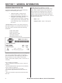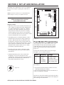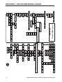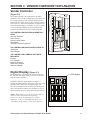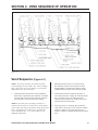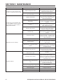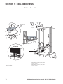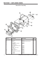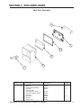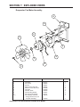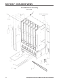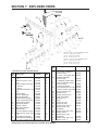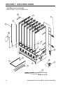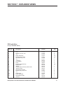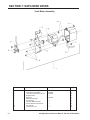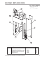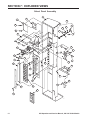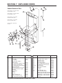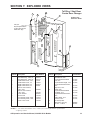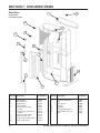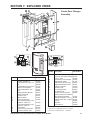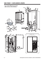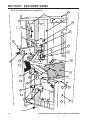
1
Royal Vendors, Inc.
GIII
Operation and Service Manual
230 VAC 50 Hz Models with KO Programming
Manufactured by
Royal Vendors, Inc. • 426 Industrial Boulevard • Kearneysville WV 25430-2776 • USA
R
Telephone +1 304 728 7056 • Fax +1 304 725 4016 • [email protected] • [email protected] • www.royalvendors.com
Royal Vendors, Inc. • 426 Industrial Boulevard • Kearneysville WV 25430-2776 • USA
Customer Service: +1 304 728 7056 or Toll Free (in North America only) 1 800 931 9214 • Fax +1 304 725 4016
E-mail: [email protected]
[email protected]
Website: www.royalvendors.com
2
GIII Operation and Service Manual, 230 VAC 50 Hz Models
TABLE OF CONTENTS
SAfety segment..........................................................................5
Section 1: General Information ................................................ 7
Introduction . .................................................................................. 7
Specifications ................................................................................ 7
Unpacking the Vender.....................................................................7
Capacity......................................................................................... 7
Vender Identification........................................................................8
Section 2: Set-Up and Installation ........................................... 9
Modes of Operation........................................................................ 9
Peripherals....................................................................................10
Moving and Securing the Vender..................................................10
Loading the Vender ..................................................................... 11
Using the HHC to Program The Vender ...................................... 14
Testing the Vender . ..................................................................... 14
Installing the Vender on Location ................................................ 14
Four-Button Programming.............................................................15
KO Programming Flowchart..........................................................16
EMS Software...............................................................................17
Internal (Service) Menu.................................................................17
Error Display Mode (Eror)...........................................................17
Coin Payout Mode (CPO)............................................................19
Tube / Stack Fill Mode (tUFL)......................................................19
Recycler Pay Out (rPO)...............................................................19
Test Vend Mode (tESt)................................................................20
Password Protection (PASS).......................................................21
Cash Counter Display Mode (CASH)..........................................21
Vend Counter Display Mode (SALE)...........................................21
Card Counter Display Mode (CArd)............................................21
Token Counter Display Mode (toKn)...........................................22
Free Vend Accounting Mode (FrEE)............................................22
Selection Price Setting Mode (PrIC)............................................23
Space-to-Sales Programming Mode (StS)..................................23
Machine Configuration Mode (Con)............................................24
Correct Change Only Control Mode (CCOC)..............................26
Preview Data Password Mode (PrEU)........................................26
Language Selection Mode (LAnG)..............................................27
Time/Date Setting Mode (tinE)....................................................27
Lighting Control Mode (Lit)..........................................................29
Refrigeration Control Mode (rFrG)..............................................31
Block Selection 1 and 2 (bLCI & bLC2).......................................33
Discount Setting (dISC)...............................................................35
Manual Switch Over-Ride (OUEr)...............................................36
Set Selection Depth Mode (SdEP)..............................................38
Remote Vend Mechanism Routine (rUnd)...................................38
GIII Operation and Service Manual, 230 VAC 50 Hz Models
3
TABLE OF CONTENTS (continued)
Return To Sales Mode (rtn).........................................................39
External Menu...............................................................................40
Vend Counter Display Mode (SALE)...........................................40
Cash Counter Display Mode (CASH)..........................................40
Error Display Mode (Eror)...........................................................40
Return to Sales Mode (rtn)..........................................................40
Section 3: Vender Component Explanation .......................... 41
Vender Controller ........................................................................ 41
Digital Display . ............................................................................ 41
Door Switch...................................................................................42
Delivery Chute Sensor..................................................................42
Low Voltage Transformer..............................................................42
Selection Switches........................................................................42
Coin Changer................................................................................42
Banknote Acceptor........................................................................42
Debit Card Reader........................................................................42
Vend Rack Assembly.....................................................................43
Vend Rack Components................................................................43
Refrigeration System.....................................................................45
The Electronic Refrigeration Cycle................................................46
Section 4: Vend Sequence of Operation ............................... 47
Vend Sequence ........................................................................... 47
Column Sequencing......................................................................48
Sold Out........................................................................................48
Section 5: Maintenance ...........................................................49
Interconnect Drawing....................................................................49
Controller Board Layout................................................................50
Taking Care of the Vender . ......................................................... 51
Removal of Vender Components ................................................ 52
Troubleshooting . ......................................................................... 57
Refrigeration Flow Chart...............................................................67
Section 6: Optional Equipment .............................................. 68
SECTION 7: Exploded Views ..................................................... 69
4
GIII Operation and Service Manual, 230 VAC 50 Hz Models
SAFETY SEGMENT
ROYAL VENDORS’ COMMITMENT TO
SAFETY
Royal Vendors is committed to safety with all of our
product designs. We are committed to notifying the user
of a possible danger involving the improper handling
or maintenance of our venders. The servicing of any
electrical or mechanical device involves potential
dangers, both to those servicing the equipment and to
users of the equipment. These dangers can occur because
of improper maintenance or usage. The purpose of
this safety segment is to alert everyone servicing Royal
equipment of potentially dangerous areas, and to provide
basic safety guidelines for proper upkeep.
The service manual contains various warnings that
should be carefully read to minimise the risk of personal
injury. This manual also contains service information
to insure that proper methods are followed to avoid
damaging the vender or making it unsafe. It is also
important to understand these warnings provide general
guidance only. Royal could not possibly know, evaluate,
or advise of all of the conceivable ways in which service
might be done. Consequently, Royal cannot predict all
of the possible dangerous results. These outlined safety
precautions are the basis for an effective safety program.
Use these safety measures, along with the service
bulletins, helpful hints and product specification sheets,
when installing or servicing Royal equipment.
We recommend that persons servicing our equipment
maintain a similar commitment to safety. Only personnel
properly trained should have access to the interior
of the vender. This will minimise the potential dangers
that are inherent in electrical and mechanical devices.
Royal has no control over the vender once it leaves the
premises. It is the owner or lessor’s responsibility to
maintain the vender in a safe condition. See installation
insert located in the coin box of a new vender for proper
installation procedures and refer to the service manual
for recommended maintenance procedures. If you have
any questions, please contact the Technical Service
Department at +1 304 728 7056.
SAFETY REGULATIONS
· Read the safety segment before installation or service.
· Test for proper earthing before installing to reduce the
risk of electrical shock and fire.
· Turn off or disconnect power cord from power source
before servicing.
· Only fully trained service technicians should service
vender when vender has power.
· Remove any product before moving a vender.
· Use appropriate equipment when moving a vender.
· Always wear eye protection, and protect your hands,
face, and body when working near the refrigeration
system.
· Use only authorised replacement parts.
· Be aware of inherent dangers in rocking or tipping a
vender.
SECTION I: ELECTRICAL HAZARDS
GENERAL ADVICE
Careless or improper handling of electrical circuits can
result in injury or death. Anyone installing, repairing,
loading, opening, or otherwise servicing a vender should
be aware of this precaution. Apply all of the normal
precautions when handling electrical circuits, such as:
· Refrigeration servicing to be performed by qualified
personnel only.
· Unplug the vender before servicing.
· Replace electrical cords if there is any evidence of
fraying or other damage.
· Keep all protective covers and earthing wires in place.
· Plug equipment into outlets that are properly earthed
and polarised (where applicable), and protected with
fuses or circuit breakers of the correct size.
· All electrical connections must be dry and free of
moisture before applying power.
WARNING: ALWAYS TEST TO VERIFY PROPER
EARTHING PRIOR TO INSTALLATION IN ORDER TO
REDUCE THE RISK OF ELECTRICAL SHOCK AND
FIRE.
GIII Operation and Service Manual, 230 VAC 50 Hz Models
5
SAFETY SEGMENT
SECTION II: ELECTRICAL HAZARDS
A. Servicing with Power Off
For maximum safety, unplug the power cord from the
wall outlet before opening the vender door. This will
remove power from the equipment and avoid electrical
hazards. Service personnel should remain aware of
possible hazards from hot components although electrical
power is off.
B. Servicing with Power On
Some service situations may require access with power
on. Only fully qualified service technicians should
perform power-on servicing. Particular caution is
required in servicing assemblies that combine electrical
power and mechanical movement. Sudden movement
(to escape mechanical action) can result in contact with
live circuits and vice versa. It is therefore important to
maintain maximum clearances from both moving parts
and live circuits when servicing.
WARNINGS:
1. ONLY FULLY TRAINED PERSONNEL SHOULD
ACCOMPLISH SERVICING WITH POWER
ON. SUCH SERVICE BY UNQUALIFIED
INDIVIDUALS CAN BE DANGEROUS.
2. LIGHTING CIRCUITS CAN BE HAZARDOUS.
ALWAYS DISCONNECT FROM POWER SUPPLY
BEFORE REPLACING A BULB OR SERVICING
THE VENDER IN THAT AREA.
3. NEVER USE A HOSE, PRESSURE WASHER
OR ANY CLEANING METHOD THAT COULD
WET ELECTRICAL COMPONENTS. SEE
CLEANING SECTION OF MANUAL FOR
SUGGESTED CLEANING METHODS. IF
WATER CONTAMINATION OF ELECTRICAL
COMPONENTS IS SUSPECTED, USE QUALIFIED
ELECTRICAL TESTING EQUIPMENT AND TEST
METHODS TO ASSURE THAT VENDER IS NOT A
HAZARD BEFORE APPLYING POWER FOR ANY
REASON.
4. CAUTION: REMOVE POWER TO THE
VENDER BEFORE ATTEMPTING ANY SERVICE
INVOLVING THE CHAIN, VEND MOTOR, OR
LEVERS. HAZARD: THE VEND CHAIN IS
CONTROLLED BY A LOW-VOLTAGE, LOWENERGY MOTOR. THE VEND CHAIN MAY BE
ACTIVE WHEN THE DOOR SWITCH IS PUSHED
INTO THE CLOSED POSITION, THE “tESt” MODE
IS USED IN PROGRAMMING, OR AN ACTUAL
VEND IS MADE. NEVER PLACE HANDS INTO
THE DRIVE MECHANISM WHILE THE VENDER
IS ENERGISED. A PAINFUL PINCH IS POSSIBLE,
WHICH MAY RESULT IN CUTS OR BRUISES.
6
GIII Operation and Service Manual, 230 VAC 50 Hz Models
Section 1: General Information
Introduction
This manual contains installation, operation and service
instructions for Royal Vendors’ G-III All-Purpose Vender.
This manual also contains a complete parts catalogue and
electrical wiring diagram for the G-III vender.
Capacity
804
660
Package TypeModelModel
600 mL Plastic Coke
Contour Bottle
360
288
600 mL Plastic Sprite Contour Bottle
360
288
600 mL Plastic
Surge/Bolt Bottle
336
276
600 mL Plastic
Straight Wall Bottle
336
276
Specifications
500 mL Fruitopia
Bottle
336
276
Dimensions.... (804 cap.) 202 cm H x 94 cm W x 86 cm D
(660 cap.) 183 cm H x 94 cm W x 86 cm D
Approximate Empty Weight.................Wide (804) 296 kg
Wide (660) 272 kg
Narrow (550) 243 kg
Capacity.................... (804 cap.) 355 mL cans, 12 columns
(660 cap.) 355 mL cans, 12 columns
Operating Voltage .............................. 230 VAC, 50 Hertz
Amperage Rating.................................................. 5.5 AMP
Charge......................................................... 0.17 kg R134A
Construction................................... Steel cabinet, steel rack
Selections.................................................9 or 13 selections
Altitude Adjustment........................no adjustment required
for the GIII’s Electronic
Cold Control
600 mL Plastic
PowerAde Bottle
372
300
500 / 600 mL Glass
Straight Wall Bottle
324
264
355 mL Can
804
660
16 oz. Can
396
324
10 oz. Bottle
384
312
The G-III is a microprocessor controlled vender which
permits pricing per selection from 0.00 to 99.99. The
G-III vender provides electronic space-to-sales (STS)
programmability and will collect, store and transfer MIS
data fields to a hand-held computer (HHC) or online
device.
NOTE: Since new packaging is constantly being
introduced, this listing may not contain ALL vendible
packages. For the latest information on packages that will
vend in the GIII, please contact Royal Vendors’ Customer
Service Department.
Unpacking the Vender
Unwrap the Vender
Unwrap the vender and remove the padding. Check for
any signs of damage. If the vender is damaged, contact
the carrier straight away. They will instruct you as to the
procedure for filing a claim.
NOTE: The vender keys are located in the coin cup.
Remove the Shipping Skid
Separate (split) each section by inserting either a claw
hammer, crowbar or similar device into the slot of each
section to break apart. Tilt the vender slightly to remove
the separated pieces (see Figure 1.1).
Figure 1.1
GIII Operation and Service Manual, 230 VAC 50 Hz Models
7
Section 1: general information
VENDER IDENTIFICATION
REFRIGERATION SERIAL PLATE
Your G-III vending machine can be easily identified by
taking note of the following three items:
1. Vender Serial Plate - mounted on the
exterior left side of the vender’s door.
2. Refrigeration Serial Plate - mounted on the
“kick plate” of the refrigeration unit.
3. Control Chip Revision Number - Mounted
on the upper part of the control board. Also
can be read on the L.E.D., when the door is
first closed.
The refrigeration serial plate is located in the bottom
of the vender’s cabinet in front of the condenser coil
and is mounted to the refrigeration unit “kick plate”.
It looks similar to the serial plate shown in figure 1.2,
with the exception that the model number specified is
the refrigeration unit model (as shown below). There is
currently one model in use:
Model - 8000
Compressor Size - Super 1/3 Horsepower
VENDER SERIAL PLATE - The vender’s main serial
plate (shown in figure 1.2) is located on the exterior left
side of the vender’s main door and has the following
information:
- Vender model number
- Vender serial number
- Amps required by vender
- Unit charge of R134A
- Refrigeration design pressures
Figure 1.2
The vender’s model number contains two important
pieces of information: the machine type, such as RVCC
(Royal Vendors Coca Cola); and the vender model
number, such as 804-9 (capacity of 804 - 355 mL cans / 9
selections).
How to read the serial number:
• The first 4 numbers represent the year the vender was
produced.
• The 5th and 6th numbers represent the week within the
year the vender was produced.
• The 1st letter represents the style of vender.
•The 2nd letter represents the location the vender was
built.
• The last five numbers represent the model built within
that week.
8
GIII Operation and Service Manual, 230 VAC 50 Hz Models
Section 2: Set-Up and Installation
Modes of Operation
The G-III vender operates in three basic modes: Sales
Mode, Open-Door Mode, and Service Mode.
Sales Mode
This is the normal mode of operation when the vender’s
door is closed. This display will scroll one of these
messages unless credit is present:
1) The point-of-sales (P.O.S.) greeting;
2) “SOLd OUt,” if the controller detects that all selection
columns have been sold out or if there is a vend
problem; or
3) “NO SALE til,” if all valid selections are included in
the lockout range and one of the lockout time ranges is
active. (See “bLC1” or “bLC2” of this manual for a
description of setting selection lockout ranges.)
Note: 67121-1 & -2 chips will show “SOLd OUt”.
If the “SOLd OUt” message is displayed, the “SOLD
OUt” LED will also be flashing.
If the Free Vend Switch is on, the “FrEE” message will
be displayed immediately after the P.O.S. greeting. This
works in conjunction with the override.
If the machine is set for single-price mode (see “CON”
section of this manual), the vend price will be displayed
immediately after the greeting.
NOTE: Prices displayed in the Sales Mode will be
rounded up to the next multiple of the lowest scale factor.
For example, if prices are set to 0.50 with a coin changer
and banknote acceptor present, and the system is powered
up at a later time with the changer removed and prices
have not been changed, the prices will display in the sales
mode as 1.00, while they will still be 0.50 in the Service
Mode.
If the P.O.S. greeting is being displayed and the
temperature display option has been set in the Service
Mode, this message would be displayed after the P.O.S.
greeting.
If the vender is in a lockout condition, “No SALE tIL
XXXX” will replace the P.O.S. greeting. Where “XXXX”
represents the time the selections will come on. If dSP in
the rFrG Mode is set to “1”, the temperature will also be
displayed after the lockout message.
The “USE CORRECT CHANGE” LED will be lit when
the five-cent tube is empty or if there is less than twenty
cents in the five-cent and ten-cent tubes, or the total tube
cash is less than the difference between the maximum and
minimum vend price plus twenty cents.
If any column has been detected as sold-out or jammed,
the rightmost decimal point on the LED display will be
Cold
Decimal Point
continuously lit.
If credit has been established, that amount of credit
will be displayed instead of the above messages in the
single price configuration setting. When a token has
been accepted, “FrEE” will be displayed. If no activity
is sensed for a period of five minutes, all credit will be
cleared, any banknote in the escrow will be returned, and
any card in the card reader will be returned (provided that
C7 is set to 0).
If a lockout range begins and all valid selections are
included in the lockout, any existing credit will be
returned to the customer straight away.
External Preview Mode allows you to access error codes,
cash, sales totals, and software version without opening
the vender door. This mode is entered after a userchangeable four-digit password is entered. See “PrEU”
section of this manual for instruction on changing this
password.
Open-Door Mode
When the vendor door is opened, the vender enters the
Open-Door Mode and begins displaying any existing
errors, or “nonE” if no errors exist. See “Eror” section of
this manual for a description of all errors.
If configuration option C4 (see “Con” section of this
manual) is enabled (set to “1”), the total machine sales
and total machine cash values are displayed before the
error codes. These values are displayed the same as in the
“SALE” and “CASH” service mode functions (see the
“SALE” and “CASH” sections of this manual).
While in the Open-Door Mode, pressing the Service
Mode Button will put the vender into the Service Mode.
Any other input (selection switch, escrow lever, credit
input) will revert the vender to Sales Mode, even though
the door is open.
Service Mode
All programming of vender options is done in the Service
Mode. This mode is entered by pressing the Service Mode
Button while the vender door is open, at which time
“Eror” will be displayed (see “Four-Button Programming”
section of this manual for further programming
instructions).
GIII Operation and Service Manual, 230 VAC 50 Hz Models
9
Section 2: Set-Up and Installation
Peripherals
The G-III Vender with Four-Button Programming can
utilise three different credit acceptance devices (MDB
only): the coin changer, the banknote acceptor, and the
debit card reader. One of these devices can be used alone
or all three can be used together on some venders. Unlike
many venders, it is not necessary to have a coin changer
installed for the G-III Vender to function. For example,
the G-III can function using a banknote acceptor only. In
this configuration, all prices are rounded up to the nearest
banknote amount, and the customer receives no change.
CAUTION: Whenever possible, do not plug or unplug
peripherals while power is applied.
Coin Changer Installation
The coin changer mounts to a panel located on the inside
of the vender’s main outer door. The panel contains three
mounting screws which are used to mount and secure the
coin changer in the vender. Install the coin changer into
the vender as follows:
1. Remove the acceptor from the changer, set the key
holes in the back of the changer housing over the
mounting screws in the vender. Tighten snugly.
2. Set the coin changer option switches to the desired
settings. (See separate coin changer literature for
detailed information.)
3. Replace acceptor and connect the coin changer power
plug to the mating connector from the vender
controller.
4. Load coin tubes using the Tube Fill Mode of the
Service Mode. NOTE: If Tube Fill Mode is not used
to load the tubes, cash accountability figures will be
approximate, not exact.
5. Test changer with a variety of coins to ensure proper
operation.
Connecting the Multi-Drop Bus Interface
Harness:
1. Make sure MDB harness provided with banknote
acceptor / card reader is already connected to the
banknote acceptor / card reader.
2. If utilising a coin changer, unplug the coin changer
connector.
3. Plug the Y-harness mating connectors of the banknote
acceptor / card reader to the coin changer (if
applicable) and the vender’s MDB harnesses.
Moving and Securing the
Vender
The GIII vender weighs over 350 kg. Be very careful when moving the vender, and move it only with
approved equipment. NEVER move the vender with
product loaded inside.
Once the vender has been placed on location, it is
recommended that it be secured to prevent rocking or
tipping. Because of the vender’s weight, rocking or
tipping the vender could cause bodily injury or even
death.
NOTE: For detailed changer information, refer to
separate operation and service manual for coin changer.
Banknote Acceptor Installation
The banknote acceptor / debit card reader mounting
hole is located on the inside of the vender outer door.
Remove the filler plate by removing the four nuts which
secure the filler plate, remove the filler plate and store
it for future use (in the event the banknote acceptor is
removed). Install the new mounting plate in accordance
with banknote acceptor / debit card reader mounting
instructions provided with the banknote acceptor unit and
its respective mounting plate.
Debit Card Reader Installation:
Contact the Royal Vendors Service Department at +1 304
728-7056 for proper instructions.
10
GIII Operation and Service Manual, 230 VAC 50 Hz Models
Section 2: Set-Up and Installation
Loading the Vender
See “Capacity” section for exact G-III capacity figures for
each vendible package. Any G-III column is capable of
vending a variety of packages.
Resetting a Column / Setting Up a
Column For the First Time
1. Set Front and Rear Retainer Positions (For
Package Length).
See Figures 2.1 or 2.2 for proper positions for
each package type. See “Setting the front and rear
retainers” section for more information.
2. Adjust Product Stops (For Package Diameter).
See “Setting the Long and Short Adjustable Product
Stops” section for more information.
Set Up Space-To-Sales.
See “Space-to-Sales” section for selecting an option.
Configure Depth Setting For Each Selection.
Configure “SdEP” based on package to be vended
(single depth vs. double depth packages). See the
“SdEP” section of this manual.
Note: This setting may not be shown as a menu, if con 2 is
set to “0”.
3.
4.
Load the columns with the desired package type. Note
that bottles must always be loaded with caps facing away
from the rack centre. Can tops can be loaded either way
but the last two cans in a column should always be loaded
on the left side of the column.
Venders built PO 1504 and after
Venders built before PO 1504
Retainer and Product Stop Positions
by Package Type
Retainer and Product Stop Positions
by Package Type
PACKAGE
RETAINERS
FRONT REAR
PRODUCT
STOPS
PACKAGE
RETAINERS
FRONT REAR
PRODUCT
STOPS
20 oz. Plastic Contour
7
3
Large
20 oz. Plastic Contour
7
3
Large
20 oz. Plastic Straight Wall
8
4
Large
20 oz. Plastic Straight Wall
8
4
Large
20 oz. Plastic Surge® / Bolt
7
3
Large
20 oz. Plastic Surge® / Bolt
6
2
Large
20 oz. Plastic POWERaDE®
9
5
Large
20 oz. Plastic POWERaDE®
8
5
Large
20 oz. Glass Straight Wall
7
4
Large
20 oz. Glass Straight Wall
7
4
Large
16 oz. Glass Fruitopia®
10
7
Large
16 oz. Glass Fruitopia®
9
7
Large
16 oz. Glass Straight Wall
10
7
Large
16 oz. Glass Straight Wall
9
7
Large
9
8
Small
16 oz. Can
8
8
Small
1
1
Small
12 oz. Can (2 deep)
1
1
Small
12
9
Small
10 oz. Glass Straight Wall
12
9
Small
16 oz. Can
12 oz. Can (2 deep)
10 oz. Glass Straight Wall
For the latest information on GIII vendible packages,
please contact Royal Vendors’ Customer Service.
Figure 2.1
GIII Operation and Service Manual, 230 VAC 50 Hz Models
For the latest information on GIII vendible packages,
please contact Royal Vendors’ Customer Service.
Figure 2.2
11
Section 2: Set-Up and Installation
Setting the Long and Short Adjustable
Product Stops (See Figures 2.3 and 2.4)
NOTE: If an adjustable product stop must be
reconfigured, the affected column must first be emptied
of product. Rear columns must be emptied when
repositioning front column parts. It is strongly advised
that front columns also be emptied even when only
reconfiguring rear columns due to the potential danger of
dumping a column of product.
NOTE: Adjusting the product stop in a front column will
affect the product stops in the column to the rear. It is best
to decide upon the setting for both the front and adjacent
rear column before pulling the product stop rod. This
allows adjustment of both at the same time.
Slide the retainer on the front of the base upwards,
exposing the head of the product stop rod. Pull the
rod straight out until the tip just clears the hole of the
adjustable product stop to be repositioned. Reinsert the
rod back into each product stop after shifting it to align
the rod with the desired hole. Both adjustable product
stops within a single column should always to set to the
same position. After the rod is fully inserted, move the
retainer down to cover the head of the rod.
Small Package Position (right hole): For 250 mL
cans, 355 mL cans, and 500 mL bottles (smaller vend
throat).
Note: Venders built prior to 1504 will have a plastic
retainer.
Figure 2.3
Large Package Position (left hole): For most other
packages (larger vend throat).
Note: Long & short adjustable product stops of the same
column must always be set to the same position.
Figure 2.4
12
GIII Operation and Service Manual, 230 VAC 50 Hz Models
Section 2: Set-Up and Installation
Setting the Adjustable Product Retainers
See Figure 2.2 for proper positions for each package type.
NOTE: Since new packages are constantly being
introduced, the listing in Figure 2.2 does not contain
ALL vendible packages. For the latest information on
packages that will vend in the G-III, please contact Royal
Vendors’ Customer Service department.
Front Retainers - Columns 1 through 6
(Figure 2.3)
1. Determine Correct Position for Package Type
(See Figure 2.2).
Use Figure 2.2 to determine the proper position for
the package type to be vended.
2. Determine if Retainer is Already in Proper
Position.
Check the current position of the front retainer. Note that slots are counted from front to rear of the vender; i.e. retainer position 3 would be the third slot from
the front of the machine. “Counting holes” located beneath every third slot will aid in positioning. If retainer is already in the correct position, go to
Step 4.
3. Reposition Front Retainer (if necessary).
Lift the front retainer upwards, pivoting the upper portion out and away from the column wall. This will allow the front retainer to be lifted further in order to disengage the lower hook. Re-install the retainer, reversing the removal procedure. Make sure
hooks are in aligned slots at both the top and bottom.
4. Repeat for Column’s Other Front Retainer.
Adjust the column’s other retainer, making sure it is located in the same number slot.
Rear Retainers - Columns 7 through 12
1. Determine Correct Position for Package Type
(See Figure 2.2).
Check Figure 2.2 for the correct retainer position.
2. Determine if Retainer is Already in Proper
Position. Check the current position of the rear
retainer. Note that holes are counted from the rear
forward; i.e. retainer position 5 would be the fifth
hole from the rear of the machine. The lower row of
“counting holes” located beneath every third hole
will aid in positioning the rear retainers. If retainer is
already in the correct position, skip Step 3.
3. Reposition Rear Retainer.
Relocate rear retainer by depressing the upper and
lower set of locking tabs. When re-installing in
Figure 2.5
proper position, make sure locking tabs are in same
position (aligned holes) on left and right walls, as
well as the upper and lower hole positions.
GIII Operation and Service Manual, 230 VAC 50 Hz Models
13
Section 2: Set-Up and Installation
Using the Hand-Held
Computer (HHC) to
Program The Vender
Installing the Vender on
Location
The G-III Vender interfaces with Direct Exchange/
Uniform Communication Standard (DEX/UCS) or
DEX/UCS Compatible Hand-held Computers (HHC).
The HHC may be used to program the G-III Vender’s
vend price and space-to-sales, as well as other pertinent
MIS and security information. The HHC interfaces to
the vender controller via a computer socket located on
the control board. Once the HHC is connected and meets
initial communication requirements, it may then be used
to program the G-III Vender. See separate HHC manual
for detailed programming instructions (provided by the
manufacturer of the HHC).
When placing the vender on location, allow for a
minimum of 10 cm of space at the back of the vender.
This will ensure proper ventilation of the refrigeration
system (see Figure 2.6).
NOTE: The HHC may be used to lock out the manual
programming of the vender.
CAUTION: Connect HHC only after power has been
applied to the vender. Allow “8888” message to clear
from controller display before connecting HHC.
Placing the Vender on Location
Level the Vender
Level the vender by adjusting the four levelling legs on
the bottom corners of the vender. Use a “bubble level” on
the top and side of cabinet to ensure the vender is level.
The four levelling screws must be in contact with the floor
(see Figure 2.6).
Voltage Requirements
The vender is designed to operate at a voltage of 230
volts, 50 Hertz. It requires the minimum of a 7 amp
dedicated service. The service outlet voltage must not
exceed 264 VAC or fall below 198 VAC. The power
supply must be earthed!
Vender Power Cord
Testing the Vender
Load coins in coin mechanism through “TuFL” mode and
make sure all coins lie flat. Close the vender door and
secure with door lock. Using a variety of coins and/or
banknotes, check the vender operation by vending several
cans and/or bottles from each column. Before putting
vender into service, allow the vender to run overnight to
stabilise the cabinet temperature.
NOTE: Install and/or adjust the select button flavour
strips to correspond to the loading of the columns.
The vender has a three-wire earthed power cord suitable
for connection in the vender’s ship-to location. The
vender must be plugged into an earthed electrical outlet
to protect the customer from an electrical shock. If the
outlet is not equipped with an earthed socket, one should
be installed by a qualified electrician.
The power cord is to be replaced only with an original
Royal Vendors part. Power cord replacement is to
be performed only by a service technician trained on
Royal Vendors equipment. Items requiring earthing are
connected to the electrical mains by green / yellow-striped
wire. These wires connect to the vender’s main earth. If
It is not necessary to prime
the vend columns before putting
the vender into service.
WALL
10 cm
Figure 2.6
14
GIII Operation and Service Manual, 230 VAC 50 Hz Models
Section 2: Set-up and installation
P8
NEUTRAL
1 2 3 4 5 6 7 8
1 2 3 4 5 6 7 8 9 10 11 12 13
P6
P7
24v
24 v
DC
DC
5v
DC
24v
DC
P10
5v
DC
NEUTRAL
5v
DC
1 2 3 4 5 6 7 8 9 10 11 12 13
Selection
Switches
WHT/ORG
PINK
WHT/BLU
WHT/GRN
RED
KEY
BLACK
GREY
PURPLE
BROWN
BLUE
GREEN
ORANGE
YELLOW
WHITE
18 17 16 15 14 13 12 11 10 9 8 7 6 5 4 3 2 1
RED
WHITE
KEY
BLACK
Temperature
Sensor
KEY
KEY
Options
KEY
KEY
ZX1
ZX5
ZX3
ZX4
KEY
ZX6
WHITE
BLACK
RED
GREEN
KEY
GRAY
PINK
ORANGE
VIOLET
Relay
Outputs
Vend Motor/
Encoder
P3
4 3 2 1
BLACK
RED
P5
MDB
24 v
AC
Sold-Out Indicators
NEUTRAL
18 17 16 15 14 13 12 11 10 9 8 7 6 5 4 3 2 1
6 5 4
3 2 1
24 v
AC
18 17 16 15 14 13 12 11 10 9 8 7 6 5 4 3 2 1
WHITE
BROWN
BLUE
P9
P4A P4
COL 1
COL 2
COL 3
COL 4
KEY
COL 5
COL 6
COL 7
COL 8
COL 9
COL 10
COL 11
COL 12
5v
DC
BLACK
RED
GREEN
READY TO VEND INDICATORS
S1
• ALWAYS disconnect power to the vender before
attempting to service the evaporator fan or the
condensor fan. Placing one’s hands into the fan blade’s
path will result in cuts and bruises. Both fans are
inaccessible without the use of tools.
5v
DC
P16
P11
CONTROLLER
BLACK
RED
GRND
5v
DC
Chute
Sensor
6 5 4 3 2 1
• DO NOT re-lamp the vender or attempt any repair
to the lighting system unless power to the ballast is
disconnected.
NEUTRAL
R150
LED1
• The lighting system is contained within the vender’s
main door and is the only line-voltage equipment in
the door. When the inner door is pulled away from
the main door, an all-pole safety switch actuates and
disconnects line voltage from the main door. A special
tool is required to override this switch. No attempt
should be made to defeat it unless service is being
performed by a qualified technician.
5v
DC
P2
5v
DC
SAFETY NOTES:
• Within the vender, service areas that contain line (230
VAC) voltage are marked with a black lightning bolt
on a yellow background (see Figure 2.8). With the
exception of the vender’s main door (protected by a
safety interlock switch), these areas are covered by
a panel requiring a tool for removal. Only qualified
service technicians should remove these panels. Panels
must be reinstalled after service operations.
PURPLE
BROWN
ORANGE
KEY
GREEN
BLUE
RED
YELLOW
BLACK
9 8 7 6 5 4 3 2 1
NEUTRAL
8 7 6 5 4 3 2 1
RED
BROWN
GREEN
YELLOW
Home Sensor/
Door Switch
1 2 3 4 5 6
1 2 3 4 5 6 7 8 9 10 11 12 13 14 15 16
5v
DC
P15
J17
RED
L.E.D.
Display
If you are not sure your outlet is
properly earthed, have it checked
by a qualified electrician.
BLACK
KEY
BROWN
Dex Phone
Jack
P1
NOTE: Extension cords are not recommended unless
authorised prior to use by a certified electrician.
Mode Switch
& HHC
Interface
BLACK
BROWN
RED
KEY
10 9 8 7 6 5 4 3 2 1
an earthing wire is disturbed for service of a component,
it must be secured prior to placing the vender back in
service.
Power
Figure 2.7
Four-Button Programming
All programming of the vender options is done in the
Service Mode. To enter the Service Mode, open the
vender door and press and release the Service Mode
Button which is located on the controller board (see
Figure 2.7).
The first four selection switches are used to navigate
through the service routines as follows:
Button
Meaning
1
2
3
4
(EXIT)
(UP)
(DOWN)
(ENTER)
Usage
Escape, Cancel
Increase, Next
Decrease, Previous
OK, Accept, Save
The controller will automatically return to the ClosedDoor Mode if:
Figure 2.8
1)No response from the selection switches is received within approximately five minutes;
2)The Service Mode Button is pressed a second time; or
3)The “rtn” function is activated.
If the door is closed, the controller will return to the Sales
Mode. If credit exists, the credit amount will be displayed
after returning to the Sales Mode.
GIII Operation and Service Manual, 230 VAC 50 Hz Models
15
Section 2: Set-up and installation
EXTERNAL MENU
Eror
CASH
SALE
rtn
SO
Flowchart
KO Programming
dSP
Lit
Htr
C10 C11 C16
Fan
Cnp
rELY
LED Segments, Correct Change Lamp
& Sold Out Lamp Flash Test
Sel. Switch Test (1-16)
INTERNAL (SERVICE) MENU
Eror
CPO
tuFL
rPO
UEnd
SL
tESt
CO1 - CO12
S/O Test (1-12)
PASS
rtn
PASSWORD PROTECTED MENU
CASH
SALE
C9
Enb YEAR nth dAtE
Hour
dSt
StoP
OFF
StoP deG SEtP Stor
dSP dEF dLAy
LAnG EnG Frn GEr Ita Port ESP SLO Fin NOr CUSt
tinE
Strt
dAy
AUS
NA
dAy
Hour
Strt
dAy
Hour Hour
dAy
EU
Hour
dLAy
Enb
Enb
Lit
rFrG
Enb
Enb
Enb
dAy
Strt
dAy
StoP SEL
Strt
dAy
StoP SEL
Hour Hour
dAy
Hour Hour
Lit
Lit
LESS
FrE Und bLC dSC Lit FrG
Set by selection
Feb 2011
R
If Configuration 2 is enabled, the following menus will appear:
bLC1
bLC2
dISC
OUEr
1 - 16
StoP SEL
ALL
SdEP
Strt
Hour Hour
rAtE
rUnd
StoP SEL
C8
Strt
CArd
rStS
C7
dAy
CStS
CLr
C4
C5
dAy
C3
toKn
C2
dAy
Hour Hour
OPt1 - OPt9
C1
dAy
FrEE
PrIC
StS
Con
CCOC Con CCU ACC
PrEU
GIII Operation and Service Manual, 230 VAC 50 Hz Models
16
Section 2: Set-up and installation
EMS Software
By capturing and remembering when sales are made over
time, the machine’s lighting and refrigeration systems can
be powered down at periods of inactivity. This is made
possible by the addition of the EMS software.
What does the Delay (“dLAy”) setting
represent in the Lighting Control and
Refrigeration Control Modes?
The delay can be set anywhere from 0 minutes all the way
up to 995 minutes. As an example, we will use a setting of
30 minutes for the Lighting Control delay and 90 minutes
for the Refrigeration Control delay. This means, at these
settings, if Lighting Control and Refrigeration Control
are both Enabled to 2, the lights on the vender will come
on 30 minutes prior to learned customer activity and
turn off 30 after customer activity, based on what the
EMS software has learned over a period of time. With
the Refrigeration Control, the “dLAy” (Delay) value is
only used when exiting conservation mode; thus, that
the refrigeration system will turn on 90 minutes prior to
learned customer activity.
Note that in all venders with EMS Software, it is
imperative that the time / date be set correctly in the
Internal (Service) Menu. Incorrect time / date in the
control board will cause a skewing of the pattern
determined by the EMS Software, resulting in improper
performance of the machine to the anticipated pattern.
Resetting the EMS time blocks
To reset the time blocks, simply change Lighting Control
and Refrigeration Control so that both are both Enabled to
1. After changing them to 1, exit out of the Service Menu.
Then, enter back into the menu and Enable Lighting
Control and Refrigeration Control to 2.
Internal (Service) Menu
Eror
ERROR CODE DISPLAY
MODE
If <enter> is pressed at the “Eror”
prompt, the controller will enter the error display mode.
If no errors have occurred since the last error reset, the
display will show “nonE.” If an error has been detected
since the last error reset, the display will show the first
summary error code that has occurred, such as “UEnd,”
which would indicate a vend error. Pressing <up>
or <down> will allow you to cycle through all of the
summary error codes that are present. Pressing <enter>
at the displayed summary error code will allow you to
view the detailed error codes beneath the summary error
heading (see below). Pressing <up> or <down> at this
point will allow you to cycle through all of the detailed
error codes that are present beneath the summary error
code. If the <exit> button is pressed anytime during this
operation, the controller will return to the “Eror” prompt.
Press the <up> button to proceed to the next prompt,
“CPO.”
If <enter> is pressed and held for two seconds during
the display of any detailed error code, that error will be
cleared. If other errors exist that fall under the currently
accessed detail type, the next error would be displayed.
If no other errors of the current type exist, the next error
summary code will be displayed, or “nonE” will be
displayed if no other errors exist.
The error summary codes and their corresponding detailed
error codes are as follows:
•
Ctrl (Control System Error)
By pressing <enter> at the “Ctrl” prompt, the
controller will display:
1. “dS,” indicating the door switch has been open
for more than an hour;
2. “rAn,” indicating the machine setup information
has been corrupted;
3. “ACLo,” indicating that the average rectified
voltage was under 20 VDC for more than 30
seconds;
GIII Operation and Service Manual, 230 VAC 50 Hz Models
17
Section 2: Set-up and installation
4. “SF” indicating one of the credit peripherals has
introduced an incompatible scaling factor;
5. “IS,” indicating the machine’s coin inlet sensor
has been blocked for more than a minute (note:
this is an optional component not installed on all
venders); or
6. “Ib,” indicating two coins were sensed at the
inlet sensor but didn’t make it to the changer
within 10 seconds.
After taking corrective action to manually fix the
“Ctrl” errors, the errors may be cleared electronically
via a hand held device or through the service mode
by pressing <enter> for two seconds.
•
SEL (Selection Switch Error)
By pressing <enter> at the “SEL” prompt, the
controller will display “SSXX,” where “XX”
indicates the first selection switch that has been
determined to be closed for more than 15 seconds.
If there is a selection switch error, navigation of the
service menu may not be possible. This error can
only be cleared by manually correcting the problem.
•
18
The “CC” error will be cleared when proper
communications are re-established. After taking
corrective action to manually fix the other “CHAr”
problems, the errors may be cleared electronically via
a hand held device or through the service mode by
pressing <enter> for two seconds.
bUAL (Bill Validator Error)
By pressing <enter> at the “bUAL” prompt, the
controller will display either:
1. “bC,” indicating no bill validator
communications for more than 5 seconds;
2. “bFuL,” indicating a full bill stacker;
3. “bILL,” indicating a defective motor;
4. “bJ,” indicating a bill jam error;
5. “brCH,” indicating a bill acceptor ROM check
sum error;
6. “bOPn,” indicating an open cash box; or
7. “bS,” indicating a bill sensor error.
The “bC” error will be cleared when proper
communications are re-established. After taking
corrective action to manually fix the other “bUAL”
problems, the errors may be cleared electronically via
a hand held device or through the service mode by
pressing <enter> for two seconds.
•
Crdr (Card Reader Error)
By pressing <enter> at the “Crdr” prompt, the
controller will display either:
CHAr (Coin Changer Error)
By pressing <enter> at the “CHAr” prompt, the
controller will display either:
1. “CC,” indicating no changer communications for
more than 2 seconds;
2. “tS,” indicating a tube sensor error;
3. “IC,” indicating no coins sensed by acceptor for
over 96 hours:
4. “tJXX,” indicating a tube jam error for coin type
XX;
5. “CrCH,” indicating a changer ROM checksum
error;
6. “EE” indicating more than 255 escrow attempts
since the last coin was accepted;
7. “nJ,” indicating a coin jam; or
8. “LA,” indicating a low acceptance rate (more
than 20% of the last 255 coins were slugs).
•
1. “CrC,” indicating no card reader
communications for more than 5 seconds; or
2. “CrXY,” indicating that a particular type of
card reader malfunction occurred where “XY”
indicates the error type.
The “CrC” error will be cleared when proper
communications are re-established. The “CrXY”
errors may be reset via the hand held device or
through the service mode by pressing <enter> for two
seconds.
•
UEnd (Vend Mechanism Error)
By pressing <enter> at the “UEnd” prompt, the
controller will display either:
1. “CJXX,” indicating a jam in column XX; or
2. “CS,” indicating that the chute sensor is active
for more than 5 minutes.
After taking corrective action to manually fix
the “UEnd” errors, the errors may be cleared
electronically via a hand held device or through the
service mode by pressing <enter> for two seconds.
GIII Operation and Service Manual, 230 VAC 50 Hz Models
Section 2: Set-up and installation
•
StS (Space to Sales Error)
By pressing <enter> at the “StS” prompt, the
controller will display “UAXX,” indicating that
column XX is unassigned. These errors are cleared
when new space to sales programming resolves the
errors. (Note: When an unassigned button is selected
in the sales mode, the display will show “Sold Out.”)
•
rFrG (Refrigeration Error)
By pressing <enter> at the “rFrG” prompt, the
controller will display either:
1. “SEnS,” indicating an unplugged temperature
sensor error;
2. “COLd,” indicating temperatures 1.5º C or more
below the compressor cut-out setting;
3. “HOt,” indicating temperatures 1.5º C or more
above the compressor cut-in setting;
4. “CnPr,” indicating that the compressor is not
cooling at 0.5º C per hour or better while on; or
5. “Htr,” indicating that the heating system is not
heating at 0.5º C per hour or better while on.
The “SEnS” error will be cleared if the sensor is
detected. The “COLd” error will be cleared when
the temperature rises above the cut-out limit. The
“HOt” error will be cleared when the temperature
falls below the cut-in limit. The “CnPr” error will
be cleared when the system cools at 0.5º C per hour
or better. The “Htr” error will be cleared when the
system heats at 0.5º C per hour or better.
CPO
COIN PAY OUT MODE
tuFL
TUBE FILL MODE
rPO
RECYCLER PAY OUT MODE
If <enter> is pressed at the “CPO” prompt
the controller will enter the coin payout
mode by displaying the lowest coin value that can be paid
out. Pressing <up> will increase the display to show the
next highest coin value, pressing <down> will decrease
the display to show the next lowest coin value or wrap
around. Pressing <enter> when a particular coin value is
displayed will pay out the displayed coin type at halfsecond intervals until the button is released. All coins
dispensed in this mode are counted in the MIS tube counts
and the manual dispense mode counters. Pressing <exit>
while a coin value is displayed will return the controller
to the “CPO” prompt. Use <up> to proceed to the next
prompt, “tUFL.”
If <enter> is pressed at the “tUFL”
prompt the controller will enter the coin
tube fill mode. In this mode, you are allowed to deposit
any coin that is routed to a tube. This provides total
accountability. The tube inventory level for the deposited
coin will be displayed after the coin is accepted. If a tube
full status is detected, that coin will no longer be accepted.
During this entire operation, MIS tube counts and manual
fill mode counters will be updated accordingly. If <exit>
is pressed at any time during this operation, the controller
will return to the “tUFL” prompt. Use <up> to proceed to
the next prompt, “rPO.”
If <enter> is pressed at the “rPO” prompt,
the controller will enter the bill payout
mode by displaying the lowest bill value that can be paid
out. Pressing <up> will increase the display to show
the next higher bill value, if any; pressing <down> will
decrease the display to show the next lower bill value
or wrap around. Pressing <enter> when a particular bill
value is displayed will pay out the displayed bill type.
All bills dispensed in this mode are counted in the MIS
manual dispense mode counters. Pressing <exit> while
a bill value is displayed will return the controller to the
“rPO” prompt. Use <up> to proceed to the next prompt,
“tESt.”
GIII Operation and Service Manual, 230 VAC 50 Hz Models
19
Section 2: Set-up and installation
tESt
TEST MODES
If <enter> is pressed at the “tESt”
prompt, the controller will enter the test
mode by displaying “UEnd”. Using <up> or <down>
will allow you to cycle through the available tests. If
<exit> is pressed at any time, the controller will return
to the “tESt” prompt. Use <up> to proceed to the next
prompt, “PASS.”
•
UEnd (Column Test Vend)
Pressing <enter> at the “UEnd” prompt will cause the
controller to enter the column vend test routine. This
routine will allow you to test each column motor.
Upon entry into this routine, the display will show
“CO 1,” indicating that a test vend from column 1
may be initiated. <Up> or <down> can be pressed
to cycle through the available columns. Activation
of <enter> at a displayed column will initiate a test
vend on that column. Vends made while in this
routine will not be added to the “SALE” mode totals.
If <exit> is pressed at any time when “CONN” is
displayed, the controller will return to the “Test
Vend” prompt.
•
SL (Select Switch Test)
If <enter> is pressed at the “SL” prompt, the
controller will enter the selection switch test mode.
The display will show “SL4,” which indicates that
the fourth selection switch was pressed last. When
any selection switch is pressed, it will be represented
by the numbers shown after “SL.” The last selection
switch pressed will remain on the display until the
service mode timer expires or the <exit> button
is pressed for two seconds. This will return the
controller to the “SL” prompt. Press <up> to proceed
to the next prompt, “SO.”
•
20
SO (Sold Out Test)
Pressing <enter> at the “SO” prompt will cause the
controller to enter the sold out test routine. The
display will show “C1X,” which represents column 1.
If the column number is followed by “0,” the column
is not sold out; if the column number is followed
by “1,” the column is sold out. Pressing <up> or
<down> will allow you to cycle through all the
available columns. Pressing <enter> has no action.
Pressing <exit> will return the controller to the “SO”
prompt. Press <up> to proceed to the next prompt,
“dSP.”
•
dSP (Display Test)
Pressing <enter> at the “dSP” prompt will cause the
controller to enter the display test routine. This routine
allows you to test the display. Upon entry into this
routine, all segments of the display, the correct-change
only light, and the sold-out light will run a diagnostic
test until a timer expires or <exit> is pressed. This will
return the controller to the “dSP” prompt. Press the
<up> button to proceed to the next prompt in the test
mode, “rELy.”
•
rELy (Relay Test)
Pressing <enter> at the “rELy” prompt will cause the
controller to enter the relay test routine, which allows
you to test the available relays. Upon entry, the
display will show the state of the first relay, “CnPX”,
where X = “1” (on) or “0” (off). Pressing <up> or
<down> will cycle through the available relay tests
(listed below). Pressing <enter> at the displayed
relay will toggle its state. Note: To prevent
equipment malfunctions, relay states should not be
toggled more than once every 10 seconds. If <exit>
is pressed at any time, the controller will return to the
“rELy” prompt. Press the <up> button to proceed to
the last prompt in the test mode, “SEnS.”
CnP - controls the compressor relay
FAn - controls the evaporator fan relay
Lit - controls the sign front light relay
Htr - controls the heater relay
•
SEnS (Motion Sensor Test)
Pressing <enter> at the “SEnS” prompt will cause
the controller to enter the motion sensor test routine,
which allows you to test the functional ability of the
motion sensor. Upon entry, the display will show “0”
to indicate no motion is detected. To test the sensor,
walk from side to side, each direction, in front of the
machine. The display should briefly change to “1”
when motion is detected. Note: The sensor cannot be
tested by standing stationary in front of the vender or
by waving a hand or other object. If <exit> is pressed
at any time, the controller will return to the “SEnS”
prompt.
GIII Operation and Service Manual, 230 VAC 50 Hz Models
Section 2: Set-up and installation
PASS
PASSWORD PROTECTION
“PASS” will be displayed only if the
password has not been entered. The
password is entered via the first four selection switches
while the controller is displaying “PASS.” The password
must be entered within ten seconds in the following order:
4-2-3-1. The display will be blank after the first selection
switch is pressed. After completing the sequence, press
<enter>. If the password is not recognized, the display
will return to “PASS.” If the password is correctly
entered, the display will show “CASH.”
CASH
CASH COUNTER DISPLAY
MODE
If <enter> is pressed at the “CASH”
prompt, the controller will enter the non-resettable cash
display mode by displaying “CASH” / “XXXX” / “XX.
XX,” where the X’s will represent total cash over the
life of the vender’s control board. A decimal point will
be displayed in the appropriate position with the lower
four digits. If the cash amount is less than five digits
long, the upper four-digit set is not displayed. Using
<up> or <down> will cycle through each selection as
“CANN” / “XXXX” / “XX.XX,” where the N’s represent
the appropriate selection number and the X’s represent
the resettable cash count for that selection. If <exit> is
pressed at any time during this operation, the controller
will return to the code level. Press the <up> button to
proceed to the next prompt, “SALE.”
CLEARING INDIVIDUAL COUNTERS: If the
Configurations Mode is set to allow the individual
counters to be reset, the individual counters will be reset
upon reading at least one of them and closing the vender’s
main door.
SALE
SALE COUNTER DISPLAY
MODE
If <enter> is pressed at the “SALE”
prompt, the controller will enter the non-resettable vend
count display mode by displaying “SALE” / “XXXX” /
“XXXX,” where the X’s will represent total number of
all paid vends over the life of the vender’s control board.
If the sales amount is less than five digits long, the upper
four-digit set is not displayed. Using <up> or <down>
will cycle through each selection as “SLNN” / “XXXX”
/ “XXXX,” where the N’s represent the appropriate
selection number and the X’s represent the resettable
vend count for that selection. If <exit> is pressed at any
time during this operation, the controller will return to the
code level. Press the <up> button to proceed to the next
prompt, “CArd.”
CLEARING INDIVIDUAL COUNTERS: If the
Configurations Mode is set to allow the individual
counters to be reset, the individual counters will be reset
upon reading at least one of them and closing the vender’s
main door.
CArd
CARD COUNTER DISPLAY
MODE
The Card Counter Display Mode is used
to track cash and sales counts of all vends made by using
a debit or credit card. If <enter> is pressed at the “CArd”
prompt, the controller will enter the first of two submenus, “CASH.” If <exit> is pressed at any time during
this operation, the controller will return to the code level.
Press the <up> button to proceed to the next prompt,
“toKn.”
If <enter> is pressed at the “CASH” prompt, the
controller will enter the non-resettable cash display mode
by showing “totL” / “XXXX” / “XX.XX,” where the X’s
will represent the total value of all card sales over the life
of the vender’s control board. A decimal point will be
displayed in the appropriate position with the lower four
digits. If the cash amount is less than five digits long,
the upper four-digit set is not displayed. Using <up> or
<down> will cycle through each selection as “CANN”
/ “XXXX” / “XX.XX,” where the N’s represent the
appropriate selection number. The individual selection
counts are resettable. If <exit> is pressed, the controller
will return to the “CASH” prompt. Press <up> to proceed
to the next prompt, “SALE.”
If <enter> is pressed at the “SALE” prompt, the controller
will enter the non-resettable card sale vend count display
mode by showing “totL” / “XXXX” / “XXXX,” where
the X’s will represent the total number of all card sales
over the life of the vender’s control board. Using <up>
or <down> will cycle through each selection as “SLNN”
/ “XXXX” / “XXXX,” where the N’s represent the
appropriate selection number. The individual selection
counts are resettable. If <exit> is pressed, the controller
will return to the “SALE” prompt. Press <exit> again to
return to the “CArd” prompt.
GIII Operation and Service Manual, 230 VAC 50 Hz Models
21
Section 2: Set-up and installation
toKn
TOKEN COUNTER DISPLAY
MODE
The Token Counter Display Mode is
used to track cash and sales counts of all vends made by
using a vend token. If <enter> is pressed at the “toKn”
prompt, the controller will enter the first of two submenus, “CASH.” If <exit> is pressed at any time during
this operation, the controller will return to the code level.
Press the <up> button to proceed to the next prompt,
“FrEE.”
If <enter> is pressed at the “CASH” prompt, the controller
will enter the non-resettable cash display mode by
showing “totL” / “XXXX” / “XX.XX,” where the X’s will
represent the total value of all vend token sales over the
life of the vender’s control board. A decimal point will be
displayed in the appropriate position with the lower four
digits. If the cash amount is less than five digits long,
the upper four-digit set is not displayed. Using <up> or
<down> will cycle through each selection as “CANN”
/ “XXXX” / “XX.XX,” where the N’s represent the
appropriate selection number. The individual selection
counts are resettable. If <exit> is pressed, the controller
will return to the “CASH” prompt. Press <up> to proceed
to the next prompt, “SALE.”
If <enter> is pressed at the “SALE” prompt, the controller
will enter the non-resettable card sale vend count display
mode by showing “totL” / “XXXX” / “XXXX,” where
the X’s will represent the total number of all vend token
sales over the life of the vender’s control board. Using
<up> or <down> will cycle through each selection as
“SLNN” / “XXXX” / “XXXX,” where the N’s represent
the appropriate selection number. The individual
selection counts are resettable. If <exit> is pressed, the
controller will return to the “SALE” prompt. Press <exit>
again to return to the “toKn” prompt.
22
FrEE
FREE VEND ACCOUNTING
MODE
The Free Vend Accounting Mode is used
to track cash counts, sales counts, and cost of all free
vends. If <enter> is pressed at the “FrEE” prompt, the
controller will enter the first of three sub-menus, “CASH.”
If <exit> is pressed at any time during this operation, the
controller will return to the code level. Press the <up>
button to proceed to the next prompt, “Pric.”
If <enter> is pressed at the “CASH” prompt, the
controller will enter the non-resettable cash value display
mode by showing “totL” / “XXXX” / “XX.XX,” where
the X’s will represent the total equivalent value of all
free vends over the life of the vender’s control board.
A decimal point will be displayed in the appropriate
position with the lower four digits. If the cash amount is
less than five digits long, the upper four-digit set is not
displayed. Using <up> or <down> will cycle through
each selection as “CANN” / “XXXX” / “XX.XX,” where
the N’s represent the appropriate selection number. The
individual selection counts are resettable. If <exit> is
pressed, the controller will return to the “CASH” prompt.
Press <up> to proceed to the next prompt, “SALE.”
If <enter> is pressed at the “SALE” prompt, the controller
will enter the non-resettable free vend count display mode
by showing “totL” / “XXXX” / “XXXX,” where the X’s
will represent the total number of all free vends over the
life of the vender’s control board. Using <up> or <down>
will cycle through each selection as “SLNN” / “XXXX”
/ “XXXX,” where the N’s represent the appropriate
selection number. The individual selection counts are
resettable. If <exit> is pressed, the controller will return
to the “SALE” prompt. Press <up> to proceed to the next
prompt, “CoSt.”
If <enter> is pressed at the “CoSt” prompt, the controller
will enter the free vend equivalent cost display mode
by displaying “CANN” / “XX.XX,” where the N’s
represent the appropriate selection number. The X’s
represent the last saved price for that selection that is not
00.00. A decimal will be displayed in the appropriate
position. Using <up> or <down> will cycle through each
selection. If <exit> is pressed, the controller will return
to the “CoSt” prompt. Press <exit> again to return to the
“FrEE” prompt.
GIII Operation and Service Manual, 230 VAC 50 Hz Models
Section 2: Set-up and installation
PrIC
PRICE SETTING MODE
If <enter> is pressed at the “Pric” prompt,
the controller will enter the selection
price setting mode. If multiple prices are enabled (at
“C1” in configurations mode), the controller will display
“ALL,” for the universal selection price. If <up> is
pressed, the controller will display “Pr 1,” for the price
of selection 1. The current set price for selection 1 will
alternate with the “Pr 1” display. Using <up> or <down>
will cycle through each individual selection price. If
<enter> is pressed at “PrXX” (where “XX” represents
the selection number), the display will show the current
price for the displayed selection. Use <up> or <down> to
increase or decrease the price. When the desired price is
on the display, use <enter> to save that price and return to
the “PrXX” display. If the “ALL” price is set and saved,
all individual selection prices will be set to that value.
Pressing <exit> while a selection is displayed will return
the controller to the “Pric” prompt without saving. Use
<up> to proceed to the next prompt, “StS.”
If single price mode is enabled, only the single price
can be adjusted. In single price mode, “SPri” will be
displayed after pressing <enter> at the “Pric” prompt. If
<enter> is pressed at “SPri,” the display will show the
current price. Pressing <up> or <down> will increase
or decrease this price. When the desired price is on the
display, press <enter> to save that price and return to the
“SPri” prompt, then press <exit> to return to the “Pric”
prompt. Press <up> to proceed to the next prompt, “StS.”
StS
SPACE-TO-SALES
PROGRAMMING MODE
The space-to-sales mode is used to
determine which column(s) will vend for each selection.
If <enter> is pressed at the “StS” prompt, the controller
will enter the space-to-sales mode by displaying “CStS,”
if a custom space-to-sales configuration is currently
used; “rStS,” if a vender-recommended space-to-sales
configuration is currently used; or “OPtX,” where “X” is
the current option selected. Using <up> or <down> will
cycle through the available space-to-sales options, as well
as the “CStS” and “rStS” options. After setting spaceto-sales and returning to the “StS” prompt, use <up> to
proceed to the next prompt, “Con.”
selection XX. If “SLXX” is flashing and not followed
by a column number, there are no columns assigned to
selection XX. Using <up> or <down> will cycle through
all the available selections and their associated column
assignments.
Pressing <enter> at the “SLXX” prompt will allow the
assignment of columns to selection XX. The display will
show “CnnY,” where “nn” is the column number and
“Y” is the currently assigned state of that column (“1”
= assigned, “0” = unassigned). Using <up> or <down>
will allow you to cycle through all the columns. Pressing
<enter> when “CnnY” is displayed will cause “Y” to
flash. Press <up> or <down> to toggle “Y” between “0”
and “1.” When the desired setting is displayed, press
<enter> to save the displayed status and return to the
“CnnY” prompt, where “Y” no longer flashes. If <exit>
is pressed, the display will return to the “SLXX” prompt.
Once all space-to-sales assignments have been completed,
press <exit>; the display will show “SAUE.” Press
<enter> to save these settings and return the display to the
“StS” prompt.
NOTE: Selection pricing must be aligned with the spaceto-sales assignments.
rStS (Recommended Space-to-sales)
If <enter> is pressed at the “rStS” prompt, a
recommended space-to-sales configuration is calculated,
based on first choice attempts since space-to-sales was
last changed. The display will flash “SL1” and alternate
this message with either “nonE,” indicating that no
columns should be assigned to selection 1, or a sequence
of numbers that represent columns that should be assigned
to selection 1. Press <up> or <down> to cycle through
the remaining selections. If <enter> or <exit> is pressed,
the display will show “SAUE,” where pressing <enter>
will save the recommended space-to-sales; pressing
<exit> will return the controller to the “StS” prompt
without saving the recommended space-to-sales.
OPt (Options)
When one of the options (OPtX) is on the display and
<enter> is pressed, the display will begin displaying the
space-to-sales assignments for that configuration. The
display will show “SLXX” (where the X’s represent the
selection number), followed by either a blank display,
indicating that no columns are assigned to that selection;
CStS (Custom Space-to-sales)
or a sequence of numbers that represent the columns that
If <enter> is pressed at the “CStS” prompt, the controller
are currently assigned to that selection. Using <up> or
will enter the custom space-to-sales option. Upon entry
<down> will cycle through the space-to-sales assignments
into this routine, the display will show “CLr,” meaning
for the other selections. If <exit> is pressed at this time,
“clear.” Pressing <exit> will return the controller to the
the display will return to the “StS” prompt, and the
“CStS” prompt with no changes being made. Pressing
option that was being viewed will be saved as the current
<up> or <down> at the “CLr” prompt will display
space-to-sales configuration. From “StS,” press <up> to
“SLXX,” followed by the current cell assignments for
proceed to the next prompt, “Con.”
GIII Operation and Service Manual, 230 VAC 50 Hz Models
23
Section 2: Set-up and installation
Con
CONFIGURATIONS MODE
If <enter> is pressed at the “Con”
prompt, the controller will enter the
configurations mode by displaying “Cn X,” where “n” is
the configuration number and “X” is the current status.
Using <up> or <down> will cycle through all available
configuration options. If <exit> is pressed at any time
during this operation, the controller will return to the
“Con” prompt. From the “Con” prompt, use <up> to
proceed to the next prompt, “CCOC.”
•
C4 - Open-door totals
This option is used to turn on the display of the total
machine sales and total machine cash values in the
open-door mode.
If X = 0, only error codes or “nonE” are displayed
when the door is opened.
If X = 1, sales and cash totals will be displayed, and
“Eror” or “nonE” will replace the error codes when
the door is opened.
If <enter> is pressed, the display will flash “X” (the
current status). Pressing <up> or <down> will cause the
flashing status to toggle between “0” (disabled) and “1”
(enabled). When the desired status is displayed, pressing
<enter> will save that status and return the controller to
the “Cn X” display.
•
C5 - Door switch reset
This option is used to allow the door switch to reset
all resettable MIS.
•
If X = 0, all resettable MIS registers are reset only
when the “CF” command is received from the Hand
Held Computer (HHC).
If X = 1, all resettable MIS registers are reset when
the door switch is sensed as open and at least one of
the resettable MIS registers has been read (i.e., cash
and sales counts).
C1 - Single price / multi-price
This option is used to toggle between the single-price
and multi-price modes. In the single-price mode, one
price will be used for all selections. In the multiprice mode, each selection may be set to a different
price.
If X = 0, single pricing is used.
If X = 1, multi-pricing is used.
•
C2 - Optional menu enable
This option is used to enable the optional menu,
which contains several more mode options than
available in the standard service menu. If this
configuration is set to “0,” all optional menu items
will be disabled (except “SdEP”).
If X = 0, the optional menu items will not appear.
If X = 1, the optional menu items will appear.
•
C3 - POS message disable
This option is used to turn off the display of the
point-of-sales message (“ICE COLd,” etc.).
If X = 0, the point-of-sales greeting will appear as
normal.
If X = 1, the point-of-sales greeting will not appear
on the display.
24
•
C7 - Save credit
This option is used to determine how long credit
should remain on the display and available to the
customer. If the feature is turned off, a five-minute
timer is restarted each time credit is added to the
machine, or any valid consumer action occurs. After
the timer expires the credit is erased. If the feature
is turned on, credit is left available to the customer
regardless of when it was deposited.
If X = 0, the five-minute timer is used.
If X = 1, credit is left on the display for use
indefinitely.
GIII Operation and Service Manual, 230 VAC 50 Hz Models
Section 2: Set-up and installation
•
C8 - Forced vend attempt
This option prevents the machine from becoming a
change maker. When this mode is enabled, escrow
of coins is allowed until any of the following three
events occurs: 1. Any bill is inserted into the bill
acceptor; 2. Any “cash box” coin is inserted into
the changer; or 3. The maximum vend price is
reached. Once any of these conditions are met, any
accumulated credit must be used toward a vend
attempt, and coins will not be dispensed for credit in
response to an escrow request. If a sold-out selection,
or if a valid selection that becomes sold-out, is made,
this option will be overridden and an escrow will be
honoured.
If X = 0, forced vend attempt is disabled.
If X = 1, forced vend attempt is enabled.
Note that forced vend attempt has no effect on the
card reader. Once a card is inserted, it can always be
returned to the customer via the escrow lever on the
changer or return button on the card reader.
•
C9 - Multi-vend
This option will allow multiple purchases without
re-entering coins. If enabled, instead of immediately
returning the change after a vend, the credit will
remain on the display to be used for another
selection. An escrow request will be honoured at
any time. This option will take precedence over
the forced-vend option after the first vend has been
completed.
the temperature sensor was mounted on the rear cabinet
wall behind the evaporator fan. On Tier 2-compliant
venders, the temperature sensor is mounted in front of the
evaporator, directly below the chute assembly.
The new features of ENERGY STAR Tier
2-compliant venders are:
•
Normal Mode (Energy Saving): When the main
door is closed and the door switch is made, the
controller will count the number of refrigeration
cycles. When this number equals a stored counter,
the refrigeration unit will convert from a pulldown mode, in which the evaporator fun runs
continuously, to a normal mode, in which the
evaporator fan runs only when the compressor is on.
•
Defrost Mode: The defrost feature is a
30-minute period in which the compressor is
shut off and the evaporator fan is allowed to run.
The defrost feature is initiated by a timer. The
factory default is three hours, but this setting
may be adjusted in the Refrigeration Control
Mode from 3 to 24 hours.
IT IS IMPERATIVE THAT CONFIGURATION 11
BE SET CORRECTLY. Possible problems due to
incorrect setting of this configuration include:
•
TIER 1: If a Tier 1-compliant or non-Energy
Star vender’s controller is set for Tier 2
operation, the refrigeration unit could shortcycle, eventually shutting off the unit completely.
•
TIER 2: If a Tier 2-compliant vender’s controller
is set for Tier 1 operation, the refrigeration unit
could freeze up and shut down. A “PULL” error
will be shown in the vender’s error codes.
If X = 0, multi-vend is disabled.
If X = 1, multi-vend is enabled.
•
C10 - Bill escrow inhibit
This option will inhibit escrowing of bills. If
disabled, and the current bill value inserted takes
the accumulated credit over the maximum price, the
bill will be held in the escrow position. If the rule is
enabled, bills will always go to the cash box.
This configuration should be set as follows:
If X = 0, bill escrow is allowed.
If X = 1, bill escrow is inhibited.
If X = 0, the controller is set for Tier 1 operation.
(NOTE: All venders built for use outside the USA
and Canada should be set to “0.”)
If X = 1, the controller is set for Tier 2 operation.
•
C11 - ENERGY STAR® Tier Setting
ENERGY STAR is a government-led program to promote
energy-efficient products. All venders built for use in
the USA and Canada since April 2004 are ENERGY
STAR-compliant. Beginning with serial numbers
200724 and after, these venders are now ENERGY STAR
Tier 2-compliant, which denotes even greater energy
efficiency. Tier 2-compliant venders can be identified by
the placement of the temperature sensor. In older venders,
•
C16 - Reader MDB Level
This option allows cashless devices (such as card
readers) to use MDB Level 2 communication
protocol. When enabled, card revaluing is supported.
If X = 0, MDB Level 2 is disabled for cashless
devices (no card revaluing).
If X = 1, MDB Level 2 is enabled for cashless
devices (i.e., card revaluing is enabled).
GIII Operation and Service Manual, 230 VAC 50 Hz Models
25
Section 2: Set-up and installation
CCOC
CORRECT CHANGE ONLY
CONTROL MODE
If <enter> is pressed at the “CCOC”
prompt, the display will show “Con.” Using <up> or
<down> will cycle through all available correct change
options, as listed below. Pressing <exit> at any point in
this procedure will return to the “CCOC” prompt without
saving any changes. Use <up> to proceed to the next
prompt, “PrEU.”
•
Con (Consumer Overpay X)
This submode is used to determine whether a vend
should be allowed when an overpayment situation
may result. If set to “0,” the customer will not be
cheated.
When set to “1,” if a customer makes a selection
when the change levels are low and the “Use Correct
Change Only” light is:
•
•
OFF: The light will continue to flash for up to
one minute. If after 2 seconds but before one
minute expires the customer re-selects this same
selection, the vend will continue and as much
change as possible will be returned.
ON: The light will continue to flash for up to
one minute. However, the vend will continue
and as much change as possible will be returned.
The light will return to its appropriate state when
the flashing period has ended.
In either case above, remaining change due back
to the customer will remain on the display. The
customer may add change to the remaining value on
the display to make another vend.
Note: If “Con” is set to 1, both “CCU” and “ACC”
will apply; if set to 0, only “CCU” will apply.
•
CCU (Correct Change Value)
When <enter> is pressed at “CCU,” the display will
show a value. The changer must be able to pay back
this value and all values below that (in increments
of the changer’s lowest tube value) in order for the
correct-change message to remain off. In other
words, if “CCU” is set to 0.25, the changer must be
able to pay back 0.25, 0.20, 0.15, 0.10, and 0.05 in
any combination, or else the correct-change light will
be lit. If this value is set to 0.00, the “Use Correct
Change Only” light will never illuminate.
26
•
ACC (Unconditional Acceptance Value)
When <enter> is pressed at “ACC,” the display will
show a value. The vender should not accept any
amount of currency (bill or coin) larger than the value
set in “ACC” unless the changer can pay out the
equivalent of that amount.
PrEU
PASSWORD PREVIEW MODE
On the GIII vender, the total historical
and individual cash and sales counts
can be accessed externally, as well as the error mode,
by entering the external password. Neither the cash and
sales counts nor the errors can be cleared externally. The
Password Preview Mode allows the external password to
be changed.
If <enter> is pressed at the “PrEU” prompt, the controller
will display the external password preview mode. The
first digit of the number will be flashing. Pressing <up>
or <down> will adjust the currently flashing digit up or
down. Pressing <enter> will save the currently flashing
digit and cause the next digit of the password to begin
flashing. All digits may be modified in this manner.
Pressing <exit> at any point in this procedure will return
the controller to the “PrEU” prompt without saving any
changes. Pressing <enter> while the last digit of the
password is flashing will save the currently displayed
password and return the controller to the “PrEU” prompt.
Use <up> to proceed to the next prompt, “LAnG.”
Note: Password digits correspond to the selection
switches. If a digit is set to “0” (zero), it will not be
possible to enter the external password.
GIII Operation and Service Manual, 230 VAC 50 Hz Models
Section 2: Set-up and installation
LAnG
LANGUAGE SELECTION
MODE
The GIII vender has the ability to display
vending messages (“ICE COLd,” “SOLd Out,” etc.) in
any of several preset languages. The available languages
are listed below.
If <enter> is pressed at the “LAnG” prompt, the controller
will display the current language setting. Pressing <up> or
<down> will sequence through the available languages:
•
•
•
•
•
•
•
•
•
•
CUSt
EnG
Frn
GEr
ItA
Port
ESP
SLO
FIn
nOr
Custom language selection
English
French
German
Italian
Portuguese
Spanish
Slovenian
Finnish
Norwegian
Pressing <enter> at any point in the procedure will save
the currently displayed language setting and return the
controller to the “LAnG” prompt. Use <up> to proceed to
the next prompt, “tinE.”
tinE
TIME PROGRAMMING MODE
If <enter> is pressed at the “tinE” prompt,
the controller will enter the current
time setting mode by displaying “Enb.” Using <up> or
<down> will allow you to cycle through all available
time programming options. If <exit> is pressed anytime
during this operation, the controller will return to the
“tinE” prompt. Use <up> to proceed to the next prompt,
“Lit.”
•
Enb (Enable)
If <enter> is pressed at the “Enb” prompt, the current
value of the enable setting is displayed as “EnbX,”
where the X value will be “0” if the real-time clock
circuit is disabled or “1” if the circuit is enabled.
This setting controls the time and date support by
keeping a continuously updated clock connection,
when set to “1.” Pressing <up> or <down> will
toggle between “0” and “1.” Pressing <enter> will
save the displayed setting and return you to the “Enb”
prompt. Press <up> to proceed to the next prompt,
“YEAr.”
NOTE: “Enb” should be set to “1” at all times to
ensure proper vending operations.
•
yEAr (Year)
If <enter> is pressed at the “YEAr” prompt, the
current year setting is displayed and will be flashing.
Pressing <up> or <down> at this point will increase
or decrease the year setting. Pressing <enter> will
save the displayed year setting and return you to the
“YEAr” prompt. Use <up> to proceed to the next
prompt, “nth.”
•
ntH (Month)
If <enter> is pressed at the “ntH” prompt, the current
month setting is displayed and will be flashing.
Pressing <up> or <down> at this point will increase
or decrease the month setting. Pressing <enter> will
save the displayed month setting and return you to
the “ntH” prompt. Use <up> to proceed to the next
prompt, “dAtE.”
•
dAtE (Date)
If <enter> is pressed at the “dAtE” prompt, the
current two digit date-of-the-month setting (01-31)
is displayed. Pressing <up> or <down> at this point
will increase or decrease this number. If <enter> is
pressed, the currently displayed date is saved and
the controller will return to the “dAtE” prompt. Use
<up> to proceed to the next prompt, “Hour.”
GIII Operation and Service Manual, 230 VAC 50 Hz Models
27
Section 2: Set-up and installation
•
Hour (Hour)
If <enter> is pressed at the “Hour” prompt, the
current time is displayed in a 24-hour format. The
left two digits of the display show the current hour
setting; the right two digits show the current minutes.
The hour setting will be flashing. Pressing <up>
or <down> at this point will increase or decrease
the hour setting. If <enter> is pressed, the minute
setting will flash. Pressing <up> or <down> at this
point will increase or decrease the minutes setting.
Pressing <enter> again will save the displayed hour
and minutes setting and return you to the “Hour”
prompt. Pressing <exit> while in editing mode will
return you to the “Hour” prompt without saving
changes. Use <up> to proceed to the next prompt,
“dSt.”
•
dSt (Daylight Savings Time)
If <enter> is pressed at the “dSt” prompt, the
controller will enter the daylight savings time setting
routine. Daylight savings time start and stop is
set by programming specific month, day of week,
occurrence of day, and time. For example March
(03), Sunday (Sun), first Sunday (1), 2 a.m. (0200).
Upon entry into this routine, the display will show the
first summary level code, “EnbX.” Using the <up>
or <down> buttons will rotate through the available
options listed below. Pressing <enter> will enter the
detail level routines. Pressing <exit> at the “dSt”
prompt has no action.
►► Enb (Enable): If <enter> is pressed at the “Enb”
prompt, the current value of the enable setting
is displayed as “EnbX,” where the X value
will be “0” if the daylight savings time change
is disabled or “1” if the daylight savings time
change is enabled. While enabled, the time will
automatically adjust for daylight savings time
based on the settings below. Pressing <up>
or <down> will toggle between “0” and “1.”
Pressing <enter> will save the displayed setting
and return you to the “Enb” prompt. Press <up>
to proceed to the next prompt, “Strt.”
►► Strt (Start): If <enter> is pressed at the “Strt”
prompt, the controller will enter the daylight
saving start (forward) time setting routine. Upon
entry into this routine, the display will show
the first summary level code, “nTH.” Pressing
<up> or <down> will cycle through the available
summary codes listed below. Pressing <exit>
at this point will return you to the “Strt” prompt
without saving any changes. Use <up> to
proceed to the next prompt, “StoP.”
-- nth (Month): If <enter> is pressed at the
“ntH” prompt, the controller will enter the
28
month setting routine. Upon entry into this
routine, the display will show the current
two digit month setting, indicating the
month of the year (01-12). Using <up>
or <down> will increase or decrease the
number. Pressing <enter> will save the
month and return to the “ntH” prompt. Press
<up> to proceed to the next prompt, “dAy.”
-- dAy (Day): If <enter> is pressed at the
“dAy” prompt, the controller will enter the
day of week setting routine. Upon entry
into this routine, the display will show the
current day setting. Using <up> or <down>
will rotate through “non,” “tUE,” “UEd,”
“tHu,” “FrI,” “SAt,” or “Sun.” Pressing
<up> will save the day and return to the
“dAy” prompt. Press <up> to proceed to the
next prompt, “oCC.”
-- oCC (Occurrence): If <enter> is pressed
at the “oCC” prompt, the controller will
enter the occurrence of day of week setting
routine. Upon entry into this routine, the
display will show the current setting. Use
<up> or <down> to rotate through “1”
(first), “2,” “3,” “4,” “5.” Press <enter> to
save the occurrence and return to the “oCC”
prompt. Press <up> to proceed to the next
prompt, “Hour.” Note: In months that have
only four weeks, the controller will interpret
occurrence settings of “5” as the last week
in the month.
-- Hour (Hour): If <enter> is pressed at the
“Hour” prompt, the controller will enter the
hour setting routine. Upon entry into this
routine, the display will show the current
four-digit hour and minute setting, in 24hour format (0000, midnight, to 2359). The
hour setting will be flashing, indicating that
it can be edited. Use <up> or <down> to
increase or decrease the number. Pressing
<enter> will cause the minute setting to
begin flashing, indicating that it can now be
edited. Use <up> or <down> to increase or
decrease the number. Pressing <enter> will
save the hour and minute setting, and return
the controller to the “Hour” prompt. Press
<exit> to return to the “Strt” prompt.
►► StoP (Stop): If <enter> is pressed at the “StoP”
prompt, the controller will enter the daylight
saving stop (backward) time setting routine.
Upon entry into this routine the display will
show the first summary level code, “ntH.” Use
<up> or <down> to cycle through the available
summary level codes as listed below. Pressing
<enter> will enter the detail level routines.
GIII Operation and Service Manual, 230 VAC 50 Hz Models
Section 2: Set-up and installation
Pressing <exit> while a summary level prompt is
displayed will return the controller to the “StoP”
prompt. Pressing <exit> at the “StoP” prompt
will return the controller to the “dSt” prompt.
-- nth (Month): If <enter> is pressed at the
“ntH” prompt, the controller will enter the
month setting routine. Upon entry into this
routine, the display will show the current
two digit month setting, indicating the
month of the year (01-12). Using <up>
or <down> will increase or decrease the
number. Pressing <enter> will save the
month and return to the “ntH” prompt. Press
<up> to proceed to the next prompt, “dAy.”
-- dAy (Day): If <enter> is pressed at the
“dAy” prompt, the controller will enter the
day of week setting routine. Upon entry
into this routine, the display will show the
current day setting. Using <up> or <down>
will rotate through “non,” “tUE,” “UEd,”
“tHu,” “FrI,” “SAt,” or “Sun.” Pressing
<up> will save the day and return to the
“dAy” prompt. Press <up> to proceed to the
next prompt, “oCC.”
-- oCC (Occurrence): If <enter> is pressed
at the “oCC” prompt, the controller will
enter the occurrence of day of week setting
routine. Upon entry into this routine, the
display will show the current setting. Use
<up> or <down> to rotate through “1”
(first), “2,” “3,” “4,” “5.” Press <enter> to
save the occurrence and return to the “oCC”
prompt. Press <up> to proceed to the next
prompt, “Hour.” Note: In months that have
only four weeks, the controller will interpret
occurrence settings of “5” as the last week
in the month.
-- Hour (Hour): If <enter> is pressed at the
“Hour” prompt, the controller will enter the
hour setting routine. Upon entry into this
routine, the display will show the current
four-digit hour and minute setting, in 24hour format (0000, midnight, to 2359). The
hour setting will be flashing, indicating that
it can be edited. Use <up> or <down> to
increase or decrease the number. Pressing
<enter> will cause the minute setting to
begin flashing, indicating that it can now be
edited. Use <up> or <down> to increase or
decrease the number. Pressing <enter> will
save the hour and minute setting, and return
the controller to the “Hour” prompt. Press
<exit> to return to the “Strt” prompt.
Lit
LIGHTING CONTROL MODE
If <enter> is pressed at the “LIt” prompt,
the controller will enter the lighting
control mode. Using <up> or <down>, you can cycle
through the various lighting control settings (“Enb,”
“Strt,” “StoP,” and “dLAy”). If <exit> is pressed, the
controller will return to the “LIt” prompt. From this
prompt, press <up> to proceed to the next prompt,
“rFrG.”
•
Enb (Enable)
If <enter> is pressed at the “Enb” prompt, the current
value of the enable setting is displayed as “EnbX,”
where the X value will be “0” if the lighting control
is disabled, “1” if the day- and time-based lighting
conservation control is enabled, or “2” if the activitybased lighting conservation control is enabled. While
enabled, the lighting panels of the vender will be
turned off during the programmed time blocks if X
= 1 or be controlled by the learned activity if X = 2.
Using <up> or <down> will toggle between 0, 1, and
2. Pressing <enter> will save the displayed setting
and return you to the non-editable “Enb” prompt.
From the “Enb” prompt, use <up> to proceed to the
next prompt, “Strt.”
If X=0, the lighting control is (off) disabled.
If X=1, the lighting control is (on) enabled.
If X=2, lighting control is controlled by learned
activity.
•
Strt (Start Time)
If <enter> is pressed at the “Strt” prompt, the
controller will enter the start lighting control time
setting routing. Upon entry into this routine, the
display will show the first of the two start time setting
modes, “dAy.” Pressing <up> or <down> will cycle
between “dAy” and “Hour.” Pressing <exit> at this
point will return you to the “Strt” prompt without
saving any changes. Use <up> to proceed to the next
prompt, “StoP.”
If <enter> is pressed at the “dAy” prompt, the
controller will enter the day of the week setting
routine. The display will show “YY X”, where “YY”
is the day of the week (“SUn,” “non,” “tUE,” “UEd,”
“thU,” “Fri,” “SAt,” or “ALL”) and “X” is either
“1” or “0”. Pressing <up> or <down> will cycle
through the days of the week. If <enter> is pressed
at the “YY X” prompt, “X” will flash, indicating that
it can be changed. Pressing <up> or <down> will
toggle “X” between “1” (enabled) and “0” (disabled).
Pressing <enter> again will save the displayed setting
and return you to the non-flashing “YY X” prompt.
Pressing <exit> will return the controller to the “dAy”
prompt.
GIII Operation and Service Manual, 230 VAC 50 Hz Models
29
Section 2: Set-up and installation
If <enter> is pressed at the “Hour” prompt, the
controller will enter the start time setting routine.
The display will show the current four-digit hour and
minute setting in 24-hour format. The hour setting
will be flashing to indicate that it can be modified.
Pressing <up> or <down> will increase or decrease
the hour. Pressing <enter> will stop the hour from
flashing and cause the minutes to flash, indicating
they can be modified. Pressing <up> or <down>
will increase or decrease the minutes value. Pressing
<enter> again will save the displayed setting and
return you to the “Hour” prompt. Pressing <exit>
while in editing mode will return the controller to the
“Hour” prompt without saving changes.
If <enter> is pressed at the “Hour” prompt, the
controller will enter the stop time setting routine.
The display will show the current four-digit hour and
minute setting in 24-hour format. The hour setting
will be flashing to indicate that it can be modified.
Pressing <up> or <down> will increase or decrease
the hour. Pressing <enter> will stop the hour from
flashing and cause the minutes to flash, indicating
they can be modified. Pressing <up> or <down>
will increase or decrease the minutes value. Pressing
<enter> again will save the displayed setting and
return you to the “Hour” prompt. Pressing <exit>
while in editing mode will return you to the “Hour”
prompt without saving changes.
•
StoP (Stop Time)
If <enter> is pressed at the “StoP” prompt, the
controller will enter the stop lighting control time
setting routing. Upon entry into this routine, the
display will show the first of the two stop time
setting modes, “dAy” and “Hour.” Pressing <up> or
<down> will cycle between the two. Pressing <exit>
at this point will return to the “StoP” prompt without
saving any changes. From this prompt, press <exit>
to return to the “Lit” prompt.
•
If <enter> is pressed at the “dAy” prompt, the
controller will enter the day of the week setting
routine. The display will show “YY X”, where “YY”
is the day of the week (“SUn,” “non,” “tUE,” “UEd,”
“thU,” “Fri,” “SAt,” or “ALL”) and “X” is either
“1” or “0”. Pressing <up> or <down> will cycle
through the days of the week. If <enter> is pressed
at the “YY X” prompt, “X” will flash, indicating that
it can be changed. Pressing <up> or <down> will
toggle “X” between “1” (enabled) and “0” (disabled).
Pressing <enter> again will save the displayed setting
and return you to the non-flashing “YY X” prompt.
Pressing <exit> will return you to the “dAy” prompt.
dLAy (Delay Setting)
The default activity based time delay setting is
30 minutes. “dLAy” is only used when EnbX =
2. This setting is used to determine the length of
time, before activity is detected in the pattern usage
memory, that the conservation mode for the lighting
is disabled. It is also the length of time, after no
activity is detected in the pattern usage memory, until
the lighting shifts to the conservation mode. Note,
five blocks of consecutive zeroes are still required
in order for this “dLAY” value to be in effect when
transitioning to conservation mode. The controller
should immediately shift out of conservation mode if
activity is sensed. If <enter> is pressed at the “dLAy”
prompt, the controller will display current delay time
setting, “XXX,” where XXX is the interval setting
in minutes. Using <up> or <down> will increase or
decrease the interval setting by five minutes, from
0 to 995. Pressing <enter> will save the currently
displayed setting and return the user to the “dLAy”
prompt. Pressing <exit> at “dLAy” will return the
controller to the “Lit” prompt. Press <up> to proceed
to the next prompt, “rFrG.”
30
GIII Operation and Service Manual, 230 VAC 50 Hz Models
Section 2: Set-up and installation
rFrG
REFRIGERATION CONTROL
MODE
•
Strt (Start Time)
If <enter> is pressed at the “Strt” prompt, the
controller will enter the start energy conservation
time setting routing. Upon entry into this routine,
the display will show the first of the two start time
setting modes, “dAy” or “Hour.” Pressing <up> or
<down> will cycle between the two. Pressing <exit>
at this point will return to the “Strt” prompt without
saving any changes. Use <up> to proceed to the next
prompt, “StoP.”
If <enter> is pressed at the “dAy” prompt, the
controller will enter the day of the week setting
routine. The display will show “YY X”, where “YY”
is the day of the week (“SUn,” “non,” “tUE,” “UEd,”
“thU,” “Fri,” “SAt,” or “ALL”) and “X” is either
“1” or “0.” Pressing <up> or <down> will cycle
through the days of the week. If <enter> is pressed
at the “YY X” prompt, “X” will flash indicating that
it can be changed. Pressing <up> or <down> will
toggle “X” between “1” (enabled) and “0” (disabled).
Pressing <enter> again will save the displayed setting
and return you to the non-flashing “YY X” prompt.
Pressing <exit> will return to the “dAy” prompt.
If <enter> is pressed at the “Hour” prompt, the
controller will enter the start time setting routine.
The display will show the current four-digit hour and
minute setting, in 24-hour format. The hour setting
will be flashing to indicate that it can be modified.
Pressing <up> or <down> will increase or decrease
the hour. Pressing <enter> will stop the hour from
flashing and cause the minutes to flash, indicating
they can be modified. Pressing <up> or <down>
will increase or decrease the minutes value. Pressing
<enter> again will save the displayed setting and
return you to the “Hour” prompt. Pressing <exit>
while in editing mode will return to the “Hour”
prompt without saving changes.
If <enter> is pressed at the “rFrG”
prompt the controller will enter the refrigeration control
mode. Using <up> or <down>, you can rotate through
the various refrigeration control settings (“Enb,” “Strt,”
“StoP,” “dEG,” “SEtP,” “Stor,” “dSP,” “dEF,” and
“dLAy”). If <exit> is pressed, the controller will return
to the “rFrG” prompt. Press <up> to proceed to the next
prompt, “bLC1.”
•
Enb (Enable)
If <enter> is pressed at the “Enb” prompt, the current
value of the refrigeration energy conservation
enable setting is displayed as “EnbX,” where the
X value will be “0” if the energy conservation
control is disabled, “1” if the day- and time-based
energy conservation control is enabled, or “2” if the
activity-based energy conservation control is enabled.
While enabled, the cabinet temperature will be
allowed to raise to the “Stor” temperature during the
programmed time blocks if X = 1 or be controlled by
the learned activity if X = 2. Using <up> or <down>
will toggle between 0, 1, and 2. Pressing <enter> will
save the displayed setting and return you to the noneditable “Enb” prompt. From the “Enb” prompt, use
<up> to proceed to the next prompt, “Strt.”
If X=0, The refrigeration unit will run according to
the “SEtP” setting.
If X=1, Enabled (on), the refrigeration unit runs
when the storage temperature is reached*. See note
below.
If X=2,
The refrigeration unit will be controlled
based on learned activity.
*Note: If enabled (set to 1), the cabinet temperature
will rise to the “Stor” temperature operated by the
timer program, ONLY if the Start and Stop times are
set.
GIII Operation and Service Manual, 230 VAC 50 Hz Models
31
Section 2: Set-up and installation
•
StoP (Stop Time)
If <enter> is pressed at the “StoP” prompt, the
controller will enter the stop energy conservation
time setting routing. Upon entry into this routine, the
display will show the first of the two stop time setting
modes, “dAy” or “Hour. Pressing <up> or <down>
will cycle between the two. Pressing <exit> at this
point will return the controller to the “StoP” prompt
without saving any changes. Use <up> to proceed to
the next prompt, “dEG.”
If <enter> is pressed at the “dAy” prompt, the
controller will enter the day of the week setting
routine. The display will show “YY X”, where “YY”
is the day of the week (“SUn,” “non,” “tUE,” “UEd,”
“thU,” “Fri,” “SAt,” or “ALL”) and “X” is either
“1” or “0”. Pressing <up> or <down> will cycle
through the days of the week. If <enter> is pressed
at the “YY X” prompt, “X” will flash, indicating that
it can be changed. Pressing <up> or <down> will
toggle “X” between “1” (enabled) and “0” (disabled).
Pressing <enter> again will save the displayed setting
and return you to the non-flashing “YY X” prompt.
Pressing <exit> will return to the “dAy” prompt.
If <enter> is pressed at the “Hour” prompt, the
controller will enter the stop time setting routine.
The display will show the current four-digit hour and
minute setting, in 24-hour format. The hour setting
will be flashing to indicate that it can be modified.
Pressing <up> or <down> will increase or decrease
the hour. Pressing <enter> will stop the hour from
flashing and cause the minutes to flash, indicating
they can be modified. Pressing <up> or <down>
will increase or decrease the minutes value. Pressing
<enter> again will save the displayed setting and
return you to the “Hour” prompt. Pressing <exit>
while in editing mode will return the controller to the
“Hour” prompt without saving changes. From “StoP,”
pressing <up> will proceed you to the next prompt,
“dEG.”
•
dEG (Degrees)
If <enter> is pressed at the “dEG” prompt, the
controller will display “dEGX,” where “X” will
be flashing. If X = “F”, the controller is currently
in Fahrenheit mode; if X = “C”, the controller
is currently in Celsius mode. Pressing <up> or
<down> will toggle “X” between “F” and “C.”
Pressing <enter> at this point will save the displayed
temperature mode and return you to the “dEG”
prompt. Pressing <exit> will return you to the
“dEG” prompt without saving changes. Use <up> to
proceed to the next prompt, “SEtP.”
32
•
SEtP (Set Point)
The set point default is 35º F (1.5º C). If <enter> is
pressed at the “SEtP” prompt, the controller will display
the current set point temperature setting “xx F” or “xx.x
C,” depending on the “dEG” setting. Using <up> or
<down> will increase or decrease the number by 1º F
(0.5º C). Pressing <enter> will save the set point and
return you to the “SEtP” prompt. Pressing <exit> will
return to the “SEtP” prompt without saving changes.
From “SEtP,” press <up> to proceed to the next prompt,
“Stor.”
•
Stor (Storage Temperature)
The default storage temperature will be 60º F (15.5º
C). If <enter> is pressed at the “Stor” prompt, the
controller will display the current storage temperature
setting “xx F” or “xx.x C,” depending on the “dEG”
setting. Using <up> or <down> will increase or
decrease the number by 1º F (0.5º C), over the range
of 32º F (0º C) to 75º F (24º C). Pressing <enter>
will save the storage temperature and return you to
the “Stor” prompt. Pressing <exit> will return you
to the “Stor” prompt without saving changes. From
“Stor,” press <up> to proceed to the next prompt,
“dSP.”
•
dSP (Display Temperature)
If <enter> is pressed at the “dSP” prompt, the
controller will display “dSPX,” where “X” will be
flashing. If X = “1,” the controller will display the
temperature immediately following the POS. If X =
“0,” the controller will not display the temperature.
Pressing <up> or <down> will toggle “X” between
“1” and “0.” Pressing <enter> will save the currently
displayed setting and return you to the “dSP” prompt.
Pressing <exit> will return you to the “dSP” prompt
without saving changes. From “dSP,” press <up> to
proceed to the next prompt, “dEF.”
GIII Operation and Service Manual, 230 VAC 50 Hz Models
Section 2: Set-up and installation
•
•
dEF (Defrost Interval)
The default defrost interval is 4 minutes. This setting
determines how long the delay will be between
evaporator fan cut-in and compressor cut-in. For
example, at the four-minute default setting, when the
cabinet reaches the cut-in temperature, the evaporator
fan will start up. Four minutes later, the compressor
will be turned on, ending the defrost interval. If
<enter> is pressed at the “dEF” prompt, the controller
will display the current defrost interval setting,
“NN,” where the N’s represent the interval setting
in minutes. Using <up> or <down> will increase
or decrease the interval setting in minutes. Pressing
<enter> will save the currently displayed setting and
return the controller to the “dEF” prompt. Pressing
<exit> will return the controller to the “dEF” prompt
without saving changes. From “dEF,” press <up> to
proceed to the next prompt, “dLAy.” Note: “dEF”
is used in conjunction with Energy Star® Tier 2. See
“C11” in Configurations Mode for an explanation of
Energy Star compliance.
dLAy (Delay Setting)
The default activity based time delay setting is 90
minutes. This setting is used to determine the length
of time, prior to activity being detected in the pattern
usage memory, that the conservation mode is disabled
and the temperature shifts to the cold set-point SEtP.
“dLAy” is only used when EnbX = 2. The controller
should immediately shift from the storage set-point
to the cold set-point if activity is sensed. If <enter>
is pressed at the “dLAY” prompt, the controller will
display current delay time setting, “XXX,” where
XXX is the interval setting in minutes. Using <up>
or <down> will increase or decrease the interval
setting by five minutes, from 0 to 995. Pressing
<enter> will save the currently displayed setting
and return the user to the “dLAY” prompt. Pressing
<exit> will return to the “dLAY” prompt without
saving changes. From “dLAy,” press <exit> to return
to the “rFrG” prompt.
Configuration 2 must be enabled (set to
“1”) for the following timer functions to
operate. If C2 is set to “0,” these timers
and the optional override switch will not
function.
bLC1
BLOCK SELECTION 1 /
BLOCK SELECTION 2
If <enter> is pressed at the “bLCX”
prompt (where X = 1 or 2), the controller
will enter the selection blocking control
mode. Using <up> or <down>, you can
cycle through the various selection blocking timer settings
(“Enb,” “Strt,” “StoP,” and “SEL”). If <exit> is pressed,
the controller will return to the “bLCX” prompt. Use
<up> to proceed to the next prompt, “dISC.”
bLC2
•
Enb (Enable)
If <enter> is pressed at the “Enb” prompt, the current
value of the enable setting is displayed as “EnbX,”
where the X value will be “0” if the selection
blocking is disabled or “1” if it is enabled. This
means that active programmed selections will not be
allowed to vend during programmed time blocks and
a “No Sale Until xxxx” message will be displayed.
The “xxxx” will be replaced with the time vends will
be allowed again (12 hour format if using “nA” or
“OFF” daylight savings time settings; 24 hour format
otherwise). Pressing <up> or <down> will allow the
user to toggle “X” between “1” and “0”. Pressing
<enter> will save the displayed setting and return
you to the non-editable “Enb” prompt. Use <up> to
proceed to the next prompt, “Strt.”
•
Strt (Start Time)
If <enter> is pressed at the “Strt” prompt, the
controller will enter the start selection blocking
time setting routing. Upon entry into this routine,
the display will show the first of the two start time
setting modes, “dAy” or “Hour.” Pressing <up> or
<down> will cycle between the two. Pressing <exit>
at this point will return to the “Strt” prompt without
saving any changes. Use <up> to proceed to the next
prompt, “StoP.”
GIII Operation and Service Manual, 230 VAC 50 Hz Models
33
Section 2: Set-up and installation
If <enter> is pressed at the “dAy” prompt, the
controller will enter the day of the week setting
routine. The display will show “YY X”, where “YY”
is the day of the week (“SUn,” “non,” “tUE,” “UEd,”
“thU,” “Fri,” “SAt,” or “ALL”) and “X” is either
“1” or “0.” Pressing <up> or <down> will cycle
through the days of the week. If <enter> is pressed
at the “YY X” prompt, “X” will flash indicating that
it can be changed. Pressing <up> or <down> will
toggle “X” between “1” (enabled) and “0” (disabled).
Pressing <enter> again will save the displayed setting
and return you to the non-flashing “YY X” prompt.
Pressing <exit> will return to the “dAy” prompt.
If <enter> is pressed at the “Hour” prompt, the
controller will enter the start time setting routine.
The display will show the current four-digit hour and
minute setting, in 24-hour format. The hour setting
will be flashing to indicate that it can be modified.
Pressing <up> or <down> will increase or decrease
the hour. Pressing <enter> will stop the hour from
flashing and cause the minutes to flash, indicating
they can be modified. Pressing <up> or <down>
will increase or decrease the minutes value. Pressing
<enter> again will save the displayed setting and
return you to the “Hour” prompt. Pressing <exit>
while in editing mode will return to the “Hour”
prompt without saving changes.
•
StoP (Stop Time)
If <enter> is pressed at the “StoP” prompt, the
controller will enter the stop selection blocking time
setting routing. Upon entry into this routine, the
display will show the first of the two stop time setting
modes, “dAy” or “Hour. Pressing <up> or <down>
will cycle between the two. Pressing <exit> at this
point will return the controller to the “StoP” prompt
without saving any changes. Use <up> to proceed to
the next prompt, “SEL.”
34
If <enter> is pressed at the “dAy” prompt, the
controller will enter the day of the week setting
routine. The display will show “YY X”, where “YY”
is the day of the week (“SUn,” “non,” “tUE,” “UEd,”
“thU,” “Fri,” “SAt,” or “ALL”) and “X” is either
“1” or “0”. Pressing <up> or <down> will cycle
through the days of the week. If <enter> is pressed
at the “YY X” prompt, “X” will flash, indicating that
it can be changed. Pressing <up> or <down> will
toggle “X” between “1” (enabled) and “0” (disabled).
Pressing <enter> again will save the displayed setting
and return you to the non-flashing “YY X” prompt.
Pressing <exit> will return to the “dAy” prompt.
If <enter> is pressed at the “Hour” prompt, the
controller will enter the stop time setting routine.
The display will show the current four-digit hour and
minute setting, in 24-hour format. The hour setting
will be flashing to indicate that it can be modified.
Pressing <up> or <down> will increase or decrease
the hour. Pressing <enter> will stop the hour from
flashing and cause the minutes to flash, indicating
they can be modified. Pressing <up> or <down>
will increase or decrease the minutes value. Pressing
<enter> again will save the displayed setting and
return you to the “Hour” prompt. Pressing <exit>
while in editing mode will return the controller to the
“Hour” prompt without saving changes.
•
SEL (Blocked Selections)
If <enter> is pressed at the “SEL” prompt, the
controller will display “ALLX,” where “X” indicates
whether all selections will be blocked or not. Using
<up> or <down> will allow you to cycle through
each individual selection. If <enter> is pressed at
“NN X,” the display will flash “X” (block status) for
the displayed selection (“NN”). Pressing <up> or
<down> will toggle “X” between “1” (enabled) or
“0” (disabled). When the desired setting is on the
display, pressing <enter> will save the setting and
return to the selection level, where the block status
no longer flashes. If the “ALLX” is set and saved,
all the selections will be set at once. Use <exit> to
return to the “SEL” prompt. From the “SEL” prompt,
use <up> to proceed to the next prompt, “LIt.”
•
LIt (Lighting Control)
If <enter> is pressed at the “LIt” prompt, the
controller will display “LItX,” where “X” indicates
whether the lighting control is enabled or not.
Pressing <up> or <down> will toggle “X” between
“1” (enabled) or “0” (disabled). When the desired
setting is on the display, pressing <enter> will save
the setting and return to the “LIt” prompt. Use
<exit> to return to the “bLC” prompt.
GIII Operation and Service Manual, 230 VAC 50 Hz Models
Section 2: Set-up and installation
dISC
SELECTION DISCOUNTING
MODE
If <enter> is pressed at the “Hour” prompt, the
controller will enter the start time setting routine.
The display will show the current four-digit hour and
minute setting, in 24-hour format. The hour setting
will be flashing to indicate that it can be modified.
Pressing <up> or <down> will increase or decrease
the hour. Pressing <enter> will stop the hour from
flashing and cause the minutes to flash, indicating
they can be modified. Pressing <up> or <down>
will increase or decrease the minutes value. Pressing
<enter> again will save the displayed setting and
return you to the “Hour” prompt. Pressing <exit>
while in editing mode will return to the “Hour”
prompt without saving changes. Use <up> to
proceed to the next prompt, “StoP.”
•
StoP (Stop Time)
If <enter> is pressed at the “StoP” prompt, the
controller will enter the stop discounting time setting
routing. Upon entry into this routine, the display will
show the first of the two stop time setting modes,
“dAy” or “Hour.” Pressing <up> or <down> will
cycle between the two. Pressing <exit> at this point
will return to the “StoP” prompt without saving any
changes.
If <enter> is pressed at the “dAy” prompt, the
controller will enter the day of the week setting
routine. The display will show “YY X”, where “YY”
is the day of the week (“SUn,” “non,” “tUE,” “UEd,”
“thU,” “Fri,” “SAt,” or “ALL”) and “X” is either
“1” or “0.” Pressing <up> or <down> will cycle
through the days of the week. If <enter> is pressed
at the “YY X” prompt, “X” will flash, indicating that
it can be changed. Pressing <up> or <down> will
toggle “X” between “1” (enabled) and “0” (disabled).
Pressing <enter> again will save the displayed setting
and return you to the non-flashing “YY X” prompt.
Pressing <exit> will return to the “dAy” prompt.
If <enter> is pressed at the “dISC”
prompt, the controller will enter the discount control
mode. Using <up> or <down>, the user can cycle through
the various discount control settings (“Enb,” “Strt,”
“StoP,” “SEL,” and “LESS”). If <exit> is pressed, the
controller will return to the “dISC” prompt. Use <up> to
proceed to the next prompt, “OUEr.”
•
Enb (Enable)
If <enter> is pressed at the “Enb” prompt, the current
value of the enable setting is displayed as “EnbX,”
where the X value will be “0” if the selection
discounting is disabled or “1” if it is enabled. This
means that active selections will be discounted
by the programmed discount amount during the
programmed time blocks. Discounted vend prices of
zero or less may be allowed, but no credit will ever
be given in return. Pressing <up> or <down> will
allow the user to toggle “X” between “1” and “0”.
Pressing <enter> will save the displayed setting and
return you to the non-editable “Enb” prompt. Use
<up> to proceed to the next prompt, “Strt.”
•
Strt (Start Time)
If <enter> is pressed at the “Strt” prompt, the
controller will enter the start discounting time setting
routing. Upon entry into this routine, the display will
show the first of the two start time setting modes,
“dAy” or “Hour.” Pressing <up> or <down> will
cycle between the two. Pressing <exit> at this point
will return to the “Strt” prompt without saving any
changes.
If <enter> is pressed at the “dAy” prompt, the
controller will enter the day of the week setting
routine. The display will show “YY X”, where “YY”
is the day of the week (“SUn,” “non,” “tUE,” “UEd,”
“thU,” “Fri,” “SAt,” or “ALL”) and “X” is either
“1” or “0”. Pressing <up> or <down> will cycle
through the days of the week. If <enter> is pressed
at the “YY X” prompt, “X” will flash, indicating that
it can be changed. Pressing <up> or <down> will
toggle “X” between “1” (enabled) and “0” (disabled).
Pressing <enter> again will save the displayed setting
and return you to the non-flashing “YY X” prompt.
Pressing <exit> will return to the “dAy” prompt.
GIII Operation and Service Manual, 230 VAC 50 Hz Models
35
Section 2: set-up and installation
•
•
36
If <enter> is pressed at the “Hour” prompt, the
controller will enter the stop time setting routine.
The display will show the current four-digit hour and
minute setting, in 24-hour format. The hour setting
will be flashing to indicate that it can be modified.
Pressing <up> or <down> will increase or decrease
the hour. Pressing <enter> will stop the hour from
flashing and cause the minutes to flash, indicating
they can be modified. Pressing <up> or <down>
will increase or decrease the minutes value. Pressing
<enter> again will save the displayed setting and
return you to the “Hour” prompt. Pressing <exit>
while in editing mode will return to the “Hour”
prompt without saving changes. Use <up> to
proceed to the next prompt, “SEL.”
SEL (Discount Selections)
If <enter> is pressed at the “SEL” prompt, the
controller will display “NN X”, where “NN”
represents the selection number and “X” indicates
whether that selection will be discounted or not.
Using <up> or <down> will allow you to cycle
through each individual selection. If <enter> is
pressed at “NN X”, the display will flash “X”
(discount status) for the displayed selection.
Pressing <up> or <down> will toggle “X” between
“1” (enabled) or “0” (disabled). When the desired
setting is on the display, pressing <enter> will save
that setting and return to the selection level, where
the “X” no longer flashes. If the “ALLX” is set and
saved, all the selections will be set at once. Use
<exit> to return to the “SEL” prompt. Use <up> to
proceed to the next prompt, “LESS.”
LESS (Less Amount)
If <enter> is pressed at the “LESS” prompt, the
controller will display current four digit discount
amount (00.00 – 99.95). Using <up> or <down> will
increase or decrease this amount in increments of the
least coin tube value. Pressing <enter> will save the
setting and return to the “LESS” prompt. Pressing
<exit> will return you to the “LESS” prompt without
saving any changes. From the “LESS” prompt, use
<exit> to return to the “dISC” prompt. (Note: If the
discount amount is greater than the sales price for a
given selection, the selection will free-vend.)
OUEr
MANUAL SWITCH OVERRIDE
If the vender is equipped with a key
switch, it can be used to override some
of the settings stored for normal operation of the vender.
The key switch can be programmed to control one or several features simultaneously. If a feature is enabled in this
menu, that feature will override normal machine operation
when the switch is activated.
If <enter> is pressed at the “OUEr” prompt the controller
will enter the override configuration setting mode by
displaying “FrE.” Using <up> or <down> will allow
you to cycle through all available override configuration
options. If <exit> is pressed at any time during this
operation, the controller will return to the “OUEr”
prompt. From the “OUEr” prompt, press <up> to proceed
to the next prompt, “SdEP.”
The following options can be selected in the override
selection level:
•
FrE (Free Vend)
“FrE” allows all selections to be set for free-vending
while the override switch is engaged. If <enter> is
pressed at the “FrE” prompt, the controller will enter
the free vend override setting. The display will show
“FrEX,” where “X” is the current status. Pressing
<up> or <down> will cause “X” to toggle between
“1” and “0.” When the desired status is displayed,
pressing <enter> will save that status and return you
to the “FrE” display. If “FrE” is enabled, “FrEE” will
be displayed immediately after the POS message.
If X = 0, free vend will be disabled when the key
switch is activated.
If X = 1, free vend will be enabled when the key
switch is activated.
GIII Operation and Service Manual, 230 VAC 50 Hz Models
Section 2: set-up and installation
•
Und (Vending Override)
“Und” blocks the sale of all selections while the
override switch is engaged. If <enter> is pressed
at the “Und” prompt, the controller will enter the
vending override setting. The display will show
“UndX,” where “X” is the current status. Pressing
<up> or <down> will cause “X” to toggle between
“1” and “0.” When the desired status is displayed,
pressing <enter> will save that status and return
you to the “Und” display. If “Und” is enabled, no
selections will be allowed to vend and a “No SALE”
message will be displayed.
If X = 0, vending override will be disabled when the
key switch is activated.
If X = 1, vending override will be enabled when the
key switch is activated.
Note: If both “FrE” and “Und” are enabled,
“Und” will be given priority (no vending will be
allowed).
•
bLC (Selection Blocking Override)
“bLC” blocks the sale of all selections that are set
to “1” in the “SEL” section of “bLC1” and “bLC2”
if the override switch is engaged between the “Strt”
and “StoP” times. If <enter> is pressed at the
“bLC” prompt, the controller will enter the selection
blocking override setting. The display will show
“bLCX,” where “X” is the current status. Pressing
<up> or <down> will cause “X” to toggle between
“1” and “0.” When the desired status is displayed,
pressing <enter> will save that status and return you
to the “bLC” display. If “bLC” is enabled and one
of the blocked selections is attempted during the
pre-set time, a “No SALE tiL xxxx” message will be
displayed (where “xxxx” is the “StoP” time set in the
appropriate time block).
•
between “1” and “0.” When the desired status is
displayed, pressing <enter> will save that status and
return you to the “dSC” display.
Note: “dSC” is used in conjunction with the “dISC”
programming menu.
•
LIt (Lighting Control Override)
“LIt” allows the fluorescent lamps to be turned off
if the override switch is engaged between the “Strt”
and “StoP” times set in the “LIt” mode of the main
service menu. If <enter> is pressed at the “LIt”
prompt, the controller will enter the lighting control
override setting. The display will show “LItX,”
where “X” is the current status. Pressing <up> or
<down> will cause “X” to toggle between “1” and
“0.” When the desired status is displayed, pressing
<enter> will save that status and return you to the
“LIt” display.
If X = 0, lighting control will be disabled when the
key switch is activated.
If X = 1, lighting control will be enabled when the
key switch is activated.
Note: “Lit” is used in conjunction with the “LIt”
programming menu.
•
FrG (Refrigeration Control Override)
“FrG” allows the refrigeration unit to be turned off
if the override switch is engaged between the “Strt”
and “StoP” times set in the “rFrG” mode of the main
service menu. If <enter> is pressed at the “FrG”
prompt, the controller will enter the refrigeration
control override setting. The display will show
“FrGX,” where “X” is the current status. Pressing
<up> or <down> will cause “X” to toggle between
“1” and “0.” When the desired status is displayed,
pressing <enter> will save that status and return you
to the “FrG” display.
If X = 0, refrigeration control will be disabled when
the key switch is activated.
If X = 1, refrigeration control will be enabled when
the key switch is activated.
If X = 0, selection blocking will be disabled when the
key switch is activated.
If X = 1, selection blocking will be enabled when the
key switch is activated.
Note: “bLC” is used in conjunction with “bLCX”
programming menus.
dSC (Discount Override)
“dSC” discounts all selections that are set to “1” in
the “SEL” section of “dISC” if the override switch
is engaged between the “Strt” and “StoP” times. If
<enter> is pressed at the “dSC” prompt, the controller
will enter the discount override setting. The display
will show “dSCX,” where “X” is the current status.
Pressing <up> or <down> will cause “X” to toggle
If X = 0, discounting will be disabled when the key
switch is activated.
If X = 1, discounting will be enabled when the key
switch is activated.
Note: “Lit” is used in conjunction with the “Lit”
programming menu.
GIII Operation and Service Manual, 230 VAC 50 Hz Models
37
Section 2: set-up and installation
SdEP
SELECTION DEPTH SETTING
MODE
If <enter> is pressed at the “SdEP”
prompt, the controller will enter the by-selection columndepth setting mode by displaying “ALL.” Using <up> or
<down> will allow you to cycle through the individual
selections. This is the selection level. If <exit> is pressed
at any time during this operation, the controller will return
to the “SdEP” prompt.
If <enter> is pressed the display will show “ALL” or
“NN X”, depending on whether the “ALL” mode is being
used or an individual selection is being accessed. “NN”
represents the number of the selection, and “X” represents
the current column-depth setting of the selection. “X”
will be “2” if set to double-depth mode (cans or other
small packages) or “1” if set to single-depth mode (most
bottles and other long packages). Using <up> or <down>
will alternate “X” between “2” and “1.” When the desired
setting is on the display, pressing <enter> will save that
setting and return to the selection level. Pressing <exit>
will return to the selection level without saving. If the
“ALL” setting is saved, all individual selections will be
set to this depth. From the selection level, press <exit> to
return to the “SdEP” prompt. Use <up> to proceed to the
next prompt, “rUnd.”
38
rUnd
REMOTE VEND MECHANISM
ROUTINE
If the <enter> button is activated at the
“rUnd” prompt, the controller will enter the universal satellite device control routine. Upon entry into this routine
the display will show the first summary level code, “Strt.”
Using the <up> or <down> buttons will cycle through the
available summary level codes as listed below. Activation
of the <enter> button will enter the detail level routines.
Activation of the <exit> button while a summary level
prompt is displayed will return the controller to the
“rUnd” prompt. Use <up> to proceed to the final prompt,
“rtn.”
•
Strt (Start Time)
If the <enter> button is activated at the “Strt” prompt,
the controller will enter the start time setting routine.
Upon entry into this routine the display will show
the first summary level code, “dAY.” Using <up> or
<down> will cycle through the available summary
level codes as listed below. Press <enter> to enter
the detail level routines. Pressing <exit> while a
summary level prompt is displayed will return the
controller to the “Strt” prompt. Pressing <exit> at the
“Strt” prompt will return the controller to the “rUnd”
prompt.
If <enter> is pressed at the “dAy” prompt, the
controller will enter the day of week setting routine.
Upon entry into this routine the display will show the
current day of the week setting, for example “FriX,”
where X will be “1” if the state is active, or “0” if the
state is not active. Using <up> or <down> will rotate
through “non,” “tUE,” “UEd,” “tHu,” “Fri,” “SAt,”
“Sun,” or “ALL.” Pressing <exit> will return the
controller to the “day” prompt without making any
changes.
If <enter> is pressed at the “Hour” prompt, the
controller will enter the start time setting routine.
Upon entry into this routine the display will show the
current four-digit hour and minute setting, in 24-hour
format (0000, midnight, to 2359). The hour setting
will be flashing to indicate that it can be edited.
Using <up> or <down> will increase or decrease
the number. Pressing <enter> will cause the minute
setting to begin flashing, indicating that it can now
be edited. Using <up> or <down> will increase or
decrease the number. Pressing <enter> will save
the hour and minute setting and return to the “Hour”
prompt. Pressing <exit> will return the controller to
the “Hour” prompt without saving any changes.
GIII Operation and Service Manual, 230 VAC 50 Hz Models
Section 2: set-up and installation
•
StoP (Stop Time)
If <enter> is pressed at the “StoP” prompt, the
controller will enter the start time setting routine.
Upon entry into this routine the display will show
the first summary level code, “dAY.” Using <up> or
<down> will cycle through the available summary
level codes as listed below. Pressing <enter> will
enter the detail level routines. Pressing <exit> while
a summary level prompt is displayed will return the
controller to the “StoP” prompt. Pressing <exit> at
the “StoP” prompt will return the controller to the
“rUnd” prompt.
If <enter> is pressed at the “dAy” prompt, the
controller will enter the day of week setting routine.
Upon entry into this routine the display will show the
current day of the week setting, for example “FriX,”
where X will be “1” if the state is active, or “0” if the
state is not active. Using <up> or <down> will rotate
through “non,” “tUE,” “UEd,” “tHu,” “Fri,” “SAt,”
“Sun,” or “ALL.” Pressing <exit> will return the
controller to the “day” prompt without making any
changes.
If <enter> is pressed at the “Hour” prompt, the
controller will enter the stop time setting routine.
Upon entry into this routine the display will show the
current four-digit hour and minute setting, in 24-hour
format (0000, midnight, to 2359). The hour setting
will be flashing to indicate that it can be edited.
Using <up> or <down> will increase or decrease
the number. Pressing <enter> will cause the minute
setting to begin flashing, indicating that it can now
be edited. Using <up> or <down> will increase or
decrease the number. Pressing <enter> will save
the hour and minute setting and return to the “Hour”
prompt. Pressing <exit> will return the controller to
the “Hour” prompt without saving any changes.
•
SEL (Selections)
If <enter> is pressed at the “SEL” prompt, the
controller will enter the selection setting routine.
Upon entry into this routine the display will show
the current setting for selection one as “01 X,” where
X is “1” if the state is active or “0” if the state is not
active. Using <up> or <down> will rotate through
the valid selections or “ALL.” Pressing <exit> will
return the controller to the “SEL” prompt without
making any changes.
•
rAtE (Rate)
If <enter> is pressed at the “rAtE” prompt, the
controller will enter the universal satellite device
vend rate routine. Upon entry into this routine the
display will show the current vend rate (0 - 255).
Using <up> or <down> will increase or decrease the
number in single-digit increments. A rate of “0” will
disable the universal satellite device vending. All
active selection vends (from above menu), regardless
of selection, should be counted in this vend rate.
Pressing <enter> will save the setting and return to
the “rAtE” prompt. From “rAtE,” press <exit> to
return to the code level.
rtn
mode.
GIII Operation and Service Manual, 230 VAC 50 Hz Models
RETURN TO SALES
If <enter> is pressed at the “rtn” prompt,
the controller will return to the open-door
39
Section 2: set-up and installation
External Menu
Eror
Access the External Menu by entering your 4-digit password when the main door is closed (see “PrEU” in the
“Internal [Service] Menu” section).
Note: Sales counters and cash counters can not be reset
and error codes can not be cleared in the External Menu.
SALE
SALES COUNTERS
If the external preview password is
correctly entered, the display will show
“SALE.” If <enter> is pressed at the “SALE” prompt, the
controller will enter the non-resettable vend display mode
by displaying “SALE” / “XXXX” / “XXXX,” where the
X’s will represent total number of all paid vends over the
life of the vender’s control board. If the sales amount is
less than five digits long, the upper four-digit set is not
displayed. Using <up> or <down> will cycle through
each selection as “SLNN” / “XXXX” / “XXXX,” where
the N’s represent the appropriate selection number and the
X’s represent the vend count for that selection since last
reset. If <exit> is pressed at any time during this operation, the controller will return to the code level. Press the
<up> button to proceed to the next prompt, “CASH.”
CASH
ERROR CODES
If <enter> is pressed at the “Eror”
prompt, the controller will enter the error
display mode. If no errors have occurred since the last
error reset, the display will show “nonE.” If an error has
been detected since the last error reset, the display will
show the first summary error code that has occurred, such
as “UEnd,” which would indicate a vend error. Pressing <up> or <down> will allow you to cycle through all
of the summary error codes that are present. Pressing
<enter> at the displayed summary error code will allow
you to view the detailed error codes beneath the summary
error heading. Pressing <up> or <down> at this point will
allow you to cycle through all of the detailed error codes
that are present beneath the summary error code. If the
<exit> button is pressed at anytime during this operation,
the controller will return to the “Eror” prompt. Press the
<up> button to proceed to the next prompt, “rtn.”
For further details on reading error codes, see “Eror” in
the “Internal [Service] Menu” section.
rtn
mode.
RETURN TO SALES
If <enter> is pressed at the “rtn” prompt,
the controller will return to the sales
CASH COUNTERS
If <enter> is pressed at the “CASH”
prompt, the controller will enter the
non-resettable cash display mode by displaying “CASH”
/ “XXXX” / “XX.XX,” where the X’s will represent
total cash over the life of the vender’s control board. A
decimal point will be displayed in the appropriate position
with the lower four digits. If the cash amount is less than
five digits long, the upper four-digit set is not displayed.
Using <up> or <down> will cycle through each selection as “CANN” / “XXXX” / “XX.XX,” where the N’s
represent the appropriate selection number and the X’s
represent the cash count for that selection since last reset.
If <exit> is pressed at any time during this operation, the
controller will return to the code level. Press the <up>
button to proceed to the next prompt, “Eror.”
40
GIII Operation and Service Manual, 230 VAC 50 Hz Models
Section 3: Vender Component Explanation
Vender Controller
(Figure 3.0)
The vender controller is the focal point of all vender
operations. Power for the control board is provided by the
low voltage transformer. The controller board processes
information from input devices such as selection switches,
door switch, etc., and issues instructions to output devices
such as the digital display, vend motor, etc. Devices such
as the coin changer, banknote acceptor and hand-held
computer communicate both ways with the controller.
affafds
affafds
affafds
afdsaffafds
affafdsaffafdsaffafdsaff
Control board
The controller receives information
from:
Selection Switches
Home Sensor
Delivery Chute Sensor
Door Switch
Temperature Sensor (optional)
The controller issues instructions to:
Vend Motor
Digital Display
The controller communicates both
ways with:
Encoder
Coin Changer
Banknote Acceptor
Hand Held Computer
Debit Card Reader
Figure 3.0
Digital Display (Figure 3.1)
LED display
The digital display is located on the vender door next to
the coin inlet. The digital display receives its instructions
from the vender controller.
In the sales mode, the digital display will display a
greeting when the machine is not in use. In the sales mode
when the G-III is being used, the digital display will
show the accumulated credit when the customer deposits
money; the amount of change to be paid back on an over
deposit; and the sales price of the selection when selected.
NOTE: When vender is set in the single-price mode, the
vend price will be displayed with the greeting.
In the service mode, the digital display is used for
diagnostics, vender set-up and MIS information (see
“Four-Button Programming” section of this manual).
Figure 3.1
GIII Operation and Service Manual, 230 VAC 50 Hz Models
41
Section 3: Vender Component Explanation
Door Switch
Selection Switches
1. Clears any column’s sold-out condition;
2. Scrolls E-Prom’s revision number 67121-X;
3. If door switch reset is enabled (see “Con”), the
resettable MIS counters may be reset, upon reading
any selection’s counts; and
4. Starts the refrigeration unit after an aproximate
5 to 8 minute delay (after door switch is pressed).
Coin Changer
The vender door switch is mounted to the lower right side
of the vender’s door and is actuated by the door each time
it is opened or closed (see Figure 3.3). The following
functions are performed each time the vender door is
closed:
The selection switches signal the vender controller when a
selection is made (see Figure 3.3). These switches are also
used to program all vender functions (see “Four-Button
Programming” section of this manual).
Note: The door switch is mounted to the lower right side
of the vender cabinet on models built prior to P.O. 1521.
The coin changer determines the validity and value of
each coin that is inserted into the vender and sends the
coin information to the vender controller. The coin
changer also continuously informs the vender controller
if coins are available in the change tubes to be used
for change payout. All change tube status and credit
information is accumulated in the vender controller
which controls all vend and payout functions as well as
illumination of the vender’s correct change light.
Delivery Chute Sensor
NOTE: For detailed changer information, refer to
separate operation and service manual for coin changer.
The delivery chute sensor mounted on the bottom of the
delivery chute signals the controller when a product is
delivered.
Low Voltage Transformer
The step-down transformer has a secondary winding
which produces 24-volt AC output. The transformer
works in conjunction with an external fuse which protects
the vender in the event of a short in the secondary circuit.
A power supply located on the vender controller changes
the 24-volt transformer output to direct current.
Selection
Switch
affafds
affafds
affafds
afdsaffafds
affafdsaffafdsaffafdsaff
Control
Board
Fuse
Transformer
Computer
Socket
Door
Switch
Banknote Acceptor
The banknote acceptor determines the validity and value
of each note that is inserted into the vender and sends the
banknote information to the vender controller.
NOTE: For detailed banknote acceptor information, refer
to separate operation and service manual for banknote
acceptor.
Debit Card Reader
The debit card reader is the newest credit acceptance
device in the vending industry. The G-III Vender with
Four-Button Programming is equipped to utilise the card
reader system.
Customers purchase “credit cards” for use in card reader
equipped vending machines. These cards are either
magnetically encoded with an amount of credit or contain
a computer chip which stores the amount of credit. Upon
insertion into the card reader, the controller determines if
there is enough credit on the card to make the requested
purchase. If there is enough credit available, the product is
vended and the vend price is subtracted from the amount
of credit on the card.
NOTE: For detailed debit card reader information, refer
to separate operation and service manual for debit card
reader.
Figure 3.3
42
GIII Operation and Service Manual, 230 VAC 50 Hz Models
Section 3: Vender Component Explanation
Vend Rack Assembly
The vend rack assembly, located in the cooling
compartment of the vender, is composed of twelve
product columns; six located in the front (columns one
through six) and six in the rear (columns seven through
twelve). Both front and rear columns are doubledepth columns that can be adjusted to single-depth to
accommodate packages other than 355 mL cans. Different
package types cannot be mixed within the same column.
Each column has an individual vend mechanism
consisting of a rotating pivot, which is held in place by
a spring-loaded release lever. On the opposite side of the
column are the product stops, both of which are adjustable
to vary the clearance through the mechanism for various
diameter packages. These parts are mounted at the bottom
of each column, and supported by rods through the
vender’s centre support.
Beneath the rack and mounted to the left wall is a single
vend motor and home sensor assembly. Connected to
the motor’s drive sprocket and running below the centre
support is the drive chain and lever actuator assembly.
See “Vend Sequence” section for a complete description
of the vend operation.
Vend Rack Components
PIVOT: Located directly below each of the columns.
Product in the column is retained between this pivot and
the product stops. Rotation of the pivot allows the bottom
package to dispense.
ADJUSTABLE PRODUCT STOPS: Two adjustable
product stops, one long and one short, are located in each
column. Both the long and short product stops can be
adjusted to vend either large diameter packages or small
Figure 3.5
GIII Operation and Service Manual, 230 VAC 50 Hz Models
43
Section 3: Vender Component Explanation
diameter packages. In any given column, both the long
and the short adjustable product stops must be set to the
same diameter position (i.e. when vending 355 mL cans
from a column, both the long and the short adjustable
product stops must be set to the “small” package
position). For adjustment, see “Setting the Adjustable
Product Stops” section of this manual.
PIVOT END AND RELEASE LEVER: A geared pivot
end is inserted in the pivot. Its gear teeth engage with the
teeth of the spring-loaded release lever thereby locking
the pivot assembly until the release lever is pulled by the
motor driven lever actuator.
PIVOT PAWL: A pivot pawl is used on each column’s
vend mechanism to reduce the backlash (“play”) between
the pivot assembly and the release lever. Pivot pawls are
mounted behind the release lever springs.
ANTI-TILT SPRING: Prevents lowest can on fixed
product stop from free vending if the vender is tilted or
shaken by vandals.
VEND MOTOR ASSEMBLY: This assembly is
comprised of a vend motor and electronic encoder. These
are controlled by the vender’s electronic controller. The
encoder confirms the motor’s positioning of the lever
actuator.
HOME SENSOR: The home sensor is mounted directly
above the vend motor sprocket on the vend motor
mounting bracket. It senses the lever actuator, using this
information to signal the controller that the lever actuator
has reached the “home” position.
DRIVE CHAIN AND LEVER ACTUATOR: Attached
to the drive chain are the two sets of lever actuators. The
vend motor accurately positions the lever actuator to
strike the appropriate release lever.
IDLER BRACKET ASSEMBLY: Provides proper
tensioning for the chain assembly.
CHAIN STABILISER: Provides support for the upper
run of the chain assembly.
Figure 3.7
44
GIII Operation and Service Manual, 230 VAC 50 Hz Models
Section 3: Vender Component Explanation
Refrigeration System
Component Explanation
COMPRESSOR/COMPRESSOR MOTOR: The
compressor/compressor motor is a hermetically sealed
unit located beneath (outside) the cooling compartment.
The compressor is a pump, driven by the compressor
motor, which draws low pressure vapour (refrigerant)
from the evaporator coil, compresses and forces it into the
condenser under high pressure. The motor is started and
controlled by the temperature control.
STARTING RELAY: The starting relay is mounted
on the side of the compressor housing. The compressor
motor has two windings, a start and a run winding. To
give the motor additional torque when it first starts, the
starting relay switches in the additional start winding.
After the motor gets up to speed the relay opens the start
winding and the motor continues off the run winding.
THERMAL OVERLOAD: The thermal overload
is a heat sensitive device mounted on the side of the
compressor housing. If the compressor motor gets too
hot or draws an excessive amount of current, the thermal
overload will open, breaking both the start and run
circuits of the motor. After the compressor cools to a safe
operating temperature, the thermal overload will close
allowing the compressor and condenser fan motors to
restart.
CONDENSER: The condenser coil is located beneath
(outside) the cooling compartment next to the compressor/
compressor motor. The condenser removes heat from the
high pressure vapour discharged from the compressor and
condenses it to a high pressure liquid.
CONDENSER FAN MOTOR: The condenser fan
motor, located beneath the cooling compartment, is a
forced air device that uses outside ambient air to cool the
surface of the condenser coil. The condenser fan motor
runs while the compressor runs.
EVAPORATOR: The evaporator coil is located in the
cooling compartment. As low pressure vapour passes
through the evaporator coil, it absorbs and removes heat
from the compartment.
EVAPORATOR FAN MOTORS: The evaporator fan
motor is a forced air device that circulates air throughout
the cooling compartment and over the heat exchange
surface of the evaporator coil. The evaporator fan motor
runs continuously.
NOTE: The Condenser and Evaporator Coils have
aluminium fins attached to effectively increase their heat
exchange surfaces.
Figure 3.8
GIII Operation and Service Manual, 230 VAC 50 Hz Models
45
Section 3: Vender Component Explanation
CAPILLARY TUBE: The capillary tube is located in the
refrigerant line, between the condenser and evaporator
coils. The small diameter tube is used as a metering
device to control the flow of liquid refrigerant to the
evaporator coil. This creates a low pressure causing
the refrigerant to vapourise and absorb heat as it passes
through the evaporator.
DRIER: The drier is located in the refrigerant line
between the capillary tube and condenser. It traps and
removes moisture from the refrigeration system while
allowing oil and refrigerant to pass through the system.
ACCUMULATOR: The accumulator is located in
the refrigerant line between the evaporator coil and
compressor. The accumulator traps any liquid refrigerant
which did not vapourise before it reaches the compressor.
COOLING COMPARTMENT: The cooling
compartment is the sealed area of the vender that holds
the product for delivery. This area is designed to allow
free flowing air to circulate throughout the product.
The Electronic
Refrigeration Cycle
1. The temperature sensor (electronic thermometer)
informs the board of the cabinet temperature. The
boards function is to interpret the temperature and
turn on/off according to the program setting for
refrigeration.
2. The control board activates the relay, turning on the
compressor and condenser fan motors. The control
board also deactivates the relay, turning off the
compressor and condenser fan motors.
3. The compressor circulates refrigerant throughout the
system by pulling low pressure refrigerant vapour
from the evaporator coil, compressing it and forcing it
into the condenser coil.
4 The condenser, aided by the condenser fan motor,
removes heat from the refrigerant as it flows through
the condenser coil and releases it to the outside
environment. The dropping of the refrigerant
temperature changes the vapour to a liquid.
5. The capillary tube controls the amount of refrigerant
released to the evaporator coil.
6. The evaporator coil allows the vapourised refrigerant
to absorb heat from the cooling compartment as it
flows through the coil.
7. The falling temperature in the cooling compartment
is caused by the continual circulation of refrigerant
through the system, removing heat from the cooling
compartment and transporting it to the outside
environment.
Note: After the door is closed, there will be a 5-8 minute
delay before the refrigeration system will come on.
46
GIII Operation and Service Manual, 230 VAC 50 Hz Models
Section 4: Vend Sequence of Operation
Figure 4.1
Vend Sequence (Figure 4.1)
NOTE: For proper operation, the vender must have
several packages in each column. The “Correct Change
Only” light will be on if a coin changer is present and
sufficient coins are not in the tubes.
2. When the customer presses a selection switch,
the controller senses a selection has been made
and immediately compares the amount of money
validated to the sale price of the selected product.
1. Credit inserted by the customer (coins, banknotes,
debit card) is registered by the controller. A customer
can only make a selection after sufficient credit has
been inserted to satisfy the sales price setting.
3. If the amount of money credited is the same or
exceeds the sales price setting, the controller directs
the vend motor to move the chain (clockwise
rotation) to position the lever actuator to the vend
position of the selected column.
NOTE: At any time prior to reaching a vend price, a
customer may press the coin release lever on the outside
of the vender, cancelling credit and escrowing all inserted
money. If a banknote or cashbox coin is inserted, this
escrow is disabled. See “C-8 = Escrow Rule #1” for
additional information.
4. After the position is verified by the encoder, the
vend motor is directed to reverse direction (counterclockwise rotation). The chain drives the lever
actuator (“rabbit”) to engage and activate the release
lever.
GIII Operation and Service Manual, 230 VAC 50 Hz Models
47
Section 4: Vend Sequence of Operation
5. The upper tooth on the release lever disengages the
pivot end, allowing the pivot assembly to rotate one
increment. At that time, the lower tooth engages the
pivot end, preventing further rotation.
Sold-out Light
Credit Display
DOLLAR BILLS
6. When the vend motor again reverses (clockwise
rotation), the lever actuator pulls away from the
release lever allowing the pivot to complete its
rotation. It is at this point that double-depth product
(e.g. a 355 mL can) is released to the customer. The
lever actuator strikes an additional time (two times
total) for single-depth product (e.g. 600 mL bottles).
Correct
Change
Light
Figure 4.2
7. The lever actuator (“rabbit”) continues running in a
clockwise rotation until the forward one of the two
rabbits reaches the home position.
8. A delivery sensor on the bottom of the delivery chute
indicates a product was delivered and signals the
controller to reset and initiate a payback of change if
too much money was inserted.
Column Sequencing
If a selection has multiple columns assigned to it, the
same column is vended each time the selection button is
pressed until the number of times vended is equal to the
depth of the column. Then, that selection proceeds to the
next column assigned. This is to allow the columns to
vend evenly.
Sold Out
If the product selected is sold out, the digital display will
indicate “SOLD OUT” and flash the “SOLD OUT” lamp,
signalling the customer to make another selection or push
the coin return lever for a full refund. The “SOLD OUT”
lamp will continue to flash until a successful vend is
completed.
If the vender is totally sold out of product, illumination of
the “SOLD OUT” lamp and the “SOLD OUT” message
on the digital display will be continuous. No money will
be accepted into the vender in a total sold out condition.
48
GIII Operation and Service Manual, 230 VAC 50 Hz Models
L
N
BALLAST
1
2
3
4
5
P8
1
3
4
5
DIGITAL
TEMPERATURE
SENSOR
2
3
4
5
6
6
3
FERRITE
BEAD
5
MANUAL
OVERRIDE
SWITCH
4
6
8
MOTION
SENSOR
7
L
N
BALLAST
LIGHT
LIGHT
24V
VEND
COUNTER
9 10 11 12 13
1
2
3
4
5
1
2
3
4
5
6
7
6
7
8
P14
CAP
PLUG
PLUG
CAP
1 1
2 2
1 1
2 2
P10
18 17 16 15 14 13 12 11 10
1
1
9
1
2
2
8
2
7
3
6
4
5
5
4
1
2
1
2
6
3
7
FERRITE
BEAD
RED
BLACK
2
8
1
GND
EGND
N
L1
1
2
FERRITE
BEAD
CHANGER
N
L
N
BALLAST
(OPTIONAL 2-LAMP CONFIG.)
MULTI-DROP BUS
I.E.C.
RED
CAP PLUG
RED
1 1
BLK
2 2
BLK
RED
CAP PLUG
RED
1 1
BLK
2 2
BLK
VALIDATOR
LIGHT
FUSE
1
2
3
LIGHT
POWER
INTERUPT
SWITCH
(IEC)
220/240VAC
I.E.C.
RED
BLACK
1
2
3
LIGHT
LIGHT
P5
BLACK
KEY
RED
WHITE
BROWN
BLUE
P9
P4A P4
COL 1
COL 2
COL 3
COL 4
COL 5
COL 6
KEY
COL 7
COL 8
COL 9
COL 10
COL 11
COL 12
5VDC
L1
LIGHT
BALLAST
5VDC
KEY
COL 5
COL 6
COL 7
COL 8
COL 9
COL 10
COL 11
COL 12
COL 1
COL 2
COL 3
COL 4
BLACK
RED
GREEN
NEUTRAL
EGND
24VAC
L
N
(OPTIONAL 3-LAMP CONFIG.)
I.E.C.
9 10 11 12 13
P3
SOLD OUT INDICATORS
(OPTIONAL 79" ROUND FRONT CONFIG. 220/240V)
1
2
2
DOOR
SWITCH
1
P6
1
LOAD
(OPTIONAL 72" & 79" CCR / 72" ROUND FRONT CONFIG. 220/240V)
FERRITE
BEAD
RED
2
P7
2
RED
BLACK
YELLOW
ORANGE
GREY
PINK
PURPLE
GROUND
RED
GREEN
WHITE
BLACK
1
2
3
REFRIGERATION
RELAY
CAP
RED
BLACK
BROWN
PLUG
1
2
3
4
5
6
7
8
9
1
2
3
1
2
3
4
5
6
7
8
9
ORANGE
GREY
PINK
PURPLE
GROUND
RED
GREEN
WHITE
BLACK
L1
N
RED
BLACK
BROWN
1
2
3
4
5
6
1
2
3
4
5
ENCODER
MOTOR
EMS
TEMP SENSOR
LINE
LIGHTS
FILTER
LOAD
I.E.C. / 50HZ ONLY
MOTION SENSOR
HOME
SENSOR
1
2
3
BLACK
GREEN
WHITE
RED
PURPLE
GREY
ORANGE
PINK
N
L1
N
MAIN WIRING
HARNESS
FN1
FN2
HT1
HT2
HEATER
HEATER RELAY
APPLICABLE PLUG FOR
DESTINATION COUNTRY
110/120VAC
220/240VAC
SINGLE PHASE W/EARTH
POWER IN
HEATER THERMOSTAT
220 VOLT
TRANSFORMER
1.0 KVA
CHUTE SENSOR
TEMPERATURE
SENSOR
EVAPORATOR
FAN RELAY
WHITE
LIGHT
LIGHT
RING
1
4
3
CONTROLLER
4
24v
DC
ST1
ST2
FILTER
L1
BLACK
I.E.C. / 50HZ ONLY
GND
FILTER
COMPRESSOR
COMPRESSOR
FAN MOTOR
EVAPORATOR
FAN MOTOR
BLACK
BLACK
BROWN
P8
3
5
BLACK
LOAD
60HZ ONLY
WHITE
SLEEVE
2
P16
6
LINE
49
GIII Operation and Service Manual, 230 VAC 50 Hz Models
1
CHUTE TRIM
R126
LED1
CHUTE LED
P2
1
HT1
HT2
110v
AC
DOMESTIC
RED
LINE
2
2
1
2
CAP
FN1
FN2
ST1
ST2
NC
DOOR
SWITCH
NO
COM
110VAC (LINE)
220/240VAC (LINE)
3
3
BLACK
BROWN
5v
DC
24 VAC (LOAD)
24 VAC (LOAD)
4
4
1
1
5
5
2
2
6
6
3
3
7
7
4
4
8
8
5
5
9
P1
MODE SWITCH
SW1
1
6
6
TIP
1
P17
2
7
7
RED
3
8
8
BLACK
4
9
9
RING
5
1
2
1
2
CAP
CAP
1
2
PLUG
PLUG
BROWN
2
BLACK
1
1
2
PLUG
PLUG
LOAD
1
2
RECPT
2
1
LINE
6 5 4
3 2 1
24VDC
4 3 2 1
18 17 16 15 14 13 12 11 10
18 17 16 15 14 13 12 11 10
BROWN
SLEEVE
P15
6
ZX5
FT2
ZX4
FT3
FT1
ZX3
BROWN
GREEN
FILTER
24 VOLT
TRANSFORMER
24 VOLT
TRANSFORMER
TIP
L.E.D.
DISPLAY
J1
7
RED
8
RED
9
PLUG
FT1
FT2
FT3
FT4
RED
10
CAP
1 1
2 2
3 3
4 4
RED
FILTER
WHT/ORG
13
C
WHT/GRN
NC
NO
12
READY TO VEND INDICATORS
RED
5VDC
GND
GND
GND
5VDC
NC
NO
BLACK
WHITE
PLUG
RED
BLACK
WHITE
BLACK
RED
GREEN
KEY
GRAY
PINK
ORANGE
VIOLET
C
ZX1
ZX2
ZX2
ZX2
RED
1
CONNECTION NAME
RED
CAP
GND
11
GRND
RED
LIGHT RELAY
POSITION
10
C
WHT/BLU
NC
NO
C
PINK
NC
NO
WHT/ORG
PINK
WHT/BLU
WHT/GRN
RED
KEY
BLACK
GREY
PURPLE
BROWN
BLUE
GREEN
ORANGE
YELLOW
WHITE
RED
FT4
24VDC
ZX6
BLACK
RED
WHITE
NC
NO
4 3 2
RED
5VDC
RED
KEY
24VDC
ZX1
ZX5
ZX3
ZX4
KEY
ZX6
KEY
9
C
ORANGE
24VDC
8
C
KEY
5VDC
GND
RED
BROWN
GREEN
YELLOW
NC
NO
7
YELLOW
NC
NO
GND
KEY
5VDC
RED
GND
RED
KEY
RED
WHITE
KEY
BLACK
5VDC
KEY
GND
C
REMOTE
MODE
SWITCH
RED
RED
NOTES:
1. Some models may have fewer
select switches.
2. Solid colors may be substituted
for striped wires indicated.
220/
240v
AC
EXPORT
LOAD
RED
KEY
GND
GND
GND
RED
GND
INT/EXT DEX/HHC/REMOTE MODE
L.E.D. DISPLAY
SELECT SWITCHES
SOLD OUT INDICATORS
READY TO VEND INDICATORS
24 VOLT AC
ENVIROMENTAL CONTROL
OPTIONS/FEATURES
PRIMARY TEMPERATURE SENSOR
MULTI-DROP BUS
VEND MOTOR/ENCODER
CHUTE SENSOR
TYPICAL LCD OR VFD
HOME SENSOR/OPTIONS
CONTROLLER MODE BUTTON
SENSOR ADJUSTMENT L.E.D.
SENSOR ADJUSTMENT TRIMPOT
DEX PHONE JACK
N
RED
9 10 11 12 13 14 15 16
8
7
6
5
4
3
2
1
GND
GND
BLACK
KEY
BROWN
RED
GND
RED
5VDC
5VDC
RED
GREEN
6
KEY
RED
P1
P2
P3
P4
P4A
P5
P6
P7
P8
P9
P10
P14
P15
P16
SW1
LED1
R126
J1
L1
LINE
RED
RED
PURPLE
BROWN
ORANGE
KEY
GREEN
BLUE
RED
YELLOW
BLACK
NC
NO
C
1
2
SELECT
SWITCHES
CC - KO WIRING DIAGRAM
RED
RED
5VDC
BLACK
BROWN
RED
KEY
BLUE
NC
NO
5
C
BROWN
NC
NO
4
C
PURPLE
NC
NO
C
3
EXTERNAL
D.E.X./U.C.S.
PHONEJACK
INTERNAL
D.E.X./U.C.S.
PHONEJACK
RED
BROWN
GREEN
YELLOW
GREY
NC
NO
2
C
BLACK
NC
NO
1
C
VENDER INTERCONNECT
Section 5: Maintenance
Section 5: Maintenance
KO CONTROLLER
BOARD LAYOUT
P8
NEUTRAL
1 2 3 4 5 6 7 8
1 2 3 4 5 6 7 8 9 10 11 12 13
P6
P7
24v
24 v
DC
DC
5v
DC
24v
DC
NEUTRAL
5v
DC
5v
DC
P2
5v
DC
P16
NEUTRAL
8 7 6 5 4 3 2 1
RED
BROWN
GREEN
YELLOW
9 8 7 6 5 4 3 2 1
P1
L.E.D.
Display
Home Sensor/
Door Switch
PURPLE
BROWN
ORANGE
KEY
GREEN
BLUE
RED
YELLOW
BLACK
R150
LED1
5v
DC
P11
NEUTRAL
5v
DC
1 2 3 4 5 6 7 8 9 10 11 12 13
5v
DC
18 17 16 15 14 13 12 11 10 9 8 7 6 5 4 3 2 1
Selection
Switches
WHT/ORG
PINK
WHT/BLU
WHT/GRN
RED
KEY
BLACK
GREY
PURPLE
BROWN
BLUE
GREEN
ORANGE
YELLOW
WHITE
P10
CONTROLLER
BLACK
RED
GRND
6 5 4 3 2 1
Chute
Sensor
1 2 3 4 5 6
1 2 3 4 5 6 7 8 9 10 11 12 13 14 15 16
5v
DC
P15
RED
J17
BLACK
KEY
BROWN
Dex Phone
Jack
10 9 8 7 6 5 4 3 2 1
Mode Switch
& HHC
Interface
BLACK
BROWN
RED
KEY
RED
WHITE
KEY
BLACK
Temperature
Sensor
KEY
KEY
Options
KEY
KEY
ZX1
ZX5
ZX3
ZX4
KEY
ZX6
WHITE
BLACK
RED
GREEN
KEY
GRAY
PINK
ORANGE
VIOLET
Relay
Outputs
Vend Motor/
Encoder
P3
24 v
AC
BLACK
P5
4 3 2 1
RED
50
MDB
NEUTRAL
Sold-Out Indicators
24 v
AC
18 17 16 15 14 13 12 11 10 9 8 7 6 5 4 3 2 1
6 5 4
3 2 1
WHITE
BROWN
BLUE
P9
P4A P4
COL 1
COL 2
COL 3
COL 4
KEY
COL 5
COL 6
COL 7
COL 8
COL 9
COL 10
COL 11
COL 12
S1
18 17 16 15 14 13 12 11 10 9 8 7 6 5 4 3 2 1
BLACK
RED
GREEN
READY TO VEND INDICATORS
5v
DC
Power
GIII Operation and Service Manual, 230 VAC 50 Hz Models
Section 5: Maintenance
Taking Care of the Vender
What to Clean
A routine cleaning schedule is the best way to ensure
the best possible service and appearance from your GIII
vender.
Condenser and Evaporator Coils: For efficient
operation, the condenser and evaporator coils must be
kept clear of any dirt or foreign materials. Clean dirt and
lint from the condenser and evaporator coils with a brush,
vacuum cleaner or compressed air.
Drive Chain: In the event a product leak occurs, the
drive chain may become sticky and require cleaning.
Remove the chain and wash it in warm, soapy water.
See “Drive Chain and Actuator Assembly” section
for removal procedure. In severe cases, it may also be
necessary to clean the motor sprocket and idler assembly
sprockets. If this is necessary, ensure that the motor and
its connectors are not exposed to liquid.
Control Board: The vender’s control board should
always be enclosed by its cover to protect it. Routine
cleaning is not necessary but, if desired, the controller’s
area may be blown out with compressed air.
CAUTION: Electrical and electronic components should
never be subjected to water.
PREVENTIVE MAINTENANCE
Vender Levelling: Make sure that the vender is
level when placed on site. If the vender is not properly
levelled it can begin to accumulate standing water,
which over a period of time may begin to freeze and will
eventually freeze the evaporator. Another problem that
may occur from an unlevelled vender will be improper
vending, which would include but not be limited to
product not vending from column, product vending slow
from column, product not sliding or rolling down to the
delivery port, or product jamming.
Lighting System: The lighting system contains high
voltage. Power MUST be disconnected when working
with or around this portion of the vender. Light bulbs
should be replaced whenever one or more of the bulb
ends are blackened or discoloured, or when the lights are
flickering or are not lit, and it has been determined that
the ballast is good. Replace these bulbs as soon as it is
determined they are bad. If it is decided not to use the
lighting system, the ballast MUST be unplugged. DO
NOT remove the bulbs and leave the ballast plugged in.
Doing so can cause the ballast to generate a very high
amount of electrical noise, which can cause problems for
or permanently damage electronic components.
Product Chute: Bottles or cans should never be placed
under the product chute. Bottles can prevent air flow and
may hinder the proper performance of the chute sensor.
What to Lubricate
Inner Door Gasket: The door gasket comes from
the factory pre-lubricated but should be lubricated
periodically with a silicone-based grease. Apply to the
vertical piece of gasket on the hinged side of the inner
door which touches the vender’s main door. This will
help prevent any peel-back of the gasket which can cause
air leaks into the sealed cabinet, resulting in freeze-ups.
Latch Strike Nut: The latch strike nut should be
lubricated as needed.
The Refrigeration System: The refrigeration system
is a sealed unit and does not require any lubrication. The
condenser and evaporator fan motors do not require any
lubrication.
Anti-friction Sheets: The anti-friction sheets should
be lubricated with a thin layer of food-grade silicone. The
sheets should be kept clean and free of debris, and they
should not be peeling.
GIII Operation and Service Manual, 230 VAC 50 Hz Models
51
Section 5: Maintenance
Removal of Vender
Components
CAUTION: To prevent damaging the electronics, never
plug or unplug any electrical connectors with power
applied.
affafds
affafds
affafds
afdsaffafds
affafdsaffafdsaffafdsaff
Controller Board (See Figure 5.2)
Unplug the harnessing from the controller board. Remove
the earthing screw or 9 mm nut from the lower right hand
stand-off and free the controller board from the five nylon
stand-offs by pulling out on the controller board. Some
stand-offs may need to have the small tab in the centre
depressed in order to free the controller board.
Control board
Computer socket
NOTE: When installing a replacement board, the chute
sensor must be adjusted. See “Taking Care of the Vender”
for detailed instructions.
Digital Display
The digital display is located on the inside of the vender
outer door next to the coin chute. To remove, unplug the
harness from the digital display board and pull straight out
on the digital display board.
Figure 5.2
Low Voltage Transformer
Unplug the harness from the transformer to the fuse box.
Then trace the wire from the transformer to the white
connector on the harness from the EMI Filter. Remove
the two 9 mm nuts securing the transformer to the outer
door.
Coin Changer
See appropriate coin changer service manual.
Banknote Acceptor / Validator
See appropriate banknote acceptor service manual.
Card Reader
See appropriate card reader service manual.
Lexan Sign
First remove two 11 mm nuts on the top of the port body
and four on the side of the port body (two on the left and
two on the right). Then take a 9 mm socket and loosen
the bolts on the right side until the sign will be ready to
come off. Pull the trim to the side and pull the sign out to
the left and slide the new sign in and bolt down the trim.
Finally place the port trim back in and secure with bolts.
52
GIII Operation and Service Manual, 230 VAC 50 Hz Models
Section 5: Maintenance
Delivery Chute Sensor (See Figure 5.4)
The delivery chute sensor is located on the underside of
the delivery chute. To remove, lift the vinyl cover from
the delivery chute. Locate the two rivets holding the
delivery chute sensor to the bottom of the delivery chute.
Using a 3 mm drill bit, drill out the two rivets holding
the sensor to the bottom of the delivery chute. Remove
the two screws from the bracket where the harness and
cooling lines enter the refrigerated compartment. Trace
the delivery chute sensor harness back to the controller
board and unplug the harness. Remove sensor and
harness assembly.
NOTE: When installing a replacement chute sensor, the
sensor must be adjusted. See “Taking Care of the Vender”
for detailed instructions.
Delivery
Chute
Sensor
Figure 5.4
Figure 5.5
CAUTION: When removing the vend rack, the
main door should be supported or the cabinet
may fall over. The vend rack weighs 90+ kg.
Lights
To remove the fluourescent lights, grasp light and lift
upward. Remove the bottom of light tube from fixture,
lower light tube and free from the top fixture, remove
light.
Light Ballast
To remove ballast, unplug light ballast, remove the lights
and remove the four screws holding the four light fixtures.
Remove the one screw securing the light ballast, and
remove the ballast.
Vend Rack Assembly (See Figure 5.5)
Remove the delivery chute (see “Delivery Chute” for
more details). Prop chute and its attached harness against
vender door. Remove latch strike assembly by removing
three 10 mm bolts. Remove vend motor from vend rack
and lay in bottom of cabinet. See “Vend Motor Assembly”
for more details. Remove four 10 mm hex head bolts (two
at the top of rack, two at lower rear; see exploded view
section 7) which secure vend rack. Slide vend rack out of
vender cabinet.
NOTE: Place a prop under the main door to keep vender
from tipping over.
affafds
affafds
affafds
afdsaffafds
affafdsaffafdsaffafdsaff
Selection
Switch
Figure 5.6
GIII Operation and Service Manual, 230 VAC 50 Hz Models
53
Section 5: Maintenance
Drive Chain and Actuator Assembly (Figure 5.7)
The drive chain/actuator assembly is located at the
bottom centre of the vend rack. To remove the drive
chain and actuator (“rabbit”) assembly, remove two
screws securing the spring loaded idler assembly. Use
one hand to maintain tension on idler springs by pulling
the two sprockets toward each other. Rotate bottom of
idler assembly away from wall, then pull entire assembly
downwards to free the upper two tabs from the slots.
Remove chain and actuator assembly from two stabilisers
and vend motor sprocket. For disassembly/reassembly of
the idler assembly, see the Exploded View in Section 7.
To reinstall, loop the left hand side of chain over motor
sprocket, then wrap chain around the stabilisers while
holding tension on the idler springs. Insert the idler
bracket’s upper tabs into wall slots. Rotate bottom of idler
assembly into position and reinstall two idler bracket
screws.
NOTE: When reinstalling the drive chain and actuator
assembly, make sure the magnets of the actuators are
facing the back of the vender. Also, make sure the top run
of the chain is positioned over the stabilisers.
Chain Stabilisers (Figure 5.7)
There are two drive chain stabilisers under columns two
and four that are mounted to the vender centre support.
Stabilisers are fastened in place by a single screw and nut.
Figure 5.7
54
GIII Operation and Service Manual, 230 VAC 50 Hz Models
Section 5: Maintenance
Vend Motor Assembly (Figure 5.7)
The vend motor assembly is located on the bottom left
side of the vend rack assembly. To remove the vend
motor, first remove the idler and chain assemblies (see
“Drive Chain and Actuator Assembly” section). Remove
the two screws from the vend motor bracket and rotate
the lower portion of the vend motor assembly away
from the left wall. The entire assembly can then be slid
downwards for removal. Remove the home sensor (see
“Home Sensor” section). For further disassembly, see the
Exploded View of the vend motor assembly in Section 7.
NOTE: The motor assembly can be removed without
first removing the idler and chain assemblies. This
method may result in the idler assembly coming apart
and may therefore require idler reassembly after the
motor is reinstalled. To proceed, slip chain assembly off
motor sprocket by relieving tension in the idler bracket
assembly. Take care that idler assembly parts are not lost
during this process.
Home Sensor (See Figure 5.7)
The home sensor is located on the vend motor mounting
bracket just above the vend motor sprocket. To remove
the home sensor, remove the two nuts which secure the
home sensor, pull sensor forward and remove. Remove
the two screws from the bracket where the harness and
cooling lines enter the refrigerated compartment. (See
Figure 5.7) Trace the home sensor harness back to the
bottom of the vender outer door and unplug harness.
Remove harness and sensor assembly.
Pivot, Pivot Ends and Pivot Bearings (Figure 5.7)
NOTE: When removing these parts, the affected column
must first be emptied of product. Rear columns must be
emptied when removing front column parts. It is strongly
advised that front columns also be emptied even when
working on rear columns due to the potential danger of
dumping a column of product.
There are twelve pivot assemblies, one for each column.
To remove, slide the rod retainers up. Remove the retainer
to expose the head of the pivot rod. Pull the rod out
slowly while holding the rear pivot. When the rear pivot is
free, remove it. Hold the front pivot and pull the rod all of
the way out the front of the vender to free the front pivot.
Pivot ends and bearing can then be removed by pulling
them straight out of the pivot.
Release Lever (Figure 5.7)
NOTE: When removing these parts, the affected column
must first be emptied of product.
There is one release lever per column. It is located on the
bottom of the vend rack on the centre support. To remove
the release lever, remove the release lever spring, then
remove the E-ring from the centre support pin.
Pivot Pawl (Figure 5.7)
NOTE: When removing these parts, the affected column
must first be emptied of product.
These are located behind the release lever spring on
the rack centre support. To remove the pivot pawl, first
remove the release lever spring. This will enable the pawl
to be slid off of its pivot pin.
NOTE: Pivot pawl will be hanging loose on pin after
release lever spring is removed. The pawl must be
correctly positioned on top of the pivot end before the
release lever spring is reinstalled.
Delivery Chute (See Figure 5.8)
Remove the 4 mm hex-head bolt and Phillips head
locating screw from the delivery chute (front centre of
chute). Lift delivery chute slightly and pull forward. If
total removal of delivery chute and delivery chute sensor
is desired, remove delivery chute sensor harness as
explained under “Delivery Chute Sensor” section of this
manual.
Door Switch (See Figure 5.8)
The door switch is located in the refrigerated
compartment on the right side of the vender cabinet and
is actuated by the vender’s inner door. To remove, unplug
the door switch harness from the N/O and C terminals
of the door switch. Compress the two tabs of the door
switch and pull switch forward. The door switch bracket
is secured by two removable screws.
NOTE: Longer pivot ends with larger “wings” go in
the front columns. Toothed ends of front and rear pivot
assemblies must always be to the centre of vend rack.
GIII Operation and Service Manual, 230 VAC 50 Hz Models
55
Section 5: Maintenance
COOLING SYSTEM
Compressor
To remove the compressor as a sealed unit, first remove
the delivery chute (see “Delivery Chute” section).
Remove the two 10 mm bolts holding the compressor
and condenser assembly. Remove the two screws and
strap which secure the harness and cooling lines where
they enter the refrigerated compartment. Remove the
two screws from the sheet metal shroud to the left of the
condenser coils. Remove the four screws securing the
evaporator coil and pull the entire sealed system forward,
being careful not to damage the drain tube.
Evaporator Fan
With the delivery chute removed (see “Delivery Chute”
section of this manual), remove the sheet metal cover
from the top of the evaporator coil by pushing back and
lifting on the cover. Unplug the harness coming from the
fan. Remove the two 10 mm bolts from the fan (one bolt
per fan). Lift fan and remove.
Figure 5.8
Temperature Sensor
(Electronic Cold Control)
The temperature sensor is located on the rear cabinet wall,
behind the evaporator coil. It is secured with two screws.
It will be necessary to remove the delivery chute to access
the temperature sensor.
Condenser Fan
From the back of the vender, locate the condenser fan
and compressor assembly. Remove the bale strap and
cover from the starter overload located on the compressor.
Remove the condenser fan harness from the compressor.
Remove the four screws that secure the fan assembly from
the condenser. Remove fan assembly.
NOTE: Condenser coils must be kept unrestricted for
maximum efficiency.
56
GIII Operation and Service Manual, 230 VAC 50 Hz Models
Section 5: Maintenance
Troubleshooting
Refer to the Safety Segment of this manual and always remember to:
*Remove power from vender when troubleshooting without a voltmeter;
*Always use voltmeter when checking voltage; and
*Beware of high voltage areas! Take extreme caution when working in these areas.
The G-III vender is equipped with a self-diagnostic feature to aid in the repair and maintenance of the vender. When
servicing the vender, pay close attention to the digital display. When the vender door is opened the electronics will begin
displaying any error codes that are stored in memory. If there are no errors, the display will read “nonE.” See the “FourButton Programming” section of this manual.
To enter the Service Mode, press and release the Service Mode Button located on the controller. The display will read
“Eror.” If (ENTER) is pressed at the “Eror” prompt, the controller will enter the error display mode. If no errors have
occurred since the last error reset, the display will show “nonE.” If an error has been detected since the last error reset,
the display will show the first error summary code that has occurred.
If (ENTER) is pressed, the controller will display the detailed error for the summary code. The (UP) and (DOWN)
buttons will cycle through any remaining error detail codes. If (ABORT) is pressed while displaying any detailed code,
the controller will return to the summary code. If (ABORT) is pressed while displaying any summary code, the controller
will return to the code level.
NOTE: When troubleshooting errors with peripherals, the appropriate peripheral service manual(s) should also be
consulted for further tests and corrective actions.
Error
CHAr (Coin
Acceptor Error)
(continued on next
page)
Detailed Error Code
Test Procedure
Corrective Action
EE (Excessive escrow: More than
255 escrow attempts since the
last coin was accepted.)
Check the escrow lever and
associated mechanisms. Go to
Open-door Mode and wait for 30
seconds. Manually clear the error.
If vender returns to Sales Mode
from Open-door Mode without input,
replace changer / acceptor. If it
stays in Open-door Mode and the
manually-cleared error does not
reoccur, system may be okay.
nJ (Coin jam)
Check changer / acceptor for
jammed coins or other obstructions.
If no obstructions are apparent,
replace changer / acceptor.
LA (Low acceptance rate: more
than 20% of the last 255 coins
were rejected as slugs)
Check changer / acceptor for
obstructions or dirt. Drop coins in
Sales Mode or Tube Fill Mode to test
acceptance.
If no obstructions are apparent and
acceptance appears to be okay, this
may be an indication of cheating
attempts. If no obstructions are
apparent and coins do not accept
or acceptance rate is poor, replace
changer / acceptor.
CC (Changer communication
error)
If card reader / banknote acceptor
is being used, check for “rC” or “bC”
errors. Unplug machine, wait at
least five seconds, and replug.
If there is no “rC” or “bC” error:
1. Check the changer harness.
2. Replace the changer.
If there is a “rC” or “bC” error, check
the control board MDB harness.
tS (Tube sensor error)
Check changer tubes for blockage.
Clear tube blockage, if found. If no
blockage found, replace the changer.
IC (Inlet chute blocked error: no
coins sensed in the acceptor for
over 96 errors)
Check inlet chute for blockage. Drop
coins in Sales Mode or Tube Fill
Mode to test acceptance. Manually
clear the error.
Clear inlet chute blockage. If
no blockage found, replace the
changer. If acceptance rate is
acceptable, system is probably okay.
If acceptance rate is low or changer
will not accept coins, replace the
changer.
tJXX (Tube jam error)
Check changer tubes and payout for
blockage.
Clear blockage, if found. If no
blockage found, replace the changer.
Unplug machine, wait at least five
seconds, then replug machine.
Manually clear the error.
If error does not clear, replace the
changer.
CrCH (Changer ROM checksum
error)
GIII Operation and Service Manual, 230 VAC 50 Hz Models
57
Section 5: Maintenance
Error
Detailed Error Code
CHAr (Coin
Acceptor Error)
(continued from
previous page)
CSF (Changer’s scale factor
is not valid for the machine
configuration)
If models are compatible, replace the
changer.
If changer or card reader is being
used, check for “CC” or “rC” errors.
Unplug machine and wait at least
five seconds. Plug machine back in.
If there is no “CC” or “rC” error:
1. Check banknote acceptor
harness.
2. Replace banknote acceptor.
If there is a “CC” or “rC” error, check
the control board MDB harness.
Ensure banknote box is empty and
that the banknote box is properly
closed and in place.
If banknote box appears to be okay,
replace banknote acceptor.
No test available.
Replace banknote acceptor.
Check banknote acceptor for
obstructions or dirt.
If no obstructions are apparent,
replace banknote acceptor.
brCH (Banknote acceptor ROM
checksum error)
Unplug machine, wait at least five
seconds, then replug machine.
Manually clear the error.
If error does not clear, replace
banknote acceptor.
bOPn (Open banknote box)
Check the the banknote box is
closed and in the correct position.
If banknote box appears to be okay,
replace the banknote acceptor.
Check banknote acceptor for
obstructions or dirt.
If no obstructions are apparent,
replace the banknote acceptor.
If changer or banknote acceptor is
being used, check for “CC” or “bC”
errors. Unplug machine, wait at
least five seconds, then replug the
machine.
If there is no “CC” or “bC” error:
1. Check the card reader harness.
2. Replace the card reader.
If there is a “CC” or “bC” error, check
the control board MDB harness.
No test available.
Refer to card reader manual for
corrective action.
bFUL (Full banknote stacker)
bILL (Banknote acceptor motor is
defective)
bJ (Banknote jam)
bS (Sensor error)
Crdr (Card reader
error)
CrC (Card reader communication
error)
CrXY* (Card reader error code
XY: see card reader manual for
description of error codes)
OLn (Online
module)
Corrective Action
Ensure that changer, banknote
acceptor, and card reader are
all models for the same country.
Unplug machine, wait at least five
seconds, the replug machine.
bC (Banknote Acceptor
Communication Error)
bUAL** (Banknote
Acceptor Error)
Test Procedure
OC (Online module
communication: no
communication for five seconds)
Proper communications.
OnC (Online network
communication: network is not
responding; OLM cannot call out)
Proper communications.
OI (Online module internal
problem, causing improper
functions)
rUnd (Remote
vend)
S-d (Selection /
display device)
rUC (Remote vend mechanism:
no communication for five
seconds)
Proper communications.
SdC (Display device
communication: no
communication for five seconds)
Proper communications.
SdXX (Error code number XX:
see device spec for description of
error codes)
* Error code must be manually cleared. See “Eror” section of this manual for detailed instructions.
** These error codes will be automatically cleared when the banknote acceptor reports no errors and is enabled (the
acceptor is “enabled” when it accepts money).
58
GIII Operation and Service Manual, 230 VAC 50 Hz Models
Section 5: Maintenance
Error
Detailed Error Code
Test Procedure
Corrective Action
SEnS (Unplugged or defective
temperature sensor error)
Check the temperature sensor
connection at the control board to
make sure the sensor is plugged in.
Check to see that it is wired properly
and the pins are making contact.
If the sensor is unplugged, replug it. If
it is miswired, replace the temperature
sensor. If the connections are bad,
attempt to repair them or replace the
temperature sensor if it is unrepairable.
1. Check the refrigeration unit
before opening the vender’s main
door to see if it is running.
2. Open the vender’s main door and
see if the unit cuts off.
3. Make sure the vender’s door
switch is working properly.
4. Unplug one of the two white wires
plugged into the refrigeration relay.
If upon unplugging one of the white
wires, the unit stops:
1. Check the temperature sensor
reading.
2. Check SetP settings.
3. Check the two white wires for
shorts from the control board.
If upon unplugging one of the two
white wires, the unit still runs:
1. Unplug one of the black wires.
If the unit stops, replace the
refrigeration relay. If optional heater
kit is not installed, one may be
required.
2. If heater kit is installed and heater
does not turn on (heater relay does
not click upon energising with the
relay test mode), check the two white
wires from the board to the heater
relay for voltage. (There should be
24 VDC on one of the two wires.)
Check the other wire for continuity
between the control board and the
relay. If voltage is okay, replace the
relay. Otherwise, replace the control
board.
CoLd (Temperature 3°F / 1.5°C
or more below the compressor
cut-out setting)
rFrG (Refrigeration
error)
Hot (Cabinet temperature is
above the limit)
Proceed with normal refrigeration
troubleshooting. Refer to the
refrigeration troubleshooting
flowchart.
Htr (Heating system has failed to
increase 1°F / 0.5°C per hour)
Proceed with normal refrigeration
troubleshooting. Refer to the
refrigeration troubleshooting
flowchart.
CnPr (Compressor is not cooling
within 30 minutes of turning on)
*
Check the refrigeration unit before
opening the vender’s main door to
see if it is running.
If the unit is running, clear the error
to see if it reoccurs.
Open the vender’s main door and
check the display to see that the
door switch is working as normal.
If the display does not function as
normal, check the door switch circuit.
Access the “rFrG” mode and check
the “SetP” settings. While in “rFrG,”
change “dSP” to “1” to show the
temperature on the display during
the greeting and see if it is correct.
Change any settings, if necessary,
and check the temperature sensor
operation.
While in the “tESt” mode, access
the “rELy” mode and turn the
compressor on.
If the unit does not run (refrigeration
relay not clicking upon energising
with the relay test mode), check the
two white wires from the board to the
refrigeration relay for voltage. There
should be 24 VDC on one of the
two wires). Check the other wire for
continuity between the control board
and relay. Note: The compressor
relay test mode must be on to check
voltage.
Error code must be manually cleared. See “Eror” section of this manual for detailed instructions.
GIII Operation and Service Manual, 230 VAC 50 Hz Models
59
Section 5: Maintenance
Error
Detailed Error Code
Test Procedure
Corrective Action
SEL (Selection
switch error)
SSXX (Selection switch has been
closed for more than 25 seconds,
where “XX” indicates the selection
switch number)
Check the selection switch number
shown in the detailed error code
“XX” to see if:
1. The button is sticking;
2. The switch is sticking / defective;
3. The harness is wired wrong /
shorted.
Try to correct the problem if one of
the three is found. If it cannot be
corrected, replace the component in
question.
StS (Space-tosales error)
UAXX (Unassigned column,
where “XX” indicates the column
number)
Access the Space-to-sales Mode
(“StoS”) and go to Custom Space-tosales (“CStS”). Check all selections
for the column shown in the detailed
error code “XX.”
Change the space-to-sales settings
as required. In some situations, it
may be quicker to completely reset
all space-to-sales settings.
Observe the chain to make sure
the four actuators (“rabbits”) are
attached. Make sure two of the four
actuators have magnets pressed in
them.
If defective, replace the chain
assembly.
Make sure that the magnets are
facing the rear of the cabinet.
If the magnets face forward, the
chain is installed backward. Remove
the chain and reinstall it so that the
magnets face the rear of the cabinet.
Check the location of the chain. The
actuators should be at each end of
the cabinet. Pull the chain until both
sets of actuators are in the middle
of the cabinet. Power the vender
down, then restore power. The
bottom set of actuators should end
up in the home position.
If the motor jerks but does not rotate
the chain, check the motor’s wiring
to the control board. If nothing
is found, replace the vend motor
assembly. If the chain rotates
several times without an actuator
stopping above the vend motor (at
the home sensor), check the above
test. It is is okay, then check the
home sensor wiring to see if it’s
pinched or shorted. Replace the
home sensor if nothing is found.
Learn how column sequencing works
and vend from all columns, watching
the actuators locate each column.
If the encoder is defective, the vend
motor will not be able to find the
release levers for one or more of
the columns and will stop at a place
where there is no release lever.
Replace the vend motor assembly.
This error may also indicate that
the chain is sticky, making it difficult
for the chain to move. See “Taking
Care of the Vender” on how to clean
the chain.
Closely examine the four rabbits
(actuators) mounted on the chain
assembly. Make sure they are tightly
mounted and none are missing.
If an actuator is missing, replace the
chain assembly.
Check to make sure that the upper
run of the chain assembly is above
the stabilisers.
If the upper run of the chain
assembly is below the stabilisers,
raise it above them.
Check the chain’s alignment under
the mechanism. Check the idler
pulley sprocket and the vend motor
sprocket to see if aligned.
If the idler pulley sprocket is in the
wrong position on the shaft, order a
new idler sprocket assembly. If the
vend motor sprocket is in the wrong
position on the shaft, order a new
vend motor assembly.
Check to make sure the sensor is
properly adjusted. Make sure the
adjustment only blinks on when
product impacts the delivery chute.
Adjust the sensor to factory spec.
See “Taking Care of the Vender” in
Section 5 for detailed instructions.
hS* (Home sensor error)
UEnd (Vend
mechanism error)
EC* (Encoder error)
rE* (Rabbit error)
Chut (Chute
sensor error)
*
60
CS* (Chute sensor error: chute
sensor is active for more than five
minutes)
Error code must be manually cleared. See “Eror” section of this manual for detailed instructions.
GIII Operation and Service Manual, 230 VAC 50 Hz Models
Section 5: Maintenance
Error
COLJ (Column jam
error)
Ctrl (Control
system error)
Detailed Error Code
Test Procedure
Corrective Action
Check column for problem.
Correct problem.
Check for contamination on release
lever, pivot, and pivot end.
Clean contamination.
Enter “tESt” and vend one time from
column.
If two or more products are received,
increase chute sensor sensitivity or
replace chute sensor. To increase
sensitivity, turn screw clockwise.
See “Chut” section.
dS* (Door switch error)
Check the vender’s door to see if
it’s sticking or miswired. If nothing
is found at the door switch, check
two wires from door switch to control
board to see if they’re pinched or
shorted.
Replace the door switch, if defective.
Repair or replace the door switch
harness to the control board.
ACLo* (Average rectified voltage
was under 22 VDC for at least 30
consecutive seconds)
Check for low voltage at the wall
outlet, at refrigeration unit startup
with all else on circuit running, in an
“extreme” condition.
If low voltage cannot be found on the
wall outlet in an extreme condition,
check for shorts in the vender.
No test available.
If error shows up frequently, replace
the control board.
Check the connections of the
changer harness. Make sure the
changer is plugged in and is working.
Make corrections to the harness or
replace the changer if necessary.
CJXX* (Column jam error,
where “XX” indicates the column
number)
rAM (Setup info corrupted)
SF (Scale factor error)
Check the changer harnessing
for cut, pinched, or crimped wires.
Replace the changer.
IS (Inlet sensor blocked)
Check the inlet for blockage. If
nothing is found, check the changer
harnessing for cut, pinched, or
crimped wires. Replace the changer
if necessary.
Ib (Inlet blocked)
Error / Problem
Possible Cause / Test Procedure
Corrective Action
COIN ACCEPTANCE / PAYOUT (RECORD ALL ERRORS ON PAPER)
Coin mechanism will not accept coins.
No acceptance or rejects a percentage of
good coins. (continued on next page)
*
No power to board.
Check to make sure the LED and the sign
lighting are lit. Check fuse and transformer.
Harness from coin mech to board is cut or
disconnected.
Using a voltmeter, check each wire for
continuity and to earth.
Short in coin mechanism.
Unplug all connections from the control
board except the transformer and coin
mech connections. Test acceptance. If it
accepts, replug each connection one at a
time and test acceptance after each.
Acceptor is dirty or other problem may exist
(not tuned).
Clean acceptor or contact your local coin
mech distributor.
Short in control board.
If above procedures do not work, replace
control board.
Coin return lever pressing down on
acceptor’s coin plunger.
Make sure changer is mounted correctly
and the coin return lever is in the proper
position.
Acceptor is dirty or foreign matter is in the
path.
Clean acceptor or contact distributor.
Error code must be manually cleared. See “Eror” section of this manual for detailed instructions.
GIII Operation and Service Manual, 230 VAC 50 Hz Models
61
Section 5: Maintenance
Error / Problem
No acceptance or rejects a percentage
of good coins. (continued from previous
page)
Always accepts coins but gives erratic / no
credit.
Possible Cause / Test Procedure
Corrective Action
Coin changer is improperly tuned (if
tunable).
Contact manufacturer for tuning.
Defective control board.
Replace / test control board.
IF NO CREDIT: Defective harness
between coin mech and control board (will
have “CC” error).
Check harness for cut wires or wrong / bad
connections. Test each wire for continuity
or test to earth. If found to be defective,
replace the harness.
IF ERRATIC OR NO CREDIT: Acceptor or
coin mech.
Replace coin mech and test.
IF NO CREDIT: Defective control board.
Replace control board.
Defective harness from coin mech to
control board.
Test vender’s manual coin payout. If
vender won’t pay out using the CPO mode
or during sales, check harness for cuts,
bad continuity, or wrong connections. If
defective, replace and test.
Defective coin mech.
Replace coin mech and test. If it pays out,
the coin mech was defective.
Defective control board.
If coin mech won’t pay out coins manually
in the CPO mode or during the Sales Mode
and the above procedures have failed,
replace the control board and test payout
both in the CPO mode and during a sale.
Change payout buttons are disabled while
door is closed or while in Open-door Mode.
Enter the Service Mode or access the Coin
Payout Mode (“CPO”).
No power to note acceptor.
Unplug vender for 10 seconds and replug
to see if banknote acceptor cycles. If not,
check acceptor harnessing or replace the
note acceptor.
Wrong acceptor harness or wires of the
harness are in the wrong position.
Make sure that the acceptor harnessing is
correct for your style of acceptor and that it
is wired properly.
Acceptance disabled by coin mechanism (if
present), or bad harnessing.
Make sure that the coin mechanism is
plugged in (accepts coins) and that the
coin tubes have enough coins to enable
banknote acceptance.
Coin mech is not operative.
Make sure that the changer harnessing
is correctly connected and has continuity.
Repair or replace if necessary.
Replace acceptor and test. If acceptor
pulls banknote in, acceptor was defective.
Replace banknote acceptor.
Defective acceptor harness (credit not
getting from acceptor to control board
through the harness).
Make sure that the acceptor harnessing is
correct for your style of acceptor and it is
plugged in / wired properly.
Changer will not pay out coins.
BANKNOTE ACCEPTANCE
Banknote acceptor won’t pull banknote in.
Banknote acceptor takes a banknote but
will not establish a credit.
Banknote acceptor takes a banknote and
establishes credit, but credit will not erase.
Acceptor takes a banknote and allows
payback of coins without a selection.
62
Defective acceptor.
Replace / test acceptor.
Defective control board.
Replace / test control board.
Defective / wrong acceptor interface
harness.
Refer to banknote acceptor service manual
or banknote acceptor representative.
Defective banknote acceptor.
Replace acceptor, and test acceptance and
erasure of credit.
Defective control board.
Replace / test control board for erasure of
credit.
Controller configurations not set properly.
Access vender configurations mode and
check the Forced Vend Attempt setting.
GIII Operation and Service Manual, 230 VAC 50 Hz Models
Section 5: Maintenance
Error / Problem
Possible Cause / Test Procedure
Corrective Action
If multiple vending is from all selections,
delivery sensor is cut or improperly
earthed. NOTE: If the sensor is not
present or is cut (defective), the GIII will
allow up to two products from each column
assigned to be vended before the column
is determined to be sold out.
Factory adjustment for the trim pot screw
on the controller:
1. Turn screw clockwise until the light
comes on.
2. Turn screw anti-clockwise until the light
goes out.
3. Continue turning anti-clockwise 2 full
turns.
4. Vend test on columns 7 and 12, and
watch the light on the board. Make sure
the only time the light comes on is when a
product hits the can chute.
Depth setting not set correctly in “SdEP”
mode (may be set to single depth).
Enter “SdEP” mode and check the setting
to make sure it is correct. Refer to “SdEP”
section of this manual. NOTE: “SdEP” is
always set by selection number.
Mechanical error.
Check for correct operation of the pivot,
pivot end, and release lever. Verify that
both adjustable product stops are set to the
correct position for the package type.
Misload by vender loader.
Ensure that all product within each column
is the same.
Space-to-sales not set properly.
Look for StS error. Check or reset spaceto-sales.
Miswired selection.
Check the wiring from the control board to
the selection switches.
Bad encoder (motor assembly). (“UEnd”
error should be displayed.)
Watch vend cycle from under stack
mechanism. Know the columns you’re
vending from (preferably one column
assigned to the selection). If the lever
actuators (rabbits) do not come close to
this column upon vending, change the
motor assembly.
Chute sensor too sensitive, or a column is
jammed or sold out.
Check to see if the delivery chute sensor
adjustment LED is constantly on. If so,
adjust it back to factory setting. See
“Taking Care of the Vender” in Section 5.
Check adjustable product stops to ensure
that both are set to the correct position.
Defective chute sensor.
Unplug the sensor’s connection from the
control board. Watch the LED. If the
adjustment LED goes out, replace the
defective sensor.
Defective control board.
If the adjustment LED stays on after
unplugging the sensor from the control
board, power it down (pull the fuse), and
unplug everything from the control board
except the main power lead. Reinsert
the fuse. If the adjustment LED lights up
straight away, turn the screw anti-clockwise
to see if the light goes out. If not, replace
the control board.
Select button, switch, or harnessing.
Check the selection switch. Trace the
selection harness back to the control
board. Replace if necessary.
VENDING PROBLEMS
Multiple vending (not cancelling credit)
Wrong product vending upon selection.
No vend upon selection. Dry vend (no
refund).
Will vend from some but not all columns
(allows refund or second choice).
(continued on next page)
GIII Operation and Service Manual, 230 VAC 50 Hz Models
63
Section 5: Maintenance
Error / Problem
Will vend from some but not all columns
(allows refund or second choice).
(continued from previous page)
Complete sold-out condition, motor rotates
chain several times, then the display shows
“Sold Out” or “Out of Order.”
Possible Cause / Test Procedure
Corrective Action
Defective encoder. (“UEnd” error should
be displayed.)
Watch vend cycle from under stack
mechanism. Know the columns you’re
vending from (preferably one column
assigned to the selection). If the lever
actuators (rabbits) do not come close to
this column upon vending, check the motor
connections at the control board and in the
bottom of the door. If the connections look
good, replace the vend motor assembly.
Home sensor, chain, or lever actuators
(rabbits).
Pull chain out into the middle of the column
and unplug power to door, then replug. If
the motor rotates the chain several times
without finding the home position, check /
change the home sensor and chain.
Timer is enabled or “StS” has been
cleared.
Disable timer control. Check space-tosales settings; reprogram if necessary.
Door switch not working.
Open the vender’s main door, and make
sure the LED displays the Service Mode.
If not, check for voltage (5 VDC) with a
voltmeter at the door switch. If voltage
is found, replace the door switch. If not,
check for voltage (5 VDC) at the door
switch’s pinout on the control board. If no
voltage is found there, replace the control
board.
Door switch wiring incorrectly connected or
cut / pinched.
Check for cuts on the two door switch wires
going from the switch to the control board.
Also, check for bad connections.
Door switch.
Check the door switch to see if it is
defective. Use a voltmeter to measure for
voltage between the COM / NO positions
and COM / NC positions.
Control board.
Check the control board by checking
voltage across the two pins for the door
switch at position P16 on the board. If no
voltage is found, replace the control board.
Defective main harness. Secondary
power harness to the transformer. Lights
defective.
Replace main wiring harness. Replace
secondary power harness. (See
interconnect drawing.)
Transformer not properly connected or
defective.
Check transformer connection. Check
power with voltmeter from transformer to
control board. (See interconnect drawing.)
Replace if necessary.
Defective display or display harness.
Check display and display harness.
Replace if necessary.
Complete sold-out condition.
MISCELLANEOUS PROBLEMS
Display shows “Sold Out” immediately
upon pressing selection button of a full
column (sold-out condition not clearing).
Vender appears dead; no digital display
and no lights.
No digital display; vender lights are on.
Vender scrolls message on display but
does not accept money.
Vender accepts money but does not
establish credit.
Vender accepts and credits money but
does not vend (does not indicate a sold-out
condition).
64
Defective control board.
Replace control board.
Changer out of tune.
Refer to changer manual or contact distributor.
Defective changer.
Replace changer.
Defective control board.
Replace control board.
Defective changer.
Replace changer.
Defective control board.
Replace control board.
Defective selection switch.
Check selection switch. Replace if
necessary.
Defective selection switch harness.
Check harness. Replace if necessary.
Defective control board.
Replace control board.
GIII Operation and Service Manual, 230 VAC 50 Hz Models
Section 5: Maintenance
Error / Problem
Vender delivers wrong product.
Flashing 8’s across the LED.
Solid 8’s across the LED.
“Out of Order” on the LED.
Possible Cause / Test Procedure
Corrective Action
Vender loaded incorrectly.
Correct loading.
Defective encoder.
Replace vend motor assembly.
Defective control board.
Replace control board.
Chips on control board not seated properly
(GII VII and EVS control boards).
Seat the chips down properly.
Bad LED connection.
Scrape the pins on the LED and reinstall
harness.
Defective control board.
Unplug everything from the control board
except the LED and main power. If the 8’s
remain, replace the control board.
Defective components.
If the 8’s have disappeared from the
previous step, begin plugging in harnesses
one at a time. Replace whatever causes
the 8’s to reappear.
Defective LED.
Replace LED and / or harness.
Defective control board.
Replace control board.
Defective home sensor, chain assembly, or
control board.
Make sure the lead actuator (“rabbit”) is
at the top of the vend motor (in the home
position). Make sure the magnet on the
lead actuators face toward the rear of the
cabinet. Check voltage with a voltmeter
at the control board, position P16. Check
for 5 VDC across pins 1 and 3. The two
wires will be red and black. If voltage is
found, check for the same voltage at the
bottom of the door. This will be a three
way connector. Replace whatever it is that
you do not find voltage at. If the correct
voltage is found everywhere, replace the
home sensor.
Defective temperature sensor.
1. Check connection.
2. Replace temperature sensor.
Unplugged temperature sensor.
Make sure temperature sensor is securely
plugged in at control board.
Defective temperature sensor.
Unplug the existing sensor, and plug the
new sensor up. Earth the new sensor to
the board. Hold down the door switch, and
see if the LED displays a temperature.
Defective control board.
If it does not display a temperature, replace
the control board.
Defective unit.
Plug the unit directly to the wall outlet
to see if it runs and cools. If not, then
replace the unit. (DANGER: ELECTRIC
SHOCK HAZARD. When plugging in the
refrigeration unit directly to a wall outlet or
other power source, always ensure that
the vender itself is also plugged in to an
earthed electrical outlet. Failure to do
so could cause an electrical shock,
possibly resulting in severe injury or
even death.)
Defective door switch.
Open and close the door to make sure the
LED scrolls. If not, then check the door
switch, harness, or control board.
ELECTRONIC REFRIGERATION
Refrigeration unit will not run. The cabinet
temperature reads 255°F / 124°C or 17°F
/ -8.5°C.
Vender will not display a temperature when
“dSP” is set to “1.”
Refrigeration unit will not run.
Unit will only run in the compressor relay
test mode. (continued on next page)
GIII Operation and Service Manual, 230 VAC 50 Hz Models
65
Section 5: Maintenance
Error / Problem
Unit will only run in the compressor relay
test mode. (continued from previous page)
Unit will not run in the compressor relay
test mode. NOTE: Leave the compressor
relay test mode on in order to check for
voltage with the voltmeter.
Refrigeration unit runs constantly.
Evaporator freeze-up.
66
Possible Cause / Test Procedure
Corrective Action
Defective temperature sensor.
Set “dSP” to “1” in Refrigeration Mode. If
the temperature shown is innaccurate,
replace the temperature sensor.
Wait for the delay after the door is closed
(5 to 10 minutes).
Wait to see if the unit comes on. If not,
replace the control board.
Defective control board.
Check for 24 VDC with a voltmeter across
pins 1 and 3 of the control board. If no
voltage or incorrect voltage is found,
replace the control board.
Defective adapter harness (GII VII and
EVS boards).
Check wires 1 and 3 for the same voltage
as above with a voltmeter. Replace if
incorrect.
Defective regulator board (GII VII and EVS
boards).
Check for 24 VDC with a voltmeter across
pins 1 and 3 at the top of the regulator
board. Replace if incorrect.
Defective relay harness.
Check for 24 VDC with a voltmeter at
the relay across the two wires with pink
connectors. Replace if incorrect.
Defective relay.
Check for 230 VAC on the contact side
of the relay with a voltmeter. Replace if
incorrect.
Defective door switch.
Upon opening the door, the LED should
not show “Ice Cold...”. If it does, check
the door switch wiring. Replace the door
switch if necessary.
Defective control board.
Replace the control board.
Adapter harness wired incorrectly (GII VII
and EVS boards).
Check to make sure the harness wires
are in order, from ZX1 to ZX6. Correct the
wires if wrong.
Defective relay. Contacts are welded
together.
Unplug one of the wires with the pink
connectors from the relay. Also unplug the
230 VAC side of the relay. If the unit cuts
off, replace the relay.
Defective main power cord.
If the unit continues to run after unplugging
everything from the relay, replace the main
wiring harness (junction block).
Check the steps above if the unit runs
when the door is open.
See above.
Evaporator fan not running.
Check the wiring to the evaporator fan.
Check for 230 VAC with a voltmeter. If no
voltage is found, replace the junction block.
If the correct voltage is found, replace the
evaporator fan motor.
Air leaks around the inner door or port
body.
Check for condensation around the inner
door for air leaks. Ensure the door is
tightened down far enough. Make sure the
port door is not held open.
Mullion area not properly sealed (area
where the harnesses enter the cabinet).
Apply permagum.
Drain tube clogged.
Check to make sure water can freely flow
through the drain tube.
“SetP” set too low.
Increase “SetP” to 40°F / 4.5°C.
Refrigeration unit low on coolant.
Replace refrigeration unit.
GIII Operation and Service Manual, 230 VAC 50 Hz Models
START
HERE
GIII Operation and Service Manual, 230 VAC 50 Hz Models
go to
final phase
change
main control
board
yes
no
check voltage at
two white relay
wires (st1 & 2)**
go to
final phase
yes
is the
no
temp. shown
accurate?
replace defective
temperature sensor
yes
no
replace
evaporator
fan motor
yes
check
harness
and
connections
between
reg. board
and relay
go to
final phase
replace
regulator
board
go to
final phase
fix
faulty relay
harnessing
no
change
main control
board
close vendors door
and wait approx.
5 minutes to see if
ref. unit comes on
no
check "setp 1.5 C"
settings and make sure
that "dsp" is set to "1"
to track the ref. units
temperature progress
Start
go to
final phase
go to
final phase
go to
final phase
no
yes
did the yes
unit come
on?
no
yes
Rev. B (Intl.)
6-05
problem
solved
go to
final phase
repair harness
or replace
temp. sensor
did the yes
unit quit
running?
go to
final phase
wait to see if the ref.
unit stops when the
display registers the
"cuto" setting -2 C
start
final phase
change
main control
board
check temp. sensor
harness for cuts
no
is the
temp. shown
accurate?
replace
is harness
defective temp. no cut, smashed
sensor
or disconnect.?
is this
setting
correct?
go to
final phase
go to
final phase
program
correct settings
go to
final phase
yes
change "dsp" setting
to "1" to show evap.
air temp. on display
Setp 1.5 C
check to ensure that
the evap. coils are
not frozen (if so, thaw)
repair/replace
evap. fan blade
and/or motor
go to
final phase
replace
is refrig. yes
main control
unit off?
board
*normal errors are "cnp" and "cold"
for this type of problem.
**for voltage to be read. you must first
enable the compressor (via the "rely"
mode.
***for this type of problem it is recommended
that the settings be setp 1.5 C.
go to
final phase
replace
regulator
board
Check
Regulator
Board
Harness
replace
main control
board
do you
get 24-28 yes
DC volts?
check voltage
between pins 1 & 3
from main board**
to regulator board
no
do you yes
get 24-28
DC volts?
go to
final phase
repair harness
or replace
temp. sensor
no
replace
refrigeration
relay
no
is the
evap. fan yes
blade intact?
is the
replace
evap motor no main wiring
receiving 220?
harness
check voltage to
the evap. fan motor
plug all harn. back. unplug
connection at main cont.
board for the reg. board
go to
final phase
no
is refrig. yes
unit off?
replace
refrigeration
relay
no
is the
evaporator yes
fan motor
running?
go to
final phase
go to
final phase
do you
Check for
get 24-28 yes 220 V at
DC volts?
power cord
check voltage
between pins 1 & 3
from regulator
board** to relay
go to
final phase
repair harness
is harness
yes
or replace
cut, smashed
temp. sensor
or disconnect.?
no
no
is a
short
found?
replace
refrigeration
relay
plug all harn. back. unplug
connection at regulator
board for the ref. relay
look for a short
in one of these
two white wires
yes
did unit
no
quit
running?
did unit
quit running yes
upon opening
door?
unplug 1 of the 2 white
relay wires (st1 & 2)
from the refrig. relay
open door &
record errors*
is the
no check temp. sensor
temp. shown
harness for cuts
accurate?
change "dsp" setting
to "1" to show evap.
air temp. on display
yes
Is the setp 1.5 C?
yes
did unit
start and no
continue to
run?
use controller
"cnp" relay test
open door &
record errors*
no
is unit
running yes
with door
closed?
Section 5: Maintenance
67
Section 6: OPTIONAL EQUIPMENT
G-III Options
Kits For Vending Additional Packages
For the latest information on kits that will enable the G-III
to vend packages not listed on the inner door label, please
contact Royal Vendors’ Customer Service Department.
Hand Held Computer (HHC)
The G-III Vender interfaces with the Direct Exchange/
Uniform Communications Standard (DEX/UCS) and
DEX/UCS Compatible Hand-held Computers (HHC).
The HHC may be used to program the G-III Vender’s
vend price and (STS), as well as other pertinent MIS and
security information. The HHC interfaces to the vender’s
controller board via the computer socket located near the
top of the main door. Once the HHC is connected and
meets initial communication requirements, it may then be
used to program the G-III Vender. For more information
on the HHC, see separate HHC manual.
External MIS Plug
An external MIS Plug is available with Kit #842099.
Install in accordance with kit instructions.
Light Kit
Kit #141160
Heater Kit
Kit #141153
Override Key Switch Kit
Kit #231107
68
GIII Operation and Service Manual, 230 VAC 50 Hz Models
Section 7: EXPLODED VIEWS
exploded
views
GIII Operation and Service Manual, 230 VAC 50 Hz Models
69
Section 7: Exploded Views
KO Control Board and Wiring
23
1
P8
External (opt.)
H.H.C. Jack
NEUTRAL
5v
DC
5v
DC
5v
DC
24v
DC
P16
NEUTRAL
P2
5v
DC
RED
BROWN
GREEN
YELLOW
NEUTRAL
3
8 7 6 5 4 3 2 1
2
1 2 3 4 5 6 7 8
1 2 3 4 5 6 7 8 9 10 11 12 13
P6
P7
24v
24 v
DC
DC
P1
PURPLE
BROWN
ORANGE
KEY
GREEN
BLUE
RED
YELLOW
BLACK
R150
LED1
5v
DC
P11
CONTROLLER
BLACK
RED
GRND
6 5 4 3 2 1
4
1 2 3 4 5 6 7 8 9 10 11 12 13
Select Switches
21
22
KEY
KEY
18
KEY
20
KEY
17
ZX1
ZX5
ZX3
ZX4
KEY
ZX6
19
16
P10
6
RED
WHITE
KEY
BLACK
15
5v
DC
NEUTRAL
5v
DC
WHT/ORG
PINK
WHT/BLU
WHT/GRN
RED
KEY
BLACK
GREY
PURPLE
BROWN
BLUE
GREEN
ORANGE
YELLOW
WHITE
18 17 16 15 14 13 12 11 10 9 8 7 6 5 4 3 2 1
5
1 2 3 4 5 6
5v
DC
RED
9 8 7 6 5 4 3 2 1
Internal (opt.)
H.H.C. Jack
J17
BLACK
KEY
BROWN
10 9 8 7 6 5 4 3 2 1
BLACK
BROWN
RED
KEY
WHITE
BLACK
RED
GREEN
KEY
GRAY
PINK
ORANGE
VIOLET
14
13
P3
24 v
AC
NEUTRAL
24 v
AC
4 3 2 1
BLACK
RED
P5
18 17 16 15 14 13 12 11 10 9 8 7 6 5 4 3 2 1
6 5 4
3 2 1
WHITE
BROWN
BLUE
P9
P4A P4
COL 1
COL 2
COL 3
COL 4
KEY
COL 5
COL 6
COL 7
COL 8
COL 9
COL 10
COL 11
COL 12
S1
18 17 16 15 14 13 12 11 10 9 8 7 6 5 4 3 2 1
BLACK
RED
GREEN
READY TO VEND INDICATORS
5v
DC
8
7
10
9
EMI
Filter
Item
No.
Description
Part Number Qty.
1
2
3
4
5
6
7
8
9
10
11
12
External DEX Harness (Opt)
Internal DEX Harness (Opt)
LED Harness
Chute Sensor, Door Side
Chute Sensor, Cabinet Side
Selection Switch Harness
-13 Select
-12 Select
-9 Select, Landscape
-9 Select, Marketing
-8 Select
Stand Off
Serial Changer Extension
Harness, CCR
- Landscape
Harness, Filter to Board
EMI Filter
Harness, Trans. to Filter,
Door Side
Harenss, Trans. to Filter,
Cabinet Side
842095
842148
842081
836122
210122
1
1
1
1
1
842216
842472
842044
842217
842473
916066
1
1
1
1
1
5
842244
842261
842196
842061
1
1
1
1
842253
1
842254
1
70
Item
No.
Description
11
12
Part Number Qty.
13
Vend Motor Harness
842083
14
Motor Assembly
210727
15
Refrigeration Relay Harness,
Door Side, Landscape
842236
- Marketing
842235
16
Refrigeration Relay
Harness (Cabinet Side)
842237
17
Door Switch / Home Sensor
Harness
842080
18
Home Sensor Harness (Cab) 842052
19
Door Switch Harness
(Prior to 1521)
842047
(1521 & After)
842228
(1521 & After) Marketing
842229
20
Options
Call RV
Cust. Srvc.
21
Temp. Sensor, Door Side 822047
22
Temp. Sensor, Cabinet Side822046
23
KO Control Board
836254
•
KO Board Cover
815468
•
EMS Motion Sensor
842729
1
1
1
1
1
1
1
1
1
1
1
1
1
1
1
GIII Operation and Service Manual, 230 VAC 50 Hz Models
Section 7: Exploded Views
EVS Control Board and Wiring
G-III MAIN CONTROL BOARD
3
2
921909-1
25
External (opt.)
H.H.C. Jack
4
Internal
H.H.C. Jack
5
6
24
23
7
9
22
8
Select Switches
10
20
21
1
EMI
Filter
Item
No.
Description
1
2
3
4
5
6
7
8
9
10
11
12
13
Control Board
836115
Harness, Home
Sensor/Door Switch
842080
Homes Sensor Assembly 842052
Door Switch Harness
- Before 1521
842047
- 1521 & after
842228
- 1521 & after - Marketing 842229
Temp. Sensor, Door Side 822047
Temp. Sensor, Cabinet Side 822046
Harness, Serial 842079
Harness, Vend Motor 842083
Vend Motor Assembly
210727
Harness, Regulator Board 210502
Refrig. Regulator Board
836081
Harness, Refrigeration,
Relay Door Side
141904
Harness, Refrigeration
Relay, Cabinet Side
141905
Part Number Qty.
1
1
1
1
1
1
1
1
1
1
1
1
1
1
1
13
16
15
19
12
11
14
Item
No.
Description
17
18
Part Number Qty.
14
Options
Contact RV
Cust. Service
15
Harness, Filter to Board
842196
16
EMI Filter
842061
17
Harness, Trans. to Filter,
Door Side
842253
18
Harness, Trans. to Filter,
Cabinet Side
842254
19
Board Stand-off
916066
20
Chute Sensor, Door Side 836122
21
Chute Sensor, Cabinet Side836121
22
Harness, Sel. Switch,
13 select
842216
-9 select
842044
23
LED Harness
842081
24
Jack, Internal HHC
842110
25
MIS External DEX Harness 842095
•
MDB Harness
842116
GIII Operation and Service Manual, 230 VAC 50 Hz Models
1
1
1
1
5
1
1
1
1
1
1
1
1
71
Section 7: Exploded Views
Cabinet Assembly
8
7
6
Can Chute Assy.
211090
without
Chute Sensor
affafds
16
15
33
18
affafds
affafds
affafds
affafdsaffafdsaffafdsaff
afdsaffafds
17
fggfdfgfffggfdfgfffggfdfgfffg
gfdfgfffggfdfgfffggfdfgfdfgfff
ggfdfgfffggfdfgfffggfdfgfffgg
fdfgfffggfdfgfffggfdfgfffggfdf
gfffggfdfgfffggfdfgfffggfdfgff
fggfdfgfdfgfffggfdfgfffggfdfg
fffggfdfgfffggfdfgfffggfdfgfff
ggfdfgfffggfdfgfffggfdfgfffgg
fdfgfffggfdfgfffggfdfgfdfgfffg
fggfdfgfffggfdfgfffggfdfgfffg
gfdfgfffggfdfgfffggfdfgfdfgfff
ggfdfgfffggfdfgfffggfdfgfffgg
fdfgfffggfdfgfffggfdfgfffggfdf
gfffggfdfgfffggfdfgfffggfdfgff
Main Door
Position
fggfdfgfffggfdfgfffggfdfgfffgg
fdfgfffggfdfgfffggfdfgfdfgfffg
gfdfgfffggfdfgfffggfdfgfffggfd
fgfffggfdfgfffggfdfgfffggfdfgff
fggfdfgfffggfdfgfffggfdfgfffgg
fdfgfdfgfffggfdfgfffggfdfgfffg
gfdfgfffggfdfgfffggfdfgfffggfd
fgfffggfdfgfffggfdfgfffggfdfgff
fggfdfgfffggfdfgfdfgfffgfdfgfff
ggfdfgfffggfdfgfdfgfffgfdfgfff
ggfdfgfffggfdfgfdfgfffg
28
19
3
4
29
34
5
30
8
6
5
6
23
9
2
Rear View
of Vender
24
24
13
10
19
Main Door Position
15
1
31
37
38
25
14
27
26
11
36
21
40
20
39
35
32
12
22
*Specify Colour
72
Cabinet Back Screen Mesh, Wide, 141001
-Narrow, 258004
Cabinet Back Screen Steel, Wide, 010215
-Narrow, 258005
GIII Operation and Service Manual, 230 VAC 50 Hz Models
Section 7: Exploded Views
Cabinet Assembly
Item No.
Description
1
2
3
4
5
6
7
8
9
10
11
12
13
14
15
16
17
18
19
20
21
22
23
24
25
26
27
28
29
30
31
32
33
34
35
36
37
38
39
40
•
•
•
Door Switch (Prior to 1521)............................................................................................................. 835003
Door Switch (1521 & after).............................................................................................................. 835019
Delivery Chute Liner........................................................................................................................ 815261
Delivery Chute................................................................................................................................. 210002
Clip, Tension.................................................................................................................................... 916059
Rivets, 1/8”....................................................................................................................................... 908004
*Left Vandel Panel 72”..................................................................................................................... 142001
* - 79”............................................................................................................................................... 141002
Bolt, 1/4”-20 x 1”.............................................................................................................................. 901003
Screw, #8-18 x 1/2”.......................................................................................................................... 902004
Cable Clamp.................................................................................................................................... 916004
Sponge............................................................................................................................................ 815037
Condenser Baffle............................................................................................................................. 010403
Bracket, Door Switch....................................................................................................................... 010045
Relay................................................................................................................................................ 836130
Bushing, Nyliner.............................................................................................................................. 916012
Hinge, Top Left................................................................................................................................. 810002
Bolt, Carriage, 1/4” - 20 x 1”............................................................................................................ 901008
Spacer, Top Hinge........................................................................................................................... 010016
Keps Nut, 1/4”-20............................................................................................................................ 905002
EMI Filter......................................................................................................................................... 842061
Cabinet Assy., 79.5”......................................................................................................................... 210010
- 72”..................................................................................................................................................211001
Condensate Pan.............................................................................................................................. 815368
Inner Door Cover Assy..................................................................................................................... 815259
Support, Rack.................................................................................................................................. 281001
Main Wiring Harness
- Italy / Chile..................................................................................................................................... 842162
- Cont. Europe (Schuko).................................................................................................................. 842163
- Australia / New Zealand................................................................................................................ 842164
- UK / Ireland / Gibraltar / Hong Kong.............................................................................................. 842166
- South Africa / India........................................................................................................................ 842206
- Denmark........................................................................................................................................ 842222
Hinge, Bottom Main Door................................................................................................................ 010040
Washer, Flat..................................................................................................................................... 904002
Keps Nut, 3/8”-16............................................................................................................................ 905007
Latch Strike Assy............................................................................................................................. 010030
- After 1530...................................................................................................................................... 281010
Bracket, Chute Locator.................................................................................................................... 095002
Bracket, Cabinet Chute................................................................................................................... 010017
Door Roller Kit..................................................................................................................................141180
*Vandal Panel, Cabinet, Right, 79.5”............................................................................................... 012122
* - 72”................................................................................................................................................011002
Chute Sensor, Cabinet Side............................................................................................................ 210121
Rear Baffle....................................................................................................................................... 010037
Drain Tube....................................................................................................................................... 815134
Wiring Cover Plate........................................................................................................................... 010002
Door Switch Actuator....................................................................................................................... 231009
Transformer - 230V 50 Hz............................................................................................................... 842220
- Australia / New Zealand / Northern Ireland................................................................................... 842221
IEC Fuse Box Bracket..................................................................................................................... 010087
- Fuse Box Assembly....................................................................................................................... 842219
Harness, Filter to Trans................................................................................................................... 286540
Drain Pan Hose Clip........................................................................................................................ 906025
Transformer Cover IEC.................................................................................................................... 258003
GIII Operation and Service Manual, 230 VAC 50 Hz Models
Part No.
73
Section 7: Exploded Views
Narrow Port Assembly
6
5
7
7
2
8
8
4
1
3
9
74
Item No.
Description
Part NumberQty.
1
2
3
4
5
6
7
8
9
Package Stop
Port Trim
Sign
Port Spacer
Port Body Assy., Welded
-Marketing
Anti-theft Plate,
CDC with EMS Motion Sensor
-Non CDC -CDC
-CDC, Narrow Vender
-Marketing
Bolt, 1/4-20 x 1/2”
Nut, 1/4-20
Anti-Foaming Label, English
- French
- Spanish
- Danish
010508
815019
Contact RV Customer Service
815020
210510
290540
1
1
1
1
1
1
231593
210505
231523
231504
290519
901007
905002
931260
931309
931310
931316
1
1
1
1
1
9
9
1
1
1
1
GIII Operation and Service Manual, 230 VAC 50 Hz Models
Section 7: Exploded Views
Wide Port Assembly
6
5
4
3
2
1
Item No.
Description
Part NumberQty.
1
2
3
4
5
6
Coin Cup
Port Body Assy., Welded
-Non CDC
Anti-theft Plate,
CDC with Motion Sensor
-CDC without Motion Sensor
-Non CDC
Port Spacer
Port Trim
Package Stop
231505
303540
305510
1
1
1
303541
303503
305501
815248
815249
273508
1
1
1
1
1
1
GIII Operation and Service Manual, 230 VAC 50 Hz Models
75
Section 7: Exploded Views
12
13
11
Inner Door Assembly
14
1
2
9
18
10
17
8
11
8
6
15
3
16
4
*1504 & after
(except 1504-00001-00130)
76
14
5
19
7
20
Item No.
Description
Part NumberQty.
1
2
3
4
5
6
3-6
7
8
9
10
11
12
13
14
15
16
17
18
19
20
Inner Door Assy, IEC, 72”
-79”
-79” Marketing*
-72” Narrow* -72” Marketing* -72” Narrow Marketing*
Gasket, Inner Door, 72”
-79.5”
Port Door Frame
Port Door
Port Door Rod
Lock Nut, #6-32
Port Door Assy
Burst Open Latch
Bushing, 1.38”
Clamp, Cable, 1”
Rivet, 3/16” Diameter
Bushing, Inner Door
Hinge, Inner Door (Top)
Nut, #8-32
Screw, Self-drilling, #8-18x1/2”
Hinge, Bottom, Door
Bolt,1/4-20x1”
Interconnect Decal, G-III I.E.C., English
- Spanish
- French
Vender Controller Decal, G-III E.V.S., English
-Spanish
- French
IEC Saddle
IEC Switch Activator
211606
210607
290606
289531
291606
293607
815032
815033
815191
815192
811028
905006
810053
812002
916003
916004
908002
815026
010520
905001
902001
010550
901003
931488
931489
931504
931352
931380
931381
141131
141602
1
1
1
1
1
1
1
1
1
1
1
1
1
1
2
1
2
2
1
2
50
1
2
1
1
1
1
1
1
1
1
GIII Operation and Service Manual, 230 VAC 50 Hz Models
Section 7: Exploded Views
Evaporator Fan Motor Assembly
8
9
4
1
7
6
3
5
2
Item No.
Description
Part NumberQty.
1
2
3
4
5
6
7
8
9
1-9
Fan Blade Nut, 1/4-20
Silencer
Motor, 25.6 W, 230 VAC
Machine Screw #8-32x1/2”
Fan Plate
Well Nut, #8-32
Fan Mounting Bracket
Sems Screw #8-32x3/8”
Fan Assembly, 230 VAC
- Energy Efficient Fan (one
complete assembly)
810077
905002
939037
839034
901038
010058
905026
010057
901011
303122
1
1
1
1
3
1
3
1
3
1
337050
1
GIII Operation and Service Manual, 230 VAC 50 Hz Models
77
Section 7: Exploded Views
Vend Mechanism Assembly
Prior to 1504
4
Retainer Spring Finger
815251
78
GIII Operation and Service Manual, 230 VAC 50 Hz Models
Section 7: Exploded Views
22 (1504 and after)
22 (Prior to 1504)
21
20
(Prior to 1504)
19
25
20
(1504 and after)
23
31
Items 27, 28 & 29 = Pivot Assembly, Front
Part No. 815403 (plastic assembly)
Part No. 210750 (1379 and after)
Part No. 147730 (prior to 1379)
Items 27, 28 & 30 = Pivot Assembly, Rear
Part No. 815404 (plastic assembly)
Part No. 210760 (1379 and after)
Part No. 147740 (prior to 1379)
37
**1504 & after (except 1504-0001-00130)
Item Description
No.
1
Retainer, Front, L, 79.5
- 72”
2
Retainer, Front, R, 79.5”
-72”
3
Case Support Decal, Eng.
- Spanish
- French
4
Vend Stack Assembly 79.5
-72
5
Case Support
6
Screw, Self-drilling*
7
Screw, #8-32x3/8”
8
Rod Retainer, Rotating
9
Shaft, Pivot/Product Stop
10
Rod Retainer, Sliding
11
Sheet, Anti-friction
12
Spacer, Column
13
Bolt, Rack Retainer
14
Rubber Strip
15
Lock Nut, Retainer, #8-32
16
Retainer Assy., Rear, 79.5”
- 72”
17
Idler Bracket Assembly
18
Chain/Actuator Assembly
Part No. Qty.
210745
211712
210746
211713
931195
931280
931375
210725
211711
811026
902004
901011
810046
803032
915184
915197
915194
811027
915199
905004
210707
211709
210726
210730
*Clip, Hitch-pin (part no. 906023) in units 1435 and after.
6
6
6
6
1
1
1
1
1
1
2
11
7
18
6
24
6
1
7
1
6
6
1
1
Item Description
Part No. Qty.
No.
19
Screw, Stab., #6-32x1.5”
(prior to 1504)
901023
2
-**Screw 1.25” (1504 & after) 901041
2
20
Stabiliser Assembly
(prior to 1504)
210744
2
-**Stabiliser (1504 & after) 915266
2
21
Lock Nut, Stabiliser, #6-32
(prior to 1504)
905006
2
-**Nut (1504 & after)
905018
2
22
Insert, Divider (prior to 1504) 815242
12
-**Insert, Divider (1504 & after)815252
12
23
E-ring, Release Lever
906013
12
24
Release Lever
915125
12
25
Spring, Release Lever
914008
12
26
Pawl, Anti-Rotation
915188
12
27
Bearing, Pivot
915206
12
28
Pivot
813010
12
29
Pivot End, Front
915207
6
30
Pivot End, Rear
915208
6
31
Spacer, Prod. Stop, .5”
915181
6
32
Product Stop, Long
Adjustable
813016
12
33
Spacer, Prod. Stop, 1.85”
915250
12
34
Spring, Anti-tilt
915186
12
35
Product Stop, Short
Adjustable
813006
12
36
Spacer, Prod. Stop, 1.25”
915182
12
37
Spacer, Front, 1”
915264
12
GIII Operation and Service Manual, 230 VAC 50 Hz Models
79
Section 7: Exploded Views
Vend Mechanism Assembly
1504 and after: (except 1504-00001-00130)
13
5
4
2
1
3
15
12
4
5
7
14
6
11
9
8
10
80
GIII Operation and Service Manual, 230 VAC 50 Hz Models
Section 7: Exploded Views
1504 and after:
(except 1504-00001-00130)
Item No.
Description
1
Retainer, Front, L, 79.5”
- 72”
2
Retainer, Front, R, 79.5”
-72”
3
Sheet, Anti-friction
4
Retainer Spring Finger
5
Vend Stack Assy, 79.5 -72
-72 Narrow 6
Case Support
7
Screw
8
Shaft, Pivot/Product Stop
9
Rod Retainer
-Narrow
10
Chain/Actuator Assembly, Wide Vender
-Narrow Vender
11
Idler Bracket Assembly
12
Retainer Assy., Rear, 79.5”
-72 13
Rubber Strip
14
Screw, #8-32x3/8”
15
Stack Stiffener, Wide
-Narrow
GIII Operation and Service Manual, 230 VAC 50 Hz Models
Part No. Qty.
210745
211712
210746
211713
915197
815251
210738
211711
289710
811026
902004
803032
281709
283704
281710
283710
210757
210707
211709
915199
901011
281704
283702
6
6
6
6
24
12
1
1
1
1
2
18
1
1
1
1
1
6
6
7
4
1
1
81
SECTION 7: EXPLODED VIEWS
Vend Motor Assembly
82
Item No.
Description
Part NumberQty.
1
2
3
4
5
6
7
8
9
10
11
Vend Motor Assembly
Home Sensor Assembly
Lock Nut, Home Sensor, #6-32
Bracket, Motor
Sprocket
Motor and Encoder
Cover, Motor
Harness, Motor/Encoder
Screw, Machine, #10-24x.50”
Nut, #10-24
Lock Nut, #10-24
210727
842052
905006
----
916034
----
----
----
----
----
----
1
1
2
1
1
1
1
1
4
2
2
GIII Operation and Service Manual, 230 VAC 50 Hz Models
Section 7: Exploded Views
Idler Bracket Assembly
210726 (Before run 1504)
*210757 (1504 and after)
3
2
1
3
3
2
4
*1504 and after (except 1504-00001-00130)
Item No.
Description
Part NumberQty.
1
2
3
4
Bracket, Idler (before run 1504)
-*Bracket, Idler (1504 & after)
Shaft/Sprocket, Idler Assy (Before run 1504
-*Shaft/Sprocket, Idler Assy (1504 & after)
Bearing, Idler Shaft
Spring, Idler
210703
281713
095770
281716
915079
914021
GIII Operation and Service Manual, 230 VAC 50 Hz Models
1
1
2
2
4
2
83
Section 7: Exploded Views
Select Panel Assembly
1
16
17
2
33
5
36
3
4
6
18
24
7
8
23
35
33
9
21
10
12
20
26
36
39
37
22
34
11
13
28
25
27
14
29
31
33
36
15
38
32
30
19
33
84
GIII Operation and Service Manual, 230 VAC 50 Hz Models
Section 7: Exploded Views
Select Panel Assembly
*1504 and after
(except 1504-00001-00130)
Item No. Description
Part Number
1
2
3
4
5
6
7
8
9
10
11
12
13
14
15
16
17
18
19
20
21
22
23
141510
142510
258510
285510
Welded Assy., 79” -72” - 79” Narrow
- 72” Gas Island
T-Handle Assy.
(Items 3, 4, 5, 6, 7 & 20)
Flush Mount Pop-Out
-*T-Handle Assy.
-*T-Handle Assy, Stainless
T-Handle Body
T-handle Spring, 1.75”
T-Handle Stud
Retaining Ring
Pin/T Handle Stud
T-Stud Sealer Washer
Button, Coin Return Lever
Retaining Ring, 5-32”
Roller Pin - Door Lifter
Hinge - Coin Return Lever
Coin Return Lever
Catch Basin
Catch Basin Drain Tube
P.O.S. Window - Coke
P.O.S. Window Plate
Security Shelf
Fuse Bracket I.E.C.
T-Handle Housing
T-Handle Brace
Lever Stop
Coin Chute
812176
812289
812291
n/a
914048
803006
912157
n/a
915258
803031
906005
811002
141506
141504
095590
925038
815007
123503
141512
141522
812190
141513
141514
815001
Item No.
24
25
26
27
28
29
30
31
32
33
34
35
36
37
38
39
•
•
•
•
•
GIII Operation and Service Manual, 230 VAC 50 Hz Models
Description
Part Number
Coin Chute Cover
Splash Guard - Coke
Coin Ramp
Spring-Select Button
Select Button - Coke
Switch, Miniature
Carrier Strip Assy.
Button Panel
Retaining Strap
Sems Screw, #8-32x3/8” Screw, Self-drilling #8x1/2”
w/ 1/2” Washer
Sew Screw #6-32x3/8”
Nuts, Keps #8-32
Nuts, Keps 1/4-20
Wire Tie, Large (10 cm)
Sold Out Spring
Bottom Coin Chute Assy
Non CDC (Landscape)
Coin return:
-Bushing (Coin return)
-Hex Jam Nut (Coin return)
-9/16 Internal Tooth Washer
(Coin return)
PC Board Housing
Splash Guard
Hole-Block Lock Cover
815002
815169
141508
914004
815165
835001
815167
815168
141507
901011
902001
901004
905001
905002
916007
914003
010594
803030
905019
904013
095530
815169
141509
85
Section 7: Exploded Views
Refrigeration Unit
1
210402
2
15
6
3
13
12
11
11
12
14
10
4
9
8
7
5
13
OPTIONAL
Item No.
Description
Part NumberQty.
1
2
3
4
5
6
7
8
9
10
11
12
13
14
15
•
•
Heat Exchange
Dryer
Condenser
Condenser Motor, 230 VAC
(Blade Only)
Screw, #8-32x1/2
Capstart Compressor, 1/3+
Tecumseh, 230 VAC, R134a
Relay, Tecumseh, 230 VAC
Overload, 230 VAC
Compressor Lead
Grommets, Compressor
Grommet Plug
Clip, Compressor
Screw #8x1/2
Fan Shroud Assy.
Evaporator Coil
Evaporator Cover
Refrigeration Base Plate
See Note #1
824005
820007
839019
(810014)
901006
1
1
1
1
819046
822040
822039
See Note #1
916015
815017
914002
902004
210088
820002
210007
010405
1
1
1
2
4
4
4
4
1
1
1
1
Note #1: This part is not available individually. It must be ordered as an assembly.
86
GIII Operation and Service Manual, 230 VAC 50 Hz Models
Section 7: Exploded Views
18
20
17
Vandal-Resistant Door
21
Control Panel, 9 Sel, W/A CDC
163520 (Before 1525)
1
Control Panel, 7 Sel, W/A CDC
161530 (Before 1525)
Control Panel, 9 Sel, CDC
163580 (1525 & after)
Control Panel, 7 Sel, CDC
161577 (1525 & after)
22
Security Plate, W/A CDC
161550
11
9
8
12
23
19
7
5
10
6
4
16
3
15
13
2
14
Item No. Description
Part Number
Item No. Description
Part Number
1
2
3
4
5
6
7
8
141510
142510
149510
9
10
11
12
13
14
15
16-18
19
20
21
22
23
•
•
•
•
•
901011
141511
905002
123505
845383
123550
901007
010593
141509
905001
901001
815311
815312
010594
281510
231562
231569
811001
Door W/A Coke 79” Wide
- 72” Wide
- 72” Narrow Control Panel, 9 Select
(Before 1525)
- 7 Select,Narrow (Before 1525)
- 9 Select (1525 and after)
- 7 Select,Narrow (1525 and after)
Security Plate W/A
Banknote Acceptor Cover, Coke
Security Plate Decal - English
- Spanish
- Portuguese
- Dutch
- French
T-bolt, 1/4-20x1” LG
Button, Coin Return Lever
Hex Jam Nut 9/16-18 UNF2A
143510
141530
143507
141577
141550
010535
845467
845447
845471
845606
845937
901037
803031
905019
GIII Operation and Service Manual, 230 VAC 50 Hz Models
Sems Screw, #8-32x3/8” LG
Coin Plate, Coke - Export
Keps Nut, 1/4-20
Hold-Down Angle
Decal Select Button
Coin Cup Mounting Plate W/A
Carriage Bolt, 1/4-20x1/2” LG
LED Assembly
Lock Cover Hole Block
Keps Nut
T-Screw Coke Trim Filler, Top
Coke Trim Filler, Bottom
Bottom Coin Chute Assy, Non CDC
Ballast Assy, Non-CDC 230 VAC
Ballast Assy, 72” CDC 230 VAC
Ballast Assy, 79” CDC 230 VAC
Tie Rod
87
Section 7: Exploded Views
Tuff Guy / Steel Door
Vandal Resistant
11
12
9
1
Venders built
before PO 1519A
Call your
Royal representative
for Lexan and/or
Steel Door Sign
5
pos
#1
4
10
control panel #1
pos
#2
8
control panel #2
6
2
3
7
13
Item No. Description
Part Number
1
2
3
4
5
6
7
8
141510
142510
171101
172001
010519
011501
143510
141530
815007
171522
183510
181510
171523
Door Weld Assy., 79”
-72”
Vandal Panel Cover, 79.5”
-72”
*Right Vandal Panel, 79”
*- 72”
Bolt On Control Panel, 9 Sel.
- 7 Sel.
P.O.S. Window
Lexan Panel - flavour card
Front Security Plate, 9 Sel.
Front Security Plate, 7 Sel.
P.O.S. Lexan Cover
Item No. Description
9
10
11
12
13
Metal Bolt On Trim:
Top and Bottom/All Wide
Left, 79.5”
Top and Bottom Right, 79.5”
Top and Bottom/Enclosure,
79.5”
Plastic Trim:
Top and Bottom/All Wide
Top Right, 79.5”
Top and Bottom/Enclosure,
79.5”
Bottom Right, 79.5”
Left Trim, 79.5”
1/4-20 Keps Nut
(Attaches to Item 12)
1/2-20X 1” T-Bolt
Coin Cup W/A
Part Number
171502
171507
171505
171512
171518
171516
171519
171517
171514
905002
901037
123550
NOTES: 1. For other trim and door sizes, contact your local Royal Vendors’ representative.
2. *Specify Colour
88
GIII Operation and Service Manual, 230 VAC 50 Hz Models
Section 7: Exploded Views
11
12
9
1
Tuff Guy / Steel Door
Centre Door Changer
Venders built
before PO 1519A
Call your
Royal representative
for the Lexan and/or
Steel Door Sign
5
pos
#1
4
10
control panel #1
control panel #2
pos
#2
8
6
2
3
7
Item No. Description
Part Number
Item No. Description
1
2
3
4
5
6
7
8
162510
161510
171101
172001
010519
011501
9
10
11
12
Door Weld Assy., CDC, 72”
Door Weld Assy., CDC, 79”
Vandal Panel Cover, 79.5”
Vandal Panel Cover, 72”
*Right Vandal Panel, 79”
*Right Vandal Panel, 72”
Bolt On Control Panel,
9 Sel., CDC
Bolt On Control Panel,
7 Sel., CDC
P.O.S. Window
Lexan Panel
Front Security Plate, 9 Sel.
Front Security Plate, 7 Sel.
P.O.S. Lexan Cover
163520
161530
815007
171522
173510
171510
171523
Part Number
Metal Bolt On Trim:
Top and Bottom/All Wide
171502
Left, 79.5”
171507
Top and Bottom Right, 79.5” 171505
Top and Bottom/Enclosure, 79.5”
171512
Right Trim, 79.5”
171506
Plastic Trim:
Top and Bottom/All Wide
171513
Top Right, 79.5”
171516
Top and Bottom/Enclosure,
79.5”
171512
Bottom Right, 79.5”
171517
Left Trim, 79.5”
171514
1/4-20 Keps Nut
(Attaches to Item 12)
905002
1/4-20 x 1” T-Bolt
901037
NOTES: 1. For other trim and door sizes, contact your local Royal Vendors representative.
2. *Specify Colour
GIII Operation and Service Manual, 230 VAC 50 Hz Models
89
Section 7: Exploded Views
Steel Door
2
1
Venders built
PO 1519A and after
14
3
13
12
11
4
10
9
8
15
7
5
6
Item No. Description
Part Number
Item No. Description
Part Number
1
2
3
4
5
6
7
8
9
10
171536
901011
905002
815007
141578
141577
183510
181510
815312
815311
171522
171523
11
12
13
14
15
143509
142507
259560
901001
905001
901056
171101
172001
90
Sign Support
#8-32 Screw (2)
1/4 Keps Nut
P.O.S. Window
Control Panel, 9 select
-7 select
Front Security Plate, 9 Sel.
-7 Select
Coke Trim Filler, Bottom
Coke Trim Filler, Top
Lexan Panel - Flavour Card
P.O.S. Lexan Cover
Trim Kit Assembly 79”
-72”
-72” Narrow
T-Screw Keps Nut
Carriage Bolt (3 Req.)
Vandal Panel Cover, 79”
-72”
GIII Operation and Service Manual, 230 VAC 50 Hz Models
Section 7: Exploded Views
2
3
”
A I L “A
D ET
20
19
4
Centre Door Changer
1
Assembly
18
22
5
21
10
6
B”
A IL “
D ET
9
24
8
4
L.E.D.
DISPLAY
3
10
COIN MECH
13
14
12
11
15
23
DETAIL "A"
16
17
DETAIL "B"
17
Item No. Description
Part Number
1
2
3
4
5
6
8
9
10
11
12
13
14
15
161518
161590
162540
141513
161594
161527
162502
161515
161512
815347
161541
161532
Changer Vault Brace
Coin Chute Assy., CDC, 79.5”
-72”
T-Handle Brace (See Detail A)
Button Lever Assembly
Coin Chute Bracket, 79.5”
-72”
Hopper Mounting Bracket
Select Panel Plate
Coin Box, CDC
W/A Port Brace
Lock Cylinder Cover
Coin Insert Assembly, Coke,
Electronic, CDC, 79.5”
Coin Insert Assembly, Coke,
Electronic, CDC, 72”
Coin Hopper
Coin Box Coin Chute W/A
Coin Box Housing, CDC
161930
162920
815015
231519
273503
Item No. Description
Part Number
16
17
18
19
20
21
22
23
24
•
•
•
•
•
•
231504
231505
161505
161593
911032
906015
161537
161523
231510
835015
141598
842292
Anti-Theft Plate, CDC
Coin Cup, CDC (1349 & after)
-prior to 1349
Coin Return Lever Assembly
3/64 Diameter Cable
Cable Sleeve (at each end)
Support Bracket/Coin Chute
Changer Vault W/A
Port W/A, CDC
IEC Interrupt Switch
IEC Switch Plate
Harness, Line to Filter IEC
Harness, Extension to Ballast
Filter (plugs into 842292)
Changer Vault Door (not shown)
Change Label, CDC - English
- French
- Spanish
Coin Deflector
141581
161534
931341
931308
931374
161526
* Coin box w/a CC CDC 15 cm = part number 161570
* Coin box w/a GIII CDC 20 cm = 231550
* Coin box w/a GIII Narrow = 010548
GIII Operation and Service Manual, 230 VAC 50 Hz Models
91
Section 7: Exploded Views
Coca Cola Marketing Vender
(Miscellaneous Assemblies)
Main Door
Position
15
8
17
49
16
34
18
14
28
50
29
6
19
36
36
40
52
3
24
1
5
4
2
30
26
6
6
22
23
9
33
20
51
37
39
Main Door Position
15
27
5
8
41
31
38
35
Front View of The
Coca-Cola Marketing Vender
12
13
25
affafds
affafds
21
affafds
afdsaffafds
affafdsaffafdsaffafdsaff
47
45
32
54
48
10
46
43
53
55
44
42
7
11
92
56
GIII Operation and Service Manual, 230 VAC 50 Hz Models
Section 7: Exploded Views
Coca Cola Marketing Vender (Miscellaneous Assemblies)
Item No. Description
1
Wiring Plate Cover
2
Delivery Chute Sensor
3
Delivery Chute Liner, Wide
Marketing
4
Delivery Chute, Wide Marketing
5
Tension Clips
6
Rivets 1/8”
7
Coin Box Housing, Marketing
8
Bolts 1/4-20x1”
9
Screw #8-18x1/2”
10
Lamp Bracket (bottom),Marketing
11
Coin Box, Marketing
12
Door Assembly
13
Inner Door Assembly, Wide
Marketing 72”
- Wide Marketing 79”
- Narrow Marketing
14
Vend Rack Assembly, Marketing
Wide 72”
- Wide 79”
- Narrow 15
Nyliner
16
Top Hinge, Left, Marketing
17
Carriage Bolt
18
Top Hinge Spacer
19
Temperature Sensor, Marketing
20
Lamp Bracket (Top) Marketing
21
Control Board Mounting Panel
22
Cabinet Assembly 72”, Wide
Marketing
- 79” Wide, Marketing
23
Transformer, Standard 230 VAC
- Australia / NZ / N. Ireland
24
Rod Retainer, Wide
- Narrow
25
Water Diverter (Top Hinge)
Marketing
26
Main Door Bottom Hinge,
Marketing
27
Flat Washer
28
Keps Nut 3/8-16
29
Latch Strike Assembly
30
Bracket, Chute Locator
31
Can Chute Tie Bracket
32
Control Board 33
Fuse Box Bracket IEC
- Fuse Box Assembly
Part Number
010002
836108
815299
290001
916059
908004
290526
901003
902004
290534
290550
Contact RV
Cust. Svc.
291606
290606
289531
291710
290710
289710
916012
810057
901008
010016
822041
290533
290523
291020
290020
842220
842221
281709
283704
290575
290010
904002
905007
010030
095002
010017
836115
010087
842219
Item No. Description
34
35
36
37
38
39
40
41
42
43
44
45
46
47
48
49
50
51
52
53
54
55
56
•
Right Cabinet Vandal Panel 72”
Marketing
- 79”, Marketing
Door Roller Kit
Rack Support
Main Wiring Harness
- Italy / Chile
- Cont. Europe (Schuko)
- Australia / NZ / Argentina
- UK / IRL / GIB / HK / SG / MY
- South Africa / India
- Denmark
EMI Filter
Refrigeration Relay
Door Switch Bracket
Door Switch (prior to 1521)
Door Switch (*1521 & after)
Ballast Assy., Marketing, 230V
Port W/A, Marketing
Anti-Theft Plate, Marketing,
with EMS Motion Sensor
- without EMS Motion Sensor
T-Handle Assy, Marketing
- 1504 & after
Select Button, Marketing
Water Diverter, Marketing
Burst Open Latch Strike Assy,
Marketing
Rain Guard, Wide Marketing Left Vandal Panel 79”,
Marketing
- 72”, Marketing
- 79”, UHR
- 72”, UHR
Right Vandal Panel 79”
Marketing
- 72”, Marketing
Cable Clamp
Ballast Panel, Marketing
Ballast Panel Brace, Marketing
-Narrow
Port Brace, Marketing
IEC Interrupt Switch
Ballast Panel Assy., Marketing
Part Number
291004
290004
141180
281001
842162
842163
842164
842166
842613
842222
842061
836130
010045
835003
835019
290901
290540
291589
290519
812271
812290
815272
290574
290546
290592
290003
291003
141022
142022
290585
291585
916004
290531
290532
292505
290521
835015
290571
*Except 72” Marketing Venders,
which start PO 1528 and after.
GIII Operation and Service Manual, 230 VAC 50 Hz Models
93
Section 7: Exploded Views
Coca-Cola Marketing Vender
1
2.011
815.27
Rear View
of Button
7
11
10
3
2
8
12
4
12
5
6
9
94
GIII Operation and Service Manual, 230 VAC 50 Hz Models
Section 7: Exploded Views
Coca-Cola Marketing Vender
Item No.
Description
Part No.
1
2
3
4
5
6
7
8
9
10
11
12 •
•
•
•
•
•
•
Ad Panel, Lexan only, 79” Marketing............................................................................................... 849166
- 72” Marketing................................................................................................................................. 848574
• Ad panel card (behind Lexan), Can............................................................................................... 831529
- Can / Bottle.................................................................................................................................... 831530
- Bottle............................................................................................................................................. 831531
L.E.D. Assembly.............................................................................................................................. 291525
Control Panel Assy, Marketing, 200307 and after............................................................................ 338565
- 200306 and before........................................................................................................................ 290599
Button Panel Assy. with Harness, Marketing, Wide......................................................................... 290566
- Marketing, Narrow......................................................................................................................... 292530
- Button Panel Decal, 12 select....................................................................................................... 831516
- Button Panel Decal, 8 select......................................................................................................... 831515
Port Trim, Marketing........................................................................................................................ 290516
Coin Cup, Marketing........................................................................................................................ 290522
Lexan POS Window, Marketing....................................................................................................... 815304
Feature Button Bracket, Marketing.................................................................................................. 290569
Port Panel Sign, Marketing, 200307 and after................................................................................. 849167
- 200306 and before........................................................................................................................ 848278
Banknote Acceptor Cover................................................................................................................ 291526
Spring.............................................................................................................................................. 914004
Select Button................................................................................................................................... 815272
Feature Button Bracket Decal......................................................................................................... 831349
Control Panel Decal, Marketing, 200307 and after.......................................................................... 831512
- 200306 and before........................................................................................................................ 848233
Control Panel Decal, Marketing (with lock cover holes), 200307 and after......................................831511
- 200306 and before........................................................................................................................ 848295
Black Christmas Tree....................................................................................................................... 916009
Red Christmas Tree......................................................................................................................... 916084
Red Carriage Bolt............................................................................................................................ 901051
Red Pop Rivet................................................................................................................................. 908015
Note: Clip-On Trim started with P.O. 1529B and after.
GIII Operation and Service Manual, 230 VAC 50 Hz Models
95
Section 7: Exploded Views
Rear Door Miscellaneous Assemblies
17
1
2
21
15
3
14
16
4
22
5
25
6
13
7
12
24
8
20
18
11
19
10
9
23
Lamp
96
GIII Operation and Service Manual, 230 VAC 50 Hz Models
Section 7: Exploded Views
Coca-Cola Marketing Vender Rear Door Miscellaneous Assemblies
Item No.
Description
1
2
3
4
5
6
7
8
9
10
11
12
13
14
15
16
17
18
19
20
21 22
23
24
25
•
•
•
•
Control Panel Strap, Marketing....................................................................................................... 290582
Banknote Acceptor Divider, Marketing............................................................................................. 290541
LED Assy, Marketing........................................................................................................................ 291525
Coin Return Lever Assy, Marketing................................................................................................. 291529
Lever Stop, Marketing..................................................................................................................... 290544
Control Panel Brace, Marketing....................................................................................................... 290529
Changer Shield, Marketing.............................................................................................................. 290525
Coin Return Hinge, Marketing ........................................................................................................ 290543
Changer Door Assy, Marketing........................................................................................................ 290562
Select Switch................................................................................................................................... 835001
Switch Carrier Strip, Marketing........................................................................................................ 815273
Coin Chute Assy, Marketing............................................................................................................. 290564
T-Handle Brace, Marketing.............................................................................................................. 290539
Hole Block Cover, Marketing........................................................................................................... 290555
POS Window Plate, Marketing........................................................................................................ 290535
T-Stud Sealer Washer..................................................................................................................... 915258
Bulkhead, Top.................................................................................................................................. 290515
Coin Return Hinge Bracket.............................................................................................................. 290543
Button Channel, Marketing.............................................................................................................. 290506
Cable................................................................................................................................................911032
Feature Button Bracket.................................................................................................................... 290512
Feature Button Plate........................................................................................................................ 290538
Bulkhead, Bottom............................................................................................................................ 290514
Coin Chute Support......................................................................................................................... 290542
T-Bolt............................................................................................................................................... 901052
Banknote Acceptor Guard, Marketing.............................................................................................. 290101
Painted Hole Block Cover . ............................................................................................................. 290108
LED Shroud, Marketing................................................................................................................... 929031
Select Button Spring, Marketing....................................................................................................................914024
GIII Operation and Service Manual, 230 VAC 50 Hz Models
Part No.
97
Section 7: Exploded Views
A
F
Black Marketing
“Clip-On” Trim
(200307 & after)
C
C
D
E
B
Model 804 Marketing, Clip On (Kit # 338501)
Item Part Number Length (cm)
A
339539
87.0
B
339538
87.0
C
338502
195.4
D
338503
188.0
E
339541
39.4
F
339545
39.4
Model 550 Marketing Clip On (Kit # 341503)
Item Part Number Length (cm)
A
341505
71.6
B
341504
71.6
C
339536
176.2
D
339537
168.8
E
339541
39.4
F
339545
39.4
Model 660 Marketing, Clip On (Kit # 339535)
A
339539
87.0
B
339538
87.0
C
339536
176.2
D
339537
188.0
E
339541
39.4
F
339545
39.4
98
GIII Operation and Service Manual, 230 VAC 50 Hz Models
Section 7: Exploded Views
A
F
Red Marketing
“Clip-On” Trim
(run 1522 and after)
C
C
D
E
B
Model 804 Marketing, Clip On (Kit # 294501)
Item Part Number Length (cm)
A
291539
85.7
B
291538
85.7
C
292513
194.2
D
292514
186.8
E
291541
37.9
F
291545
37.9
Model 550 Marketing Clip On (Kit # 293503)
Item Part Number Length (cm)
A
292515
70.3
B
292515
70.3
C
291536
175.0
D
291537
167.6
E
291541
37.9
F
291545
37.9
Model 660 Marketing, Clip On (Kit # 291535)
A
291539
85.7
B
291538
85.7
C
291536
175.0
D
291537
167.6
E
291541
37.9
F
291545
37.9
GIII Operation and Service Manual, 230 VAC 50 Hz Models
99
Section 7: Exploded Views
A
E
Marketing Trim
(prior to run 1522)
C
C
D
E
B
Model 804 Marketing (Kit # 290586)
Item Part Number Length (cm)
A
290587
85.4
B
290588
85.4
C
290589
194.7
D
290596
187.2
E
290597
38.0
Model 550 Marketing (Kit # 293502)
Item Part Number Length (cm)
A
292508
70.0
B
292509
70.0
C
291508
175.5
D
291509
168.0
E
290597
38.0
Model 660 Marketing (Kit # 291507)
A
290587
85.4
B
290588
85.4
C
291508
175.5
D
291509
175.5
E
290597
38.0
100
GIII Operation and Service Manual, 230 VAC 50 Hz Models
Section 7: Exploded Views
A
D
E
Landscape Trim
(run 1525 and after)
C
B
F
D
A
Model 804 Landscape (Kit # 143509)
Item Part Number Length (cm)
A
141552
88.0
B
141553
193.7
C
143511
107.0
D
143512
40.6
E
815311
F
815312
Model 550 Landscape (Kit # 259560)
Item Part Number Length (cm)
A
258507
74.1
B
142502
174.6
C
143511
107.0
D
142508
31.1
E
815311
F
815312
Model 660 Landscape (Kit # 142507)
A
141552
88.0
B
142502
174.6
C
143511
107.0
D
142508
31.1
E
815311
F
815312
GIII Operation and Service Manual, 230 VAC 50 Hz Models
101
Section 7: Exploded Views
A
E
Landscape
Angled Trim
G
(prior to run 1525)
C
B
F
D
A
Model 804 Landscape (Kit # 141590)
Item Part Number Length (cm)
A
141552
88.0
B
141553
193.7
C
141556
112.7
D
141555
43.3
E
141554
43.3
F
141558
14.3
G
141557
14.3
Model 550 Landscape (Kit # 259520)
Item Part Number Length (cm)
A
258507
74.1
B
142502
174.6
C
141556
112.7
D
142504
34.0
E
142503
34.0
F
141558
14.3
G
141557
14.3
Model 660 Landscape (Kit # 142530)
A
141552
88.0
B
142502
174.6
C
141556
112.7
D
142504
34.0
E
142503
34.0
F
141558
14.3
G
141557
14.3
102
GIII Operation and Service Manual, 230 VAC 50 Hz Models
GIII Operation and Service Manual, 230 VAC 50 Hz Models
103
CREDIT AND REPLACEMENT POLICY
Credits or replacements will be issued on warranty items if the proper procedures are followed:
1. ROYAL VENDORS will pay shipping charges on all parts covered under this warranty when transport
has been made the most economical way.
2. Credits will only be issued to warranty parts that have been ordered in advance, not for parts ordered
as stock. (NO EXCEPTIONS)
3. When ordering warranty parts in advance, please have the full vender / unit serial number.
4. A copy of the Packing Slip, the correct serial number and complete Return Material Tag (provided
with part) are required for sending back parts. Please fill out the Return Material Tag completely,
keeping the white copy for your records and sending the yellow tag back with the attached part.
Make sure you have your company name, address, telephone number, serial number, and model
number, along with a brief explanation of the problem.
5. If the item returned is not under warranty, it will be sent back to you at your expense or it will be
scrapped.
6. All warranty parts should be properly wrapped and packed securely to avoid further damage.
7. If parts are not returned within 15 working days, the invoice will be due in full.
R
104
Royal Vendors Publication
833063 Rev. 06
January 2012
Printed in the United States of America
GIII Operation and Service Manual, 230 VAC 50 Hz Models