1
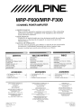
MRP-F600/M RP-F300
4 CHANNEL POWER AMPLIFIER
• OWNER'S MANUAL
Please read this manual to maximize your enjoyment of the outstanding
performance and feature capabilities of the equipment, then retain the
manual for future reference.
• MODE D'EMPLOr
Veuillez lire ce mode d'emploi pour tirer pleinement profit des excellentes
performances et fonctions de cet appareil, et conservez-le pour toute
reference future.
• MANUAL DE OPERACrON
Lea este manual, por favor, para disfrutar al maximo de las excepcionales
prestaciones y posibilidades funcionales que ofrece el equipo, luego
guarde el manual para usarlo como referencia en el futuro.
-
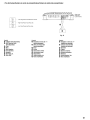
CONTENTS
WARNING
CAUTION
INSTALLATION.
ATTACHING THE TERMINAL COVERS
CONNECTIONS
CONNECTION CHECK LIST
SWITCH SETTINGS.
SYSTEM DIAGRAMS ...
SPECIFICATIONS. .
Self-Tapping Screw (M4 x 20).
Terminal Cover .
Screw (M3 x 12)
.
Speaker Input Connector
ALPINE ELECTRONICS MARKETING, INC.
1-1-8 Nishi Gotanda,
Shinagawa-ku,
Tokyo 141-0031. Japan
Phone 03-5496-8231
ALPINE ELECTRONICS OF AMERICA, INC.
19145 Gramercy Place, Torrance,
California 90501, U.S.A.
Phone 1-800-ALPINE-1 (1-800-257-4631)
ALPINE ELECTRONICS OF CANADA, INC.
777 Supertest Road, Toranto,
Ontario M3J 2M9, Canada
Phone 1-800-ALPINE-l (1-800-257-4631)
Espaitol
TABLE DES MATIERES
.... 2
. 3
4
5
.. 6
... 10
. 11
. 12
. 16
AVERTISSEMENT .
. 2
ATTENTION ....
. 3
INSTALLATION
.. 4
FIXATION DES CACHE-BORNES .....
.... 5
CONNEXIONS ..
... 6
L1STE DE VERIFICATION DES CONNEXIONS ... 10
REGLAGES DE COMMUTATEUR .
.11
DIAGRAMMES DU SYSTEME .
12
SPECIFICATIONS.
.
16
........ 4
.1 SET
•
•
•
•
ACCESSORIES
•
•
•
•
Fran ais
INDICE
ADVERTENCIA.
.
PRUDENCIA
.
INSTALACION
.
FIJACION DE LAS TAPAS DEL TERMINAL.
CONEXI ONES
L1STA DE COMPROBACION DE CONEXI ONES
AJUSTES DEL INTERRUPTOR
DIAGRAMAS DEL SISTEMA.
.
ESPECIFICACIONES
ACCESSOIRES
..4
. .
1
Vis autotaraudeuse (M4 x 20)
Cache-bornes
Vis (M3 x 12)
Connecteur d'entree de haut-parleur
ACCESORIOS
4
1 JEU
4
1
•
•
•
•
Tornillo autorroscante (M4 x 20)
Tapa del terminal. .
.
Tornillo (M3 x 12)
Conector de entrada del altavoz
... 4
1 JUEGO
.
4
.
1
ALPINE ELECTRONICS OF AUSTRALIA PTY. LTD.
161-165 Princes Highway, Hallam
Victoria 3803, Australia
Phone 03-8787-1200
ALPINE ITALIA S.p.A,
Viale C. Colombo 8, 20090 Trezzano
Sui Naviglio (MI), Italy
Phone 02-484781
ALPINE ELECTRONICS GmbH
Frankfurter Ring 117, 80807 Munchen, Germany
Phone 089-32 42 640
ALPINE ELECTRONICS DE ESPANA, SA
Portal de Gamarra 36, Pabell6n, 32
01013 Vitoria (Alava)-APDO 133, Spain
Phone 945-283588
ALPINE ELECTRONICS OF U.K. LTD.
Alpine House
Flefchamstead Highway, Coventry CV4 9TW, U.K.
Phone 0870-33 33 763
ALPINE ELECTRONICS FRANCE S.A.R.L.
(RCS PONTOISE B 338 101 280)
98, Rue de la Belle Efoile, Z.1. Paris Nord II.
B.P. 50016, 95945 Roissy Charles de Gaulle
2
3
4
..5
6
10
11
12
16
ALPINE ELECTRONICS (BENELUX) GmbH
Leuvensesteenweg 510-86.
1930 Zaventem, Belgium
Phone 02-725-1315
Cedex, France
Phone 01-48638989
QingDao DongLi X,nHaiYuan
Printing Co., ltd
No.17, JiuShuiDong Road
QingOao, China
Designed by ALPINE Japan
Printed in China
68-10872Z24-A
M3514325010
Fran ais
English
Espaftol
Introduction:
Introduction:
Introduccion:
Please read this OWNER'S MANUAL thoroughly to
familiarize yourself with each control and function. We
at ALPINE hope that your new MRP-F600/MRP-F300
will give you many years of listening enjoyment.
In case of problems when installing your MRP-F6001
MRP-F300, please contact your authorized ALPINE
dealer.
CAUTION: These controls are for tuning your system.
Please consult your authorized Dealer for adjustment.
Priilre de lire attentivement ce MODE D'EMPLOI pour
se familiariser avec chaque commande et fonction. Chez
Alpine, no us esperons que Ie nouveau MRP-F6001
MRP-F300 donnera de nombreuses annees de plaisir
d'ecoute.
En cas de problemes lors de I'installation du MRP-F6001
MRP-F300, priere de contacter Ie revendeur agree d'ALPINE.
PRECAUTION: Ces commandes sont utilisees pour
la syntonisalion du sysllime. Priere de contacter Ie
revendeur agree pour Ie reglage.
A fin de familiarizarse con los controles y funciones
de la unidad, lea detenidamente este MANUAL DE
OPERACION. Nosotros en ALPINE esperamos que su
nuevo MRP-F600/MRP-F300 Ie brinde muchos alios
de placer auditivo.
En caso de presentarse algun problema durante la instalacion del MRP-F600/MRP-F300, tome contacto con su
distribuidor autorizado ALPINE.
PRECAUCION: Estos controles sirven para la sintonizaci6n de su sistema. Contacte por favor a su distribuidor autorizado para el ajuste.
6
6
This symbol means important instructions.
WARNING Failure to heed them can result in
serious injury or death.
This symbol means important instructions.
CAUTION Failure to heed them can result in
injury or property damages
6
6
Ce symbole designe des instructions importantes. Le
AVERTISSEMENT non-respect de ces instructions peut entrainer de graves
blessures, voire la mort.
Ce symbole designe des instructions importantes. Le
non-respect de ces instrucATTENTION
tions peut entrainer des blessures ou des dommages materiels.
6
6
Este simbolo indica que las instrucciones son importantes. De
ADVERTENCIA no tenerse en cuenta pod ria
ocasionarse heridas graves 0
muerte.
Este simbolo indica que las instrucciones son importantes. De
PRUDENCIA no tenerse en cuenta pod ria
ocasionarse heridas graves 0
dalios materiales.
.& WARNING
.& AVERTISSEMENT
.& ADVERTENCIA
DO NOT OPERATE ANY FUNCTION THAT TAKES YOUR
ATTENTION AWAY FROM SAFELY DRIVING YOUR
VEHICLE. Any function that requires your prolonged
attention should only be performed after coming to a
complete stop. Always stop the vehicle in a safe location before performing these functions. Failure to do
so may result in an accident.
N'ACTIVER AUCUNE FONCTION SUSCEPTIBLE DE
DETOURNER VOTRE ATTENTION DE LA CONDUITE
DU VEHICULE. Les fonctions requerant une attention
prolongee ne doivent etre exploitees qu'a I'arret complet du vehicule. Toujours arreter Ie vehicule a un endroit sur avant d'activer ces fonctions. II y a risque de
provoq uer un accident.
NO REALICE NINGUNA OPERACION QUE PUEDA DlSTRAER SU ATENCION Y COMPROMETER LA SEGURIDAD DURANTE LA CONDUCCION DEL VEHicULO.
Las operaciones que requieren su atencion durante
mas tiempo solo deben realizarse despues de detener
completamente el vehiculo. Estacione el vehiculo en
un lugar seguro antes de realizar dichas operaciones.
De 10 contrario, pod ria ocasionar un accidente.
GARDER LE VOLUME AFAIBLE NIVEAU DE MANIERE
ENTENDRE LES BRUITS EXTERIEURS
PENDANT LA CONDUITE. Des niveaux de volume excessifs qui couvrent les sirenes des ambulances ou
les signaux routiers (passages a niveau, etc.) peuvent
etre dangereux et provoquer un accident. UN NIVEAU
DE VOLUME TROP ELEVE AL'INTERIEUR DU VEHICULE PEUT EGALEMENT AVOIR DES EFFETS IRREVERSIBLES SUR VOTRE AUDITION.
MANTENGA EL VOLUMEN AUN NIVEL QUE NO LE IMPIDA ESCUCHAR LOS SONIDOS DEL EXTERIOR MIENTRAS
CONDUCE. Los niveles de volumen demasiado altos que
reducen la percepcion de otros sonidos como las sirenas
de emergencia 0 posibles seliales acusticas de advertencia
en carretera (cruces de trenes, etc.) podrian ser peligrosos
y provocar un accidente. LOS NIVELES DE VOLUMEN ALTOS EN EL VEHicULO TAMBIEN PUEDEN DANAR EL SISTEMA AUDITIVO DE LOS PASAJEROS.
DO NOT DISASSEMBLE OR ALTER. Doing so may result in an accident, fire or electric shock.
NE PAS DESASSEMBLER NI MODIFIER L'APPAREIL.
II y a risque d'accident, d'incendie ou de choc electrique.
NO DESMONTE NI ALTERE LA UNlOAD. Si 10 hace.
podra ocasionar un accidente, un incendio 0 una descarga electrica.
USE THIS PRODUCT FOR MOBILE 12V APPLICATIONS. Use for other than its designed application may
result in fire, electric shock or other injury.
UTILISER CET APPAREIL POUR DES APPLICATIONS
MOBILES DE 12 V. Toute utilisation autre que I'application designee com porte un risque d'incendie, de
choc electrique ou de blessure.
UTILICE ESTE PRODUCTO CON APLICACIONES MOVILES DE 12 V. Si se emplea para otra aplicacion distinta de la prevista, podria producirse un incendio, una
descarga electrica u otras lesiones.
USE THE CORRECT AMPERE RATING WHEN REPLACING FUSES. Failure to do so may result in fire or electric shock.
UTlLlSER DES FUSIBLES DE L'AMPERAGE APPROPRIE. II y a risque d'incendie ou de decharge electrique.
UTI LICE EL AMPERAJE CORRECTO CUANDO CAMBIE FUSIBLES. De 10 contrario, puede producirse un
incendio 0 una descarga electrica.
DO NOT BLOCK VENTS OR RADIATOR PANELS. Doing so may cause heat to build up inside and may result in fire.
NE PAS OBSTRUER LES SORTIES D'AIR NI LES PANNEAUX DU RADIATEUR. Une surchauffe interne
peut se produire et provoquer un incendie.
NO OBSTRUYA LOS ORIFICIOS DE VENTILACION 0
LOS PANELES DEL RADIADOR. Si los bloquea, el calor podria acumularse en el interior y producir un incendio.
MAKETHE CORRECT CONNECTIONS. Failure to make
the proper connections may result in fire or
product damage.
EFFECTUER CORRECTEMENT LES CONNEXIONS. II
Ya risque de blessures ou de dommages a I'apparei!.
REALICE LAS CONEXIONES CORRECTAMENTE. Una
conexion incorrecta puede producir un incendio 0 daliar el equipo.
USE ONLY IN CARS WITH A 12 VOLT NEGATIVE
GROUND. (Check with your dealer if you are not sure.)
Failure to do so may result in fire, etc.
A UTILISER UNIQUEMENT SUR DES VOITURES A
MASSE NEGATIVE DE 12 VOLTS. (Verifiez aupres de
votre concessionnaire si vous n'en etes pas certain.)
II y a risque d'incendie, etc.
UTILICE LA UNlOAD SOLAMENTE EN VEHicULOS
QUE TENGAN 12 VOLTIOS CON NEGATIVO AMASA.
(Consulte a su distribuidor en caso de duda.) De no
ser as!, podria ocasionar un incendio, etc.
BEFORE WIRING, OISCONNECT THE CABLE FROM
THE NEGATIVE BATTERY TERMINAL. Failure to do so
may result in electric shock or injury due to electrical
shorts.
AVANTTOUTE CONNEXION, DEB RANCHER LE CABLE
DE LA BORNE NEGATIVE DE LA BATTERIE. II y a risque de choc electrique ou de blessure par courts-circuits.
ANTES DE EFECTUAR EL CABLEADO, DESCONECTE
EL CABLE DEL TERMINAL NEGATIVO DE LA BATERiA. De no hacerlo asi, podria ocasionar una descarga electrica 0 heridas debido a cortocircuitos electricos.
KEEP THE VOLUME AT A LEVEL WHERE YOU CAN
STILL HEAR OUTSIOE NOISES WHILE DRIVING. Excessive volume levels that obscure sounds such as
emergency vehicle sirens or road warning signals (train
crossings, etc.) can be dangerous and may result in
an accident. LISTENING AT LOUD VOLUME LEVELS
IN A CAR MAY ALSO CAUSE HEARING DAMAGE.
2
APOUVOIR
Fran ais
EngliBD
ESpanDI
DO NOT ALLOW CABLES TO BECOME ENTANGLED
IN SURROUNDING OBJECTS. Arrange wiring and
cables in compliance with the manual to prevent obstructions when driving. Cables or wiring that obstruct
or hang up on places such as the steering wheel, gear
lever, brake pedals, etc. can be extremely hazardous.
NE PAS COINCER LES CABLES AVEC DES OBJETS
VOISINS. Positionner les cables conformement au
manuel de maniere aeviter toute obstruction en cours
de conduite. Les cables qui obstruent ou depassent a
des endroits tels que Ie volant, Ie levier de changement de vitesses, la pedale de frein, etc., peuvent s'averer extremement dangereux.
IMPIOA QUE LOS CABLES SE ENREDEN CON LOS OBJETOS SITUADOS ALREDEDOR. Disponga la instalacion
electrica y los cables conforme a 10 descrito en el manual para evitar obstaculos durante la conduccion. Los
cables que obstaculizan la conduccion 0 que cuelgan de
partes del vehiculo como el volante de direcci6n, la palanca de cambios, los pedales de freno, etc., se consideran extremadamente peligrosos.
DO NOT SPLICE INTO ELECTRICAL CABLES. Never
cut away cable insulation to supply power to other
equipment. Doing so will exceed the current carrying
capacity of the wire and result in fire or electric shock.
NE PAS DENUDER LES CABLES ELECTRIQUES. Ne
jamais enlever la gaine isolante pour alimenter un autre
appareil. II y a risque de depassement de la capacite
de courant et, partant, d'incendie ou de choc electrique.
NO EMPALME CABLES ELECTRICOS. Nunca corte el
aislamiento de un cable para suministrar energia aotro
equipo. Esto hace que la capacidad portadora del cable se supere y puede ser la causa de incendios 0 descargas electricas.
DO NOT DAMAGE PIPE OR WIRING WHEN DRILLING
HOLES. When drilling holes in the chassis for installation, take precautions so as not to contact, damage
or obstruct pipes, fuel lines, tanks or electrical wiring.
Failure to take such precautions may result in fire.
NE PAS ENDOMMAGER DE CONDUITES NI DE cABLES LORS DU FORAGE DES TROUS. Lors du forage de
trous dans Ie chassis en vue de I'installation, veiller ane
pas entrer en contact, endommager ni obstruer de conduites, de tuyaux a carburant ou de fils electriques. Le
non-respect de cette precaution peut entrainer un incendie.
EVITE DANAR LOS TUBOS YEL CABLEADO CUANDO
TALADRE AGUJEROS. Si taladra agujeros en el chasis durante la instalacion, tome las precauciones necesarias para no rozar, danar u obstruir los tubos, las
tUberias de combustible, los depositos 0 el cableado
electrico. De 10 contrario, pod ria provocar un incendio.
DO NOT USE BOLTS OR NUTS IN THE BRAKE OR
STEERING SYSTEMS TO MAKE GROUND CONNECTIONS. Bolts or nuts used for the brake or steering
systems (or any other safety-related system), or tanks
should NEVER be used for installations or ground connections. Using such parts could disable control of
the vehicle and cause fire etc.
NE PAS UTiLISER DES ECROUS NI DES BOULONS
DU CIRCUIT DE FREINAGE OU DE DIRECTION POUR
LES CONNEXIONS DE MASSE. Les boulons et les
ecrous utilises pour les circuits de freinage et de direction (ou de tout autre systeme de securite) ou les
reservoirs ne peuvent JAMAIS etre utilises pour I'installation ou la liaison a la masse. L'utilisation de ces
organes peut desactiver Ie systeme de controle du
vehicule et causer un incendie, etc.
NO UTILICE TUERCAS 0 PERNOS EN EL SISTEMA
DE FRENOS 0 DE DlRECCION PARA REALIZAR LAS
CONEXIONES AMASA. Los pernos 0 tuercas empleados en los sistemas de freno 0 de direccion (0 en cualquier otro sistema relacionado con la seguridad del
vehiculo), 0 los depositos, NUNCA deben utilizarse
para instalaciones de cableado 0 conexion amasa. Si
utiliza tales partes podra incapacitar el control del vehiculo y provocar un incendio, etc.
KEEP SMALL OBJECTS SUCH AS BATTERIES OUT OF
THE REACH OF CHILDREN. Swallowing them may
result in serious injury. If swallowed, consult a physician immediately.
GARDER LES PETITS OBJETS COMME LES PILES
HORS DE PORTEE DES ENFANTS. L'ingestion de tels
objets peut entrainer de graves blessures. En cas d'ingestion, consulter immediatement un medecin.
MANTENGA LOS OBJETOS PEQUENOS, COMO LAS PI·
LAS, FUERA DEL ALCANCE DE LOS NINOS. La ingestion
de estos objetos puede provocar lesiones graves. Si esto
ocurre, con suite con un medico inmediatamente.
&
CAUTION
&
ATTENTION
&
PRUDENCIA
HALT USE IMMEDIATELY IF A PROBLEM APPEARS.
Failure to do so may cause personal injury or damage
to the product. Return it to your authorized Alpine
dealer or the nearest Alpine Service Center for repairing.
INTERROMPRE TOUTE UTILISATION EN CAS DE PROBLEME. Le non-respect de cette precaution peut entrainer des blessures ou endommager I'appareil. Retourner I'appareil aupres du distributeur Alpine agree
ou un centre de service apres-vente Alpine en vue de
la reparation.
DEJE DE USAR LA UNlOAD INMEDIATAMENTE SI
APARECE ALGUN PROBLEMA. Su uso en estas condiciones podria ocasionar lesiones personales 0 danos al producto. L1eve la unidad aun distribuidor Alpine
autorizado 0 al Centro de servicio Alpine mas proximo para repararla.
HAVE THE WIRING AND INSTALLATION DONE BY
EXPERTS. The wiring and installation of this unit requires special technical skill and experience. To ensure safety, always contact the dealer where you purchased this product to have the work done.
FAIRE INSTALLER LE CABLAGE ET L'APPAREIL PAR
DES EXPERTS. Le cablage et I'installation de cet appareil requiert des competences techniques et de I'experience. Pour garantir la securite, faire proceder a
I'installation de cet appareil par Ie distributeur qui vous
I'a vendu.
CON FiE EL CABLEADO YLA INSTALACION APROFESIONALES. EI cableado y la instalaci6n de este equipo requieren una competencia y experiencia tecnica
confirmada. Para garantizar la seguridad, pongase
siempre en contacto con el distribuidor al que ha comprado el equipo para confiarle estas tareas.
USE SPECIFIED ACCESSORY PARTS AND INSTALL
THEM SECURELY. Be sure to use only the specified
accessory parts. Use of other than designated parts
may damage this unit internally or may not securely
install the unit in place. This may cause parts to become loose resulting in hazards or product failure.
UTILISER LES ACCESSOIRES SPECIFIES ET LES INSTALLER CORRECTEMENT. Utiliser uniquement les accessoires specifies. Lutilisation d'autres composants que les composants specifies peut causer des dommages internes a
cet appareil ou son installation risque de ne pas etre effectuee correctement. Les pieces utilisees risquent de se desserrer et de provoquer des dommages ou une detaillance
de I'appareil.
UTI LICE LOS ACCESORIOS ESPECIFICADOS E INSTALELOS CORRECTAMENTE. Asegurese de utilizar los
accesorios especificados solamente. La utilizacion de
otras piezas no designadas puede ser la causa de danos en el interior de la unidad 0 de una instalacion
incorrecta. Las piezas pueden aflojarse, 10 que, ademas de ser peligroso, puede provocar averfas.
ARRANGE THE WIRING SO IT IS NOT CRIMPED OR
PINCHED BY ASHARP METAL EDGE. Route the cables
and wiring away from moving parts (like the seat rails)
or sharp or pointed edges. This will prevent crimping
and damage to the wiring. If wiring passes through a
hole in metal, use a rubber grommet to prevent the
wire's insulation from being cut by the metal edge of
the hole.
FAIRE CHEMINER LE CABLAGE DE MANIERE ANE
PAS LE COINCER CONTRE UNE ARETE METALLIQUE.
Faire cheminer les cables aI'ecart des pieces mobiles
(com me les rails d'un siege) et des aretes acerees ou
pointues. Cela evitera ainsi de coincer et d'endommager les cables. Si un cable passe dans un orifice metallique, utiliser un passe-cloison en caoutchouc pour
eviter que la gaine isolante du cable ne soit end ommagee par Ie rebord metallique de I'orifice.
DlSPONGA EL CABLEADO DE FORMA QUE LOS CABLES NO SE DOBLEN, NO SE CONTRAIGAN NI ROCEN UN BORDE METALICO AFILADO. Aleje los cables y el cableado de piezas moviles (como los railes
de los asientos) 0 de bordes puntiagudos 0 afilados.
De esta forma evitara dobleces y danos en el cableado.
Si los cables se introducen por un orificio de metal,
utilice una arandela de goma para evitar que el borde
metalico del orificio corte el aislamiento del cable.
DO NOT INSTALL IN LOCATIONS WITH HIGH MOISTURE OR DUST. Avoid installing the unit in locations
with high incidence of moisture or dust. Moisture or
dust that penetrates into this unit may result in product failure.
NE PAS INSTALLER ADES ENDROITS TRES HUMIDES OU POUSSIEREUX. Eviter d'installer I'appareil a
des endroits soumis a une forte humidite ou a de la
poussiere en exces. La penetration d'humidite ou de
poussiere aI'interieur de cet appareil risque de provoquer une defaillance.
NO INSTALE LA UNlOAD EN LUGARES MUY HUMEDOS 0 LLENOS DE POLVO. Evite instalar la unidad en
lugares con altos indices de humedad 0 polvo. Si entra polvo 0 humedad, el equipo puede averiarse.
3
Fran ais
English
Espanal
INSTALLATION
INSTALLATION
INSTALACION
Due to the high power output of the MRP-F600/MRPF300, considerable heat is produced when the amplifier is in operation. Forthis reason, the amplifier should
be mounted in a location which will allow for free circulation of air, such as inside the trunk. For alternate
installation locations, please contact your authorized
Alpine dealer.
En raison de la sortie de puissance elevee du MRPF600/MRP-F300, une forte chaleur est produite pendant Ie fonctionnement de I'amplificateur. Pour cette
raison, I'amplificateur doit etre monte dans un endroit
permettant une bonne ventilation, tel que Ie coffre. Pour
ce qui concerne les differentes positions d'installation,
contacter un concessionnaire Alpine.
Debido ala salida de alta potencia del MR P-F600/MRPF300, se produce un calor considerable cuando el
amplificador esta en funcionamiento. Por esta razon,
el amplificador debera montarse en una ubicacion que
permita la libre circulacion de aire, como por ejemplo
dentro del maletero. Para ubicaciones de instalacion
alternativas, por favor contacte a su distribuidor de
Alpine autorizado.
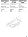
1. Using the amplifier as a template, mark the four
screw locations.
2. Make sure there are no objects behind the surface
that may become damaged during drilling.
3. Drill the screw holes.
4. Position the MRP-F600/MRP-F300 over the screw
holes, and secure with four self-tapping screws.
1. Apposer I'amplificateur contre la surface d'installation pour marquer les reperes des quatre vis.
2. Verifier qu'il n'y a pas d'objets derriere la surface
pouvant etre abimes lorsque les trous soient perces.
3. Percer les trous pour les vis.
4. Positionner Ie MRP-F600/MRP-F300 par dessus les
trous et fixer avec les quatre vis auto-taraudees.
1. Utilizando el amplificador como plantilla, marque
la ubicacion de los cuatro tornillos.
2. Asegurese de que no hay objeto alguno bajo la superficie que pueda verse dafiado durante la perforacion de los agujeros.
3. Perfore los agujeros para los tornillos.
4. Situe el MRP-F600/MRP-F300 sobre dichos agujeros, y asegurelo con cuatro tornillos autorroscantes.
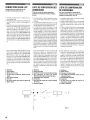
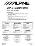
NOTE:
To securely connect the ground lead, use an already
installed screw on the metal part of the vehicle (marked
(*), sold separately). Be sure this is a good ground
by checking continuity to the battery (-) terminal. As
much as possible connect all equipment to the same
ground point. These procedures will help eliminate
noise.
REMARQUE:
Pour connecter solidement Ie conducteur de mise a la
terre, utiliser la vis deja fixee sur la partie metallique du
vehicule (signalee (*), vendu separement). Assurezvous que ce point est une bonne mise ala terre en verifiantla continuite a la borne de la batterie (-). Si possible, connecter tout I'equipement au meme point de mise
a la terre. Geci vous aidera a eliminer Ie bruit.
NOTA:
Para conectar de forma segura el cable de tierra, utilice un
tornillo ya instalado en la parle metaliea del vehiculo (mareado (*), vendido separadamente). Asegurese de que es
un punto de tierra bueno verifieando la continuidad con el
terminal de la bateria (-). Gonecte siempre que sea posible
todo el equipo en el mismo punto de tierra. Esto ayudara a
eliminar el ruido.
G)
@
@
@
Self-Tapping Screws (M4 x 20)
Ground Lead
Chassis
Holes
G)
@
@
@
Vis auto-taraudees (M4 x 20)
Conducteur de mise ala terre
Chassis
Trous
@~----4
G)
@
@
@
Tornillos autorroscantes (M4 x 20)
Cable de tierra
Chasis
Agujeros
Fig. 1
ATTACHING THE TERMINAL
COVERS
FIXATION DES
CACHE-BORNES
FIJACI()N DE LAS TAPAS DEL
TERMINAL
Attach the terminal covers (supplied) after connections
and confirmation of correct operation.
Attaching the terminal covers will improve the appearance of the unit.
Fixez les cache-bornes (fournis) apres avoir verifie que
les raccordements ont ete correctement effectues et
que I'appareil fonctionne correctement.
La fixation des cache-bornes ameliore I'aspect de I'appareil.
Fije las tapas del terminal (suministradas) tras realizar
las conexiones y confirmar que la unidad funciona
correctamente.
La fijaci6n de las tapas del terminal mejorara la
apariencia de la unidad.
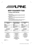
How to attach the terminal covers:
Attach the left and right terminal covers using the supplied screws (M3 x 12), as shown in the figure below.
Comment fixer les cache-bornes:
Fixez les cache-bornes gauche et droit it I'aide des vis
(M3 x 12) fournies, comme indique dans Ie schema cidessous.
Como fiiar las tapas del terminal:
Fije las tapas izquierda y derecha del terminal con los
tornillos (M3 x 12) suministrados, tal como se indica
en la siguiente figura.
CD Right terminal cover
@ Left terminal cover
@ Screw (M3 x 12)
CD Cache-bornes droit
@ Cache-bornes gauche
@ Vis (M3 x 12)
CD Tapa derecha del terminal
@ Tapa izquierda del terminal
@ Tornillo (M3 x 12)
NOTE:
Do not lift or carry the unit by the attached terminal
covers.
REMARQUE:
Ne transportez pas et ne soulevez pas I'unite par les
cache-bornes.
NOTA:
No eleve ni transporte la unidad cogiendola de las tapas
del terminal.
5
English
Fran ais
Espanol
o
MRp·F600
(Left Side/Cote
Lado izquierdo)
gauc~~ -Or --
L::::;:~ :
(Right Side/
Cote droiV
Lado derecho)
0
fj
onbJ
49
~
~
~~~~0
4D
4e
C8
II
4D
CD
o
MRp·F300
---T--(Left Side/Cole gauche/
Lado izquierdo)
0
8
o
o
(Right Side/
Cote droiV
Lado derecho)
0
fj ===~0
tr,>
'Q:I'
~
4D
4e
C8
4D ===="
CD ~~~~=!J
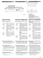
CONNECTIONS
Fig. 3
CONNEXIONS
CONEXIONES
Before making connections, be sure to turn the power
off to all audio components. Connect the yellow battery lead from the amp directly to the positive (+) terminal of the vehicle's battery. Do not connect this lead
to the fuse block.
Avant d'effectuer les connexions, verifier que tous les
composants audio sont hors tension. Connectez Ie
conducteur jaune de la baUerie provenant de
I'amplificateur directement a la borne positive (+) de
la batterie du vehicule. Ne pas Ie connecter au bottier
de fusibles.
Antes de efectuar las conexiones, asegurese de que
apaga todos los componentes audio. Conecte el cable
amarillo de la bateria proveniente del amplificador
directamente al terminal positivo (+) de la bateria del
vehiculo. No conecte dicho cable al bloque de fusibles.
To prevent external noise from entering the audio
system.
Locate the unit and route the leads at least 10 cm
(3-15/16") away from the car harness.
Keep the battery power leads as far away from other
leads as possible.
Connect the ground lead securely to a bare metal
spot (remove any paint or grease if necessary) of
the car chassis.
If you add an optional noise suppressor, connect it
as far away from the unit as possible. You r Alpine
dealer carries various noise suppressors, contact
them for further information.
Your Alpine dealer knows best about noise prevention measures so consult your dealer for further
information.
Pour eviter que des bruits exterieurs interlinent
avec Ie systeme audio.
• Installez I'appareil et acheminez les cables a au
moins 10 cm (3-15/16") de distance du faisceau de
cables de la voiture.
• Eloignez les cables d'alimentation de la batterie Ie
plus possible des autres cables.
• Raccordez bien Ie fil de terre a un point metallique
apparent (enlevez la couche de peinture ou de
graisse si necessaire) du chassis de la voiture.
• Si vous rajoutez un filtre antiparasites en option,
raccordez-Ie Ie plus loin possible de I'appareil.
Contactez votre revendeur Alpine pour plus de
details sur les divers filtres antiparasites disponibles.
• Consultez votre revendeur Alpine pour plus de
details sur les mesures de prevention contre les
parasites.
Para evilar que entre ruido externo en el sistema
de audio.
• Coloque la unidad y pase los cables a 10 cm (3-15/
16") por 10 menos del conjunto de cables del
automovil.
• Mantenga los conductores de alimentacion de la
bateria 10 mas alejados posible de otros cables.
• Conecte el conductor de puesta a tierra con
seguridad a un punto metalico desnudo (si es
necesario, eli mine Ie pintura 0 la grasa) del chasis
del automovil.
• Si afiade un supresor de ruido opcional, conectelo
10 mas lejos posible de la unidad. Su proveedor Alpine dispone de varios supresores de ruido.
Solicitele mas informacion.
• Su proveedor Alpine conoce la mejor forma de evitar
el ruido. Solicitele mas informacion.
6
o Speaker Output Terminals
o Bornes de sortie de haut-parleur
o Terminales de salida del altavoz
The MRP-F600/MRP-F300 has two sets of speaker
outputs. Be sure to observe correct speaker output connections and phasing in relation to the other
speakers in the system. Connect the positive output to the positive speaker terminal and the negative to negative. Do not connect the speaker (-)
terminal to the vehicle's chassis.
Le MRP-F600/MRP-F300 possede deux jeux de
bornes de sortie du haut-parleur. Veillez aeffectuer
correctement les raccordements aux bornes de
sortie correspondantes par rapport aux autres hautparleurs du systeme. Raccordez la borne de sortie
positive a la borne positive du haut-parleur, et la
borne negative a la borne negative. Ne raccordez
pas la borne negative du haut-parleur (-) au chassis
du vehicule.
EI MRP-F600/MRP-F300 tiene dos juegos de salida
de altavoz. Asegurese de observar las conexiones
correctas de salida del altavoz y la puesta en fase
en relaci6n con los otros altavoces del sistema.
Conecte la salida positiva al terminal del altavoz
positivo y la negativa al negativo. No conecte el
terminal del altavoz (-) al chasis del vehiculo.
In the bridged mode, connect the left positive to
the positive terminal on the speaker and the right
negative to the negative terminal of the speaker.
Do not use the speaker (-) terminals as a common lead between the left and right channels. Do
not connect this lead to the vehicle's chassis.
En mode ponte, connecter la sortie positive gauche
sur la borne positive du haut-parleur et la sortie
negative droite sur la borne negative du hautparleur. Ne pas utiliser les bornes haut-parleur (-)
a la fois pour les canaux droit et gauche. Ne pas
connecter ce cable sur Ie chassis du vehicule.
En el modo de puente, conecte la salida izquierda
positiva al terminal positivo del altavoz y la salida
derecha negativa al terminal negativo del altavoz.
No utilice los terminales de altavoz (-)
conjuntamente entre los canales derecho e
izquierdo, ni los conecte al chasis del vehfculo.
NOTES:
1. Do not connect speaker leads together or to
chassis ground.
2. Use a V-adaptor (sold separately) for the input
when bridging the outputs. (Refer to the "Bridge
Connections" on page 13)
REMARQUES:
1. Jamais connecter les conducteurs de hautparleur
ensemble ou sur la terre du chassis.
2. Pour I'entree, utiliser un adaptateur en forme de
Y (vendu separement) en cas de connexion en
pont des sorties. (Se reporter a« Connexions
pontees ", page 13)
NOTAS:
1. Nunca conecte los cables de altavoz juntos 0 en
el punto de tierra del chasis.
2. En caso de conexi6n derivada de las salidas, use
un adaptador Y (se vende por separado) para la
entrada. (Consulte la secci6n "Conexiones
derivadas", pagina 13)
e Power Supply Terminal
e Ground Lead (Sold Separately)
Connect this lead securely to a clean, bare metal
spot on the vehicle's chassis. Verify this point to
be a true ground by checking for continuity between that point and the negative (-) terminal of
the vehicle's battery. Ground all your audio components to the same point on the chassis to prevent ground loops.
Only use * * AWG4 (the wire gauge) for this connection.
**MRP-F600
AWG4
MRP-F300
AWG8
o Remote Turn-On Lead (Sold Separately)
Connect this lead to the remote turn-on or power
antenna (positive trigger, (+) 12V only) lead of your
head unit.
o Battery Lead (Sold Separately)
Be sure to add a * 75 amp fuse as close as possible to the battery's positive (+) terminal. This fuse
will protect your vehicle's electrical system in case
of a short circuit. If you need to extend this lead,
only use * * AWG4 (the wire gauge) for this connection.
*MRP-F600..
.75 amp fuse
MRP-F300
50 amp fuse
* MRP-F600
AWG4
MRP-F300
AWG8
*
e Borne d'alimentation electrique
e Terminal de suministro de energia
e Conducteur de mise ala terre (vendu separement) e Cable de tierra (vendido separadamente)
Connecter ce conducteur sur un endroit propre et
metallique du chassis du vehicule. Verifier la mise
a la terre en contr61ant Ie passage de courant
continu entre ce point et la borne negative (-) de
la batterie du vehicule. Mettre a la terre tous les
composants audio au meme point sur Ie chassis
pour eviter des boucles de terre.
N'utilisez que des cables de type
AWG4
(epaisseur du cable) pour effectuer cette
connexion.
**MRP-F600
AWG4
MRP-F300
AWG8
**
Conecte este cable con seguridad en un punta
metalico expuesto, limpio, en el chasis del vehfculo.
Verifique que este punta es un verdadero punta de
puesta atierra comprobando si existe continuidad
entre este punto y el terminal negativo (-) de la
baterfa del vehfculo. Conecte atierra todos sus
componentes audio en el mismo punta del chasis
para prevenir bucles en la conexi6n atierra.
Uti lice unicamente * AWG4 (los taman os del
cable) para realizar esta conexi6n.
**MRP-F600
AWG4
MRP-F300
AWG8
*
o Conducteur de mise sous tension telecom- o Cable para encendido remoto (vendido
mandee (vendu separement)
Connecter ce conducteur au conducteur de mise
sous tension telecommandee ou au conducteur
d'antenne electrique (declencheur positif, (+) 12V
seulement) de votre unite principale.
o Conducteur de la batterie (vendu separement)
Assurez-vous d'ajouter un *fusible de 75A Ie plus
pres que possible de la borne positive (+) de la
batterie. Ce fusible protegera Ie systeme electrique
de votre vehicule au cas de court-circuit. Si ce
conducteur doit etre rallonge, n'utilisez que les
cables de type **AWG4 (epaisseur du cable)
pour effectuer cette connexion.
* MRP-F600
Fusible de 75A
MRP-F300
Fusible de 50A
MRP-F600
AWG4
MRP-F300
AWG8
**
separadamente)
Conecte este cable al cable de encendido remoto 0
de antena electrica (disparador positivo (+) de 12V
solamente) de su unidad principal.
o Cable de la bateria (vendido separadamente)
Asegurese de anadir un *fusible de 75A tan cerca
como sea posible del terminal positivo (+) de la
bateria. Este fusible protegera el sistema electrico
de su vehfculo en caso de que se produzca un
cortocircuito. Si necesita extender este cable, utilice
unicamente tamanos
AWG4 (los tamaiios del
cable) para realizar esta conexi6n.
MRP-F600
Fusible de 75A
MRP-F300
Fusible de 50A
MRP-F600
AWG4
MRP-F300
AWG8
**
*
**
7
English
Fran ais
o Prises de sortie de preamplificateur
o Pre-Out Jacks
Espana'
o Clavijas de salida de preamplificador
These jacks provide a Front + Rear summed output (Non-fading). This is an ideal output for driving a separate subwoofer amp. This output is fullrange, and is not affected by the crossover.
Ces prises assurent une sortie accumuhle Avant +
Arriere (sans attenuation). C'est une sortie ideale
pour entrainer un amplificateur de haut-parleur des
sous-graves separe. Cette sortie est pleine gam me,
et n'est pas affectee par Ie diviseur de frequences.
Estos conectores proporcionan una salida
delantera + trasera conjunta (sin desvanecedor).
Esta salida es ideal para excitar un amplificador de
altavoz de frecuencias ultrabajas separado. Esta
salida es de gama completa, y no es afectada por
el filtro separador.
f) RCA Input Jacks
Connect these jacks to the line out leads on your
head unit using RCA extension cables (sold separately). Be sure to observe correct channel connections; Left to Left and Right to Right.
(Front to Front and Rear to Rear)
f) Prises d'entrlle RCA
Connecter ces prises aux conducteurs de sortie
de ligne de I'unite principale en utilisant les cables
d'extension RCA (vendus separement). Verifier que
les connexions de canal sont correctes: gauche/
vers la gauche et droite/vers la droite.
(Avant vers I'avant et arriere vers I'arriere)
f) Clavijas RCA de entrada
Conecte las mismas a los cables de salida de linea
de su unidad principal utilizando cables de
extension RCA (vendidos por separado). Asegurese
de que respeta las conexi ones de canal correctas;
izquierda para izquierda y derecha para derecha.
(Delantera a delantera y trasera atrasera)
o Speaker Level Input Connector
o Connecteur d'entrlle de niveau de haut-parleur
o Conector de entrada de nivel del altavoz
These leads are input leads for use with head units
not equipped with preamp outputs. When not using the RCA Line Input connectors, you should
connect these wires to the speaker output leads of
your head unit. The MRP-F600/MRP-F300 accepts
input from high power or standard power head
units.
NOTE:
Use either RCA line level or speaker level inputs.
Do not connect both at the same time.
~
Speaker Input Leads
These leads are input leads for use with head units
not equipped with preamp outputs. Connect these
wires to the speaker output leads of your head unit.
The MRP-F600/MRP-F300 accepts input from high
power or standard power head units.
CID Front Left Speaker (White (+))
Son cables de entrada para uso con unidades
principales sin salidas de preamplificador. Si no
utiliza conectores de entrada de linea RCA, debeni
conectar estos cables a los cables de salida de
altavoz de la unidad principal. EI MRP-F600/MRPF300 ace pta entrada a partir de unidades
principales de alta potencia 0 de potencia normal.
Ces conducteurs sont des conducteurs d'entree
pour utilisation avec unites principales non
equipees de sorties de preamplificateur. Si vous
n'utilisez pas des connecteurs d'entree de ligne
RCA, vous devez connecter ces cables aux
conducteurs de sortie de hautparleur de I'unite
principale. Le MRP-F600/MRP-F300 accepte entree
a partir d'unites principales de haute puissance ou
de puissance normale.
NOTA:
Utilice las entradas de nivel de altavoz 0 de nivel
de linea RCA. No conecte las dos al mismo tiempo.
REMARQUE:
Utiliser les entrees de niveau de Iigne RCA ou de
niveau de haut-parleur. Jamais les connecter ala fois.
~
Conducteurs d'entree de haut-parleur
Ces conducteurs sont des conducteurs d'entree
pour utilisation avec unites principales non
equipees de sorties de preamplificateur. Connecter
ces cables aux conducteurs de sortie de hautparleur de I'unite principale. Le MRP-F600/MRPF300 accepte entree Ii partir d'unites principales
de haute puissance ou de puissance normale.
~
Cables de entrada del altavoz
Son cables de entrada para uso con unidades
principales sin salidas de preamplificador. Conecte
estos cables a los cables de salida de altavoz de la
unidad principal. EI MRP-F600/MRP-F300 acepta
entrada a partir de unidades principales de alta
potencia 0 de potencia normal.
CID Haut-parleur avant gauche (Blanc (+))
CID Altavoz delantero izquierdo (Blanco (+))
CD Haut-parleur avant gauche (Blanc/Noir (-))
CD Altavoz delantero Izquierdo (Blanco/Negro H)
'8 Haut-parleur avant droit (Gris (+))
'8 Altavoz delantero derecho (Gris (+))
G) Front Right Speaker (Gray/Black H)
G) Haut-parleur avant droit (Gris/Noir (-))
G) Altavoz delantero derecho (Gris/Negro H)
CD Rear Left Speaker (Green (+))
CD
CD Altavoz trasero Izquierdo (Verde (+))
C9 Rear Left Speaker (Green/Black H)
C9 Haut-parleur arriilre gauche (Vert/Noir (-))
C9 Altavoz trasero izquierdo (Verde/Negro H)
~
~
Haut-parleur arriere droit (Violet (+))
~
CD
Haut-parleur arriere droit (Violet/Noir (-))
CD Altavoz trasero derecho (Violeta/Negro H)
CD
Front Left Speaker (White/Black
'8
Front Right Speaker (Gray (+))
H)
Rear Right Speaker (Violet (+))
CD Rear Right Speaker (Violet/Black H)
8
Haut-parleur arriere gauche (Vert (+))
Altavoz trasero derecho (Violeta (+))
Fran ais
En #ish
Espanol
7 - 10 mm (9/32" - 3/8")
-r-
Lead end side of the product!
Coteextn3mite du conducteur du produit!
Extremo del conductor del producto
Fig. 4
ScrewNisfTornilio
Lead/Conducteur/Alambre
--I
~~ ~
).::r~adTerminal/Borne de conducteurfTerminal del conductor
Fig. 5
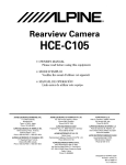
Cautions on wire lead connections
(MRP-F600 only)
When using third-party wire cables (power supply
wire), use the supplied screws to simplify the connection. Refer to the description below for the proper
procedure.
If you are in doubt about how to make this connection, consult your dealer.
Precautions avec les connexions des fils
conducleurs (MRP-F600 uniquement)
Lorsque vous utilisez des cables conducteurs d'autres
fabricants (cable d'alimentation), utilisez les vis
fournies pour simplifier la connexion.
Faire correctement les connexions en se referant a la
description suivante.
Si vous avez des doutes, contactez votre revendeur.
Precauciones durante la conexion de alambres
(solo MRP-F600)
Si utiliza cables de otros fabricantes (cable de fuente
de alimentaci6n), utilice los tornillos suministrados
para simplificar la conexi6n. Asegurese de efectuar
correctamente las conexiones siguiendo el
procedimiento que se describe a continuaci6n.
Si tiene dudas sabre la forma de hacer las conexiones,
consulte a su distribuidor.
1. Check the wire size.
1. Verifier Ie calibre des fils.
1. Compruebe el tamaiio de los alambres.
NOTES:
• Wire Size (Battery Lead, Ground Lead):
Recommended wire size for this unit is AWG4.
·If the wire gauge used is unknown, ask your dealer.
2. Remove the insulation from the ends of the wire
leads by about 7 - 10mm (9/32" - 318"). (Fig. 4)
NOTES:
• If length of the exposed wire is too short, a poor
connection may occur causing operation failure
or sound interruption.
• On the other hand, if the length is too long, an
electrical short-circuit may occur.
3. Turn the screw attached to the terminal. Insert the
exposed wire end into the lead terminal. Tighten
the screw (included), to fix the lead. (Fig. 5)
Before making this connection, use insulated
shrink tUbing to cover any exposed wire
extending beyond the terminal.
NOTES:
• Use only the screws included.
• For safety reasons, connect the battery leads last.
• To prevent disconnection of the leads or dropping
of the unit, do not use the cabling to carry the
unit.
REMAROUES:
• Calibre des fils (Conducteur de la batterie,
conducteur de mise a la terre):
Le calibre des fils recommandes pour I'appareil
est AWG4.
• Si Ie calibre des fils utilises est inconnu, se
renseigner aupres du revendeur.
2. Retirer I'isolation des bouts des fils de connexion
de 7 -10mm (9/32" - 318"). (Fig. 4)
REMAROUES:
• Si la longueur des conducteurs avec !'isolation
retiree est trop courte, une connexion incorrecte
risque de se produire et cela peut provoquer une
panne de fonctionnement au I'interruption du son.
• D'autre part, si la longueur du conducteur est trap
longue, un court-circuit electrique risque de se
produire.
3. Tourner la vis fixee a la borne. Inserer Ie bout du
conducteur expose dans la borne du conducteur.
Serrez la vis (fournie) pour fixer Ie conducteur.
(Fig. 5)
Avant de faire cette connexion, utiliser la gaine
nltrecissable isolante afin de couvrir les cables
denudes depassant la borne.
REMAROUES:
• Utiliser uniquement les vis fournies.
• Par mesure de securite, connecter les fils de la
batterie en dernier.
• Pour eviter Ie debranchement des conducteurs au
de faire tomber I'appareil, ne pas saisir les
conducteurs lars du transport de I'appareil.
NOTAS:
• Tamaiio de los alambres (Cable de la bateria, cable
de puesta a tierra):
EI tamaiio del alambre recomendado para esta
unidad es de AWG4.
• Si no conoce el tamaiio del alambre empleado,
consulte a su distribuidor.
2. Quite aproximadamente 7 - 10mm (9/32" - 3/8")de
aislaci6n de los extremos de los alambres. (Fig. 4)
NOTAS:
• Si ellargo de los conductores sin aislaci6n es
demasiado carta, las conexiones podre!n quedar
mal hechas, 10 que a su vez podra causar fallas
de operaci6n a interrupciones en el son ida.
• Par otro lado, si los conductores sin aislaci6n
son demasiado largos, podran producirse
cortocircuitos electricos.
3. Girar el tornillo fijado al terminal. Inserte el
extrema desnudo del alambre en el terminal del
conductor. Apriete el tornillo (incluido) para fijar
el cable. (Fig. 5)
Antes de hacer esta conexion, use un manguito
aislante conlraible para cubrir los cables
expuestos que sobresalen del terminal.
NOTAS:
• Use s610 los tornillos incluidos.
• Par razones de seguridad, conecte los cables de
a bateria al final.
• Para evitar la desconexi6n de los alambres a la
caida de la unidad, asegurese de no coger los
alambres para transportar la unidad.
9
English
CONNECTION CHECK LIST
Fran ais
EspaiJol
lISTE DE VERIFICATION DES
CONNEXIONS
lISTA DE COMPROBACU)N
DE CONEXIONES
Priere de verifier les points enumeres
ci-dessous concernant I'unite principale:
(Fig. 6)
Por favor compruebe el estado de su
unidad principal segun las condiciones
listadas a continuacion: (Fig. 6)
a. The head unit does not have a remote turn-on or
power antenna lead.
b. The head unit's power antenna lead is activated only
when the radio is on (turns off in the tape or CD
Mode)
c. The head unit's power antenna lead is logic level
output (t) 5V, negative trigger (grounding type). or
cannot sustain (t) 12V when connected to other
equipment in addition to the vehicle's power antenna. If any of the above conditions exist, the remote turn-on lead of your MRP-F600/MRP-F300
must be connected to aswitched power source (ignition) in the vehicle. Be sure to use a 3A fuse as
close as possible to this ignition tap. Using this
connection method, the MRP-F600/MRP-F300 will
turn on and stay on as long as the ignition switch is
on.
a. L'unite principale n'a pas de conducteur de mise
so us tension telecommandee ou d'antenne
electrique.
b. Le conducteur d'antenne electrique de I'unite
principale est seulement active lorsque la radio est
allumee (desactive en mode cassette ou CD).
c. Le conducteur d'antenne electrique de I'unite
principale est une sortie de niveau logique (t) 5V,
declencheur negatif (de type mise ala terre) ou ne
peut pas supporter (t) 12V lors de la connexion a
un autre equipement en plus de I'antenne electrique
du vehicule. Si un des points ci-dessus se presente,
Ie conducteur de mise sous tension telecommandee
du MRP-F600/MRP-F300 doit etre connecte a une
source d'alimentation commutee (allumage) du
vehicule. S'assurer d'utiliser un fusible de 3A Ie plus
pres que possible de la prise d'allumage. En utilisant
cette methode de connexion, Ie MRP-F600/MRPF300 est mis sous tension et restera allume aussi
longtemps que Ie commutateur d'allumage restera
active.
a. La unidad principal no tiene un cable de encendido
remoto 0 de antena electrica.
b. EI cable de antena elEictrica de la unidad principal
solamente esta activado cuando la radio esta
encendida (desactivado en el modo de cinta 0 de
CD).
c. EI cable de antena electrica de la unidad principal
es una salida de nivel16gico (t) de 5V, disparador
negativo (tipo de tierra), 0 no puede soportar (t)
12V cuando es conectado aotro equipo ademas de
la antena electrica del vehiculo. Si se observa una
de las condiciones anteriores, el cable de encendido
remoto de su MRP-F600/MRP-F300 se debera
conectar a una fuente de alimentaci6n mediante
interruptor (ignici6n) en el vehfculo. Asegurese de
utilizar un fusible de 3A tan cerca como sea posible
de esta lIave de ignici6n. Empleando este metodo
de conexi6n, el MRP-F600/MRP-F300 se encendera
y permanecera encendido mientras el interruptor
de ignici6n este activado.
If this is objectionable, aSPST (Single Pole, Single
Throw) switch, in addition to the 3A fuse mentioned
above, may be installed in-line on the MRP-F600/
MRP-F300 turn-on lead. This switch will then be
used to turn on (and off) the MRP-F600/MRP-F300.
Therefore, the switch should be mounted so that is
accessible by the driver. Make sure the switch is
turned off when the vehicle is not running. Otherwise, the amplifier will remain on and drain the battery
Si ceci est inacceptable, en plus du fusible de 3A
mentionne ci-dessus, un commutateur SPST
(commutateur-disjoncteur unipolaire) doit etre
installe en Iigne dans Ie conducteur de mise sous
tension du MRP-F600/MRP-F300. Ce commutateur
est ensuite utilise pour mettre sous (et hors) tension Ie MRP-F600/MRP-F300. Pour cette raison,
priere de s'assurer que ce commutateur est accessible au conducteur. S'assurer que Ie commutateur
est desactive quand Ie vehicule est arrete.
Autrement, I'amplificateur restera active et videra
la batterie.
Si existen objeciones a esta alternativa, en adici6n al
fusible de 3 A mencionado antes, se puede instalar
en linea un interruptor SPST (polo simple, tiro
simple) en el cable de encendido del MRP-F600/
MRP-F300. Este interruptor se utilizara entonces
para encender (y apagar) el MRP-F600/MRP-F300.
Por 10 tanto, el interruptor se debera montar de
forma tal que resulte accesible para el conductor.
Asegurese de que el interruptor este apagado
cuando el vehiculo no este en marcha. De 10
contrario, el amplificador permanecera encendido
y agotara la bateria.
Please check your head unit for the
conditions listed below: (Fig. 6)
ITJ Bleu/Blanc
ITJ Blue/White
ITJ Azul/Blanco
rn Antenne electrique
rn Antena electrica
rn Power Antenna
[l] Conducteur de mise sous tension telecommandee
[l] Cable para encendido remoto
[l] Remote Turn-On Lead
mTo other Alpine components' Remote Turn-On mAux conducteurs de mise sous tension mA los cables para encendido remoto de otros
telecommandee d'autres composants Alpine
Leads
componentes Alpine
rn Commutateur SPST (optionnel)
rn SPST Switch (optional)
[ID Fuse (3A)
[l] As close as possible to the vehicle's ignition tap
[ID Fusible (3A)
[l] Aussi pres que possible de la prise d'allumage
du vehicule
~ Ignition Source
~ Fuente de encendido
-
I
I
0
MRP-F600
MRP-F300
rn
[ID Fusible (3A)
[l] Tan cerca como sea posible del contacto de
encendido del vehiculo
~ Source d'allumage
ITJ
rn Interruptor SPST (opcional)
L---
rn
---,
I
I
I
[ID
-.J
[l]
~~
[l]
Fig. 6
10
Eli aliol
((:0
"
o
"~
07
0
..
..-
ol'-----
./To
IlL
Fig. 7
o
PJ
dJ
Power Indicator
Lights up when power is on.
Lights off when power is off.!
Temoin d'alimentation
5'allume lorsque I'appareil est sous tension.
5'eteint lorsque I'appareil est hors tension.!
Indicador de alimentaci6n
5e enciende cuando la alimentaci6n esta activada.
5e apaga cuando la alimentaci6n esta desactivada.
SWITCH SETTINGS
REGLAGES DE COMMUTATEUR
AJUSTES DEL INTERRUPTOR
CID Crossover Mode Selector Switch
CID Commutateur selecteur de mode de transfert
CID Interruptor selector de modo del filtro divisor
[::::g]
--.J I L
OFF
HP
LP
FILTER
[ill
--.J I L
OFF
HP
LP
FILTER
a) Set to the "LP" position when the
amplifier is used to drive a
subwoofer. The frequencies above
the crossover point will be attenuated at 12 dB/octave.
b) Set to the "HP" position when the
amplifier is used to drive a tweeter/
midrange system. The frequencies
below the crossover point will be attenuated at 12 dB/octave.
[::::g]
--.J I L
OFF
[Q:=J
--.J I L
OFF
HP
FILTER
LP
LP
[ill
--.J I L
OFF
HP
LP
FILTER
NOTE:
In this case, the "Bass EO" function
is invalid.
c) Set to the "OFF" position when the
amplifier will be used for driving fullrange speakers. The full frequency
bandwidth will be output to the
speakers with no high or low frequencyattenuation.
HP
FILTER
a) Regier sur « LP » lorsque
I'amplificateur est utilise pour exciter
un haut-parleur de sous-graves. Les
frequences superieures au point de
recouvrement sont coupees it raison
de 12 dB par octave.
b) Regier sur la position « HP» lorsque
I'amplificateur est utilise pour exciter
un systeme de haut-parleur d'aigus/
bande moyenne. Les frequences
inferieures au point de recouvrement
sont coupees it raison de 12 dB par
octave.
(de frecuencia)
a) Ffjelo en la posicion "LP" cuando se
utilice el amplificador para excitar el
--.J I L
altavoz de frecuencias ultrabajas.
OFF HP
LP
Las frecuencias sobre el punto de
FILTER
cruce se cortaran (a razon de 12 dB
por octava).
b) Fijelo en la posicion "HP" cuando se
uti lice el amplificador para excitar el
--.J I L
sistema de altavoz de agudos/tonos
OFF HP
LP
medios. Las frecuencias bajo el punt
FILTER
de cruce se cortaran (a razon de 12
dB por octava).
[::::g]
[ill
NOTA:
REMARQUE:
[Q:=J
--.J I L
OFF
HP
FILTER
LP
Dans ce cas, la fonction du correcteu
des graves « Bass EO » est non
valable.
c) Regier sur la position" OFF»
lorsque I'amplificateur est utilise
pour exciter les haut-parleurs de
large bande. La bande entiere sortira
aux haut-parleurs sans que les
frequences basses ou hautes soient
coupees.
[Q:=J
--.JIL
OFF
HP
FILTER
LP
En este caso, la funcion del
ecualizador de graves "Bass EO" no
es valida.
c) Ajuste a la posicion desactivada
("OFF") cuando el amplificador se
uti lice para excitar un sistema con
altavoces que reproduzcan la gama
completa de frecuencias. La anchura
de banda total se emitira sin cortar
ni las frecuencias altas ni las bajas.
~
Crossover Frequency Adjustment Knob
Permits adjustment of the crossover frequency, by
rotating the knob to select any frequency between
50 to 400 Hz as the crossover point.
~
Bouton de reglage de la frequence de transfert
Permet Ie reglage de la frequence de transfert en
tournant Ie bouton pour selectionner une frequence
entre 50 et 400 Hz comme point de recouvrement.
~
~
Input Gain Adjustment Control
Set the MRP-F600/MRP-F300 input gain knobs to
the minimum (4V) position. Using a loud cassette
or preferably a CD as a source, turn up the head
unit volume until it distorts. Then, reduce the volume1
step. You can then increase amplifier gain until the
sound from the speakers becomes distorted.
~
Contrille de reglage de gain d'entree
Regier les boutons de gain d'entree du MRP-F600/
MRP-F300 it la position minimale (4V). En utilisant
une cassette ou de preference un CD comme
source, augmenter Ie volume de I'unite principale
jusqu'it ce que Ie son s'altere. Puis, reduire Ie volume d'un pas. Vous pouvez augmenter Ie gain de
I'amplificateur jusqu'it ce que Ie son des hautparleurs devienne altere.
~ Controles de ajuste de ganancia de entrada
Bass EO Selector Switch (3/4 ch)
Set to "ON" position when using for driving
subwoofer.
~
Interrupteur selecteur des graves EO (3/4 can.)
Mettre sur la position" ON » lors de I'utilisation
pour exciter un haut-parleur de sous-graves.
~
~
The center frequency is 50Hz.
La frequence central est 50Hz.
Boton de ajuste de frecuencia del filtro divisor
(de frecuencias)
Permite el ajuste de la frecuencia de cruce, girando
el boton para seleccionar una frecuencia entre 50
y 400 Hz como punto de interseccion.
Ajuste los controles de ganancia de entrada del
MRP-F600/MRP-F300 a su posicion minima (4V).
Utilizando una cassette 0 mejor un CD como fuente,
ajuste el volumen de la unidad principal hasta que
haya distorsi6n. Despues reduzca de un paso el
volumen. Usted podra entonces aumentar la
ganancia del amplificador hasta que el sonido de
los altavoces salga distorsionado.
Boton selector de graves de EO (3/4 can)
Pongalo en la posicion "ON" cuando sea utilizado
para excitar el altavoz de subgraves.
La frecuencia central es 50Hz.
11
SYSTEM DlAGRAMS/DIAGRAMMES DU SYSTEME/DiAGRAMAS DEL SISTEMA
• TYPICAL SYSTEM CONNECTIONS/CONNEXIONS TYPIQUES DU SYSTEME/CONEXIONES TIPICAS DEL SISTEMA
MRP-F300
Full RangelPleine bande/Pleno alcance
[Q]
High Pass/Passe-haut!Paso alto
-IlL
on
HI'
l.~
rn
(Left side/
Cote gauche/
Lado izquierdo)
--- Low Pass/Passe-bas/Paso bajo
-IlL
Off
If'
I.'
NOT~REMARQU~NOTA
This connection example
shows MRP-F300 connected.
The MRP-F600 uses the
same connection.!
Cet exemple de connexion
illustre Ie MRP-F300
connecte. Le MRP-F600 se
connecte de la meme layon.!
Esta conexi6n de ejemplo
muestra la unidad MRP-F300
conectada. La unidad MRPF600 uliliza la misma
conexi6n.
(Right side/
Cote droit!
Lado derecho)
o
L----:...----<l@---- -
[Englishl
[Fran~aisl
f1) Y-Adaptor (Sold Separately)
f}) RCA Extension Cable
(Sold Separately)
~ Front
~ Rear
~ Rear Speakers
f# Front Speakers
~ Speakers
@> Head Unit, etc.
~ Other AMP
f1) Adaptateur en forme de
(vendu separl!ment)
f}) Cable de rallonge RCA
(vendu separement)
~ Avant
~ Arriere
~ Haut-parleurs arriere
f# Haut-parleurs avant
~ Haut-parleurs
@> Unite principale, etc.
~ Autre amplificateur
12
~
fI)
L
FR
RRRLa..
~
~
Fig. 8
[Espaiioll
«
Y»
f1) Adaptador en forma de uy u
(vendido por separado)
f}) Cable de extension RCA
(vendido por separado)
~ Delantero
~ Trasero
~ Altavoces traseros
f# Altavoces delanteros
~ Allavoces
@> Unidad principal, etc.
~ Dtro amplificador
• Bridge Connections/Connexions pontees/Conexiones derivadas
L
NOTElREMARQUElNOTA
This connection example
shows MRP-F300 connected.
The MRP-F600 uses the
same connection.!
Cet exemple de connexion
illustre Ie MRP-F300
connecte. Le MRP-F600 se
connecte de la meme fa90n.!
Esta conexi6n de ejemplo
muestra la unidad MRP-F300
conectada. La unidad MRPF600 utiliza la misma
conexi6n.
(Right side/
Cote droiV
Lado derecho)
Fig. 9
R
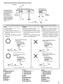
Important Tips on Bridging an Amplifier/Conseils importants lors de la mise en pont d'un amplificateur/Consejos importantes cuando conecte en puente un amplificador
NOTE:
The following problems may occur if the amp is
not properly connected.
1) Low output when only one input is used.
2) Premature overheating, resulting in the early
operation of the protection circuit, when only one
input is used.
3) The V-Adapter is not required if a line output,
stereo pair is used to drive both inputs of the
bridged amp.
o
REMARQUE:
Les problemes suivants peuvent survenir si I'amplificateur n'est pas correctement connecte.
1) Faible puissance lorsqu'une seule sortie est utilisee.
2) Surchauffe prematuree, d'oLJ la mise en marche
precoce du circuit de protection, lorsqu'une seule
sortie est utilisee.
3) L:adaptateur Y n'est pas necessaire si une sortie
de ligne ou un couple stereo sont utilises pour les
deux sorties de I'amplificateur ponte.
x
Proper connection/Connexion correcte/
Conexi6n correcta
NOTA:
Podrian ocurrir los siguientes problemas si el
amplificador no esta correctamente conectado.
1) Salida baja si s610 se utiliza una entrada.
2) Sobrecalentamiento prematuro que provoque el
funcionamiento anticipado del circuito de
protecci6n cuando s610 se utiliza una entrada.
3) EI adaptador-Y no es necesario si se utiliza una
pareja de salida en Ifnealestereo para conducir
ambas entradas del amplificador puenteado.
Improper connection/Connexion incorrecte/
Conexi6n incorrecta
(R)J
~
~
,
(L)
(One signal/Un signal/Una senal)
o
x
Proper connection/Connexion correcte/
Conexi6n correcta
~~
mc~~~
(R)
~
I
(One signal/Un signal/Una senal)
Improper connection/Connexion incorrecte/
Conexi6n incorrecta
(R)
~
rnc~~
(L)
(L)
(One signal/Un signal/Una senal)
Fig. 10
(One signal/Un signal/Una senal)
[English)
[Fran~ais)
[Espanol]
~ V-Adaptor (Sold Separately)
~ Adaptateur en forme de « V »
~ Adaptador en forma de "V"
f) RCA Extension Cable
(Sold Separately)
~ Front
~ Rear
~ Rear Speakers
f; Front Speakers
@) Speakers
~ Head Unit, etc.
~ Other AMP
(vendu separement)
f) Cable de rallonge RCA
(vendu separement)
~ Avant
~ Arriere
~ Haut-parleurs arriere
f; Haut-parleurs avant
@) Haut-parleurs
~ Unite principale, etc.
~ Autre amplificateur
(vendido por separado)
f) Cable de extension RCA
(vendido por separado)
~ Delantero
~ Trasero
~ Altavoces traseros
f; Altavoces delanteros
@) Altavoces
~ Unidad principal, etc.
~ Otro amplificador
13
• Speaker Input leads System/Systeme des conducteurs d'entree de haut-parleur/Sistema de conductores de entrada de altavoz
(Right sidel
Cote droit!
Lado derecho)
[!LJ
*~
10
4El
~ID
CiS
2
:s:
>.
'"
(5
0G)
ttl
<.'J
"""
>.
'"
~
CiS
<.'J
2
:c
FL
ttl
:s: FL
FR
ttl
""
"'"
m
~ FR
<'5 0
0
'"
m
c:
CD!
>~
I
;;
[QJ
«-,I ~~.
on
Low Pass/Passe-bas/Paso bajo
--"L
Off'"
FILTER
"""
Ci'"S
l'
~
(»
-0
~
<.'J
-'"
u
'"
m
c
(»
(»
c: RL
Qi
-0
~0
RLo
ttl
;;
<'5
~
@>
High Pass/Passe-hautlPaso alto
fll{R
;;
Q)
mil
~
Qi
-0
""u
~
""" 0
m
'" ~
~ttl
...... Full Range/Pleine bande/Pleno alcance
flLt(ll
(i)
A
t+l
:c
«-,I ~~.
I
NOTE/REMARQUE/NOTA:
OSpeaker Level Input Connector/Connecteur d'entnle de
niveau de haut-parleur/Coneclor de entrada de nivel
del altavoz
• See page RISe reporter a la page 8.Nea la pagina 8.
"""
'"
CiS
~
Q)
-0
;;
RR
o
e
Fig. 11
* Use either RCA line level or speaker level inputs. Do not connect both at the same time.!
a
Utiliser les entrees de niveau de ligne RCA ou de niveau de haut-parleur. Jamais les connecter la lois.!
Ulilice las entradas de nivel de altavoz 0 de nivel de linea RCA. No conecte las dos al mismo tiempo.
[English]
o
@)
f!l
~
~
fD
@l
V-Adaptor (Sold Separately)
RCA Extension Cable
(Sold Separately)
Front
Rear
Rear Speakers
Front Speakers
Speakers
Head Unit, etc.
~
~ Other AMP
14
[Espafiol]
[Fran~ais]
o
@)
f!l
~
~
fD
@l
~
~
Adaptateur en forme de
(vendu separement)
Cable de rallonge RCA
(vendu separement)
Avant
Arriere
Haut-parleurs arriere
Haut-parleurs avant
Haut-parleurs
Unite principale, etc.
Autre amplificateur
«
Y ..
o
@)
f!l
~
~
fD
@l
~
~
Adaptador en forma de uY"
(vendido por separado)
Cable de extension RCA
(vendido por separado)
Delantero
Trasero
Altavoces traseros
Allavoces delanteros
Altavoces
Unidad principal, etc.
Otro amplificador
• Pre-Out System/Systeme de sortie du preamplificateur/Sistema de salida del preamplificador
(Right side/
Cote droit!
Lado derecho)
lQ::J
--IlL
OFF
~p
Full Range/Pleine bande/Pleno alcance
LP
FILlEP
[Q]
--IlL
OfF
HP
LP
------ High Pass/Passe-haut!Paso alto
FILTER
[J::jJ
--IlL
Off
HP
lP
Low Pass/Passe-bas/Paso bajo
Fig. 12
[English)
[Fran~ais)
[Espanal]
$ V-Adaptor (Sold Separately)
$ Adaptateur en forme de « V »
$ Adaptador en forma de UV"
@) RCA Extension Cable
(Sold Separately)
fll Front
Q1 Rear
~ Rear Speakers
G Front Speakers
@) Speakers
@) Head Unit, etc.
@) Other AMP
(vendu separement)
@) Cable de rallonge RCA
(vendu separement)
fll Avant
Q1 Arriere
~ Haut-parleurs arriere
G Haut-parleurs avant
@) Haut-parleurs
@) Unite principale, etc.
@) Autre amplificateur
(vendido por separado)
@) Cable de extension RCA
(vendido por separado)
fll Delantero
Q1 Trasero
~ Altavoces traseros
G Altavoces delanteros
@) Altavoces
@) Unidad principal, etc.
@) Otro amplificador
15
English
Fran ais
Espatiol
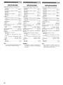
SPECIFICATIONS
SPECIFICATIONS
ESPECIFICACIONES
RMS Continuous Power (at 14.4 V, 20 - 20kHz)
• Per channel into 4 ohms (Sl% THD+N)
MRP-F600
100 W x 4
MRP-F300
50 W x 4
• Per channel into 2 ohms (Sl % THD+N)
MRP-F600 .
.
150 W x 4
MRP-F300
.
75 W x 4
• Briged 4 ohms (Sl% THD+N)
MRP-F600
..... 300W x 2
.... 150Wx2
MRP-F300
.
SIN Ratio
• IHF A Weighted, Reference: rated power into
4~~.
.100dM
• IHF A Weighted, CEA2006, Reference: lW into
4 ohms
80 dBA
Input Impedance
• RCA IN.
.
15k ohms
• SP IN
20k ohms
Frequency Response (+0, -1 dB)
20Hz - 20kHz
Crossover Frequency
• 1/2ch
50 - 400 Hz (-12dB/oct.)
50 - 400 Hz (-12dB/oct.)
• 3/4ch
Input Sensitivity (RCA IN) .
.
0.2 - 4 V
Subsonic Filter
.. 15Hz, Fixed
BASS EO
50Hz, +12dB(3/4ch), On/OH
Dimensions
• Width (Heat Sink I Footprint)
MRP-F600.
.... 320 mm (12 - 19/32")/380 mm (14 - 61/64")
MRP-F300
.
............ 210 mm (8 - 17/64")/270 mm (10 - 5/8")
• Height . . .
.
60 mm (2 - 23/64')
• Depth
242 mm (9 - 17/32")
Weight
MRP-F600
4.2 kg
MRP-F300
.
2.7 kg
Puissance continue RMS (a 14,4 V, 20 - 20kHz)
• Par canal sous 4 ohms (S1 % DHT+N)
MRP-F600
.
100 W x 4
MRP-F300
50 W x 4
• Par canal sous 2 ohms (Sl % DHT+N)
MRP-F600
150 W x 4
MRP-F300
.
75 W x 4
• Ponte 4 ohms (Sl % DHT+N)
MRP-F600
.
300W x 2
150W x 2
MRP-F300
.
Rapport SIB
• Pondere IHF A, Reference: puissance nominate
sous 4 ohms
... 100 dBA
• Pondere IHF A, CEA2006, Reference: lW
sous 4 ohms.
.... 80 dBA
Impedance d'entree
. 15k ohms
• RCA IN.
.
.
. 20k ohms
• SP IN ...
.. 20Hz - 20kHz
Reponse de frequence (+0, -ldB).
Frequence de recouvrement
·1/2can.
.
50 - 400Hz (-12dB/oct.)
50 - 400Hz (-12dB/oct.)
• 3/4can.
.
Sensibilite d'entree (RCA IN) .
... 0,2- 4 V
Filtre subsonique
.... 15Hz, Fixe
BASS EO .... 50Hz, + 12dB (3/4can.), Active/Desactive
Dimensions
• Largeur (Dissipateur thermique I Empreinte)
MRP-F600
.
..... 320 mm (12 - 19/32")/380 mm (14 - 61/64")
MRP-F300
.
. .. 210 mm (8 - 17/64")/270 mm (10 - 5/8")
• Hauteur
60 mm (2 - 23/64")
• Profondeur
242 mm (9 -17/32")
Poids
MRP-F600.
.......... 4,2 kg
MRP-F300.
....... 2,7 kg
Potencia continua RMS (a 14,4 V, 20 - 20kHz)
• Por canal en 4 ohmios (Sl % DHT+N)
MRP-F600
.
100 W x 4
MRP-F300.
.. 50Wx4
• Por canal en 2 ohmios (S1 % DHT+N)
MRP-F600
150 W x 4
MRP-F300
. 75 W x 4
• Ponte ado en 4 ohmios (Sl % DHT+N)
MRP-F600.
300W x 2
MRP-F300
.. 150Wx2
Relacion SIR
• IHF A ponderado, Referencia: potencia nominal
~4~m~.
.
100dM
• IHF A ponderado, CEA2006, Referencia: lW
en 4 ohmios ...
.... 80 dBA
Impedancia de entrada
• RCA IN .
... 15k ohmios
20k ohmios
• SP IN
.
Respuesta de frequencia (+0, -1dB)
20Hz - 20kHz
Frecuencia de corte
• 1I2can
50 - 400Hz (-12dB/oct.)
50 - 400Hz (-12dB/oct.)
• 3/4can.
.
Sensibilidad de entrada (RCA IN)
... 0,2 - 4 V
Filtro subsonico
15Hz, Fijo
BASS EO .... 50Hz, +12dB (3/4can.). Activado/Desactivado
Dimensiones
• Ancho (Disipador termico I Huella)
MRP-F600
.
......... 320 mm (12 - 19/32")/380 mm (14 - 61/64")
MRP-F300
.
..... 210 mm (8 - 17/64")/270 mm (10 - 5/8")
........................... 60 mm (2 - 23/64")
• Alto ..
................. 242 mm (9 - 17/32")
• Profundidad
Peso
MRP-F600 ..
.... 4,2 kg
MRP-F300.
................... 2,7 kg
NOTE:
REMAROUE:
NOTA:
For product improvement, specifications and design are subject to change without notice.
16
a
Afin d'ameliorer ce produit, les specifications et
la conception sont sujeltes a des modifications
sans preavis.
Con el prop6sito de introducir mejoras, las
especificaciones y el disefio del producto estan
sujetos a cam bios sin previo aviso.
SERVICE CARE
Espanol
Fran ais
English
SOINS PRATIQUES
CUIDADOS PRAcTICOS
IMPORTANT NOTICE
AVIS IMPORTANT
AVISO IMPORTANTE
This Amplifier has been type tested and found to comply with the limits for a Class B computing device in
accordance with the specifications in Subpart J of Part
15 of FCC Rules. This equipment generates and uses
radio frequency energy, and it must be installed and
used properly in accordance with the manufacturer's
instructions.
Cet amplificateur aete teste et est conforme aux Iimites
des dispositifs informatiques de categorie B,
conformement aux reglements du FCC, section 15,
soussection J. Ce materiel produit et utilise des hautes
frequences radio et doit etre installe et utilise
conformement aux directives du fabricant.
Este amplificador ha sido probado y es conforme con
los Ifmites de los dispositivos informaticos de categoria
B, segun la regulaci6n de FCC, secci6n 15, subsecci6n
J. Este equipo produce y utiliza altas frecuencias radio
y debe ser instalado y utilizado segun las instrucciones
del fabricante.
SERIAL NUMBER:
INSTALLATION DATE:
INSTALLATION TECHNICIAN:
PLACE OF PURCHASE:
NUMERO DE SERlE:
DATE D'INSTALLATION :
INSTALLATEUR :
LIEU D'ACHAT :
NUMERO DE SERlE:
FECHA DE INSTALACION:
TECNICO:
LUGAR DE ADQUISICION:
IMPORTANT
IMPORTANT
IMPORTANTE
Please record the serial number of your unit in the
space provided here and keep it as a permanent
record. The serial number plate is located on the
rear of the unit.
Enregistrer Ie numero de serie de I'appareil dans
I'espace prevu ici et Ie conserver en permanence.
La plaque de numero de serie est situee aI'arriere
de I'apparei!.
Anote el numero de serie de su unidad en el espacio
proporcionado aqui, y conservelo como un registro
permanente. La placa con el numero de serie esta
ubicada en la parte posterior de la unidad.
17
NO POSTAGE
NECESSARY
IF MAILED
INTHE
UNITED STATES
BUSINESS REPLY MAIL
FIRST-CLASS MAIL' PERMIT NO. 320
TORRANCE CA
POSTAGE WILL BE PAID BY ADDRESSEE
ATIENTION MARKETING SERVICES
ALPINE ELECTRONICS OF AMERICA INC
PO BOX 2859
TORRANCE CA 90509-9939
1111111111111111111111111111111111111111111111111111
i FOR USE IN USA, PLEASE FOLD HERE AND ENSURE THAT
AMERICAN ADDRESS FACES UP.
'dn S3:J'V.:! SS3l:l00'V N'VIO'VN'V:J
1'VH13l:lnSN3 ON'V 3l:l3H ala.:! 3S'V31d VO'VN'V:J NI 3sn l:lO.:!
t
1111111111111111111111111111111111111111"1111111111
V81~3V\1V .:10 S3.iV.iS 03.iINn
9LB6-~0906 V'J 3'JN~~0.i
ld
A'J~3V\1V~8 9v~6~
S'JINO~.i'J313
3NldlV
-.-v AllIVd _11M J5YlIlW
BAVd DNlJd)HIlWl AltDH SSltlSll81VNOliVNH)ltl
-
mllNll:J:I/S.
mVlUD. .
~
)UD
11IIII1
AmRIII
J5YUId.
IaIVIHV lid.
-.
IIII11
BIl1
~ALPINE.
Customer Care Registration
~ For easy on-line registration, go to ··www.alpine-usa.col11/registration ..
Thank you for choosing Alpine! Please register your product with us so we can serve you better.
First name:
_
Last name:
III Product purchased
1.0 Cassette Player
2.0 CD Player
3.0 MD Player
4.0 DVD Player
5.0 CD Changer
6.0 Amplifier
7.0 Speaker
8.0 Subwoofer
_
Home address:
"'St='e"'et"""'ad""d=res=s------------
City
State/Provo
Zip Code
May we contact you at this address?
1.0 Yes 2.0 No
Phone number: (
• Model Number:
------------==-------==-1.0 Yes 2.0 No
May we contact you at this number?
w
a:
w
:::I:
..J
«
w
en
-----------=,...----==-May we contact you bye-mail?
1.0 Yes 2.0 No
• Gender
1.0 Male
• Date of Birth Month:
• Marital Status
Year:
1.0 Single
=----
2.0 Married
• Which ethnicity best describes yourself:
1. 0 Caucasian
2.0 Hispanic
3. 0 African-American
4. 0 Asian
5.0 Other
_
• Your highest level of education completed:
1.0 High School Student
2.0 High School Graduate
3. 0 2 Yr. Degree/Some College
4.0 Completed 4 Yr. College
5.0 Completed Graduate School
0>
}
2.0 Female
1.0Yes
J.
_
• Date of Purchase:
• If navigation system, which monitor?
1.0 Alpine ~ (Model No.)
_
------------
• Purpose of buying this unit?
1.0 Addition
2.0 Replacement ~ *Previous brand replaced?
1.0 Factory installed
2.0 Alpine
3.0 Other
_
• Have you purchased Alpine products before?
1. 0 First time
Thank you for your cooperation I We value your privacy. This information will remain confidential with Alpine and its affiliates.
2.0 Two or more times
1.0 I usually have more electronic equipment than my friends
2.0 I am usually one of the first of my friends to buy the newest
electronic equipment
3. 0 I usually wait until a product has been out for a while before
I purchase it
4. 0 I am usually on of the first of my friends to know about the
newest car
5.0 I usually know more about cars than my friends
• Occupation
Year:
2.0 Other ~ (Brand Name)
_
• Which of the following statements best describes you?
_
Month:
2.0No.
(Brand Name)
_
• Serial Number:
E-mail Address:
I!iVWhen you purchased this Alpine unit, did you
compare it with other brands?
9. 0 Monitor Controller
10.0 Video Monitor
11 . 0 Navigation
12.0 Mobile Mayday
13.0 Video Tape Player
14.0 Processor/Equalizer
15.0 Security
16.0 Other
6. ~ EngineeringlTechnical
7.
Farming/Fishing
8.
Retired
9.
Student
10.0 Other
_
1. 0 Executive/Managerial
2.0 Secretarial/Clerical
3. 0 Sales
4. 0 General Labor
5. 0 Professional
en
m
»
r:::I:
m
m
:II
8
• Household Income
1.0 Less than $30,000
2.0 $30,000 - $50,000
3.0 $50,000 - $70,000
4.
$70,000 - $90,000
5.
$90,000 - $110,000
6.0 Over $110,000
• Type of vehicle in which this unit is installed.
Make:
Purchased Year:
Model:
_
_
Model Year:
_
• How was this vehicle purchased?
1.0 Bought
Customer Care Registration is for Product registration.
Failure to complete and return this card does not diminish your warranty rights.
2.0 Leased
PART NO. 68P04190K17-A
M3544084010
/ffffALPINE"
LIMITED WARRANTY
ALPINE ELECTRONICS OF AMERICA, INC. AND ALPINE OF CANADA INC. ("Alpine"), are dedicated to quality craftsmanship and are pleased to
offer this Warranty. We suggest that you read it thoroughly. Should you have any questions, please contact your Dealer or contact Alpine at one of
the telephone numbers listed below.
• PRODUCTS COVERED:
.HOW WE LIMIT IMPLIED WARRANTIES:
This Warranty covers Car Audio Products and Related Accessories
("the product"). Products purchased in the Canada are covered only in
the Canada. Products purchased in the U.S.A. are covered only in the
U.S.A.
ANY IMPLIED WARRANTIES INCLUDING FITNESS FOR USE AND
MERCHANTABILITY ARE LIMITED IN DURATION TO THE PERIOD
OF THE EXPRESS WARRANTY SET FORTH ABOVE AND NO
PERSON IS AUTHORIZED TO ASSUME FOR ALPINE ANY OTHER
LIABILITY IN CONNECTION WITH THE SALE OF THE PRODUCT.
.LENGTH OF WARRANTY:
This Warranty is in effect for one year from the date of the first
consumer purchase.
.WHO IS COVERED:
This Warranty only covers the original purchaser of the product, who
must reside in the United States, Puerto Rico or Canada.
.WHAT IS COVERED:
This Warranty covers defects in materials or workmanship (parts and
labor) in the product.
.WHAT IS NOT COVERED:
This Warranty does not cover the following:
CD Damage occurring during shipment of the product to Alpine for
repair (claims must be presented to the carrier).
Damage caused by accident or abuse, including burned voice coils
caused by over-driving the speaker (amplifier level is turned up and
driven into distortion or clipping). Speaker mechanical failure (e.g.
punctures, tears or rips). Cracked or damaged LCD panels.
Dropped or damaged hard drives.
@ Damage caused by negligence, misuse, improper operation or
failure to follow instructions contained in the Owner's manual.
@ Damage caused by act of God, including without limitation,
earthquake, fire, flood, storms or other acts of nature.
Any cost or expense related to the removal or reinstallation of the
product.
® Service performed by an unauthorized person, company or
association.
® Any product which has the serial number defaced, altered or
removed.
(j) Any product which has been adjusted, altered or modified without
Alpine's consent.
® Any product not distributed by Alpine within the United States,
Puerto Rico or Canada.
® Any product not purchased from an Authorized Alpine Dealer.
®
.HOW WE EXCLUDE CERTAIN DAMAGES:
ALPINE EXPRESSLY DISCLAIMS LIABILITY FOR INCIDENTAL AND
CONSEQUENTIAL DAMAGES CAUSED BY THE PRODUCT. THE
TERM "INCIDENTAL DAMAGES" REFERS TO EXPENSES OF
TRANSPORTING THE PRODUCT TO THE ALPINE SERVICE
CENTER, LOSS OF THE ORIGINAL PURCHASER'S TIME, LOSS OF
THE USE OF THE PRODUCT, BUS FARES, CAR RENTALS OR
OTHERS COSTS RELATING TO THE CARE AND CUSTODY OF
THE PRODUCT. THE TERM "CONSEQUENTIAL DAMAGES"
REFERS TO THE COST OF REPAIRING OR REPLACING OTHER
PROPERTY WHICH IS DAMAGED WHEN THIS PRODUCT DOES
NOT WORK PROPERLY. THE REMEDIES PROVIDED UNDER THIS
WARRANTY ARE EXCLUSIVE AND IN LIEU OF ALL OTHERS.
.HOW STATE/PROVINCIAL LAW RELATES TO THE
WARRANTY:
This Warranty gives you specific legal rights, and you may also have
other rights which vary from state to state and province to province. In
addition, some states/provinces do not allow limitations on how long an
implied warranty lasts, and some do not allow the exclusion or
limitation of incidental or consequential damages. Accordingly,
limitations as to these matters contained herein may not apply to you.
.IN CANADA ONLY:
This Warranty is not valid unless your Alpine car audio product has
been installed in your vehicle by an Authorized Installation Center, and
this warranty stamped upon installation by the installation center.
.HOW TO CONTACT CUSTOMER SERVICE:
Should the product require service, please call the following number for
your nearest Authorized Alpine Service Center.
CAR AUDIO 1-800-ALPINE-1 (1-800-257-4631)
NAVIGATION 1-888-NAV-HELP (1-888-628-4357)
Or visit our website at; http://www.alpine-usa.com
.HOW TO OBTAIN WARRANTY SERVICE:
CD You are responsible for delivery of the product to an Authorized
Alpine Service Center or Alpine for repair and for payment of any
initial shipping charges. Alpine will, at its option, repair or replace
the product with a new or reconditioned product without charge. If
the repairs are covered by the warranty, and if the product was
shipped to an Authorized Alpine Service Center or Alpine, Alpine
will pay the return shipping charges.
® You should provide a detailed description of the problem(s) for
which service is required.
@ You must supply proof of your purchase of the product.
@ You must package the product securely to avoid damage during
shipment. To prevent lost packages it is recommended to use a
carrier that provides a tracking service.
ALPINE ELECTRONICS OF AMERICA, INC., 19145 Gramercy Place, Torrance, California 90501, U.S.A.
ALPINE ELECTRONICS OF CANADA, INC., 777 Supertest Road, Toronto, Ontario M3J 2M9, Canada
Do not send products to these addresses.
Call the toll free telephone number or visit the website to locate a service center.