1
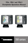
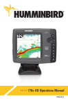
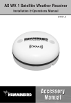
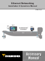
Ethernet Networking
Installation & Operations Manual
531906-1EN_B
GPS
Unit 1
Unit 2
HUMMINBIRD®
ETHERNET
Thank You!
Thank you for choosing Humminbird®, America's #1 name in Fishfinders.
Humminbird® has built its reputation by designing and manufacturing
top-quality, thoroughly reliable marine equipment. Your Humminbird®
accessory is designed for trouble-free use in even the harshest marine
environment. In the unlikely event that your Humminbird® accessory does
require repairs, we offer an exclusive Service Policy - free of charge during the
first year after purchase, and available at a reasonable rate after the
one-year period. For complete details, see the separate warranty card included
with your accessory. We encourage you to read this operations manual
carefully in order to get full benefit from all the features and applications of
your Humminbird® product.
Contact our Customer Resource Center at 1-800-633-1468 or visit our
Web site at humminbird.com.
WARNING! This device should not be used as a navigational aid to prevent collision,
grounding, boat damage, or personal injury. When the boat is moving, water depth
may change too quickly to allow time for you to react. Always operate the boat at
very slow speeds if you suspect shallow water or submerged objects.
WARNING! The electronic chart in your Humminbird® unit is an aid to navigation
designed to facilitate the use of authorized government charts, not to replace them.
Only official government charts and notices to mariners contain all of the current
information needed for the safety of navigation, and the captain is responsible for
their prudent use.
WARNING! Disassembly and repair of this electronic unit should only be performed
by authorized service personnel. Any modification of the serial number or attempt to
repair the original equipment or accessories by unauthorized individuals will void the
warranty.
WARNING! This product contains chemicals known to the State of California to
cause cancer and/or reproductive harm.
i
NOTE: Some features discussed in this manual require a separate purchase, and
some features are only available on international models. Every effort has been made
to clearly identify those features. Please read the manual carefully in order to
understand the full capabilities of your model.
NOTE: The Ethernet accessory is compatible with many Humminbird® models,
and every effort has been made to note the differences between the models and
functions throughout this manual. The illustrations in this manual may look
different than your display, but your model will operate in a similar way.
700 Series™, 800 Series™, 900 Series™, 1100 Series™, Cannon®, CannonLink™, Contour XD™,
Down Imaging™, DualBeam PLUS™, Fish ID+™, HumminbirdPC™, Humminbird®, InterLink™,
QuadraBeam PLUS™, RTS™ Window, Side Imaging®, SwitchFire™, Structure ID®, UniMap™,
WeatherSense®, WhiteLine™, and X-Press™ Menu are trademarked by or registered trademarks of
Humminbird®.
© 2011 Humminbird®, Eufaula AL, USA. All rights reserved.
ii
Table of Contents
Introduction
1
1. Installing an Ethernet Connection
2
2. Powering On
7
3. Configuring the Ethernet Network
8
Configuration Overview
8
Network Menu Tab . . . . . . . . . . . . . . . . . . . . . . . . . . . . . . . . . . . . . . . . . . . . . . . 10
Customize the Unit Name
11
Open the Network Source Setup Dialog Box
12
Sonar Source Overview
13
Select a Sonar Source . . . . . . . . . . . . . . . . . . . . . . . . . . . . . . . . . . . . . . . . . . . . . 14
Change the Sonar Source . . . . . . . . . . . . . . . . . . . . . . . . . . . . . . . . . . . . . . . . . . 16
Temperature Source Overview
17
Select a Temperature Source . . . . . . . . . . . . . . . . . . . . . . . . . . . . . . . . . . . . . . . 18
Change the Temperature Source . . . . . . . . . . . . . . . . . . . . . . . . . . . . . . . . . . . . 21
GPS and Sharing Waypoints Overview
23
Select a GPS Source . . . . . . . . . . . . . . . . . . . . . . . . . . . . . . . . . . . . . . . . . . . . . . 24
Change the GPS Source . . . . . . . . . . . . . . . . . . . . . . . . . . . . . . . . . . . . . . . . . . . 26
Share Waypoints . . . . . . . . . . . . . . . . . . . . . . . . . . . . . . . . . . . . . . . . . . . . . . . . 27
Restore Defaults (Setup Menu Tab)
28
iii
Table of Contents
Troubleshooting
29
Fishing System Doesn’t Power Up. . . . . . . . . . . . . . . . . . . . . . . . . . . . . . . . . . . 29
Fishing System Defaults to Simulator with a Transducer Attached. . . . . . . . . 30
Humminbird® Accessories
31
Contact Humminbird®
33
iv
Introduction
This manual will guide you through the following network setup instructions:
1. Connect two Humminbird® units together
2. Power On
3. Configure your Humminbird® Ethernet Network
4. Share Waypoints
Alarms, navigation, sonar data, and the menu system are all affected
by the Ethernet network settings. We encourage you to read this
manual completely so that you may understand the full capabilities of
your Humminbird® Ethernet network.
1
Introduction
1. Installing an Ethernet Connection
If your Humminbird® control head has a built-in Ethernet connector, the unit
can be connected to the Ethernet network. When you connect the units
together, data is shared between the two units.
Before you start, please note that the Ethernet network installation has the
following requirements:
• Update Software: If your network includes a legacy Humminbird®
model, download the latest software update from your account at
humminbird.com. Legacy models include 858c, 898c SI, 998c SI, 958c,
and 1100 Series™ units.
• Install the control heads and sources (GPS, transducers, temp/speed
accessories, etc.) for your Fishing System. See the equipment installation
guides for details.
• Purchase Ethernet Connection Cables (separate purchase required):
Your network configuration will determine which Humminbird®
connection cables you will need to purchase to connect the control
heads to the network (see the Ethernet Cable Information table).
Installation
2
Ethernet Cable Information
Control Heads
Required Cables
(2) 700 Series™ Units
(2) AS EC QDE & (1) AS EC [length]E
(1) 700 Series™ Unit &
(1) 800/900/1100 Series™ Unit
(1) AS EC QDE & (1) AS EC [length]E
(2) 800, 900, or 1100 Series™ Units
(1) AS EC [length]E
NOTE: The AS EC [length]E cable is available in a variety of lengths. To purchase the
Ethernet Connect Cables or extension cables, visit our Web site at humminbird.com or
call our Customer Resource Center at 1-800-633-1468 for details.
Connect the Control Heads
1. Confirm that the control heads are powered off.
2. To install the Ethernet cables, see the connection information for
your network configuration as follows:
• Two 700 Series™ Units: see Section A.
• One 700 Series™ Unit & One 800/900/1100 Series™ Unit:
see Section B.
• Two 800, 900, or 1100 Series™ Units: see Section C.
NOTE: The AS EC [length]E cable is available in a variety of lengths. The following
instructions use AS EC 10E, but your cable part number may be different.
NOTE: You may need to consult your control head installation guide for details.
3
Installation
700 Series™ Quick Disconnect Mount Cable Collector
Ethernet
A. Two 700 Series™ Units
1. Insert the AS EC QDE Ethernet cable connector into the
Ethernet slot on the 700 Series™ cable collector. Repeat this
step for the second AS EC QDE cable.
NOTE: The 700 Series™ control head uses a cable collector for the Quick
Disconnect Mount and the In-Dash Mount. See your control head installation
guide for details.
2. Connect the AS EC 10E to each round connector on the
AS EC QDE cables.
3. Hand-tighten the screw nut(s) on each cable to secure the
connection. The connectors are keyed to prevent incorrect
installation, so be careful not to force the connectors.
B. One 700 Series™ Unit & One 800/900/1100 Series™ Unit
1. Insert the AS EC QDE Ethernet cable connector into the
Ethernet slot on the 700 Series™ cable collector.
NOTE: The 700 Series™ control head uses a cable collector for the Quick
Disconnect Mount or the In-Dash Mount. See your control head installation guide
for details.
2. Insert one end of the AS EC 10E cable into the Ethernet port on
the back of the 800/900/1100 Series™ control head. The
connectors are keyed to prevent incorrect installation, so be
careful not to force the connectors into the port.
Installation
4
3. Connect the AS EC QDE cable connector to the AS EC 10E cable
connector.
4. Hand-tighten the screw nut(s) on each cable to secure the
connection.
Hand-Tightening the Screw Nut
Screw
Nut
The connector is
keyed to prevent
incorrect installation.
C. Two 800, 900, or 1100 Series™ Units
1. Insert one end of the AS EC 10E cable into the Ethernet port on
the back of the first control head. The connectors are keyed to
prevent incorrect installation, so be careful not to force the
connectors into the port.
2. Insert the other end of the AS EC 10E cable into the Ethernet
port on the second control head.
3. Hand-tighten the screw nut(s) on each cable to secure the
connection.
5
Installation
800/900 Series™ (rear view)
Ethernet Port
1100 Series™ (rear view)
Installation
6
2. Powering On
When you have installed an Ethernet network, the power on process is the
same as powering on a single control head, however, your transducer
connections will determine how the control head starts normal operation. It is
important to set up your network to use the correct sources.
If there is a transducer connected to only one of the control heads,
and you intend to share the transducer on the network, power on
the control head with the connected transducer first.
Power On
1. Press the
POWER/LIGHT key.
Operation Mode: If a transducer is attached to the control head,
Normal mode (for on-the-water use) will start automatically. This is the
default operation for powering on the control head, but the network
setup will vary with how you’ve set up the connections as follows:
• If a transducer is not attached to the control head, but there is
another transducer connected to the network, the control head
will detect the other transducer and use it to start Normal mode
automatically.
• If a transducer is not attached to the control head, but there is
more than one transducer connected to the network, follow the
on-screen instructions to choose a transducer source. See Select
a Sonar Source for more information.
NOTE: Also, see your control head operations manual for more information about
the Start-Up Options Menu.
2. Repeat steps 1 until all of the control heads in the network are
powered on. The Fishing System will detect the other control heads
and sources in the network.
NOTE: If you have an InterLink™ connected to the network, the Ethernet will disable
the InterLink™ because both network systems cannot be used at the same time.
7
Powering On
3. Configuring the Ethernet Network
Set up your Humminbird® Ethernet Network using the following instructions,
including these topics:
1. Network Setup Overview
2. Customize the Unit Name
3. Select Data Sources (transducer, temperature, GPS receiver)
for each control head
4. Understand the Shared and Local Menu Settings
5. Share Waypoints
Configuration Overview
Connected (and powered) units can detect the other control heads and sources
on the network. When the units are connected for the first time, the sources
(transducer, temperature, and GPS) default to Local operation.
Local (default): The source reports data only to the connected control
head.
Shared: The source is set up to report data to both control heads in the
network so that they share the same data.
It is important to note that when a source is shared on the network,
the source’s data will be synchronized between units. The Menu
System and View Rotation will change to match the shared source’s
capabilities. Review each source section to understand how a
shared source will affect your Fishing System.
Configuration Overview
8
Example of a Network Configuration
GPS (Shared)
Note that the Speed Digital Readout is
the same on both control head views
1198c SI
788ci HD
Ethernet
Speed
Digital Readout
Speed
Digital Readout
Side Imaging® Transducer
(Local)
It will only report data
to the 1198c SI.
9
DualBeam PLUS™
Transducer
(Local)
It will only report data
to the 788ci HD.
Configuration Overview
Network Menu Tab
When units are connected on the
network, the Network menu tab is added
to the Main Menu system.
The Network menu tab includes the following menu options:
Unit Name: Displays the name of the control head. The default Unit
Name is based on its model number and serial number. To change the
Unit Name, see Customize the Unit Name.
Network Source Setup: Opens the Network Source Setup dialog box.
Use this dialog box to review all the sources connected to the network.
You can also select sources for Local or Shared networking with this
dialog box.
Share Waypoints: Turn on this menu option to share waypoints (see
GPS and Sharing Waypoints Overview and Share Waypoints).
Configuration Overview
10
Customize the Unit Name
Each control head is assigned a Unit Name, which is based on its model
number and serial number. The unit name is also displayed next to a source
name in the Network Source Setup dialog box so you can see where the source
is connected.
When you’re first setting up your network, you may want to change how the
unit name is displayed, so it is easier to identify each unit on the network.
Unit Name Dialog Box
Name Field
Use the 4-WAY Cursor
Control key to change the
unit name.
Select Save and press
the RIGHT Cursor key.
Customize the Unit Name
1. Main Menu: Press the MENU key twice. Select the Network menu
tab.
2. Select Unit Name. Press the RIGHT Cursor key. The unit name is
displayed in the dialog box.
3. Use the 4-WAY Cursor Control key to select the Name field. You can
change the control head display name as follows:
Move within the Name Field: Press the RIGHT or LEFT Cursor key.
Change a Letter or Number: Press the UP and DOWN Cursor keys. All
upper and lower case letters are available (including digits 0-9 and
some punctuation characters).
Save: Use the 4-WAY Cursor Control key to choose Save, and then
press the RIGHT Cursor key.
11
Configuration Overview
Open the Network Source Setup Dialog Box
The Network Source Setup dialog box displays all of the sources connected to
the network. The sources may be shared on the network or operating locally
with their connected control head.
Open the Network Source Setup Dialog Box
1. Main Menu: Press the MENU key twice. Select the Network tab.
2. Select Network Source Setup. Press the RIGHT Cursor key.
3. Status Tab: Allows you to review the selected data sources on the
network. If a source is grayed out, the source is selected, but the
network cannot detect the connection.
4. Select a Source: Review each source section in this manual to select
a data source for each control head and understand how a shared
source will affect your fishing system.
Network Source Setup Dialog Box
Source Tabs
Status Tab
Grayed-out Source:
The selected
transducer
connection is lost
or not found.
Temperature
sources
available from
transducers
and accessories
GPS Receiver
Data
Categories
Column
Configuration Overview
Selected
Sources
Column
If the Unit Name is changed, the
new name will be displayed here.
See Customize Unit Name.
12
Sonar Source Overview
When you select a new transducer source, the alarms, menu settings, view
rotation, and digital readouts will automatically update on the control head.
• Menu Settings: If the sonar source is shared, the control heads will
synchronize menu settings (Shared), while other menu settings will
continue to operate individually (Local) on each control head. When
you change a shared menu setting on one control head, it will be
updated on the other control heads that are sharing the source.
• Views: The view rotation will update to display views that are
compatible with the selected transducer.
• Alarms: When Sonar sources are shared on the network, the alarms
are also shared. The shared alarm settings can be controlled from either
control head, and the alarms will display or sound on both control
heads. To turn off a shared alarm, press the EXIT key on any control
head.
NOTE: If a selected transducer is not compatible with the control head, only limited
menu options and views will be added to the menu system.
Shared Sonar Menu Settings
Beam Select
Lower Range
SI Range
Depth Alarm
Max Depth
SwitchFire™
Depth Offset
Noise Filter
Water Type
Fish ID+™
Ping Rate
Units- Depth
Fish ID Sensitivity
13
Sonar Sources
Local Sonar Menu Settings
83 kHz Sensitivity
Quad Layout
Sonar Colors
455 kHz Sensitivity
RTS Window™
Ping Rate
Bottom Lock
Sensitivity (Down)
SI Range
Bottom Range
SI Colors
SwitchFire™
Bottom View
SI Enhance
Transducer Select
Chart Speed
SI Sensitivity
Upper Range
Depth Lines
SI Side
Water Type
NOTE: The Shared and Local menu options may change to accommodate new product
features.
Select a Sonar Source
When you first set up the network, the control head will automatically start
Normal operation with the transducer that is connected to it. Use the
instructions below to choose a different local sonar source or shared source for
your control head.
Select a Sonar Source
1. Open the Network Source Setup dialog box.
2. Press the RIGHT Cursor key until the Sonar tab is selected.
3. Scroll: Press the DOWN or UP Cursor keys. The selected source is
highlighted in white.
NOTE: If you do not see a connected transducer in the list, make sure that the control
head Transducer Select menu option is set to the correct transducer. Go to the
Main Menu > Sonar Menu Tab > Transducer Select.
Sonar Sources
14
4. Select: Press the RIGHT Cursor key. The check mark indicates that the
source is being used by the control head.
5. Save: Press the EXIT key twice to close the dialog box. Network
settings are saved even after the unit is powered off.
Local Setup (default): To use separate transducers for each control
head, repeat steps 1 - 5 on each control head until you’ve set a
transducer for each unit.
Shared Setup: To use the same transducer with more than one control
head, repeat steps 1 - 5 on each control head and select the same
transducer for all units.
Menu System and Views: When you select a sonar source, the
control head updates with the corresponding menu options and views.
If the transducer is shared between control heads, it may take a
moment for the data to synchronize. See Sonar Source Overview for
more information.
Selecting a Transducer
Press the
RIGHT or LEFT
Cursor key to
select a tab.
Selected
The check mark
indicates the
transducer is used
by the control head.
Available
Sonar Sources
Unit Name
Column
(see Customize
the Unit Name)
Unit Model
Number
Column
Transducer
Model
Column
15
Beam
Frequencies
Column
Empty
The empty box
indicates the
transducer data is
available but not
selected. You must
select a transducer
to display its data
on the control head.
Sonar Sources
Change the Sonar Source
To change the sonar source, open the Network Source Setup dialog box and
change the transducer source at any time (see Select a Sonar Source).
Network settings are saved even after the unit is powered off.
If the control head cannot detect the set transducer, an error message
displays so that you can reset the transducer source as follows:
• If the shared transducer is not detected on the network, the control
head will switch automatically to the local transducer. Follow the onscreen instructions to permanently save the local transducer as the
selected source.
• If the local transducer is not detected, follow the on-screen
instructions to switch to another transducer in the network. If there is
more than one transducer in the network, you can select a different
transducer from the Network Source Setup dialog box. See Select a
Sonar Source for details.
Finding the Sonar Source (700 Series™)
If the control head cannot detect the shared transducer, follow the on-screen
instructions to change the sonar source. Press the LEFT Cursor key to select No, or press
the RIGHT Cursor key to select Yes.
Sonar Sources
16
Temperature Source Overview
When you select a new temperature source, the alarms, menu settings, view
rotation, and digital readouts will automatically update on the control head.
• Menu Settings: If the temperature source is shared, the control heads
will synchronize menu settings (Shared), while other menu settings will
continue to operate individually (Local) on each control head. When
you change a shared menu setting on one control head, it will be
updated on the other control heads that are sharing the source.
• Views: The view rotation will update to display views or digital
readouts that are compatible with the selected temperature source.
• Alarms: When temperature sources are shared on the network, the
alarms are also shared. The shared alarm settings can be controlled
from either control head, and the alarms will display or sound on both
control heads. To turn off a shared alarm, press the EXIT key on each
control head.
Shared Temperature Menu Settings
Temp. Alarm
Units - Temp
Aux. Temp Alarm
NOTE: The remaining temperature menu options are controlled locally. The Shared and
Local menu options may change to accommodate new product features.
17
Temperature Sources
Select a Temperature Source
Temperature sources can be detected from a transducer’s built-in temperature
feature or from optional-purchase temperature/speed accessories connected
to the network.
• Default: When you first set up the network, the control head will
automatically choose the locally connected temperature source to
display digital readouts on the screen.
• Temperature Tabs: The T1, T2, T3, and T4 tabs at the top of the
Network Source Setup dialog box represent the digital readout
positions on the screen. You can choose a different temperature source
for each digital readout box, so each control head can display up to four
temperature digital readouts on the display.
NOTE: There will be less than four temperature tabs displayed if there aren’t four
temperature sources connected to the network.
Temperature Readout Sources
Press the
RIGHT or LEFT
Cursor key to
select a tab.
Temperature Tabs
Available
Temperature
Sources
The Temperature Source tabs correspond with the
digital readout positions on the screen.
Temperature Sources
18
Temperature Digital Readouts
1100 Series™
The Temperature Digital Readout positions correspond
with the T1, T2, T3, and T4 tabs in the Network Source
Setup dialog box.
Select Temperature Sources for Digital Readout Boxes
1. Open the Network Source Setup dialog box.
2. Select the tab for T1, T2, T3, or T4: Press the RIGHT or LEFT Cursor
keys. Each tab represents a digital readout position on the screen.
NOTE: The temperature readout positions may vary with the Humminbird® model. See
the Views section and Select Readouts section of your Humminbird® Operations Manual
for more information.
3. Scroll: Press the DOWN or UP Cursor keys. The selected source is
highlighted in white.
4. Select: Press the RIGHT Cursor key. The check mark indicates that the
source is being used by the control head.
5. Repeat steps 2 - 4 to select a different temperature tab.
19
Temperature Sources
6. Save: Press the EXIT key twice to close the dialog box. Network
settings are saved even after the unit is powered off.
Local Setup: To use separate temperature sources for each control
head, repeat steps 1 - 6 on each control head until you’ve set a
temperature source for each unit and each digital readout.
Shared Setup: To use the same temperature sources on more than
one control head, repeat steps 1 - 6 on each control head and select
the same temperature sources on all units.
Menu System: When you select a temperature source, the control
head updates with the corresponding menu options and views. If the
source is shared between control heads, it may take a moment for the
data to synchronize. See Temperature Source Overview for more
information.
Selecting a Temperature Source
for Digital Readout Position 1
Temp 1 tab sets
the temperature
source for
digital readout 1
on the screen.
Selected
The check mark
indicates the
source is used by
the control head.
The control
head detects
all of the
temperature
sources in the
network.
Unit Name
Column
(see Customize
the Unit Name)
Temperature Sources
Unit Model
Temperature Source
Number
Type Column
Column (from transducers or accessories)
20
Empty
The empty box
indicates the
temperature data
is available but not
selected. You must
select a temperature
source to display its
data on the control
head.
Temperature Graph
1100 Series™
Temperature Graph
(Source: Temp. 1)
Red marks
indicate where
the temperature
source changed.
Change the Temperature Source
To change the temperature source after the network has been configured,
open the Network Source Setup dialog box to change the temperature sources
at any time (see Select a Temperature Source). Network settings are saved
even after the unit is powered off.
• Temperature Graph (1100 Series™): Temperature Source 1 provides
the data for the temperature graph on the display. When the
temperature source is changed, the temperature graph displays a red
mark to show where the temperature source was changed.
NOTE: The Temperature Graph menu setting is not shared on the network. It is a
local menu setting.
• If the control head cannot detect the set temperature source, the
digital readout box will flash. If the digital readout box is blank, the
source has been lost. Open the Network Source Setup dialog box to
assign a temperature source to the digital readout box. See Select a
Temperature Source for details.
21
Temperature Sources
Temperature Source Lost
1100 Series™
The Temp 2 (T2) Source
is not detected on the network.
Temperature Sources
22
GPS and Sharing Waypoints Overview
When you select a new GPS source, the position, menu settings, view rotation,
and digital readouts will automatically update on the control head. To view
waypoint data on the network, it is important to understand the GPS source
and how to share waypoint data.
• Menu Settings: If the GPS source is shared, the control heads will
synchronize menu settings (Shared), while other menu settings will
continue to operate individually (Local) on each control head. When
you change a shared menu setting on one control head, it will be
updated on the other control heads that are sharing the GPS source.
• Views: The view rotation will update to correspond with the GPS
receiver. If a networked control head is not a chartplotter, it will display
chart information in trackplotter format (if it is trackplotter-capable).
• Navigation: Waypoint data can be shared, and you can build a route
on either control head with the shared waypoints. See Share
Waypoints for more information.
23
GPS & Sharing Waypoints Overview
Select a GPS Source
When you power on the network for the first time, the control head will
automatically choose the connected or internal GPS receiver to provide data to
the control head. Use the instructions below to select a GPS source for your
control head.
Select a GPS Source
1. Open the Network Source Setup dialog box.
2. Select the GPS Tab: Press the RIGHT Cursor key until the tab is
selected.
3. Scroll: Press the DOWN or UP Cursor keys. The selected source is
highlighted in white.
4. Select: Press the RIGHT Cursor key. The check mark indicates that the
source is being used by the control head.
5. Save: Press the EXIT key twice to close the dialog box. Network
settings are saved even after the unit is powered off.
Local Setup: To use separate GPS receivers for each control head,
repeat steps 1 - 5 on each control head until you’ve set a GPS receiver
for each unit.
Shared Setup: To use the same GPS receiver with more than one
control head, repeat steps 1 - 5 on each control head and select the
same GPS receiver on all units.
Menu System: When you select a GPS source, the control head
updates with the corresponding menu options and views. If the GPS is
shared between control heads, it may take a moment for the data to
synchronize. See GPS and Sharing Waypoints Overview for more
information.
GPS Sources
24
Selecting a GPS Source
GPS tab
Selected
The check mark
indicates the
source is used by
the control head.
The control
head detects
all of the GPS
sources in the
network.
Empty
The empty box
indicates the GPS
data is available
but not selected.
Unit Name
Column
(see Customize
the Unit Name)
Unit Model GPS Type
Number
Column
Column
(Internal or
External)
GPS Fix
Column
NOTE: The current GPS Fix Type is reported as No Fix, Fixed, or Enhanced. An Enhanced
fix has been augmented using information from WAAS, EGNOS, or MSAS. An Enhanced
Fix is required for navigation.
25
GPS Sources
Change the GPS Source
To change the GPS source after the network has been configured, open the
Network Source Setup dialog box to change the GPS sources at any time.
Network settings are saved even after the unit is powered off.
If the control head cannot detect the set GPS receiver, the control head will
display an error message so that you can reset the GPS source as follows:
• If the shared GPS receiver is not detected, the control head will
switch automatically to the local GPS receiver. Follow the on-screen
instructions to permanently save the local GPS receiver as the selected
source.
• If the local GPS receiver is not detected, the GPS data will flash. If
there isn't data displayed in the digital readout box, the source has
been lost. See Select a GPS Source to select another GPS Receiver in
the network.
Finding the GPS Source
700 Series™
If the control head cannot detect the shared GPS Receiver set in the network, follow the
on-screen instructions to change the GPS source. Press the LEFT Cursor key to select No,
or press the RIGHT Cursor key to select Yes.
GPS Sources
26
Share Waypoints
To share waypoints on the network, turn on Share Waypoints on each control
head. You can then observe the following:
• When a waypoint is marked on one control head, the waypoint will
also be displayed on the other control head. If the waypoint is saved, it
will be saved to the local control head where it was marked.
• Routes: When waypoints are viewed on both control heads, you can
build a route from either control head using the shared waypoints. The
route is saved to the control head where it was created.
NOTE: When the units are powered off, the waypoint data is saved only on its local
control head where it was originally marked. Routes and tracks are not shared on the
network.
NOTE: Although the navigation data is viewable, it is not copied on every control
head. In other words, a new route will be saved to the control head where the
route was initiated. If you edit navigation data, the data will be saved back to its
local control head.
Share Waypoints
1. Main Menu: Press the MENU key twice. Select the Network tab.
2. Select Share Waypoints. Press the RIGHT Cursor key to select On. (On,
Off; Default = Off).
3. Repeat steps 1 - 2 on each control head so that each control head is
sharing (or broadcasting) its waypoint data on the network.
NOTE: The remaining navigation menu options are controlled locally. The Shared and
Local menu options may change to accommodate new product features.
27
Share Waypoints
Restore Defaults (Setup Menu Tab)
If you choose to restore defaults on a Humminbird® control head, it is important
to note that the menu settings, including your saved network settings, will be
reset to their factory defaults. See your Humminbird® control head operations
manual for more information.
Use this menu choice with caution!
Restore Defaults
28
Troubleshooting
Before contacting the Humminbird® Customer Resource Center, please read
the following section. Taking the time to review these troubleshooting
guidelines may allow you to solve a performance problem yourself, and
therefore avoid sending your unit back for repair.
Fishing System Doesn’t Power Up
If your Fishing System doesn’t power up, use the installation guide that is
included with your Fishing System to confirm specific details, making sure that:
• the power cable is properly connected to the Fishing System control
head,
• the power cable is wired correctly, with red to positive battery terminal
and black to negative terminal or ground,
• the fuse is operational, and
• the battery voltage of the power connector is at least 10 Volts.
Correct any known problems, including removing corrosion from the battery
terminals or wiring, or actually replacing the battery if necessary.
29
Troubleshooting
Fishing System Defaults to Simulator
with a Transducer Attached
A connected and functioning transducer will cause the newly-started Fishing
System to go into Normal operating mode automatically. If, when you power
up the Fishing System, it goes into Simulator mode automatically, even though
a transducer is already connected, this means that the control head is not
detecting the transducer. Perform the following troubleshooting tasks:
• Using the Installation Guide that also comes with your Fishing System,
check to make sure that the transducer cable is securely connected to
the Fishing System. Reconnect if necessary, and power up the Fishing
System again to see if this fixes the problem.
• Replace the non-functioning transducer with a known good transducer
if available and power up the control head again.
• Check the transducer cable. Replace the transducer if the cable is
damaged or corroded.
Troubleshooting
30
Humminbird® Accessories
Accessories customize your Fishing System to your needs and enable you to
stay on the edge of new technology. When an accessory is connected to the
Fishing System, additional menus and readouts are added automatically to the
Main Menu System. Accessories available today that are supported by your
Fishing System include:
GPS Connection Cable: purchase the GPS Connection Cable in order to
connect a handheld or other NMEA* GPS-compatible device that you may
already own to your Fishing System.
*NMEA 0183 is a National Marine Electronics Association standard for data
communication.
PC Connect Cable: Purchase the PC Connect Cable to connect the Fishing
System to a PC in order to upload product software updates and new features
obtained from humminbird.com. This accessory requires the MSWindowscompatible HumminbirdPC™ software downloaded from our web site to your
PC in order to communicate with the Fishing System.
WeatherSense® Fishing Condition Monitor: purchase and plug in the
WeatherSense® accessory to your Fishing System to obtain barometric
pressure readouts and trend data in real time.
Wireless Sonar Link (WSL): purchase the Wireless Sonar Link (WSL)
accessory to receive remote sonar signals from a SmartCast® Remote Sonar
Source (RSS). Radio signals from the RSS are received by the WSL and are
transmitted over the Accessory Bus to the Fishing System.
Universal Sonar 2: Your Fishing System supports Universal Sonar 2, a state-ofthe-art, integrated and protected transducer that is built into the lower unit of
Minnkota trolling motors. With Universal Sonar 2, all wiring is concealed inside
the indestructible composite shaft—out of sight and out of harm’s way, with no
clamps, ties, or exposed wires. Universal Sonar 2 features new temperature
sensing and the performance of DualBeam PLUS™ technology (available with
all Humminbird® DualBeam PLUS™ models). An expanded view and greater
bottom detail gives you a totally new perspective of the water below, along with
optimal sonar performance to help you find fish.
31
Accessories
Downriggers are the key to catching fish you otherwise couldn’t even touch. And
now Humminbird’s CannonLink™ Downrigger Controller makes operation of up
to six Cannon® Mag 20 DT or Mag 20 DT/HS downriggers incredibly easy. Using
the controls on your Fishing System, deploy or retrieve downriggers, hold a
specific distance off the bottom, cycle downriggers between two depths, and
adjust the Positive Ion Control. Even see temperature and water clarity at depth
and speed at the ball right on-screen when using the Cannon® Speed-n-Temp.
You’ll never be shorthanded again, just make adjustments from the helm, while
your mate rigs the lines and brings in the fish!
With the new InterLink™ Network Connection, you can now share GPS position,
waypoints, routes and your current track between two Humminbird® Fishing
Systems in real time. Mark a waypoint at the console, and it’s instantly available
on the second unit. No matter where you’re at on the boat, you’ll have access to
your critical fishing and navigation information. Plus, daisy chain InterLink™ with
other System Modules and you’ll have a network that lets you share digital data
around the boat. It’s a simply, clearly, better networking solution!
Humminbird’s AS WX 1 weather accessory provides anglers with access to
continuously-updating weather conditions. The AS WX 1 uses sophisticated
technology to track nationwide weather information for more than 20 different
weather conditions, including precipitation, wind, lightning, and full forecasts
for more than 150 cities between the country, then scales and customizes this
detail to the angler’s specific location. See the AS WX 1 accessory guide for
details.
Be sure to check out our Web site at humminbird.com for additional new and
exciting accessories to grow your Fishing System!
NOTE: Each accessory requires a separate purchase. Visit our Web site at
humminbird.com or contact our Customer Resource Center at 1-800-633-1468 for
details.
Accessories
32
Contact Humminbird®
Contact the Humminbird® Customer Resource Center
in any of the following ways:
By Telephone:
(Monday - Friday 8:00 a.m. to 4:30 p.m. Central Standard Time):
1-800-633-1468
By e-mail:
(typically we respond to your e-mail within three business days):
[email protected]
For direct shipping, our address is:
Humminbird
Service Department
678 Humminbird Lane
Eufaula, AL 36027 USA
33