1
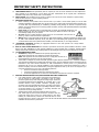
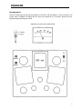
o o o o o o o o o o o o o o o o o o o o o o o o o o o o o o o o o o o o o o o o o o o o o o o o o o o o o o o o o o o o o o o o o o o o o o o o o o o o o o o o o o o o OWNER’S MANUAL o o o o o o o o o o o o o o o o o o o o o o o o o o o o o o o o o o o o o o o o o o o o o o o o o o o o o o o o o o o o o o o o o o o o o o o o o o o o o o o o o o o o CAD 300 SEI Single-ended Integrated Stereo Amplifier TABLE OF CONTENTS Important Safety Instructions ............................................................................................................. 2 Introduction .......................................................................................................................................... 4 Specifications ........................................................................................................................................ 6 Features ................................................................................................................................................ 8 Installation Unpacking ........................................................................................................................................... 9 Warranty Card...................................................................................................................................... 9 Placement ............................................................................................................................................ 9 Power Requirements ............................................................................................................................. 9 Cables ................................................................................................................................................. 9 Operation AC On Power Switch ........................................................................................................................... 10 Break-In Period .................................................................................................................................. 10 Bias Adjustment Procedures ................................................................................................................ 10 Diagrams Bias Adjustment ................................................................................................................................. 11 300B Tube ......................................................................................................................................... 12 Tube Placement Chart......................................................................................................................... 13 Service and Care Tube Replacement .............................................................................................................................. 14 Factory Service................................................................................................................................... 14 Non-Warranty Repairs......................................................................................................................... 14 Limited Warranty ................................................................................................................................ 15 IMPORTANT SAFETY INSTRUCTIONS WARNING: The triangle with the lightning flash symbol displayed on the unit advises the user of dangerous uninsulated voltage inside the product’s enclosure. CAUTION: To reduce the risk of electric shock, do not remove the cover. There are no user-serviceable parts inside; it is recommended that only qualified personnel service this component. ALERT: The triangle with the exclamation point symbol on the component suggests that the owner refer to important operating and maintenance instructions in the owner’s manual. 1. 2. 3. 4. 5. 6. 7. 8. 9. 10. 11. 12. 13. 14. OWNER’S MANUAL: Before powering up the equipment, read all safety and operating instructions and follow them as instructed. Retain the safety and operating instructions for future reference. ATTACHMENTS: Use only those attachments recommended by the unit manufacturer, as others may cause hazards. ACCESSORIES: Do not place the unit on an unstable cart, stand, tripod, bracket, or table. The unit may fall, causing injury to a person or damage to the unit. Mount the unit according to the manufacturer’s instructions with the suggested mounting accessory. WALL OR CEILING MOUNTING: Mount the unit to a wall or ceiling only in the manner recommended by the manufacturer. WATER AND MOISTURE: Do not use the unit near water (for example, near a swimming pool, bath tub, wash bowl, kitchen sink, or laundry tub) or in a damp environment (like a basement or outside in the rain). OBJECT AND LIQUID ENTRY: Do not push objects of any kind into the unit through openings as they could touch dangerous voltage points and short-out parts, possibly resulting in a fire or electric shock. Avoid spilling liquid of any kind on the unit. If water or any metal object (such as a paper clip, coin, or staple) accidentally falls inside the unit, disconnect it from the AC power source immediately and contact Cary Audio Design for further instructions. HEAT: Position the unit away from heat sources such as radiators, heat registers, stoves, or other units (including amplifiers) that produce heat. VENTILATION: Slots and openings in the cabinet create ventilation to protect the component from overheating. These openings on the top and bottom panels must remain unobstructed. Allow at least 6 inches (16cm) of clearance above the unit and an opening behind the unit for airflow. Do not place the unit on a bed, sofa, rug, built-in bookcase, or rack without adequate ventilation. GROUNDING OR POLARIZATION: As a safety feature, the unit may be equipped with a polarized alternating current line plug in which one blade is wider than the other. This plug will fit into the power outlet only one way. If you cannot insert the plug fully into the outlet, try reversing the plug. If the plug still will not fit, contact a licensed electrician to update your obsolete outlet. Do not defeat the safety purpose of the polarized plug. POWER SOURCES: Operate the unit only from the power source indicated on the marking label. If you are unsure of the type of power supplied to your home, consult your unit dealer or local power company. POWER CORD PROTECTION: Arrange power supply cords so that they do not suffer from foot traffic or pinching by items placed on or against them. Pay close attention to cords where plug enter the AC outlet and where they exit from the unit. LIGHTNING: For added protection during a lightning storm or when is the component is idle for long periods of time, unplug the unit from the wall outlet and disconnect the antenna or cable system. This will help protect the unit from lightning and power line surge damage. POWER LINES: Do not locate an outside antenna system in the vicinity of overhead power lines or other electric light or power circuits. When installing an outside antenna system, take extreme care to avoid touching the power lines or circuits; contact with them could be fatal. OVERLOADING: Do not overload wall outlets, extension cords, or integral convenience receptacles as this increases the risk of fire or electric shock. 2 IMPORTANT SAFETY INSTRUCTIONS 15. 16. 17. 18. 19. 20. 21. REPLACEMENT PARTS: When replacement parts are required, be sure the service technician has used replacement parts specified by the manufacturer or those having the same characteristics as the original parts. Unauthorized substitutions may result in fire, electric shock or other hazards. SAFETY CHECK: Upon completion of any service or repairs to the unit, ask the service technician to perform safety checks to ensure the unit is in proper operating condition. IMPORTANT SAFETY NOTE: • Before connecting a new product such as the CD 303T to your audio or home theater system, turn off all other equipment (preferably unplugging them from the AC power source). Many audio components feature automatic turnon circuits that may activate during an installation, potentially causing damage to electronic components and/or speakers. This type of damage is not covered by product warranties, and Cary Audio specifically disclaims responsibility for any such damage. • Power Cord: The removable power cord provided with your player was specifically designed for use with this product, but other AC cords may be used. Consult your dealer for advice on AC power cords and high quality wire in your system. • AC Fuse: The fuse is located inside the chassis and is not user serviceable. If the unit does not power up, contact an authorized service representative • Wiring: Cables running inside walls should have the appropriate markings to indicate compliance and listing by the UL, CSA or other standards required by the UL, CSA, NEC or your local building code. Questions about cables inside of walls should be referred to a qualified custom installer, a licensed electrician, or low-voltage contractor. RECORDING COPYRIGHT: Recording of copyrighted material for other than personal use is illegal without permission of the copyright holder. NOTE TO CATV SYSTEM INSTALLER: This reminder is provided to call the CATV system installer's attention to article 820-40 of the NEC, ANSI/NFPA 70, which provides guidelines for proper grounding and, in particular, specifies that the cable ground shall be connected to the grounding system of the building as close to the point of cable entry as practical. FCC INFORMATION FOR USER: • CAUTION: Any changes or modifications not expressly approved by Cary Audio Design could void the user's authority to operate the equipment. • NOTE: This equipment has been tested and found to comply with the limits for a Class B digital device pursuant to Part 15 of the FCC Rules. • These limits are designed to provide reasonable protection against harmful interference in a residential installation. This equipment generates and can radiate radio frequency energy, and if not installed and used in accordance with the instructions it may cause harmful interference to radio communications. However, there is no guarantee that interference will not occur in a particular installation. If this equipment does cause harmful interference to radio or television reception, which can be determined by turning the equipment off and on, the user is encouraged to try to correct the interference by one or more of the following measures: • Reorient or relocate the receiving antenna. • Increase the separation between the equipment and receiver. • Connect the equipment into an outlet on a circuit different from where the receiver is connected. OUTDOOR ANTENNA INSTALLATION/SAFE ANTENNA AND CABLE CONNECTION: • If an outside antenna or cable system is connected to the equipment, be sure the antenna or cable system is grounded in order to provide protection against built-up static charges and voltage surges. Article 810 of the National Electrical Code, ANSI/NFPA 70 (in Canada, Part 1 of the Canadian Electrical Code) provides information regarding proper grounding of the mast and supporting structure, grounding of the lead-in wire to an antenna discharge unit, size of grounding conductors, location of antenna discharge unit, connection to grounding electrodes and requirements for the grounding electrode. • Outside antenna system should be located well away from power lines, electric light or power circuits and where it will never come into contact with these power sources if it should happen to fall. When installing an outside antenna, extreme care should be taken to avoid touching power lines, circuits or other power sources as this could be fatal. Because of the hazards involved, antenna installation should be left to a professional. 3 INTRODUCTION Congratulations! You have purchased one of the most exotic vacuum tube audio integrated amplifiers available. Within its power range, the CAD 300 SEI integrated amplifier offers the most realistic sound reproduction one could desire for a “high-end” home audio system. Careful design, parts selection and proper circuit topologies contribute to the incredible reliability and enjoyment. For the technically minded, a review of the circuit is in order. Your new CAD 300 SEI operates in a class A single-ended mode utilizing an auto bias (cathode) system for the 300B triode output tubes. The input preamplifier section utilizes a 6SN7 dual triode tube. One triode section of this dual tube is used for the left channel and the other triode section is used for the right channel. This circuit is a Class A voltage gain circuit. This is the same basic first stage input circuit utilized in the Cary Audio model SLP 98 preamplifier. The next gain stage in the CAD 300 SEI utilizes a 6SN7 dual triode wired in a series constant-current plate-loaded configuration. This stage is duplicated for each channel. The series constant-current configuration then drives the 300B triode output stage in single-ended, class A. The output transformers in the CAD 300 SEI are the most important components in the amplifier and have been specifically designed by Cary Audio for use in the CAD 300 SEI. The output transformer is an airgap design with a commercial continuous rating of 200% duty cycle. The CAD 300 SEI output transformer is an E/I laminate, silicon impregnated, grain oriented steel design. The windings are wax impregnated and the entire transformer is potted in high temperature wax. Utilizing the linear, directly heated filament-cathode 300B triode output tube, there is no global feedback used in the CAD 300 SEI. The power supply is a full wave center tap configuration running high voltage, high current fast switching diode rectifiers. The rectified 450 VDC is fed to a PI-L filter network. The filter capacitor consists of two (2) 1200 MFD and 230 Joules of energy storage. Each electrolytic capacitor is by-passed with a low impedance .22 polystyrene capacitor. The power transformer is a 200% duty cycle rating on the CAD 300 SEI. To avoid AC hum, both the 6SN7 and 300B tube have DC voltage on the filaments. This will prevent AC ripple voltage from capacitively being coupled to the elements in the tubes. Additional Design Thoughts A great deal of attention during the design of your new CAD 300 SEI was concentrated on the “overload recovery” ability of the amplifier to instantly recover from clipping and is a much more important issue tan is commonly believed. In the power war of amplifier manufacturers the mentality is focused on high and then even higher power output to solve the clipping problem. When in reality, the most critical aspect is how fast a recovery an amplifier can achieve after overload. Most of the music being listened to in an average listening room is only requiring about 3 watts of power. It is on the transients of loud low frequency program material that tremendous signal voltages will appear at the input of the amplifier. It is in this situation that the overload recovery ability of an amplifier is of critical concern. The single-ended CAD 300 SEI extols its merits in the ability to handle transients and instantaneously recover from brief or even extended overloads. The CAD 300 SEI will overload symmetrically at any frequency in the audio band pass. The CAD 300 SEI will also yield faithful reproduction of extremely low frequencies at full output levels. Power transformer, power supply regulation and output transformer design and careful shaping of the overall frequency response curve all play a very important part in the ability of the CAD 300 SEI to recover quickly when overloaded. If one were to monitor the high voltage rail voltage (385 VDC at the anode of the 300B tube) of a CAD 300 SEI during soft and loud music passages it will be found there is no more than a volt or so change from soft to loud passages. Another technical feature of your new CAD 300 SEI is amplifier stability. The CAD 300 SEI may be operated with no load (without speaker) without damage to the amplifier, output transformer or tubes. This is the hallmark of a high performance, STABLE, amplifier circuit design. 4 INTRODUCTION The most exciting feature of the CAD 300 SEI, aside from how compact and gorgeous it looks, is the delightful, sensual beauty of the music it recreates. The first thing that will strike you about your CAD 300 SEI integrated amplifier is the incredible transparency and resolution of detail of the music. The CAD 300 SEI sensual nature is best revealed in the sense of life it displays in female vocalists. Your new CAD 300 SEI presents music with such presence and directness, you’ll be drawn into the music hour after musically satisfying hour. This is the result of single-ended circuit techniques, which eliminate crossover notch at low levels and also contributes to the freedom from listening fatigue. The CAD 300 SEI will draw you in even further as you realize how lucid and utterly uncolored neutrality reveals delicate nuances in the sound stage. Enjoy the music! 5 SPECIFICATIONS This section describes the basic specifications of the CAD 300 SEI at the time of printing. Specifications are subject to change without notice or obligation. When the following cautionary terms are used in this manual, these definitions apply: WARNING Electrical hazard! Misuse or failure to follow instructions properly may result in personal injury or death! CAUTION No risk or personal injury; however, misuse or failure to follow instructions may result in damage to equipment. NOTE No risk of personal injury or equipment damage; however, misuse or failure to follow instructions may prevent proper performance of the equipment. ............................................................................................................................................................ CIRCUIT TYPE Single-ended, Class A ............................................................................................................................................................ INPUTS CD, AUX 1, AUX2 ............................................................................................................................................................ POWER OUTPUT 4/8 ohms = 15 watts/CH ............................................................................................................................................................ S/N 90dB below rated power output ............................................................................................................................................................ FREQUENCY RESPONSE 23 – 20,000 Hz (+0 – 0.75dB) ............................................................................................................................................................ HEADPHONE OUTPUT 4-50 ohm compatible ¼” 3 circuit jack ............................................................................................................................................................ POWER TRANSFORMERS 1 - EI laminated, 200% duty cycle ............................................................................................................................................................ OUTPUT TRANSFORMERS 200% duty cycle Air gapped, wound with OFC copper wire, wax impregnated ............................................................................................................................................................ RESISTORS 1% metal film ............................................................................................................................................................ WIRE Silver double “E” teflon ............................................................................................................................................................ COUPLING CAPS Oil filled ............................................................................................................................................................ POWER SUPPLY CAPACITORS 2 – 1200mfd @ 450 VDC, Total – 2400 MFD – 230 Joules ............................................................................................................................................................ WIRING Point - to - point ............................................................................................................................................................ LINE INPUT 3 switchable selections ............................................................................................................................................................ SPEAKER POSTS 5-way Copper ............................................................................................................................................................ TUBE SOCKETS Ceramic with silver pins ............................................................................................................................................................ ADDITIONAL FEATURES Soft shoe feet Detachable power cord 6 SPECIFICATIONS ............................................................................................................................................................ TUBE COMPLIMENT 2 – 300B triode output tubes in Class A single-ended (CAVT 300B tubes) 1 – 6SN7 input tube 2 – 6SN7 driver tubes ............................................................................................................................................................ WARM-UP TIME 3 minutes ............................................................................................................................................................ BREAK-IN PERIOD 100 hours of music playing time ............................................................................................................................................................ FINISH Jaguar® medium blue chassis with black anodized aluminum front panel ............................................................................................................................................................ DIMENSIONS 8" H x 14" W x 14" D ............................................................................................................................................................ WEIGHT 42 lbs. ............................................................................................................................................................ 7 FEATURES Front Panel ............................................................................................................................................................ AC - ON SWITCH Turns AC power on in the “UP” position ............................................................................................................................................................ INPUT SELECTOR Selection of line inputs for listening (CD, AUX1, AUX2) ............................................................................................................................................................ VOLUME Dual precision potentiometer controlling volume of both channels ............................................................................................................................................................ BALANCE Dual precision potentiometer to balance between left and right channels ............................................................................................................................................................ HEADPHONE 3 conductor stereo headphone jack for headphones ............................................................................................................................................................ OUTPUT SELECTOR Switches amplifier output from speakers to headphones. When blue LED lights, the headphone jack is activated. (located on top right of chassis) ............................................................................................................................................................ Rear Apron ............................................................................................................................................................ INPUTS Signal input connection via shielded interconnect cables ............................................................................................................................................................ SPEAKER OUTPUT High quality 5-way binding posts provide output to the speakers ............................................................................................................................................................ POWER CORD 3 conductor shielded power cord to AC power mains ............................................................................................................................................................ FUSE AC power fuse. Never replace with any other fuse than 2 AMP SLOW BLOW! 250 VOLT ............................................................................................................................................................ TUBE FUSE Never replace with any other fuse than ¼ AMP FLAST BLOW! ............................................................................................................................................................ CAUTION EQUIPMENT DAMAGE MAY OCCUR WITH IMPROPER FUSES. NEVER REMOVE / INSERT AC LINE CORD WHEN THE UNIT IS ON. WARNING MAKE NO ATTEMPT TO PUT THE CAD 300 SEI AMPLIFIER IN SERVICE WITHOUT THE BOTTOM PLATE ATTACHED - CONTACT WITH VOLTAGE IN THE UNIT CAN BE FATAL! 8 INSTALLATION This section describes the unpacking and installation procedures for your new component. Unpacking All Cary Audio Design shipping containers have been specially designed to protect their contents and special care has been taken to prevent damage under normal shipping conditions. Mishandling should be evident upon inspection of the shipping container. If shipping damage is found after visual inspection, take care not to destroy the evidence. If necessary, document the damage with photographs and contact the transport carrier immediately. Carefully remove your new component from its packing carton and examine it closely for signs of shipping damage. We strongly recommend saving all original packing cartons to protect your amplifier from damage should you wish to store it or ship it for after-sales service. Warranty Card IN THE USA: If you are the original purchaser of a new unit from an AUTHORIZED CARY AUDIO DESIGN DEALER, please fill out the enclosed warranty registration card and return it to Cary Audio Design within 15 days of your purchase. Cary Audio Design also suggests that you keep your original packing cartons in case you ever need to ship the unit when moving to a new home. Warranty restrictions apply. Consult the warranty section at the end of this manual for details. Please be certain to keep a copy of the original sales receipt from your AUTHORIZED CARY AUDIO DESIGN DEALER to validate the warranty if ever needed. The warranty is for the original purchaser only and does not transfer to any subsequent owner. OUTSIDE THE USA: Your local Authorized Cary Audio Design Distributor will make his own warranty policy for your country. Please check with them for the terms of warranty for your new amplifier. Placement In general, the location of your new CAD 300 SEI amplifier is not critical. The best placement in your system is near the speaker system with short lengths of speaker cables. Certain precautions must be taken to ensure optimum performance. Avoid extremely hot locations such as near radiator or other heating units. Keep the top of the CAD 300 SEI clear of books, paper or other equipment to protect against overheating. Power Requirements The CAD 300 SEI is designed to operate from house current mains. The design voltage is 117 VAC at 50/60Hz. (Foreign units 220 VAC at 50/60Hz.) Cables The speaker cables from the output posts of the CAD 300 SEI to convenient length your set-up requires. Select speaker cables of outstanding performance capabilities of your CAD 300 SEI. Heavy distances up to 10 feet; #12 for 25 feet. Most audio dealers will have this purpose. the speaker system can be any sufficient size to preserve the gauge #16 wire is suitable for proper speaker cable in stock for 9 OPERATION Signal input connection is made via the input jacks on the rear of the CAD 300 SEI located next to the output binding posts. The interconnect cables from the output of the preamplifier can be any convenient length your set-up requires. The choice of a high quality interconnect cable is important. Once again, your audio dealer will have the proper cables in stock for this purpose. Your new CAD 300 SEI is ready for operation after the speaker, interconnect cables, and the tubes have been installed. Refer to the tube placement sheet at the end of this manual for proper installation. AC On Power Switch Simply push the AC rocker switch on the ON position. Observe that the blue LED lights and all tubes are lit (filaments). Break-In Period The tubes, capacitors and output transformers take approximately 100 hours of music playing to fully settle in for peak performance. The CAD 300 SEI will sound good right out of the box and will improve with use. After the first couple of hours you will notice increased depth and tighter bass. This break-in period is true with vacuum tube based audio amplifiers. Bias Adjustment Procedures Look to the left rear corner of the CAD 300 SEI. You will notice a slotted screwdriver adjustment control. This is the bias adjust potentiometer. Also located in line with this control is a ¼” headphone style jack. This will accept the included orange/black test cable. These two leads will hook to a DC current meter or digital multimeter. 1. Make sure the CAD 300 SEI is in the off position with all the tubes inserted into the proper sockets. 2. Plug in the two-conductor test cable into the ¼” jack. Clip the black alligator clip to the black negative lead on your multimeter. Hook the red alligator clip to the red positive lead from the multimeter. 3. Place the multimeter range selector in the DC current range. This may say 0 – 300 mA. Just make sure you are reading DC current. Never select the DV voltage position. Only the DC current scale. 4. Locate a proper flat blade screwdriver that fits the slot on the bias adjustment control. 5. With your CAD 300 SEI plugged into the house AC mains wall socket turn on the AC power switch. Immediately observe the DC current reading. The proper value will be 150 to 160 mA. 6. If the value is low, turn the bias control clockwise (right) a small amount. If the current reads higher than 160 mA. Turn the bias adjustment control counter clockwise (left). 7. After the 300 SEI has been on for about ten minutes recheck the bias and reset to 150 to 160 mA Range. This completes the bias setting. You may wish to check this setting every six months or so. Please note that the bias will vary as your AC line voltage moves up and down in your home. This is normal. The amplifier will operate in a broad range of 120 mA to 180 mA of current. The value of 150 to 160 is the ideal point. 8. Turn off your CAD 300 SEI and remove the test cable and store this cable in a convenient location in your listening room. WARNING MAKE SURE AMPLIFIER IS UNPLUGGED FROM AC MAINS BEFORE SERVICING. 10 DIAGRAMS Bias Adjustment Insert the meter plug into the bias jack. Adjust for 150 mA to 160 mA reading on volt ohm meter or DC current meter. Re-adjust the setting after the amp has warmed up for 10 minutes. Remove the bias adjustment plug and enjoy the music! Adjust bias pot until meter reads 160mA 11 DIAGRAMS 300B Tube 12 DIAGRAMS Tube Placement Chart CAUTION Large pins on the 300B output tubes must be inserted into the large holes in the tube socket. Failure to follow these instructions will result in serious damage to the tubes and amplifier and is not covered by the manufacturer’s warranty. 13 SERVICE AND CARE The chassis may be cleaned with a soft towel and Windex® or a similar window cleaner. Spray it on the cleaning cloth to moisten it, not on the component. Do not use solvents or harsh chemicals to clean the preamplifier. They may remove the labels from the chassis. The frequency and need of cleaning will be governed by operating environmental conditions. Avoid letting the component become dusty or wet. A ‘feather duster’ type cleaner will also work well for cleaning the component. Tube Replacement If it becomes necessary to replace the tubes in the CAD 300 SEI amplifier, a matched set of output tubes of the same brand should be used. A new tube kit is available from Cary Audio Design. You should get a few years or more from the output tubes with everyday usage and many, many years of use from the 6SN7 input tube and 6SN7 driver tubes. Factory Service Careful consideration has been given to the design of this product to keep maintenance problems to a minimum. If the problem is not easily solved, we suggest that you contact our Customer Service Department by phone at (919) 355-0010, 1–5 pm Eastern Standard Time, to describe your problem in detail. DO NOT return the component to the factory without a Return Authorization Number (RA) from the Customer Service Department. Cary Audio Design assumes no responsibility if the transportation company refuses to pay a damage claim due to your improper packing or lack of insurance should the unit be lost in shipment. We strongly suggest using the original packing cartons for shipping any Cary Audio Design component. Non-Warranty Repairs Cary Audio Design will provide repair service for its products charging on a time and expense basis. At this time, the standard non warranty service bench fee is $125 with all parts used for repair charged extra. This may change with time and is not a quote for service. Please call us at 919-355-0010 for more information about out of warranty service and repair fees. WARNINGS MAKE NO ATTEMPT TO PUT THE CAD 300 SEI IN SERVICE WITH THE BOTTOM PLATE REMOVED. CONTACT WITH HIGH VOLTAGES FOUND IN THE UNIT CAN BE FATAL. COMPLETELY REMOVE AC POWER PLUG FROM THE WALL AND ALLOW 30 MINUTES FOR THE HIGH VOLTAGE CAPACITORS TO DISCHARGE THROUGH BLEEDER RESISTORS BEFORE ATTEMPTING TO CHANGE TUBES OR CLEAN THE INSIDE OF THE AMPLIFIER. CAUTIONS NEVER REMOVE / INSERT AC PLUG WHEN THE UNIT IS ON OR THE AC POWER SWITCH IS IN THE ON POSITION. OBSTRUCTION OF THE TOP PORTION OF THE CAD 300 SEI WILL RESULT IN TUBES OVERHEATING. 14 LIMITED WARRANTY Cary Audio Warrants to the original United States purchaser for use in the United States the Following Cary Audio Products for the Periods Indicated: 1. Power Amplifiers, Integrated Amplifiers, Surround Sound Processors, and Preamplifiers have a three (3) year parts and labor warranty from the date of the original purchase from Cary Audio. 2. CD or SACD players, DVD players, or Music Servers have an eighteen (18) month parts and labor warranty from the date of the original purchase from Cary Audio. 3. Vacuum tubes, if any are used in the component, are offered a 90-day exchange policy against defects with the exception of the CAVT 300B vacuum tube that has a one (1) year exchange policy from the date of the original purchase from Cary Audio. What is Covered and What is Not Covered Except as specified below, this warranty covers parts and labor to correct all defects in materials and workmanship. The following are not covered by the warranty: 1. Damage, deterioration, malfunction or failure to meet performance specifications resulting from: a. Accident, acts of nature, misuse, abuse, neglect or unauthorized product modifications b. Improper installation, removal or maintenance, or failure to follow instructions supplied with the product. c. Repair or attempted repair by anyone not authorized by Cary Audio to repair the product. d. Any shipment of the product (claims must be presented to the carrier). e. Any cause other than a product defect. 2. Cleaning, initial set-up, check-ups with no defects found, or charges incurred for installation, removal or reinstallation of the product. 3. Any product, on which the serial number has been defaced, modified or removed. 4. Batteries. 5. Accessories, including but not limited to, batteries, cables, mounting hardware and brackets, cleaning accessories, antenna and detachable power cords. 6. Warranty is void if purchase was made from anyone other than an authorized Cary Audio dealer. Who May Enforce the Warranty? This warranty extends to products purchased directly from Cary Audio or an authorized Cary Audio dealer. Purchasers should inquire of the dealer regarding the nature and extent of the dealer’s warranty, if any. To obtain such warranty service, the original purchaser must complete and send in the Warranty Registration Card within 15 days of purchase. 15 LIMITED WARRANTY What Will We Pay For? We will pay for all labor and material expenses for items covered by the warranty. Payment of shipping charges is discussed in the next section of this warranty. How You Can Get Service? In the event that the owner needs to return the unit to Cary Audio for service or repair of a possible defect, he must follow the following steps: 1. Contact Cary Audio at 919-355-0010 to obtain a Return Merchandise Authorization (RMA) number prior to shipping; include this number with the package 2. Submit a copy of the original sales receipt; blank receipts will not validate the limited warranty for service by Cary Audio. The original sales receipt must contain the following information: a. The authorized Cary Audio dealer’s name b. The date of purchase c. The unit’s sales price d. The buyer’s name and address e. Describe in detail the problem. f. Note the unit’s model number and serial number. 3. Deliver by either of these methods: a. With all freight and insurance charges prepaid and in its original packing container or equivalent, ship the component to Cary Audio, 1020 Goodworth Drive Apex, NC 27539. b. Hand-deliver the product to Cary Audio (address noted above) or the nearest authorized service facility. Limitation of Implied Warranties All implied warranties, including warranties of merchantability and fitness for particular purchase, are limited in duration to the length of this warranty. Exclusion of Damages Cary Audio’s liability for any defective product is limited to repair or replacement of the product at Cary Audio’s option. Cary Audio shall not be liable for damage to other products caused by any defects in Cary Audio products, damages based upon inconvenience or loss of use of the product, or any other damages, whether incidental, consequential, or otherwise. 16 LIMITED WARRANTY How State Law Relates to the Warranty Some states do not allow limitations on how long an implied warranty lasts and/or do not allow the exclusion or limitation of incidental or consequential damages, so the above limitations or exclusions may not apply to you. This warranty gives you specific legal rights, and you may also have other rights which vary from state to state. International Purchasers (Export Markets) Cary Audio warrants its merchandise to purchasers within the United States exclusively for use within the United States. It provides no other warranties, expressed or implied. If you are living outside of the United States, please consult your local dealer or distributor to determine the details of your local warranty. 17 1020 Goodworth Drive, Apex, NC 27539 phone 919-355-0010 fax 919-355-0013 www.caryaudio.com o o o o o o o o o o o o o o o o o o o o o o o o o CARY AUDIO DESIGN o o o o o o o o o o o o o o o o o o o o o o o o o o o o o o o o o o o o o o o o o o o o o o o o o o o o o o o o o o o o o o o o o o o o o o o o o o o o o o o o o o o o o