1
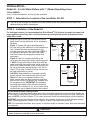
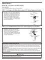
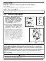
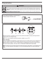
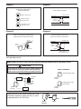
McDonnell & Miller
Installation & Maintenance
Instructions
MM-200(E)
Series 64
Low Water Cut-Off
®
Typical Applications:
- Primary or secondary low water cut-off
for hot water and steam boilers.
- Low water cut-off
- High water cut-off
- Alarm actuator
CUT-OFF
LEVEL
Model 64
CUT-OFF
LEVEL
Model 64-A
OPERATION
Maximum Boiler Pressure: 50 psi (3.5 kg/cm2)
Electrical Ratings
Voltage
120 VAC
240 VAC
Motor Switch Rating (Amperes)
Full Load
Locked Rotor
Pilot Duty
7.2
43.2
120 VA at
120
or 240 VAC
3.6
21.6
CUT-OFF
LEVEL
Model 64-CB
Model 764
NOTE: 11MV is rated 24VA @ 24VAC to 120VAC.
WARNING
ION
CAUT
ING
WARN
• Before using this product read and understand instructions.
• Save these instructions for future reference.
• All work must be performed by qualified personnel trained in the proper application, installation, and maintenance of plumbing, steam, and electrical equipment and/or systems in
accordance with all applicable codes and ordinances.
• To prevent serious burns, the boiler must be cooled to 80˚F (27˚C) and the pressure must be
0 psi (0 bar) before servicing.
• To prevent electrical shock, turn off the electrical power before making electrical connections.
• This low water cut-off must be installed in series with all other limit and operating controls
installed on the boiler. After installation, check for proper operation of all of the limit and
operating controls, before leaving the site.
• We recommend that secondary (redundant) Low Water Cut-Off controls be installed on all
steam boilers with heat input greater than 400,000 BTU/hour or operating above 15 psi of
steam pressure. At least two controls should be connected in series with the burner control
circuit to provide safety redundancy protection should the boiler experience a low water
condition. Moreover, at each annual outage, the low water cut-offs should be dismantled,
inspected, cleaned, and checked for proper calibration and performance.
• To prevent serious personal injury from steam blow down, connect a drain pipe to the control
opening to avoid exposure to steam discharge.
• To prevent a fire, do not use this low water cut-off to switch currents over 7.4A, 1/3 Hp at
120 VAC or 3.7A, 1/3 Hp at 240 VAC, unless a starter or relay is used in conjunction with it.
Failure to follow this warning could cause property damage, personal injury or death.
INSTALLATION –
Model 64 – For Steam Boilers with 1” (25mm) Equalizing Lines
TOOLS NEEDED:
One (1) flathead screwdriver and two (2) pipe wrenches.
STEP 1 - Determine the Location of the Low Water Cut-Off
a. Whether the gauge glass is mounted directly into the boiler or on an independent water column, the
cut-off line on the 64 body casting should be mounted 1/2" (15mm) above the lowest visible point of the
gauge glass.
STEP 2 - Installation of the Model 64
a. Locate the gauge glass and
determine the level that the 64
has to be mounted at in order
to achieve the criteria in Step 1.
Gauge Glass Mounted
Directly into Boiler
1" STEAM
EQUALIZING PIPE
b. Pipe the 64 following the
diagrams shown to the right.
Follow the diagram that
represents your boiler.
c. Crosses should be used at
each right angle connection for
inspection and cleaning.
d. Make sure the blow-down
valves are full port.
For Boilers with
Independent Water Columns
1" WATER
EQUALIZING PIPE
MODEL 64
LOW WATER
CUT-OFF
MODEL 64
LOW WATER
CUT-OFF
CUT-OFF
LEVEL
CUT-OFF
LEVEL
1" WATER
EQUALIZING PIPE
1" BLOW DOWN
VALVE
1" WATER
EQUALIZING PIPE
Test the Model 64 Before Leaving the Site
Open the blow-down valve, causing the water level to drop in the float chamber while burner is operating. As
the float drops the alarm circuit (if used) closes first; then on further drop the cut-off circuit will open, shutting the burner off.
IMPORTANT: Instruct boiler attendant to blow down the float chamber at least once a week during the heating
season, if operating pressure is below 15 psi (1 kg/cm2). If above 15 psi blow down once a day.
NOTE: On new boiler installations, leaky systems, or where the quality of the water is poor, blow down the
control more frequently.
CAUTION
Protect yourself when blowing down controls, hot water and steam will flow out of the drain pipe attached to the blow-down
valve. Failure to follow this caution may result in serious burns.
2
INSTALLATION –
Model 64 – For Hot Water Boilers with 1" (25mm) Equalizing Lines
TOOLS NEEDED:
One (1) flathead screwdriver and two (2) pipe wrenches.
STEP 1 - Determine the Location of the Low Water Cut-Off
a. The line on the casting of the model 64 must be installed above the lowest permissible water level
determined by the boiler manufacturer.
STEP 2 - Installation of the Model 64
For float type controls it is recommended that Test-N-Check® (TC-4) valves be used in the upper and
lower equalizing lines. They offer a functional means for testing the 64 control, and conform to the
ASME CSD-1 code.
a. Study the figures to the right and determine which
figure shows how the 64 control will be attached to
the boiler.
Figure 1. Connect the upper equalizing pipe to
the riser going to the radiation or to the compression
tank. Connect the lower equalizing pipe to any
available opening in the side of the boiler. NOTE: If
no opening is available in the side of the boiler,
connect the lower equalizing pipe into the drain
connection.
Figure 2. If there is a tapping available on the
top of the boiler connect the upper equalizing pipe to
it. NOTE: During initial filling or after blow down the
upper equalizing pipe and possibly the 64 control will
have an air pocket. Connect a vent or bleed valve on
the top of the vertical equalizing pipe. If the Test-NCheck (TC-4) valve is used the vacuum breaker can
be used to bleed the air pocket.
CAUTION: When bleeding an air pocket manually,
protect yourself from being burned with hot water.
Figure 3. If there is no tapping available on the
boiler, connect both the upper and lower equalizing
pipe into the vertical riser going to the radiation or to
the compression tank. IMPORTANT: The horizontal
equalizing pipe should not be above the horizontal
run going to the radiation. If it is, an air pocket will be
created and a vent or bleed will have to be installed.
AIR
VENT
TC-4
VERTICAL RISER TO RADIATION
OR COMPRESSION TANK
HOT WATER
BOILER
AVAILABLE OPENING
IN TOP BOILER
HOT WATER
BOILER
MODEL
64
MODEL
64
TC-4
Figure 2
Figure 1
VERTICAL RISER
TO RADIATION
MODEL
64
HOT WATER
BOILER
Figure 3
Test the Model 64 Before Leaving the Site
While the burner is operating open the blow-down valve, causing the water level to drop in the float chamber. As
the float drops the alarm circuit (if used) closes first; then on further drop the cut-off circuit will open, shutting the
burner off. NOTE: If no Test-N-Checks (TC-4) valves were used, do this test before filling the system completely.
IMPORTANT: Instruct boiler attendant to blow down the float chamber at least once a week during the heating
season, if operating pressure is below 15 psi (1 kg/cm2). If above 15 psi blow down once a day.
NOTE: On a new boiler installation, leaky system, or where the quality of the water is poor, blow down the control
more frequently.
CAUTION
Protect yourself when blowing down controls, hot water will flow out of the drain pipe attached to the blow-down valve.
Failure to follow this caution may result in serious burns.
3
INSTALLATION –
Model 764 – For Steam or Hot Water Boilers
TOOLS NEEDED:
One (1) flathead screwdriver and two (2) pipe wrenches.
STEP 1 - For Steam or Hot Water Boilers where 2 1/2” (65mm) Tapping is Provided
a. See figure 1. The 2 1/2" (65mm) tapping on
the boiler has to be above the minimum safe
operating level, as determined by the boiler
manufacturer. On steam boilers, make sure
the line on the casting is above the lower
gauge glass nut. NOTE: Do not reduce the
2 1/2" (65mm) tapping, as this would compromise low water protection.
DO NOT REDUCE
THIS 2 1/2" DIMENSION
MODEL 764
LOW WATER
CUT OFF
HOT WATER
BOILER
BLOWDOWN
VALVE
Figure 1
STEP 2 - For Hot Water Boilers where 2 1/2” (65mm) Tapping is not Provided
a. See figure 2. If there are no 2 1/2" (65mm)
tappings on a hot water boiler, the 764
control can be mounted on a 2 1/2" (65mm)
tee on the riser going to the radiation or
compression tank. NOTE: Do not reduce the
2 1/2" (65mm) tapping, as this would compromise low water protection.
DO NOT REDUCE
THIS 2 1/2" DIMENSION
MODEL 764
LOW WATER
CUT OFF
SUPPLY
LINE
HOT WATER
BOILER
BLOWDOWN
VALVE
Figure 2
Test the Model 764 Before Leaving the Site
While the burner is operating open the blow-down valve, causing the water level to drop in the float chamber.
As the float drops the alarm circuit (if used) closes first; then on further drop the cut-off circuit will open,
shutting the burner off. NOTE: If no Test-N-Checks (TC-4) valves were used, do this test before filling the
system completely.
IMPORTANT: Instruct boiler attendant to blow down the float chamber at least once a week during the heating season, if operating pressure is below 15 psi (1 kg/cm2). If above 15 psi blow down once a day.
NOTE: On a new boiler installation, leaky system, or where the quality of the water is poor, blow down the
control more frequently.
CAUTION
Protect yourself when blowing down controls, hot water will flow out of the drain pipe attached to the blow-down valve.
Failure to follow this caution may result in serious burns.
4
INSTALLATION –
Model 64-A – For Steam Boilers Using Quick Hook-up Fittings
TOOLS NEEDED:
One (1) flathead screwdriver, two (2) pipe wrenches, and an adjustable wrench.
STEP 1 - Preparing the Boiler
a. Remove gauge glass and its trim from the boiler.
STEP 2 - Installation of the Model 64-A
a. See figures 1 and 2. Install both brass Y fittings
(A) into the boiler gauge glass tappings.
NOTE: If gauge glass tappings are spaced
more than 10 1/8" (270mm) apart, invert the
Black Y (B). See figure 2. If spaced greater
than 13 3/8" (339mm), substitute a longer
1/2" (15mm) nipple for original (C).
b. See figure 3. Install reducing bushing (D) and
nipple (C) into top 1" (25mm) NPT tapping (E).
Install reducing bushing (F), nipple (G), and
blow down valve (H) into 1" (25mm) NPT (J).
INVERTED
B
A
C
Figure 2
Figure 1
P
O
c. See figure 3. Slip union nut (K) over lower tail
piece (L) and screw it into either 1/2" (15mm)
tapping (M) or (N). Use the 1/2" (15mm) pipe
plug to close unused tapping. Slip union nut (O)
over union piece (P) and nipple (R) and install
into black Y (B). Slide black Y (B) over nipple
(C). Connect upper (O) and lower (K) unions to
brass Y fitting (A, figure 1) and tighten. NOTE:
the black Y (B) will have to be moved up or
down to mate the union halves. Tighten
compression nut (S).
B
R
S
D
C
E
K
L
N
F
G
M
J
H
Figure 3
Test the Model 64-A Before Leaving the Site
While the burner is operating open the blow-down valve, causing the water level to drop in the float chamber.
As the float drops the alarm circuit (if used) closes first; then on further drop the cut-off circuit will open,
shutting the burner off. NOTE: If no Test-N-Checks (TC-4) valves were used, do this test before filling the
system completely.
IMPORTANT: Instruct boiler attendant to blow down the float chamber at least once a week during the heating season, if operating pressure is below 15 psi (1 kg/cm2). If above 15 psi blow down once a day.
NOTE: On a new boiler installation, leaky system, or where the quality of the water is poor, blow down the
control more frequently.
CAUTION
Protect yourself when blowing down controls, hot water will flow out of the drain pipe attached to the blow-down valve.
Failure to follow this caution may result in serious burns.
5
Wiring Instructions
WARNING
• To prevent electrical shock, turn off the electrical power before making electrical connections.
• This low water cut-off must be installed in series with all other limit and operating controls installed on the
boiler. After installation, check for proper operation of all of the limit and operating controls, before leaving
the site.
Failure to follow this warning could cause electrical shock, an explosion and/or a fire, which could result in
property damage, personal injury or death.
Using a flathead screwdriver, remove the one (1)
screw that secures the switch cover.
Cover
1
3
TOP
LEFT
BOTTOM
TOP
2
4
RIGHT
Electrical connector is movable into any one of four positions illustrated, by simply removing two black
headed screws and rotating housing.
NOTE: This control should be wired with materials suitable for use at 75˚C.
Switch Operation
The No. 11 switch can be identified by a black terminal panel. The switch contains two (2) single pole single throw switches to control the water feeder and the low water cut-off. The low water cut-off switch is
between terminals marked “1” and “2”. A second switch is located between terminals marked “3” and “4”.
This can be used to operate a low water alarm or a McDonnell & Miller electric water feeder.
NOTE: Connect hot wire to terminal marked (2) ahead of all controls. See diagram 1 on the following page
(page 7) for control operation. See diagrams 2-4 on the following page (page 7) for proper application
wiring.
6
Diagram 1
Diagram 2
SCHEMATIC OF TWIN SWITCH
INTERNAL OPERATION
10
30
02
4
0
USED AS MAIN LINE SWITCH
NORMAL WATER LEVEL
NEUTRAL WIRE
TO BURNER
HOT WIRE
10
30
02
10
30
02
4
0
FEEDER OR ALARM
OPERATING LEVEL
10
30
SAFETY
SWITCH
02
0
4
HOT WIRE
4
0
TO ALARM
LOW WATER CUT-OFF
OPERATING LEVEL
NEUTRAL WIRE
Diagram 3
Diagram 4
USED AS PILOT SWITCH IN SERIES WITH
HOLDING COIL OF AUTOMATIC STARTER
TO LINE
USED WITH MODEL 101 ELECTRIC
WATER VALVE OR IN ALARM CIRCUIT
L1
L2
L3
NEUTRAL WIRE
TO BURNER
HOT WIRE
SAFETY
SWITCH
SAFETY
SWITCH
10
30
02
0
4
STARTER
10
30
02
0
4
JUMPER
TO BURNER
TO
TWO WIRES OF 101A
OR TO ALARM CIRCUIT
IMPORTANT: Low water cut-off circuit of the 64 series must be electrically wired in series with all other boiler
limit operating controls.
Model 64A-M For use on 24 or 120 VAC systems requiring manual reset on low water cut-off.
CAUTION
Do not electrically connect water feeder to Model 64A-M. This
model includes a manual reset feature, failure to follow this
caution could result in boiler flooding and property damage.
SWITCH SCHEMATIC
WIRING SCHEMATIC
NEUTRAL
BURNER
1
2
3
4
RESET
BUTTON
1
2
3
4
NORMAL WATER LEVEL
RESET
BUTTON
HOT
TRANSFORMER
(OPTIONAL)
1
2
3
4
LOW WATER CUT-OFF
ALARM LEVEL
RESET
BUTTON
ALARM
Place the cover on the switch housing and, using
a flathead screwdriver, tighten the one (1) screw
to approximately 2 ft•lb (2.6 N•m).
Switch
Housing
Cover
7
McDonnell & Miller
MAINTENANCE
SCHEDULE:
• Blow down weekly during heating season.
• Open up float chamber and clean annually.
More frequent cleaning may be necessary if
there are high make-up water requirements or
poor local water quality.
• Replace control every 10 years.
TROUBLESHOOTING
Problem:
1. Burner does not shut off on low water.
a. Cause: Float chamber is loaded with mud or
sediment.
Test: With water level below the control
check if terminals 1 and 2 are open. If
not, remove switch and manually test if
terminals 1 and 2 can be opened.
Solution: Open float chamber and clean. At this
time, check for a build-up of scale or
sediment between corrugations of the
bellows.
b. Cause: Contacts are fused together.
Test: Remove switch and operate manually to
verify proper switch operation.
Solution: Replace switch. Check electrical load
and make sure it is within the ratings of
the switch.
2. Electric water feeder does not shut off.
a. Cause: Build-up of scale or sediment between
corrugations of the bellows.
Test: With water level above the control,
check if terminals 3 and 4 are open. If
not, remove switch and manually test
to verify terminals 3 and 4 can be
opened.
Solution: Open float chamber and replace or
clean the bellows.
b. Cause: Contacts are fused together.
Test: Remove switch and operate manually
to verify proper switch operation.
Solution: Replace switch. Check electrical load
and make sure it is within the ratings of
the switch.