1
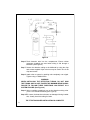
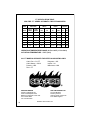
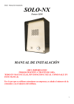
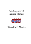
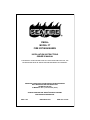
FM200®
MODEL FT
FIRE EXTINGUISHERS
INSTALLATION INSTRUCTIONS
OWNER’S MANUAL
THIS MANUAL IS AN INTEGRAL PART OF THE SYSTEM AND AS SUCH, THE
EXTINGUISHER MUST BE INSTALLED AND MAINTAINED ACCORDINGLY.
READ AND COMPLY WITH THESE INSTRUCTIONS, WARNINGS
AND LIMITATIONS BEFORE INSTALLING.
SUITABLE FOR USE
FT MODELS : 20°F (-7°C TO 130°F (54°C).
ALWAYS MAINTAIN THIS OWNER’S MANUAL NEARBY
FOR OPERATOR REFERENCE.
REV. 11/02
PRINTED IN USA
PART NO. 123-186
NOTICE
DO NOT INSTALL A FT MODEL IN LIEU OF AN APPROVED FIRE
SUPPRESSION SYSTEM.
FT MODELS ARE FOR SUPPLEMENTAL PROTECTION ONLY. FT
MODELS ARE NOT TO BE USED AS PRIMARY PROTECTION IN
MARINE ENGINE COMPARTMENTS.
WARNING
CONCENTRATED AGENT AND BY-PRODUCT OF APPLICATION TO
FIRE ARE TOXIC. AVOID BREATHING OF FUMES OR PROLONGED
EXPOSURE. ACCIDENTAL DISCHARGE MAY OCCUR DURING
HANDLING OR INSTALLATION OF THIS DEVICE, READ AND
COMPLY WITH INSTRUCTIONS, WARNINGS, AND LIMITATIONS
CONTAINED IN THIS MANUAL. DO NOT LIFT, CARRY, OR HANDLE
BY VALVE. SO NOT DROP. KEEP AWAY FROM HEAT. KEEP AWAY
FROM CHILDREN.
OWNER’S MANUAL & INSTALLATION GUIDE
SEA-FIRE FM-200® AUTOMATIC FIRE EXTINGUISHER MANUAL:
PART NO. 123-186
2
APPLICATION
FM-200® (CF3CHFCF3), the extinguishing agent, used in all Sea-Fire
“FT” series fire extinguishers, is a suitable EPA accepted alternate
replacement for Halon. FM-200® is electrically nonconductive and residue
free extinguishing agent that requires no cleanup.
These features and the versatility of design make the “FT” series fire
extinguisher ideal for a broad range of applications. These applications
would include marine, recreational vehicles, commercial and industrial
use where electrical or flammable liquids are likely source of fire. This
would include many applications such as electrical compartments, paint
and flammable storage lockers.
Sea-Fire “FT” extinguishers are designed to induce a minimum atmospheric concentration of 8.7 percent within the protected compartment.*
The specification table in this manual lists the minimum and maximum
approved compartment volume (size) allowable for each model. Volume
can be determined by multiplying the compartment’s length x width x
height which equals the volume in cubic feet or meters (LxWxH=V).
Exception: If the boat manufacturer has placed a permanently affixed
label in the compartment specifying the gross volume less the
volume of permanently installed tankage, then this volume may be used
to determine the proper size extinguisher. Check specification table for
proper application before making installation.
*Reference: NFPA-2001 National Fire Protection Assoc. Boston, MA and
UL 2166 Underwriters laboratories
CAUTION: NEVER INSTALL A UNIT WITH A VOLUME RATING LESS
THAN THE GROSS VOLUME OF THE COMPARTMENT TO BE
PROTECTED. DO NOT DEDUCT FOR ENGINES, REMOVABLE TANKS
OR OTHER EQUIPMENT.
SYSTEM OPERATIONS
Sea-Fire units described in this manual are automatically actuated by a
heat actuated tube. Discharge will occur when the tube temperature rises
to the system activation point as shown in the specification table and on
the label attached to each unit. Upon discharge, which is accompanied by
a loud report and a hissing sound, the extinguishing agent (FM-200®)
floods the compartment with an electrically nonconductive, noncorrosive
vapor that stops the combustion process through both physical and
chemical means. FM-200®, being an efficient heat transfer agent, literally
removes heat energy from the fire to the extent that the combustion reaction cannot sustain itself.
3
CAUTION: IN CASE OF EXTINGUISHER DISCHARGE, DO NOT RUSH
TO OPEN THE PROTECTED COMPARTMENT. LET THE EXTINGUISHING AGENT WORK FOR SEVERAL MINUTES. HAVE A PORTABLE
EXTINGUISHER AVAILABLE AND USE CARE WHEN OPENING THE
COMPARTMENT.
AVOID BREATHING FIRE RELATED FUMES OR VAPOR.
NOTE: It is important to retain the designed vapor concentration within
the compartment to insure complete fire outage. Upon discharge, all
powered ventilation (blowers) must be shut down.
PRESSURE SWITCH
Sea-Fire “FT” series extinguishers are equipped with a factory installed
pressure switch which is intended for cylinder pressure supervision and
may also be used to control other electrical functions (engine shutdown,
air exchange equipment, electric supply, etc.)
When using the pressure switch as an electrical disconnect for any equipment shutdown function, a means of overriding (bypassing, shunting)
the pressure switch must be provided in order to return the affected
equipment to an operational mode after extinguisher discharge has
occurred. The pressure switch is a single pole single throw (SPST) type
that is normally closed (NC) with the system in the charged condition.
Discharge or loss of system pressure will release the contacts to an open
state thereby cutting off any electrical current flow.
NEVER USE PRESSURE SWITCH FOR ELECTRICAL LOADS OVER
RATED CAPACITY.
SWITCH SPECIFICATIONS
4.0 AMPS AT 12 VDC
2.0 AMPS AT 28 VDC
For applications requiring larger load capacities, see OPTIONAL EQUIPMENT section IN THIS manual or contact factory.
GEN SETS AND POWERED VENTILATION (BLOWERS)
DIESEL ENGINES
Continued operation of diesel engine(s) and or powered ventilation units
will deplete the extinguishing agent and may cause a fire re-flash. Diesel
engine(s) must be automatically shutdown upon extinguisher
discharge.
4
Note: Power ventilation (blowers) that exceeds one air change per minute
within the protected compartment must be automatically shutdown upon
extinguisher discharge.*
*ABYC requirement - Standard A-4
GASOLINE ENGINES
Shutdown may be accomplished by interruption of the electrical circuit
between the ignition switch and the engine coils.
NOTE: Sea-Fire optional engine interrupt systems will automatically
shutdown engines and powered ventilation upon discharge of the fire
SUPPRESSION system. They are available in 12 and 24-volt models with
3, 5 or 8 control circuits. refer to OPTIONAL EQUIPMENT section in this
manual.
REMINDER: Sea-Fire systems shall be considered as supplementary to
the number of portable fire extinguishers required on-board and are
designed and intended for enclosed unoccupied compartment installations that are not subject to direct weather or water.
ELECTRIC MOTORS
In case of a fire and system discharged, the electrical supply to the motor
must be disconnected. Failure to do so may result in re-ignition after the
FM-200® concentration depletes.
Disconnect may be accomplished by using a shutdown system. See
OPTIONAL EQUIPMENT.
INSTALLATION
READ ENTIRE INSTRUCTION MANUAL AND CYLINDER NAMEPLATE
PRIOR TO INSTALLATION.
These installation instructions are intended to cover most normal installations. Additional technical or application information can be obtained by
contacting:
Sea-Fire Marine
Baltimore, Maryland, USA
Tel: 410-687-5500
or
Sea-Fire Europe LTD
Portsmouth, England
Tel: (0) 2392 462723
Website: www.sea-fire.com
5
CAUTION:
1. DO NOT INSTALL IN AN AREA DESIGNATED FOR OCCUPANCY.
2. ACCIDENTAL DISCHARGE MAY CAUSE SERIOUS INJURY.
3. HANDLE THE CYLINDER WITH EXTREME CARE.
4. WEAR EYE PROTECTION.
5. DO NOT LIFT OR CARRY CYLINDER BY THE MANIFOLD OR
ACTUATOR COMPONENTS.
6. DO NOT ATTEMPT TO LOOSEN OR REMOVE ANY EXTINGUISHER COMPONENT.
7. DO NOT ATTACH SEA-FIRE EXTINGUISHER ON UNDERSIDE OF
COVER OR COMPARTMENT HATCH THAT COULD BE THROWN
CLEAR DUE TO POSSIBLE EXPLOSION.
8. DO NOT MOUNT WHERE AN ACCUMULATION OF STANDING
WATER COULD BLOCK SENSOR OR CAUSE CORROSION.
9. EXTINGUISHER TO BE MOUNTED IN THE VERTICAL POSITION
ONLY.
10. DO NOT USE FOR PRIMARY ENGINE COMPARTMENT
PROTECTION.
EXTINGUISHER INSTALLATION:
Step 1 Carefully remove extinguisher from carton and visually check for
damage in shipment.
Step 2 To ensure that the extinguisher is operational, both the weight and
pressure indicator must conform with the extinguisher specification as shown on the nameplate. Weigh extinguisher (less bracket) on an accurate calibrated scale before installing. Record date
and weight on tag provided for this purpose.
Step 3 Choose a suitable location on the compartment bulkhead. The
location should be where accidental damage is unlikely to occur.
Step 4 Remove the extinguisher from the bracket. Using the bracket
as a template, drill (4) 1/4" diameter holes. Mount the bracket using
1
/4" hardware. (See Figure 5)
Step 5 Install the extinguisher into the bracket and latch clamp.
6
/4" (6MM)
HARDWARE
1
(Figure 5)
7
CLAMP
SUPPLIED QTY 2
GROMMET
SUPPLIED QTY 2
Figure 6
Step 6 Feed detection tube into the compartment. Ensure rubber
grommets (supplied) are used when tubing is fed through a
bulkhead. (See Figure 6)
Step 7 Secure the detection tubing to the bulkhead by using the clips
and screws supplied. Nylon wire ties may be used in lieu of the
clips and screws.
Step 8 Attach tube to system by pushing tube completely over nipple.
Tighten using a 12MM wrench.
WARNING
WHEN INSTALLING THE DETECTION TUBING, DO NOT KINK
THE TUBING AND DO NOT EXCEED THE MINIMUM BEND RADIUS.
FAILURE TO FOLLOW THESE DIRECTIONS CAN RESULT IN A
SYSTEM FAILURE. (See Figure 6)
Step 9 Using a straight screwdriver, turn on the detection tubing valve.
(Turn 1/4 turn counterclockwise) (See Figure 8)
Step 10To ensure the detection tube was not damaged during installation, visually check the tubing for leaks.
THE FT EXTINGUISHER INSTALLATION IS COMPLETE.
8
Figure 9
INDICATOR LIGHT OPERATION
All Sea-Fire extinguishers approved for marine applications are packaged
with an indicator light and escutcheon. The indicator light (unless
replaced by another Sea-Fire method) must be installed for system supervision and operator awareness. When properly installed, activation of
electrical power to the system will illuminate the light indicating normal
charged condition. System discharge or loss of pressure will immediately
extinguish the indicator light. In the event that the indicator light is not lit
when power is applied, check for the following conditions:
1.
Check pressure indicator gauge for proper range.
2.
Check fuse and indicator light and replace if defective
(lamp replacements available from factory).
3.
Check for loose electrical connections.
4.
Remove and weigh system cylinder as described in
MAINTENANCE Section of the manual.
INDICATOR LIGHT INSTALLATION
Select a location at the helm on or near the console that is in full view of
the helmsman. the location selected must have access for electrical
wiring. Remove the adhesive protective cover from back of indicator
escutcheon and attach. For proper adhesion, surface must be clean and
dry and temperature must be above 50°F (10°C). Use the preformed
9
escutcheon hole as a template and carefully drill a 5/16” (8mm) hole. Insert
indicator light wire through hole and seat light assembly by pressing clip
into position. Indicator light is now ready for wiring (see Figure 3).
CAUTION: PRIOR TO WIRING INDICATOR LIGHT, TURN OFF
ELECTRICAL POWER BY SWITCHING OFF CIRCUIT BREAKER,
REMOVING FUSE OR DISCONNECTING POSITIVE BATTERY
TERMINAL. FAILURE TO DISCONNECT ELECTRICAL POWER
WHILE MAKING ELECTRICAL CONNECTION CAN RESULT IN
INJURY FROM FIRE OR ELECTRICAL BURNS.
The indicator light is rated for 12 VDC (contact factory for other voltages).
Wire in accordance with the American Boating and Yacht Council standard E-9 “Direct current Electrical System on Boats, copies of which may
be obtained from ABYC, Edgewater, MD, USA 21037, 410-956-1050.
Supplies, which are not included with your Sea-Fire system, should be at
hand before indicator light installation, are as follows:
1.
2.
3.
4.
Five (5) ampere in-line fuse and holder
Sufficient length of insulated 16 AWG stranded wire
Crimp on wire connectors
Crimp pliers, hand tools
Attach one wire lead from the in-line fuse to the ignition position on the
starter switch. Connect other lead from the in-line fuse to the indicator
light. Connect remaining indicator lead to one of the Sea-Fire cylinder
pressure switch connector wires. Connect the remaining cylinder
pressure switch lead to common ground., which may be the negative
battery buss at the control panel, or directly to the engine block (see
Figure 3).
CAUTION: Electrical systems vary from vessel to vessel and these directions may not be applicable for your installation. Should you have any
doubts of safely accomplishing this installation, contact a qualified marine
electrician or SEA-FIRE MARINE USA at 410-687-5500 for technical
assistance.
10
SYSTEM MAINTENANCE
WARNING: DO NOT ATTEMPT TO DISASSEMBLE ANY PART OR
COMPONENT OF THE EXTINGUISHER. THIS UNIT IS PRESSURIZED
AND SERIOUS INJURY COULD RESULT. CONTACT THE FACTORY
OR AN AUTHORIZED DEALER FOR SERVICE.
Before operating, visually check to insure indicator light is operational,
and cylinder pressure indicator is in the normal range. All fire suppression
systems containing liquefied gas require periodic weighing to ensure a
fully charged unit. Pressure gauges indicate the ability to discharge the
agent, but not the quantity of extinguishing agent. The cylinder (less
bracket) must be weighed on at least a semiannual basis, and be
replaced immediately if gross weight has decreased by quantity noted on
the specification label.
Never paint or obstruct the detection tube, as this will adversely affect its
operating characteristic. FT models are non-refillable. See nameplate
on cylinder for instructions and OUT OF WARRANTY REPLACEMENTS
section of this manual.
REMINDER:
• FREQUENTLY CHECK GAUGE FOR PROPER PRESSURE
• WEIGH CYLINDER TO INSURE AMPLE EXTINGUISHER AGENT
LIMITATIONS
Sea-Fire FT model series FM-200® automatic fire extinguishers are
designed and tested to extinguish Class C (electrical) and Class B (flammable liquid) fires in enclosed compartments only. Any open doors or
hatches will allow discharging agent to escape and will seriously affect
the ability of the agent to extinguish the fire.
Only one extinguisher may be used to protect a compartment. If more
than one extinguisher is used to achieve the required amount of agent
concentration, there is no guarantee that several extinguishers will
actuate simultaneously as each extinguisher operates independently.
Several extinguishers may be used only if each independent extinguisher
is capable of protecting the entire volume of the compartment.
11
OPTIONAL EQUIPMENT
SDDA I
Panel mounted visual/audible discharge alarm unit.
ESRS-2
Panel mounted system status indicator with override switch for engine(s) restart. For use with the
ESRS engine shutdown system as a replacement
or add-on second helm station.
ESRS III, V, VIII
Engine and powered ventilation (blower) shutdown
system. Includes one circuit control unit and one
panel mounted ESRS-2 visual/audible system status indicator
with override switch for engine restart. available
with 3,5,
or 8 control circuits in 12 or 24 VDC models.
ESRS-WT III, V, VIII Same as ESRS-MARK shutdown system, but also
includes a factory-installed nominal 20-second
release timer on the engines control circuits.
For use in diesel engines that shutdown through
activation of a momentary device (i.e., push button,
lever, etc.).
SFAB12 (24)
Discharge alarm bell 6” round 12 or 24 VDC models.
ESEH-10
10 foot (3.05 meter) extender harness for use with
ESRS systems.
ESEH-30
30 foot (9.15 meter) extender harness for use with
ESRS systems.
Clean agent (FM-200®) Portable Fire extinguishers are also available.
Contact Sea-Fire or an authorized Sea-Fire dealer for details.
THREE (3) YEAR FT SERIES LIMITED WARRANTY
We warranty to the original retail purchaser all SEA-FIRE extinguishers
for a period of three (3) years after retail purchase against defective
material and faulty workmanship. any system found to be defective during
the warranty period will be repaired or replaced free of charge upon
the prepaid return of the defective system. Proof of purchase required,
otherwise date of manufacturer on extinguisher label will apply.
This warranty gives you specific legal rights which may vary by state or
country.
12
THE FOREGOING WARRANTY IS MADE IN LIEU OF ALL OTHER
WARRANTIES WITH RESPECT TO THE SYSTEM INCLUDING ANY
IMPLIED WARRANTY OF MERCHANTABILITY OR FITNESS FOR A
PARTICULAR PURPOSE. NO PERSON IS AUTHORIZED TO GIVE
ANY OTHER WARRANTY, OR TO ASSUME FOR SEA-FIRE MARINE
ANY OTHER LIABILITY IN CONNECTION WITH THE SALE OR
INSTALLATION OF ITS PRODUCTS. REPLACEMENT OF THE
SYSTEM WILL BE THE SOLE REMEDY WITH RESPECT TO ANY
LOSS OR DAMAGE TO PROPERTY. BUYER IS NOT RELYING ON
SELLER’S JUDGMENT REGARDING BUYER’S PARTICULAR
REQUIREMENTS AND BUYER HAS HAD AN OPPORTUNITY TO
INSPECT THE PRODUCT TO BUYER’S SATISFACTION.
OUT OF WARRANTY REPLACEMENTS/RECHARGES
SEA-FIRE “FT” Model Series cylinders comply with DOT Specification
39. These cylinders are not refillable. The discharged cylinder will be
replaced with comparable Sea-Fire extinguisher upon prepaid return of
the discharged system for one-half of the current suggested list price.
RETURN TO:
UNITED STATES
SEA-FIRE MARINE Division of Metalcraft Inc.
9331-A Philadelphia Road
Baltimore, Maryland 21237 USA
EUROPE
SEA-FIRE EUROPE LTD
The Teal building, Northney Marina
Hayling Island, Portsmouth
P011 ONH England
Website: www.sea-fire.com
13
FT SPECIFICATION TABLE
SEA-FIRE “FT” SERIES AUTOMATIC FIRE EXTINGUISHERS
MODEL
AREA OF
PROTECTION
DIAMETER X
HEIGHT
TUBING
SUPPLIED
IN
MM
FT
MM
2.5 x 9
64 x 229
10
3000
FM-200®
AUTO
CU.FT.
RANGE
CU.M.
RANGE
LBS
KG
25
25
.7
1.1
.5
50
50
1.4
2.2
1
3.1x 12
79 x 305
10
3000
75
75
2.1
3.3
1.5
3.1 x 15
79 x 381
10
3000
100
100
2.8
4.4
2
3.5 x 15
89 x 381
15
4500
125
125
3.5
5.5
2.5
4.1 x 16
104 x 406
15
4500
150
150
4.2
6.6
3
4.1 x 16
104 x 406
15
4500
OPERATING TEMPERATURE RANGE: 20°F to 130°F (-7°C to 54°C)
ACTUATION TEMPERATURE: 175°F (79°C)
ALL FT MODELS APPROVED FOR VERTICAL MOUNTING ONLY.
Cubic Feet = CU. FT.
Cubic Meters = CU.M.
Pounds = LBS.
Feet = FT.
SEA-FIRE MARINE
Division of Metalcraft Inc.
9331-A Philadelphia Road
Baltimore, Maryland 21237 USA
Tel: 410-687-5500
Fax: 410-687-5503
14
Kilograms = KG
Inches = IN
Millimeters = MM
SEA-FIRE EUROPE LTD
The Teal Building
Northney Marina
Hayling Island, Portsmouth
P011 ONH England
Website: www.sea-fire.com