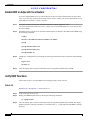
1
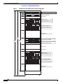
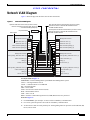
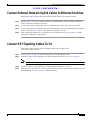
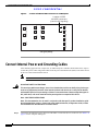
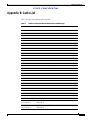
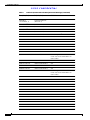
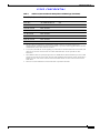
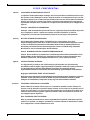
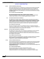
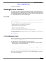
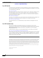
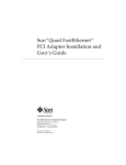
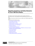
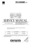
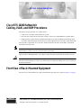
CISCO CONFIDENTIAL
Cisco BTS 10200 Softswitch
Cabling, VLAN, and IRDP Procedures
The purpose of this procedure is to explain how to:
•
Cable a new Cisco BTS 10200 Softswitch system
•
Provision the virtual local area network (VLAN) on the Cisco 2924M Ethernet Switches (hubs)
•
Enable Internet Control Protocol (ICMP) Router Discovery Protocol (IRDP) functionality on the
Cisco BTS 10200 Softswitch and on the Cisco routers adjacent to the Cisco BTS 10200 Softswitch
This procedure is applicable to a Cisco BTS 10200 Softswitch with active and standby components
colocated in the same office.
Note
This procedure is applicable only to systems with Continuous Computing hardware. If you are using
other hardware, contact your Cisco account team for procedures.
This procedure is not applicable to Cisco BTS 10200 Softswitch systems that are already in service.
Caution
Do not use this procedure to change the cabling of an in-service Cisco BTS 10200 Softswitch, because
that will cause interruption of service. It is not necessary to change the cabling of in-service systems to
match this document.
Front View of Rack-Mounted Equipment
The front view of the standard Cisco BTS 10200 Softswitch system rack is shown in Figure 1 on page 2.
Corporate Headquarters:
Cisco Systems, Inc., 170 West Tasman Drive, San Jose, CA 95134-1706 USA
Copyright © 2003. Cisco Systems, Inc. All rights reserved.
Front View of Rack-Mounted Equipment
CISCO CONFIDENTIAL
Figure 1
Standard Cisco BTS 10200 Softswitch Rack Configuration
Alarm panel, PDU power feed 8A
Filler panel
PDU (DC systems)
1U
1U
1U
2U
Filler panel
ON
APP
R
ALRM
YES
NO
OFF
CONS
EMS B (AXi)
CCN node address = 1
PDU power feed 1A/1B
PW
4U
PW
R
R
ON
APP
ALRM
OFF
CONS
YES
NO
Call agent B (AXmp)
CCN node address = 2
PDU power feed 2A/2B
6U
Filler panel
(Expansion CA or Ext. FS)
6U
2.36 m
93 in.
48U
(ref)
Ethernet switch (HUB) B (2924M)
PDU power feed 6A/6B
5U
Ethernet switch (HUB) A (2924M)
PDU power feed 7A/7B
4U
Filler panel
Filler panel
2U
ON
APP
R
ALRM
YES
NO
OFF
CONS
EMS A (AXi)
CCN node address = 3
PDU power feed 4A/4B
PW
4U
PW
R
R
ON
APP
ALRM
OFF
CONS
YES
NO
Call agent A (AXmp)
CCN node address =4
PDU power feed 5A/5B
6U
Filler panel
(Expansion CA or Ext. FS)
69411
6U
2
OL-2906-01
Network VLAN Diagram
CISCO CONFIDENTIAL
Network VLAN Diagram
Figure 2 shows the physical interfaces and VLAN connections.
Figure 2
Network VLAN Diagram
First uplink for external communications (connect to router).
Used for connection to external NEs and DNS services
via IRDP-enabled network.
Uplink for external access to hosts (connect to router).
Used for management services (SSH, SFTP, etc.)
and outbound billing data (FTP).
Physical interface
Second uplink for external communications (connect to router).
Used for connection to external NEs and DNS services
via IRDP-enabled network.
Alarm panel
Data carried
EMS/BDMS Side B
EMS/BDMS Side A
Management services HME0
HME0 Management services
OMS Hub comm. (1) QFE0
QFE0 OMS Hub comm. (1)
OMS Hub comm. (2) QFE1
QFE1 OMS Hub comm. (2)
EMS redundancy/billing (1) QFE2
QFE2 EMS redundancy/billing (1)
EMS redundancy/billing (2) QFE3
QFE3 EMS redundancy/billing (2)
CA/FS Side A
CA/FS Side B
Hub A
Management services HME0
VLAN1
HME0 Management services
VoIP signaling, OMS Hub comm. (1) QFE0
VLAN2
QFE0 VoIP signaling, OMS Hub comm. (1)
CA/FS redundancy (1) QFE1
VLAN3
QFE1 CA/FS redundancy (1)
Billing (1) QFE2
VLAN4
QFE2 Billing (1)
CA-FS comm. (1) QFE3
VLAN5
QFE3 CA-FS comm. (1)
VoIP signaling, OMS Hub comm. (2) QFE4
VLAN6
CA/FS redundancy (2) QFE5
VLAN7
QFE5 CA/FS redundancy (2)
Billing (2) QFE6
VLAN8
QFE6 Billing (2)
CA-FS comm. (2) QFE7
VLAN9
QFE7 CA-FS comm. (2)
Hub B
VoIP signaling, OMS Hub comm. (2)
87013
QFE4
Acronyms used in Figure 2:
EMS/BDMS = Element Management System/Bulk Data Management System
CA/FS = Call Agent/Feature Server
Comm. = communications over OMS Hub
NE = Network Element
SSH = Secure Shell
SFTP = Secure File Transfer Protocol (FTP)
DNS = Domain Name Server
VoIP = Voice over IP
IRDP = Internet Control Message Protocol (ICMP) Router Discovery Protocol
Notes for Figure 2:
OL-2906-01
1.
For EMS/BDMS, qfe0 and qfe1 are also used for redundancy communication.
2.
For CA/FS, qfe0 and qfe4 are also used for redundancy communication.
3.
VLAN2 and VLAN6 are used primarily for VoIP signaling based on protocols such as MGCP, SIP,
H.323, and so forth.
3
Labeling the Cables
CISCO CONFIDENTIAL
4.
Caution
If each of the three external uplinks is not connected as described in Note #4, a single point of failure
could cause a traffic interruption.
5.
Caution
Note
To support full system redundancy, it is necessary to connect each of the three
Cisco BTS 10200 Softswitch external uplinks to a different network with diverse routing paths to
the related external network elements (NEs) and services (such as OSS, DNS, media gateways, and
announcement servers).
To ensure redundancy of the DNS lookup function in the event of a network outage, it is strongly
recommended to have two DNS units reachable via separate networks with diverse routing paths.
If both DNS servers become unreachable, a traffic interruption will occur.
Ethernet ports on the rear panels of some EMS and CA units are labeled ETH0, ZNB0, ZNB1, and so
forth. On some units these ports are labeled hme0, qfe0, qfe1, and so forth. Regardless of the labeling
style, the Cisco BTS 10200 Softswitch functionality is the same.
Labeling the Cables
Make sure that you have all the cables labeled before you begin. Label the cables according to the
procedure in Appendix A: Cable Labeling, page 22.
Connect Ethernet Cables To EMS and CA Units
Follow these steps to connect the Ethernet cables. Refer to Figure 1 on page 2 to identify the specific
units in the rack.
Step 1
Obtain the 10 Ethernet cables needed for connections between the rear panel of the Element
Management Systems (EMS A and EMS B) and the two Cisco 2924M Ethernet Switches (Hub A and
Hub B). These cables are listed in Table 1 in Appendix B: Cable List, page 23.
Step 2
Connect the 10 Ethernet cables to the ports on the rear panel of the EMS units as listed in Table 1 in
Appendix B: Cable List, page 23.
Figure 3 shows the rear view of the EMS. On the EMS, use ports ETH0 and ZNB0 through ZNB3.
Note
4
Figure 3 and Figure 4 are not to scale.
OL-2906-01
Connect CONSOLE Ethernet Cables to Alarm Panel
CISCO CONFIDENTIAL
Figure 3
Partial Rear View of the EMS Unit Showing Ethernet Ports
ZNB1
ZNB0
ZNB2
ZNB3
CCPU B CCPU A
54352
ETH0
EMS (AXi)
Step 3
Obtain the 18 Ethernet cables needed for connections between the rear panel of the Call Agents (CA A
and CA B) and the two Cisco 2924M Ethernet Switches (Hub A and Hub B). These cables are listed in
Table 1 in Appendix B: Cable List, page 23.
Step 4
Connect the 18 Ethernet cables to the ports on the rear panel of the CA units as listed in Table 1 in
Appendix B: Cable List, page 23.
Figure 4 shows the rear view of the CA. On the CA, use ports ETH0 and ZNB0 through ZNB7.
Partial Rear View of the CA Unit Showing Ethernet Ports
ZNB4
ZNB6
ZNB5
ZNB7
ETH0
SPE0 SPE1 ZNB0 ZNB1 ZNB2 ZNB3
SPE2
SPE3
CCPU B CCPU A
54353
Figure 4
Call agent (AXmp)
Connect CONSOLE Ethernet Cables to Alarm Panel
Connect the two CONSOLE Ethernet cables from the Alarm Panel to the Hubs as described in this
section.
OL-2906-01
5
Connect CCPUnet Cables and Terminating Resistors
CISCO CONFIDENTIAL
Note
These two CONSOLE cables are specially designed for the CONSOLE connections. Make sure
that you are using the correct cables.
Note
One end of the CONSOLE cable is labeled “switch” and the other is labeled “net CCN”. The
“switch” end must connect to the Hub and the “net CCN” end must connect to the Alarm Panel.
Step 1
Refer to Figure 1 on page 2 to identify which Cisco 2924M Ethernet Switch (Hub) is designated
Ethernet Switch A and which is Ethernet Switch B.
Step 2
Connect the “net CCN” end of a CONSOLE cable to port SER 1 on the Alarm Panel, and the “switch”
end to the CONSOLE port on the rear panel of Ethernet switch (Hub) A.
Step 3
Connect the “net CCN” end of a CONSOLE cable to port SER 2 on the Alarm Panel, and the “switch”
end to the CONSOLE port on the rear panel of Ethernet switch (Hub) B.
The rear view of the alarm panel is shown in Figure 5. (The drawing is not to scale.)
Rear View of Alarm Panel
CCPUNet HUB A
LINE
1
2
3
4
5
6
7
1
2
3
4
5
6
7
CCPUNet HUB B
SER 1 SER 3 SER 5 SER 7 SER 9 SER 11 CONS
eth1
I/O CABLE A
SER 2 SER 4 SER 6 SER 8 SER 10 SER 12 COM1
eth0
I/O CABLE B
-48V A
-48V B
AC IN
8
8
REM
100-240 V50-60 HZ 40W
69752
Figure 5
Connect CCPUnet Cables and Terminating Resistors
Follow these steps to connect the intershelf signaling (CCPUnet) cables and terminating resistors:
Step 1
Obtain the eight CCPUnet cables (four for CCPU A and four for CCPU B).
Step 2
Connect the CCPUnet cables between the machines as listed in Table 1 on page 23. Make sure that you
connect cables labeled CCPU A to the CCPU A ports, and cables labeled CCPU B to the CCPU B
ports.
Note
Step 3
6
Refer to Figure 3 through Figure 5 to locate the CCPU ports on the rear panels.
Connect the two terminating resistors (part # CCPU 012 02150-02602 REV 00) to the Alarm Panel
(Figure 5) as follows: Connect one resistor to CCPUNet HUB A port 5, and the other resistor to
CCPUNet HUB B port 5.
OL-2906-01
Connect External Network Uplink Cables to Ethernet Switches
CISCO CONFIDENTIAL
Connect External Network Uplink Cables to Ethernet Switches
Follow these steps to connect the external network uplink cables to the Ethernet switches:
Step 1
Refer to Figure 1 on page 2 to identify which Cisco 2924M Ethernet Switch is designated Ethernet
Switch A and which is Ethernet Switch B.
Step 2
If your local network documentation calls for gigabit Ethernet, contact Cisco TAC for assistance.
Step 3
If your local network documentation calls for 100 Mb Ethernet, connect the applicable network uplink
cables as listed in Table 1. Ports #21 through 24 are available for this use.
Step 4
After installing the uplink cables, record the necessary information on a copy of Table 1 or similar
document according to local procedures.
Connect SS7 Signaling Cables To CA
Follow these steps to connect the SS7 signaling cables to the CA units of the
Cisco BTS 10200 Softswitch:
Step 1
Refer to Figure 1 on page 2 to identify which unit is CA A and which is CA B.
Step 2
Connect T1 cables for SS7 signaling to the SPE0 and SPE1 connectors on CA A (see Figure 6).
Note
OL-2906-01
SPE2 and SPE3 are not used.
Step 3
Connect T1 cables for SS7 signaling to the SPE0 and SPE1 connectors on CA B.
Step 4
Route the other ends of these T1 cables as specified in local network documentation, and add (write in)
this information on a copy of Table 1 or similar document.
7
Connect Internal Power and Grounding Cables
CISCO CONFIDENTIAL
Figure 6
Location of SPE0 and SPE1 Connectors on CA Backplane
ZNB4
ZNB6
ZNB5
ZNB7
ETH0
SPE0 SPE1 ZNB0 ZNB1 ZNB2 ZNB3
SPE2
SPE3
CCPU B CCPU A
54355
Location of SPE0
and SPE1 connectors
(Used for SS7 signaling)
Call agent (AXmp)
Connect Internal Power and Grounding Cables
After obtaining approval from a supervisor, an authorized power installer should follow these steps to
connect DC power cables and ground cables from the power distribution unit (PDU) to the other devices
in the Cisco BTS 10200 Softswitch rack.
Note
If you need to connect an AC system, contact your Cisco account team for assistance.
IMPORTANT SAFETY INSTRUCTIONS
Warning
This warning symbol means danger. You are in a situation that could cause bodily injury. Before you
work on any equipment, be aware of the hazards involved with electrical circuitry and be familiar
with standard practices for preventing accidents. To see translations of the warnings that appear in
this publication, refer to the translated safety warnings that accompanied this device.
Note: SAVE THESE INSTRUCTIONS
Note: This documentation is to be used in conjunction with the specific product installation guide
that shipped with the product. Please refer to the Installation Guide, Configuration Guide, or other
enclosed additional documentation for further details.
Step 1
8
Connect the intershelf DC power cables from the PDU to each of the devices in the rack. See Table 1 on
page 23 for the complete cabling list.
OL-2906-01
Connect Site Power and Grounding Cables To PDU
CISCO CONFIDENTIAL
Step 2
Warning
Following local electrical codes, connect the ground cables from each of the devices in the rack to the
PDU grounding point (either of the two grounding screws on the PDU rear panel). See Table 1 for the
complete cabling list.
This equipment must be grounded. Never defeat the ground conductor or operate the equipment in
the absence of a suitably installed ground conductor. Contact the appropriate electrical inspection
authority or an electrician if you are uncertain that suitable grounding is available.
Connect Site Power and Grounding Cables To PDU
After obtaining approval from a supervisor, an authorized power installer should follow these steps to
connect the DC power from the office batteries to the PDU.
Note
For DC systems the nominal current rating for a complete Cisco BTS 10200 Softswitch system
is 26A at -48 VDC, and the maximum current rating is 40A at -48 VDC.
Note
If you need to connect an AC system, contact your Cisco account team for assistance.
IMPORTANT SAFETY INSTRUCTIONS
Warning
This warning symbol means danger. You are in a situation that could cause bodily injury. Before you
work on any equipment, be aware of the hazards involved with electrical circuitry and be familiar
with standard practices for preventing accidents. To see translations of the warnings that appear in
this publication, refer to the translated safety warnings that accompanied this device.
Note: SAVE THESE INSTRUCTIONS
Note: This documentation is to be used in conjunction with the specific product installation guide
that shipped with the product. Please refer to the Installation Guide, Configuration Guide, or other
enclosed additional documentation for further details.
OL-2906-01
Step 1
Following local electrical codes, connect power cables from the power distribution unit (PDU) to dual
feeds (“A” and “B”) on the office batteries. Use Listed two-hole crimped lugs on the PDU side of the
cable.
Step 2
Following local electrical codes, connect the PDU grounding point (both of the two grounding screws
on the PDU rear panel) to CO earth ground using 6 AWG wire or heavier and a Listed two-hole crimped
lug.
9
Connect Site Power and Grounding Cables To PDU
CISCO CONFIDENTIAL
Warning
10
This equipment must be grounded. Never defeat the ground conductor or operate the equipment in
the absence of a suitably installed ground conductor. Contact the appropriate electrical inspection
authority or an electrician if you are uncertain that suitable grounding is available.
OL-2906-01
Provision VLANs
CISCO CONFIDENTIAL
Provision VLANs
Follow the procedures in this section to provision the VLANs on the Cisco 2924M Ethernet Switches
(Hubs). You will need to enter a password to log on to these hubs.
Provision VLANs On Hub A
Follow these steps to provision the VLANs on the Cisco 2924M Ethernet Switch A (Hub A):
Step 1
Connect a console cable to the Hub A console port. Use Figure 1 on page 2 to help identify which
machine is designated as Hub A.
Step 2
Switch> Enter: enable
Step 3
The system will prompt you for a password. Enter the password.
Step 4
Switch# Enter: config t
The system will respond with the following prompt: Switch (config)#
Note
Step 5
Tip
Copy the entire config text and paste at the Switch (config)# prompt.
If you are viewing a pdf file, you can get an electronic copy of this config text using the following
method: Select the “Text Select Tool” (the large “T” in the Adobe Acrobat toolbar above this file). Select
all the config text on this page (Acrobat allows you to copy from only one page at a time.) Use the
Edit/Copy feature (or right click) to get an electronic copy. Paste into a text document. Repeat on the
following pages until you have all the necessary text in your text file. Copy all the text in your text file,
and paste it into your XTerm window.
The config text (for Step 5) is as follows. See the Tips paragraph above for assistance with copying:
hostname switch-a
!
interface FastEthernet0/1
description 120-Network Name-Redundancy1
switchport access vlan 146
!
interface FastEthernet0/2
description 120-Network Name-Redundancy1
switchport access vlan 146
!
interface FastEthernet0/3
description 120-Network Name-Redundancy1
switchport access vlan 146
OL-2906-01
11
Provision VLANs
CISCO CONFIDENTIAL
!
interface FastEthernet0/4
description 120-Network Name-Redundancy1
switchport access vlan 146
!
interface FastEthernet0/5
description 122-Network Name-Billing1
switchport access vlan 147
!
interface FastEthernet0/6
description 122-Network Name-Billing1
switchport access vlan 147
!
interface FastEthernet0/7
description 122-Network Name-Billing1
switchport access vlan 147
!
interface FastEthernet0/8
description 122-Network Name-Billing1
switchport access vlan 147
!
interface FastEthernet0/9
description 124-Network Name-FeatureServer1
switchport access vlan 148
!
interface FastEthernet0/10
description 124-Network Name-FeatureServer1
switchport access vlan 148
!
interface FastEthernet0/11
description 225-Network Name-MGCP1
switchport access vlan 149
!
interface FastEthernet0/12
description 225-Network Name-MGCP1
switchport access vlan 149
!
interface FastEthernet0/13
12
OL-2906-01
Provision VLANs
CISCO CONFIDENTIAL
description 225-Network Name-MGCP1
switchport access vlan 149
!
interface FastEthernet0/14
description 225-Network Name-MGCP1
switchport access vlan 149
!
interface FastEthernet0/15
description 225-Network Name-MGCP1
switchport access vlan 149
!
interface FastEthernet0/16
description 224-Network Name-Telnet
switchport access vlan 150
!
interface FastEthernet0/17
description 224-Network Name-Telnet
switchport access vlan 150
!
interface FastEthernet0/18
description 224-Network Name-Telnet
switchport access vlan 150
!
interface FastEthernet0/19
description 224-Network Name-Telnet
switchport access vlan 150
!
interface FastEthernet0/20
description 224-Network Name-Telnet
switchport access vlan 150
!
interface FastEthernet0/21
description 224-Network Name-Telnet
switchport access vlan 150
!
interface FastEthernet0/22
description 224-Network Name-Telnet
switchport access vlan 150
OL-2906-01
13
Provision VLANs
CISCO CONFIDENTIAL
!
interface FastEthernet0/23
description 224-Network Name-Telnet
switchport access vlan 150
!
interface FastEthernet0/24
Step 6
Add the VLANs to the database using the following commands:
switch-a#vlan database
switch-a(vlan)#vlan 146
switch-a(vlan)#vlan 147
switch-a(vlan)#vlan 148
switch-a(vlan)#vlan 149
switch-a(vlan)#vlan 150
switch-a(vlan)#exit
Step 7
After the system exits, write the changes to memory using the following command:
write mem
Step 8
Display the VLAN status using the show vlan command at the Enter prompt:
sh vlan
Step 9
Verify that the status display includes response lines exactly as shown in the following system
response:
switch-a#show vlan
VLAN Name
Status
Ports
---- -------------------------------- --------- ------------------------------1
default
Fa0/24
146 VLAN0146
active
Fa0/1, Fa0/2, Fa0/3, Fa0/4
147 VLAN0147
active
Fa0/5, Fa0/6, Fa0/7, Fa0/8
148 VLAN0148
active
Fa0/9, Fa0/10
149 VLAN0149
active
Fa0/11, Fa0/12, Fa0/13, Fa0/14, Fa0/15
150 VLAN0150
active
Fa0/16, Fa0/17, Fa0/18, Fa0/19, Fa0/20, Fa0/21, Fa0/22, Fa0/23
Note
14
active
Ignore the additional lines of information displayed.
OL-2906-01
Provision VLANs
CISCO CONFIDENTIAL
Provision VLANs On Hub B
Follow these steps to provision the VLANs on Cisco 2924M Ethernet Switch B (Hub B):
Step 1
Connect a console cable to the Hub B console port. Use Figure 1 on page 2 to help identify which
machine is designated as Hub B.
Step 2
Switch> Enter: enable
Step 3
The system will prompt you for a password. Enter the password.
Step 4
Switch# Enter: config t
The system will respond with the following prompt: Switch (config)#
Note
Step 5
Tip
Copy the entire config text and paste at the Switch (config)# prompt.
If you are viewing a pdf file, you can get an electronic copy of this config text using the following
method: Select the “Text Select Tool” (the large “T” in the Adobe Acrobat toolbar above this file). Select
all the config text on this page (Acrobat allows you to copy from only one page at a time.) Use the
Edit/Copy feature (or right click) to get an electronic copy. Paste into a text document. Repeat on the
following pages until you have all the necessary text in your text file. Copy all the text in your text file,
and paste it into your XTerm window.
The config text (for Step 5) is as follows. See the Tips paragraph above for assistance with copying:
hostname switch-b
!
interface FastEthernet0/1
description 121-Network Name-Redundancy2
switchport access vlan 146
!
interface FastEthernet0/2
description 121-Network Name-Redundancy2
switchport access vlan 146
!
interface FastEthernet0/3
description 121-Network Name-Redundancy2
switchport access vlan 146
!
interface FastEthernet0/4
description 121-Network Name-Redundancy2
switchport access vlan 146
!
OL-2906-01
15
Provision VLANs
CISCO CONFIDENTIAL
interface FastEthernet0/5
description 123-Network Name-Billing2
switchport access vlan 147
!
interface FastEthernet0/6
description 123-Network Name-Billing2
switchport access vlan 147
!
interface FastEthernet0/7
description 123-Network Name-Billing2
switchport access vlan 147
!
interface FastEthernet0/8
description 123-Network Name-Billing2
switchport access vlan 147
!
interface FastEthernet0/9
description 124-Network Name-FeatureServer2
switchport access vlan 148
!
interface FastEthernet0/10
description 124-Network Name-FeatureServer2
switchport access vlan 148
!
interface FastEthernet0/11
description 226-Network Name-MGCP2
switchport access vlan 149
!
interface FastEthernet0/12
description 226-Network Name-MGCP2
switchport access vlan 149
!
interface FastEthernet0/13
description 226-Network Name-MGCP2
switchport access vlan 149
!
interface FastEthernet0/14
description 226-Network Name-MGCP2
16
OL-2906-01
Provision VLANs
CISCO CONFIDENTIAL
switchport access vlan 149
!
interface FastEthernet0/15
description 226-Network Name-MGCP2
switchport access vlan 149
!
interface FastEthernet0/16
!
interface FastEthernet0/17
!
interface FastEthernet0/18
!
interface FastEthernet0/19
!
interface FastEthernet0/20
!
interface FastEthernet0/21
!
interface FastEthernet0/22
!
interface FastEthernet0/23
!
interface FastEthernet0/24
Step 6
Add the VLANs to the database using the following commands:
switch-b#vlan database
switch-b(vlan)#vlan 146
switch-b(vlan)#vlan 147
switch-b(vlan)#vlan 148
switch-b(vlan)#vlan 149
switch-b(vlan)#exit
Step 7
After the system exits, write the changes to memory using the following command:
write mem
Step 8
Display the VLAN status using the show vlan command at the Enter prompt:
sh vlan
OL-2906-01
17
Provision VLANs
CISCO CONFIDENTIAL
Step 9
Verify that the status display includes response lines exactly as shown in the following system
response:
switch-b#show vlan
VLAN Name
Status
Ports
---- -------------------------------- --------- ------------------------------1
default
active
Fa0/16, Fa0/17, Fa0/18, Fa0/19, Fa0/20, Fa0/21, Fa0/22, Fa0/23,
Fa0/24
146 VLAN0146
active
Fa0/1, Fa0/2, Fa0/3, Fa0/4
147 VLAN0147
active
Fa0/5, Fa0/6, Fa0/7, Fa0/8
148 VLAN0148
active
Fa0/9, Fa0/10
149 VLAN0149
active
Fa0/11, Fa0/12, Fa0/13, Fa0/14, Fa0/15
Note
18
Ignore the additional lines of information displayed.
OL-2906-01
Enable IRDP
CISCO CONFIDENTIAL
Enable IRDP
This section discusses how to enable IRDP functionality on the Cisco BTS 10200 Softswitch and on the
network router.
Enable IRDP on the Cisco BTS 10200 Softswitch
Follow these steps to enable IRDP on the Cisco BTS 10200 Softswitch.
Note
You should already have the Cisco BTS 10200 Softswitch application software installed on the
system.
Step 1
Remove the defaultrouter file from /etc.
Step 2
There should be three default routes in the routing table. Remove all three of these with the following
command:
route delete net default <gateway address>
Step 3
Execute the following command:
/usr/sbin/in.rdisc -s -f
Step 4
Note
Step 5
Edit S69inet and search and replace for rdisc -s with rdisc -s -f.
This will ensure that reboot will enable the irdp daemon.
Put the following lines into the S68inet file:
if [ -f /usr/sbin/in.routed ];
then
\mv -f /usr/sbin/in.routed /usr/sbin/in.routed.org
OL-2906-01
19
Enable IRDP
CISCO CONFIDENTIAL
Enable IRDP on Adjacent Cisco Routers
If you are enabling IRDP on Cisco routers adjacent to the Cisco BTS 10200 Softswitch, follow these
steps. If you have any questions about setup of these routers, contact your system administrator. If you
need additional assistance, contact Cisco TAC.
Step 1
Verify that you have the network information data sheet (NIDS) applicable to this
Cisco BTS 10200 Softswitch. If necessary, contact your network administrator to verify that you have
the correct NIDS.
Step 2
On default gateway interfaces for Network2 and Network3 (as defined in the NIDS) enable IRDP using
the following commands:
config t
interface <Fast Ethernet interface number (see NIDS)>
ip irdp
ip irdp maxadvertinterval 4
ip irdp minadvertinterval 3
ip irdp holdtime 10
Step 3
Validate the configuration by performing the following command on both CA/FS hosts and both EMS
hosts:
login as root
#netstat -rn
Step 4
View the display and verify that each default route was populated dynamically by IRDP.
Verify IRDP Functions
Follow these steps to verify that IRDP is functioning properly on the network:
Side A CA
Perform Step 1 through Step 11 on the side A CA.
Step 1
Login to the side A CA as root.
Step 2
Display the IRDP daemon status by entering the following command:
ps -ef|grep in.rdisc
Step 3
20
View the display and verify that each default route was populated dynamically by IRDP. The display
should include the following information: /usr/sbin/in.rdisc -s -f. (This indicates that IRDP is running
properly.)
OL-2906-01
Verify Interfaces
CISCO CONFIDENTIAL
Step 4
Display the routing table by entering the following command:
netstat -rn
Step 5
Verify that the routing table shows two default routes, one on interface ZNB0 and one on ZNB4.
Step 6
Unplug the interface ZNB0 link at the back of the side A CA.
Step 7
Display the routing table by entering the following command:
netstat -rn
Step 8
Verify that the route for interface ZNB0 does not appear in the routing table.
Note
When a link is unplugged or plugged back in, it may take 5 to 10 seconds for the IRDP function
to automatically update.
Step 9
Plug the interface ZNB0 link back in to the side A CA.
Step 10
Display the routing table (netstat -rn) and verify that the route for interface ZNB0 appears in the
routing table again.
Step 11
Repeat Step 6 through Step 10 for the interface ZNB4 link.
Side B CA
Repeat Step 1 through Step 11 for the side B CA.
Verify Interfaces
Follow these steps to verify that all interfaces are configured on all computing elements:
Step 1
If the Cisco BTS 10200 Softswitch application software has already been installed on the system, go to
Step 2. If the application has not been installed, go to Step 4.
Step 2
(If the Cisco BTS 10200 Softswitch application software has already been installed on the system)
check the interface configurations using the following command on each of the four platforms (two
EMS units and two CA/FS units):
Enter: checkCFG
Step 3
The system should display the message Validating..... If no errors are found during validation, the
system will display the message No errors found. Verify that the No errors found message is displayed.
Note
Step 4
OL-2906-01
If the system does display an error, contact Cisco TAC for assistance.
If the Cisco BTS 10200 Softswitch application software has not been installed on the system, install the
application using the Application Installation procedure provided by Cisco. That procedure contains
the appropriate commands to check the configurations (checkCFG).
21
Appendix A: Cable Labeling
CISCO CONFIDENTIAL
Appendix A: Cable Labeling
Cables are labeled at both ends with the cable numbers listed in Table 1. Follow these steps to create and
attach the labels.
Note
As listed in Table 1, some of the cables require labeling and others do not.
Step 1
Make each label by copying the applicable number from Table 1 onto the label. Be sure to duplicate the
number several times onto the label, as shown in Figure 7, to make it easier to read. (If desired, make
the labels for all cables in one print run.)
Step 2
On a work bench or assembly table, position a cable so that one connector is on your left and the cable
goes off to the right. (See Figure 7.)
Step 3
Attach the appropriate label to the cable as shown in Figure 7.
Step 4
Turn the cable around so that the other connector is on your left with the cable going off to the right.
Step 5
Repeat Step 2 and Step 3 for this side of the cable. The completed cable should look like the example
shown in Figure 8.
Step 6
Repeat these steps for all cables in the rack, using the numbers from the cable list (Table 1).
Labeling Specification
#16
#16
#16
#16
#16
Surface of connector that is flush
with rear panel when installed.
Cable
#16
#16
#16
Label (example)
to match cable list
1 inch
Completed Cable Example
#16
#16
#16
22
#16
#16
#16
Figure 8
54358
Connector
Multiple rows on label, sufficient
to ensure that label can be read
without need to rotate or twist cable.
54357
Figure 7
OL-2906-01
Appendix B: Cable List
CISCO CONFIDENTIAL
Appendix B: Cable List
Table 1 lists the cable numbers and connections.
Table 1
OL-2906-01
Cable List (See Procedure for Descriptions and Drawings)
From (Unit, Port)
To (Unit, Port)
Cable No.
CA-A ETH0
HUB-A 16
#1
CA-A ZNB0
HUB-A 11
#2
CA-A ZNB1
HUB-A 1
#3
CA-A ZNB2
HUB-A 5
#4
CA-A ZNB3
HUB-A 9
#5
CA-A ZNB4
HUB-B 11
#6
CA-A ZNB5
HUB-B 1
#7
CA-A ZNB6
HUB-B 5
#8
CA-A ZNB7
HUB-B 9
#9
CA-B ETH0
HUB-A 17
#10
CA-B ZNB0
HUB-A 12
#11
CA-B ZNB1
HUB-A 2
#12
CA-B ZNB2
HUB-A 6
#13
CA-B ZNB3
HUB-A 10
#14
CA-B ZNB4
HUB-B 12
#15
CA-B ZNB5
HUB-B 2
#16
CA-B ZNB6
HUB-B 6
#17
CA-B ZNB7
HUB-B 10
#18
EMS-A ETH0
HUB-A 18
#19
EMS-A ZNB0
HUB-A 13
#20
EMS-A ZNB1
HUB-B 13
#21
EMS-A ZNB2
HUB-A 7
#22
EMS-A ZNB3
HUB-B 7
#23
EMS-B ETH0
HUB-A 19
#24
EMS-B ZNB0
HUB-A 14
#25
EMS-B ZNB1
HUB-B 14
#26
EMS-B ZNB2
HUB-A 8
#27
EMS-B ZNB3
HUB-B 8
#28
1
HUB-A 21
(see footnote 1)
Uplink for Telnet
(Network 1)
HUB-A 15
(see footnote 1)
Uplink for MGCP1 1
(Network 2)
23
Appendix B: Cable List
CISCO CONFIDENTIAL
Table 1
Cable List (See Procedure for Descriptions and Drawings) (continued)
From (Unit, Port)
To (Unit, Port)
HUB-B 15
(see footnote 1)
Uplink for MGCP2 1
(Network 3)
CA-A SPE02
(see footnote 2)
CA-A SPE12
(see footnote 2)
CA-B SPE0
2
(see footnote 2)
CA-B SPE1
2
(see footnote 2)
Alarm SER 1
HUB-A CONSOLE
CONSOLE cable3
Alarm SER 2
HUB-B CONSOLE
CONSOLE cable3
Alarm eth0
HUB-A 20
#29
not used
24
Cable No.
#30
CA-A CCPU A
Alarm CCPUNet A-1
#31
EMS-A CCPU A
Alarm CCPUNet A-2
#32
CA-B CCPU A
Alarm CCPUNet A-3
#33
EMS-B CCPU A
Alarm CCPUNet A-4
#34
n/a
Alarm CCPUNet A-5
Terminating Resistor
CCPU 012 02150-02602 REV 00
(not a cable)
CA-A CCPU B
Alarm CCPUNet B-1
#35
EMS-A CCPU B
Alarm CCPUNet B-2
#36
CA-B CCPU B
Alarm CCPUNet B-3
#37
EMS-B CCPU B
Alarm CCPUNet B-4
#38
n/a
Alarm CCPUNet B-5
Terminating Resistor
CCPU 012 02150-02602 REV 00
(not a cable)
PDU-A-1
EMS-B DC-A
#51
PDU-A-2
CA-B DC-A
#52
PDU-A-4
EMS-A DC-A
#54
PDU-A-5
CA-A DC-A
#55
PDU-A-6
HUB-B DC-A
#56
PDU-A-7
HUB-A DC-A
#57
PDU-A-8
ALARM PANEL-A
#58 4
PDU-B-1
EMS-B DC-B
#61
PDU-B-2
CA-B DC-B
#62
PDU-B-4
EMS-A DC-B
#64
PDU-B-5
CA-A DC-B
#65
PDU-B-6
HUB-B DC-B
#66
PDU-B-7
HUB-A DC-B
#67
OL-2906-01
Appendix B: Cable List
CISCO CONFIDENTIAL
Table 1
Cable List (See Procedure for Descriptions and Drawings) (continued)
From (Unit, Port)
To (Unit, Port)
Cable No.
PDU-B-8
ALARM PANEL-B
#58 4
HUB-A Ground
PDU Ground
HUB-B Ground
PDU Ground
CA-A Ground
PDU Ground
CA-B Ground
PDU Ground
EMS-A Ground
PDU Ground
EMS-B Ground
PDU Ground
Alarm Panel Ground
PDU Ground
1. The ports shown are applicable to 100 Mb Ethernet uplinks. Cable No. for uplink connections are
customer-defined. See the procedure for more information. If you need to connect gigabit Ethernet instead of
100Mb Ethernet, contact Cisco TAC for assistance.
2. To (Unit, Port) and Cable No. for SS7 signaling (T1) connections are customer-defined. In some networks, SS7
cables do not need to be connected to the Cisco BTS 10200 Softswitch. See the procedure for more
information.
3. The CONSOLE cables are specially designed for Cisco 2924M Ethernet Switch CONSOLE port access. Make
sure that you are using the correct cables. One end of the CONSOLE cable is labeled “switch” and the other is
labeled “net CCN”. The “switch” end must connect to the Hub and the “net CCN” end must connect to the
Alarm Panel.
4. There are two cables labeled #58. Connect both cables as specified in this table.
OL-2906-01
25
Appendix C: Translated Safety Warnings
CISCO CONFIDENTIAL
Appendix C: Translated Safety Warnings
Warning Definition
IMPORTANT SAFETY INSTRUCTIONS
Warning
This warning symbol means danger. You are in a situation that could cause bodily injury. Before you
work on any equipment, be aware of the hazards involved with electrical circuitry and be familiar
with standard practices for preventing accidents. To see translations of the warnings that appear in
this publication, refer to the translated safety warnings that accompanied this device.
Note: SAVE THESE INSTRUCTIONS
Note: This documentation is to be used in conjunction with the specific product installation guide
that shipped with the product. Please refer to the Installation Guide, Configuration Guide, or other
enclosed additional documentation for further details.
Waarschuwing
BELANGRIJKE VEILIGHEIDSINSTRUCTIES
Dit waarschuwingssymbool betekent gevaar. U verkeert in een situatie die lichamelijk letsel kan
veroorzaken. Voordat u aan enige apparatuur gaat werken, dient u zich bewust te zijn van de bij
elektrische schakelingen betrokken risico's en dient u op de hoogte te zijn van de standaard
praktijken om ongelukken te voorkomen. Voor een vertaling van de waarschuwingen die in deze
publicatie verschijnen, dient u de vertaalde veiligheidswaarschuwingen te raadplegen die bij dit
apparaat worden geleverd.
Opmerking BEWAAR DEZE INSTRUCTIES.
Opmerking Deze documentatie dient gebruikt te worden in combinatie met de
installatiehandleiding voor het specifieke product die bij het product wordt geleverd. Raadpleeg de
installatiehandleiding, configuratiehandleiding of andere verdere ingesloten documentatie voor
meer informatie.
Varoitus
TÄRKEITÄ TURVALLISUUTEEN LIITTYVIÄ OHJEITA
Tämä varoitusmerkki merkitsee vaaraa. Olet tilanteessa, joka voi johtaa ruumiinvammaan. Ennen
kuin työskentelet minkään laitteiston parissa, ota selvää sähkökytkentöihin liittyvistä vaaroista ja
tavanomaisista onnettomuuksien ehkäisykeinoista. Tässä asiakirjassa esitettyjen varoitusten
käännökset löydät laitteen mukana toimitetuista ohjeista.
Huomautus SÄILYTÄ NÄMÄ OHJEET
Huomautus Tämä asiakirja on tarkoitettu käytettäväksi yhdessä tuotteen mukana tulleen
asennusoppaan kanssa. Katso lisätietoja asennusoppaasta, kokoonpano-oppaasta ja muista
mukana toimitetuista asiakirjoista.
26
OL-2906-01
Appendix C: Translated Safety Warnings
CISCO CONFIDENTIAL
Attention
IMPORTANTES INFORMATIONS DE SÉCURITÉ
Ce symbole d'avertissement indique un danger. Vous vous trouvez dans une situation pouvant causer
des blessures ou des dommages corporels. Avant de travailler sur un équipement, soyez conscient
des dangers posés par les circuits électriques et familiarisez-vous avec les procédures couramment
utilisées pour éviter les accidents. Pour prendre connaissance des traductions d'avertissements
figurant dans cette publication, consultez les consignes de sécurité traduites qui accompagnent cet
appareil.
Remarque CONSERVEZ CES INFORMATIONS
Remarque Cette documentation doit être utilisée avec le guide spécifique d'installation du produit
qui accompagne ce dernier. Veuillez vous reporter au Guide d'installation, au Guide de
configuration, ou à toute autre documentation jointe pour de plus amples renseignements.
Warnung
WICHTIGE SICHERHEITSANWEISUNGEN
Dieses Warnsymbol bedeutet Gefahr. Sie befinden sich in einer Situation, die zu einer
Körperverletzung führen könnte. Bevor Sie mit der Arbeit an irgendeinem Gerät beginnen, seien Sie
sich der mit elektrischen Stromkreisen verbundenen Gefahren und der Standardpraktiken zur
Vermeidung von Unfällen bewusst. Übersetzungen der in dieser Veröffentlichung enthaltenen
Warnhinweise sind im Lieferumfang des Geräts enthalten.
Hinweis BEWAHREN SIE DIESE SICHERHEITSANWEISUNGEN AUF
Hinweis Dieses Handbuch ist zum Gebrauch in Verbindung mit dem Installationshandbuch für Ihr
Gerät bestimmt, das dem Gerät beiliegt. Entnehmen Sie bitte alle weiteren Informationen dem
Handbuch (Installations- oder Konfigurationshandbuch o. Ä.) für Ihr spezifisches Gerät.
Figyelem!
FONTOS BIZTONSÁGI ELÕÍRÁSOK
Ez a figyelmezetõ jel veszélyre utal. Sérülésveszélyt rejtõ helyzetben van. Mielõtt bármely
berendezésen munkát végezte, legyen figyelemmel az elektromos áramkörök okozta kockázatokra,
és ismerkedjen meg a szokásos balesetvédelmi eljárásokkal. A kiadványban szereplõ
figyelmeztetések fordítása a készülékhez mellékelt biztonsági figyelmeztetések között található.
Megjegyzés ÕRIZZE MEG EZEKET AZ UTASÍTÁSOKAT!
Megjegyzés Ezt a dokumentációt a készülékhez mellékelt üzembe helyezési útmutatóval együtt kell
használni. További tudnivalók a mellékelt Üzembe helyezési útmutatóban (Installation Guide),
Konfigurációs útmutatóban (Configuration Guide) vagy más dokumentumban találhatók.
Avvertenza
IMPORTANTI ISTRUZIONI SULLA SICUREZZA
Questo simbolo di avvertenza indica un pericolo. La situazione potrebbe causare infortuni alle
persone. Prima di intervenire su qualsiasi apparecchiatura, occorre essere al corrente dei pericoli
relativi ai circuiti elettrici e conoscere le procedure standard per la prevenzione di incidenti. Per le
traduzioni delle avvertenze riportate in questo documento, vedere le avvertenze di sicurezza che
accompagnano questo dispositivo.
Nota CONSERVARE QUESTE ISTRUZIONI
Nota La presente documentazione va usata congiuntamente alla guida di installazione specifica
spedita con il prodotto. Per maggiori informazioni, consultare la Guida all'installazione, la Guida
alla configurazione o altra documentazione acclusa.
OL-2906-01
27
Appendix C: Translated Safety Warnings
CISCO CONFIDENTIAL
Advarsel
VIKTIGE SIKKERHETSINSTRUKSJONER
Dette varselssymbolet betyr fare. Du befinner deg i en situasjon som kan forårsake personskade.
Før du utfører arbeid med utstyret, bør du være oppmerksom på farene som er forbundet med
elektriske kretssystemer, og du bør være kjent med vanlig praksis for å unngå ulykker. For å se
oversettelser av advarslene i denne publikasjonen, se de oversatte sikkerhetsvarslene som følger
med denne enheten.
Merk TA VARE PÅ DISSE INSTRUKSJONENE
Merk Denne dokumentasjonen skal brukes i forbindelse med den spesifikke
installasjonsveiledningen som fulgte med produktet. Vennligst se installasjonsveiledningen,
konfigureringsveiledningen eller annen vedlagt tilleggsdokumentasjon for detaljer.
Aviso
INSTRUÇÕES IMPORTANTES DE SEGURANÇA
Este símbolo de aviso significa perigo. O utilizador encontra-se numa situação que poderá ser
causadora de lesões corporais. Antes de iniciar a utilização de qualquer equipamento, tenha em
atenção os perigos envolvidos no manuseamento de circuitos eléctricos e familiarize-se com as
práticas habituais de prevenção de acidentes. Para ver traduções dos avisos incluídos nesta
publicação, consulte os avisos de segurança traduzidos que acompanham este dispositivo.
Nota GUARDE ESTAS INSTRUÇÕES
Nota Esta documentação destina-se a ser utilizada em conjunto com o manual de instalação
incluído com o produto específico. Consulte o manual de instalação, o manual de configuração ou
outra documentação adicional inclusa, para obter mais informações.
¡Advertencia!
INSTRUCCIONES IMPORTANTES DE SEGURIDAD
Este símbolo de aviso indica peligro. Existe riesgo para su integridad física. Antes de manipular
cualquier equipo, considere los riesgos de la corriente eléctrica y familiarícese con los
procedimientos estándar de prevención de accidentes. Vea las traducciones de las advertencias
que acompañan a este dispositivo.
Nota GUARDE ESTAS INSTRUCCIONES
Nota Esta documentación está pensada para ser utilizada con la guía de instalación del producto
que lo acompaña. Si necesita más detalles, consulte la Guía de instalación, la Guía de
configuración o cualquier documentación adicional adjunta.
Varning!
VIKTIGA SÄKERHETSANVISNINGAR
Denna varningssignal signalerar fara. Du befinner dig i en situation som kan leda till personskada.
Innan du utför arbete på någon utrustning måste du vara medveten om farorna med elkretsar och
känna till vanliga förfaranden för att förebygga olyckor. Se översättningarna av de
varningsmeddelanden som finns i denna publikation, och se de översatta säkerhetsvarningarna som
medföljer denna anordning.
OBS! SPARA DESSA ANVISNINGAR
OBS! Denna dokumentation ska användas i samband med den specifika
produktinstallationshandbok som medföljde produkten. Se installationshandboken,
konfigurationshandboken eller annan bifogad ytterligare dokumentation för närmare detaljer.
28
OL-2906-01
Appendix C: Translated Safety Warnings
CISCO CONFIDENTIAL
OL-2906-01
29
Appendix C: Translated Safety Warnings
CISCO CONFIDENTIAL
Ground Conductor Warning
Warning
Waarschuwing
This equipment must be grounded. Never defeat the ground conductor or operate the equipment in
the absence of a suitably installed ground conductor. Contact the appropriate electrical inspection
authority or an electrician if you are uncertain that suitable grounding is available.
Deze apparatuur dient geaard te zijn. De aardingsleiding mag nooit buiten werking worden gesteld
en de apparatuur mag nooit bediend worden zonder dat er een op de juiste wijze geïnstalleerde
aardingsleiding aanwezig is. Neem contact op met de bevoegde instantie voor elektrische
inspecties of met een elektricien als u er niet zeker van bent dat er voor passende aarding
gezorgd is.
Varoitus
Laitteiden on oltava maadoitettuja. Älä koskaan ohita maajohdinta tai käytä laitteita ilman oikein
asennettua maajohdinta. Ota yhteys sähkötarkastusviranomaiseen tai sähköasentajaan, jos olet
epävarma maadoituksen sopivuudesta.
Attention
Cet équipement doit être mis à la masse. Ne jamais rendre inopérant le conducteur de masse ni
utiliser l'équipement sans un conducteur de masse adéquatement installé. En cas de doute sur la
mise à la masse appropriée disponible, s'adresser à l'organisme responsable de la sécurité
électrique ou à un électricien.
Warnung
Dieses Gerät muss geerdet sein. Auf keinen Fall den Erdungsleiter unwirksam machen oder das
Gerät ohne einen sachgerecht installierten Erdungsleiter verwenden. Wenn Sie sich nicht sicher
sind, ob eine sachgerechte Erdung vorhanden ist, wenden Sie sich an die zuständige
Inspektionsbehörde oder einen Elektriker.
Figyelem!
A berendezés csak megfelelõ védõföldeléssel mûködtethetõ. Ne iktassa ki a földelés csatlakozóját,
és ne üzemeltesse a berendezést szabályosan felszerelt földelõ vezeték nélkül! Ha nem biztos
benne, hogy megfelelõ földelés áll rendelkezésbe, forduljon a helyi elektromos hatóságokhoz vagy
egy villanyszerelõhöz.
Avvertenza
Questa apparecchiatura deve essere dotata di messa a terra. Non escludere mai il conduttore di
protezione né usare l'apparecchiatura in assenza di un conduttore di protezione installato in modo
corretto. Se non si è certi della disponibilità di un adeguato collegamento di messa a terra,
richiedere un controllo elettrico presso le autorità competenti o rivolgersi a un elettricista.
Advarsel
Dette utstyret må jordes. Omgå aldri jordingslederen og bruk aldri utstyret uten riktig montert
jordingsleder. Ta kontakt med fagfolk innen elektrisk inspeksjon eller med en elektriker hvis du er
usikker på om det finnes velegnet jordning.
Aviso
Este equipamento deve ser aterrado. Nunca anule o fio terra nem opere o equipamento sem um
aterramento adequadamente instalado. Em caso de dúvida com relação ao sistema de aterramento
disponível, entre em contato com os serviços locais de inspeção elétrica ou um eletricista
qualificado.
¡Advertencia!
Este equipo debe estar conectado a tierra. No inhabilite el conductor de tierra ni haga funcionar el
equipo si no hay un conductor de tierra instalado correctamente. Póngase en contacto con la
autoridad correspondiente de inspección eléctrica o con un electricista si no está seguro de que
haya una conexión a tierra adecuada.
30
OL-2906-01
Appendix C: Translated Safety Warnings
CISCO CONFIDENTIAL
Varning!
OL-2906-01
Denna utrustning måste jordas. Koppla aldrig från jordledningen och använd aldrig utrustningen
utan en på lämpligt sätt installerad jordledning. Om det föreligger osäkerhet huruvida lämplig
jordning finns skall elektrisk besiktningsauktoritet eller elektriker kontaktas.
31
Obtaining Documentation
CISCO CONFIDENTIAL
Obtaining Documentation
These sections explain how to obtain documentation from Cisco Systems.
World Wide Web
You can access the most current Cisco documentation on the World Wide Web at this URL:
http://www.cisco.com
Translated documentation is available at this URL:
http://www.cisco.com/public/countries_languages.shtml
Documentation CD-ROM
Cisco documentation and additional literature are available in a Cisco Documentation CD-ROM
package, which is shipped with your product. The Documentation CD-ROM is updated monthly and may
be more current than printed documentation. The CD-ROM package is available as a single unit or
through an annual subscription.
Ordering Documentation
You can order Cisco documentation in these ways:
•
Registered Cisco.com users (Cisco direct customers) can order Cisco product documentation from
the Networking Products MarketPlace:
http://www.cisco.com/cgi-bin/order/order_root.pl
•
Registered Cisco.com users can order the Documentation CD-ROM through the online Subscription
Store:
http://www.cisco.com/go/subscription
•
Nonregistered Cisco.com users can order documentation through a local account representative by
calling Cisco Systems Corporate Headquarters (California, U.S.A.) at 408 526-7208 or, elsewhere
in North America, by calling 800 553-NETS (6387).
Documentation Feedback
You can submit comments electronically on Cisco.com. In the Cisco Documentation home page, click
the Fax or Email option in the “Leave Feedback” section at the bottom of the page.
You can e-mail your comments to [email protected].
You can submit your comments by mail by using the response card behind the front cover of your
document or by writing to the following address:
Cisco Systems
Attn: Document Resource Connection
170 West Tasman Drive
San Jose, CA 95134-9883
32
OL-2906-01
Obtaining Technical Assistance
CISCO CONFIDENTIAL
We appreciate your comments.
Obtaining Technical Assistance
Cisco provides Cisco.com as a starting point for all technical assistance. Customers and partners can
obtain online documentation, troubleshooting tips, and sample configurations from online tools by using
the Cisco Technical Assistance Center (TAC) Web Site. Cisco.com registered users have complete access
to the technical support resources on the Cisco TAC Web Site.
Cisco.com
Cisco.com is the foundation of a suite of interactive, networked services that provides immediate, open
access to Cisco information, networking solutions, services, programs, and resources at any time, from
anywhere in the world.
Cisco.com is a highly integrated Internet application and a powerful, easy-to-use tool that provides a
broad range of features and services to help you with these tasks:
•
Streamline business processes and improve productivity
•
Resolve technical issues with online support
•
Download and test software packages
•
Order Cisco learning materials and merchandise
•
Register for online skill assessment, training, and certification programs
If you want to obtain customized information and service, you can self-register on Cisco.com. To access
Cisco.com, go to this URL:
http://www.cisco.com
Technical Assistance Center
The Cisco Technical Assistance Center (TAC) is available to all customers who need technical assistance
with a Cisco product, technology, or solution. Two levels of support are available: the Cisco TAC
Web Site and the Cisco TAC Escalation Center.
Cisco TAC inquiries are categorized according to the urgency of the issue:
•
Priority level 4 (P4)—You need information or assistance concerning Cisco product capabilities,
product installation, or basic product configuration.
•
Priority level 3 (P3)—Your network performance is degraded. Network functionality is noticeably
impaired, but most business operations continue.
•
Priority level 2 (P2)—Your production network is severely degraded, affecting significant aspects
of business operations. No workaround is available.
•
Priority level 1 (P1)—Your production network is down, and a critical impact to business operations
will occur if service is not restored quickly. No workaround is available.
The Cisco TAC resource that you choose is based on the priority of the problem and the conditions of
service contracts, when applicable.
OL-2906-01
33
Obtaining Technical Assistance
CISCO CONFIDENTIAL
Cisco TAC Web Site
You can use the Cisco TAC Web Site to resolve P3 and P4 issues yourself, saving both cost and time.
The site provides around-the-clock access to online tools, knowledge bases, and software. To access the
Cisco TAC Web Site, go to this URL:
http://www.cisco.com/tac
All customers, partners, and resellers who have a valid Cisco service contract have complete access to
the technical support resources on the Cisco TAC Web Site. The Cisco TAC Web Site requires a
Cisco.com login ID and password. If you have a valid service contract but do not have a login ID or
password, go to this URL to register:
http://www.cisco.com/register/
If you are a Cisco.com registered user, and you cannot resolve your technical issues by using the Cisco
TAC Web Site, you can open a case online by using the TAC Case Open tool at this URL:
http://www.cisco.com/tac/caseopen
If you have Internet access, we recommend that you open P3 and P4 cases through the Cisco TAC
Web Site.
Cisco TAC Escalation Center
The Cisco TAC Escalation Center addresses priority level 1 or priority level 2 issues. These
classifications are assigned when severe network degradation significantly impacts business operations.
When you contact the TAC Escalation Center with a P1 or P2 problem, a Cisco TAC engineer
automatically opens a case.
To obtain a directory of toll-free Cisco TAC telephone numbers for your country, go to this URL:
http://www.cisco.com/warp/public/687/Directory/DirTAC.shtml
Before calling, please check with your network operations center to determine the level of Cisco support
services to which your company is entitled: for example, SMARTnet, SMARTnet Onsite, or Network
Supported Accounts (NSA). When you call the center, please have available your service agreement
number and your product serial number.
CCIP, CCSP, the Cisco Arrow logo, the Cisco Powered Network mark, the Cisco Systems Verified logo, Cisco Unity, Follow Me Browsing, FormShare,
iQ Net Readiness Scorecard, Networking Academy, and ScriptShare are trademarks of Cisco Systems, Inc.; Changing the Way We Work, Live, Play, and
Learn, The Fastest Way to Increase Your Internet Quotient, and iQuick Study are service marks of Cisco Systems, Inc.; and Aironet, ASIST, BPX,
Catalyst, CCDA, CCDP, CCIE, CCNA, CCNP, Cisco, the Cisco Certified Internetwork Expert logo, Cisco IOS, the Cisco IOS logo, Cisco Press, Cisco
Systems, Cisco Systems Capital, the Cisco Systems logo, Empowering the Internet Generation, Enterprise/Solver, EtherChannel, EtherSwitch, Fast Step,
GigaStack, Internet Quotient, IOS, IP/TV, iQ Expertise, the iQ logo, LightStream, MGX, MICA, the Networkers logo, Network Registrar, Packet, PIX,
Post-Routing, Pre-Routing, RateMUX, Registrar, SlideCast, SMARTnet, StrataView Plus, Stratm, SwitchProbe, TeleRouter, TransPath, and VCO are
registered trademarks of Cisco Systems, Inc. and/or its affiliates in the U.S. and certain other countries.
All other trademarks mentioned in this document or Web site are the property of their respective owners. The use of the word partner does not imply a
partnership relationship between Cisco and any other company. (0303R)
Copyright © 2003 Cisco Systems, Inc.
All rights reserved.
34
OL-2906-01