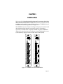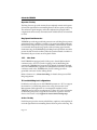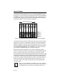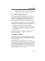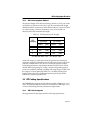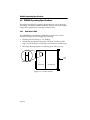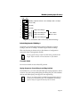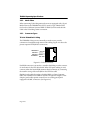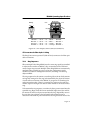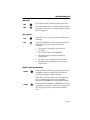
1
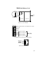
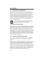
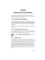
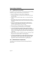
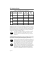
TDRMIM-22A/42ATM TOKEN RING DUAL REPEATER MIM USER’S GUIDE TDRMIM Quick Reference Card SW1 Front Panel Switchblock SW1 Motherboard Daughterboard Side View of the TDRMIM OFF Fiber Optic Keying Sequence 8 8 7 7 6 6 [Unused] 5 5 [Unused] 4 4 [Leave OFF] 3 3 FNB Ring 1 Speed Default: ON = 16 Mbps; OFF = 4 Mbps 2 2 1 1 ON Ring Ports 1 Ring In Ring Ports 1 Ring Out Ring Ports 2 Ring In ON = 802.5 OFF = ctron Ring Ports 2 Ring Out Switchblock SW1 with Factory Default Settings TRANSMIT + RECEIVE RECEIVE + TRANSMIT - 8 7 6 5 4 3 2 1 RJ45 Lobe Port Pinouts QR-1 ALL LED SIGNALS Normal operation ERR ERR R Hardware error condition, or reset in process BYP G Module Bypass—No ports inserted in FNB rings FNB interfaces active BYP G MGMT Hardware defaults in effect MGMT Y 16 MB G IN USE Ring inactive (no lobes connected) G 12 G Port enabled and transmitting Port linked but disabled by management Port in standby state 12 12 Ring active Ring active but bypassed from FNB G IN USE 12 16 Mbps ring speed in effect 4 Mbps ring speed in effect 16 MB IN USE Management control in effect (hardware default switches overridden) R Speed Fault on linked port 12 R Port disabled and not linked PEN G Ring Port set enabled Ring Port set disabled PEN LNK G Ring Port set linked Ring Port set disabled, or autowrapped, or not linked LNK LEGEND: G = GREEN R = RED QR-2 Y = YELLOW = off G = Blinking GREEN R = Blinking RED NOTICE NOTICE 1 Cabletron Systems reserves the right to make changes in specifications and other information contained in this document without prior notice. The reader should in all cases consult Cabletron Systems to determine whether any such changes have been made. The hardware, firmware, or software described in this manual is subject to change without notice. IN NO EVENT SHALL CABLETRON SYSTEMS BE LIABLE FOR ANY INCIDENTAL, INDIRECT, SPECIAL, OR CONSEQUENTIAL DAMAGES WHATSOEVER (INCLUDING BUT NOT LIMITED TO LOST PROFITS) ARISING OUT OF OR RELATED TO THIS MANUAL OR THE INFORMATION CONTAINED IN IT, EVEN IF CABLETRON SYSTEMS HAS BEEN ADVISED OF, KNOWN, OR SHOULD HAVE KNOWN, THE POSSIBILITY OF SUCH DAMAGES. Copyright July, 1995 by: Cabletron Systems, Inc. P.O. Box 5005, Rochester, NH 03866-0505 All Rights Reserved. Printed in the United States of America. Order Number 9031428 July, 1995. FNB, MMAC, TRXMIM, TRBMIM, TDRMIM, TRMIM, TRMM-2, and TRMM4 are trademarks of Cabletron Systems, Inc. Flexible Network Bus, Multi Media Access Center, SPECTRUM, LANVIEW, and Remote LANVIEW are registered trademarks of Cabletron Systems, Inc. IBM is a registered trademark of International Business Machines Corporation. DEC and VT100 are trademarks of Digital Equipment Corporation. CompuServe is a registered trademark of CompuServe, Inc. Printed on Recycled Paper i NOTICE FCC NOTICE 2 This device complies with Part 15 of the FCC rules. Operation is subject to the following two conditions: (1) this device may not cause harmful interference, and (2) this device must accept any interference received, including interference that may cause undesired operation. NOTE: This equipment has been tested and found to comply with the limits for a Class A digital device, pursuant to Part 15 of the FCC rules. These limits are designed to provide reasonable protection against harmful interference when the equipment is operated in a commercial environment. This equipment uses, generates, and can radiate radio frequency energy and if not installed in accordance with the operator’s manual, may cause harmful interference to radio communications. Operation of this equipment in a residential area is likely to cause interference in which case the user will be required to correct the interference at his own expense. WARNING: Changes or modifications made to this device which are not expressly approved by the party responsible for compliance could void the user’s authority to operate the equipment. DOC NOTICE 3 This digital apparatus does not exceed the Class A limits for radio noise emissions from digital apparatus set out in the Radio Interference Regulations of the Canadian Department of Communications. Le présent appareil numérique n’émet pas de bruits radioélectriques dépassant les limites applicables aux appareils numériques de la class A prescrites dans le Règlement sur le brouillage radioélectrique édicté par le ministère des Communications du Canada. CABLETRON SYSTEMS, INC. PROGRAM LICENSE AGREEMENT 4 IMPORTANT: Before using this product, carefully read this License Agreement. This document is an agreement between you, the end user, and Cabletron Systems, Inc. (“Cabletron”) that sets forth your rights and obligations with respect to the Cabletron software program (the “Program”) contained in this package. The Program may be contained in firmware, chips or other media. BY UTILIZING THE ENCLOSED PRODUCT, YOU ARE AGREEING TO BECOME BOUND BY THE TERMS OF THIS AGREEMENT, WHICH INCLUDES THE LICENSE AND THE LIMITATION OF WARRANTY AND DISCLAIMER OF LIABILITY. IF YOU DO NOT AGREE TO THE TERMS OF THIS AGREEMENT, PROMPTLY RETURN THE UNUSED PRODUCT TO THE PLACE OF PURCHASE FOR A FULL REFUND. ii NOTICE CABLETRON SOFTWARE PROGRAM LICENSE 1. 5 LICENSE. You have the right to use only the one (1) copy of the Program provided in this package subject to the terms and conditions of this License Agreement. You may not copy, reproduce or transmit any part of the Program except as permitted by the Copyright Act of the United States or as authorized in writing by Cabletron. 2. OTHER RESTRICTIONS. You may not reverse engineer, decompile, or disassemble the Program. 3. APPLICABLE LAW. This License Agreement shall be interpreted and governed under the laws and in the state and federal courts of New Hampshire. You accept the personal jurisdiction and venue of the New Hampshire courts. EXCLUSION OF WARRANTY AND DISCLAIMER OF LIABILITY 1. 6 EXCLUSION OF WARRANTY. Except as may be specifically provided by Cabletron in writing, Cabletron makes no warranty, expressed or implied, concerning the Program (including Its documentation and media). CABLETRON DISCLAIMS ALL WARRANTIES, OTHER THAN THOSE SUPPLIED TO YOU BY CABLETRON IN WRITING, EITHER EXPRESS OR IMPLIED, INCLUDING BUT NOT LIMITED TO IMPLIED WARRANTIES OF MERCHANTABLITY AND FITNESS FOR A PARTICULAR PURPOSE, WITH RESPECT TO THE PROGRAM, THE ACCOMPANYING WRITTEN MATERIALS, AND ANY ACCOMPANYING HARDWARE. 2. NO LIABILITY FOR CONSEQUENTIAL DAMAGES. IN NO EVENT SHALL CABLETRON OR ITS SUPPLIERS BE LIABLE FOR ANY DAMAGES WHATSOEVER (INCLUDING, WITHOUT LIMITATION, DAMAGES FOR LOSS OF BUSINESS, PROFITS, BUSINESS INTERRUPTION, LOSS OF BUSINESS INFORMATION, SPECIAL, INCIDENTAL, CONSEQUENTIAL, OR RELIANCE DAMAGES, OR OTHER LOSS) ARISING OUT OF THE USE OR INABILITY TO USE THIS CABLETRON PRODUCT, EVEN IF CABLETRON HAS BEEN ADVISED OF THE POSSIBILITY OF SUCH DAMAGES. BECAUSE SOME STATES DO NOT ALLOW THE EXCLUSION OR LIMITATION OF LIABILITY FOR CONSEQUENTIAL OR INCIDENTAL DAMAGES, OR ON THE DURATION OR LIMITATION OF IMPLIED WARRANTEES IN SOME INSTANCES THE ABOVE LIMITATIONS AND EXCLUSIONS MAY NOT APPLY TO YOU. iii NOTICE UNITED STATES GOVERNMENT RESTRICTED RIGHTS 7 The enclosed product (a) was developed solely at private expense; (b) contains “restricted computer software” submitted with restricted rights in accordance with Section 52227-19 (a) through (d) of the Commercial Computer Software Restricted Rights Clause and its successors, and (c) in all respects is proprietary data belonging to Cabletron and/or its suppliers. For Department of Defense units, the product is licensed with “Restricted Rights” as defined in the DoD Supplement to the Federal Acquisition Regulations, Section 52.227-7013 (c) (1) (ii) and its successors, and use, duplication, disclosure by the Government is subject to restrictions as set forth in subparagraph (c) (1) (ii) of the Rights in Technical Data and Computer Software clause at 252.227-7013. Cabletron Systems, Inc., 35 Industrial Way. Rochester, New Hampshire 03866 iv CONTENTS CHAPTER 1 1.1 1.2 1.3 Using This Manual . . . . . . . . . . . . . . . . . . . . . . . . . . . . . . . 1-2 About the TDRMIM . . . . . . . . . . . . . . . . . . . . . . . . . . . . . . 1-2 1.2.1 Ring In/Ring Out Ports . . . . . . . . . . . . . . . . . . . . . . 1-3 1.2.2 Lobe Ports . . . . . . . . . . . . . . . . . . . . . . . . . . . . . . . . 1-4 1.2.3 Cluster Switching . . . . . . . . . . . . . . . . . . . . . . . . . . 1-5 1.2.4 Automatic Configuration at Power-Up. . . . . . . . . . 1-7 1.2.5 Support for Passive MAU Workgroups . . . . . . . . . 1-8 1.2.6 Interaction with Other MIMs in the MMAC . . . . . 1-8 1.2.7 LANVIEW LEDs . . . . . . . . . . . . . . . . . . . . . . . . . 1-10 1.2.8 Network Management. . . . . . . . . . . . . . . . . . . . . . 1-10 Supplemental Information . . . . . . . . . . . . . . . . . . . . . . . . 1-10 1.3.1 Related Manuals . . . . . . . . . . . . . . . . . . . . . . . . . . 1-10 1.3.2 Recommended Reading . . . . . . . . . . . . . . . . . . . . 1-10 1.3.3 Getting Help . . . . . . . . . . . . . . . . . . . . . . . . . . . . . 1-11 CHAPTER 2 2.1 2.2 2.3 2.4 2.5 Introduction Requirements and Specifications General Cabling Considerations . . . . . . . . . . . . . . . . . . . . . 2-1 2.1.1 Maximum Number of Stations on a Ring . . . . . . . . 2-1 2.1.2 Crosstalk and Noise . . . . . . . . . . . . . . . . . . . . . . . . 2-1 2.1.3 Installation Recommendations . . . . . . . . . . . . . . . . 2-2 2.1.4 Network Performance Requirements . . . . . . . . . . . 2-2 UTP Cabling Specifications . . . . . . . . . . . . . . . . . . . . . . . . 2-3 2.2.1 UTP Cable Categories. . . . . . . . . . . . . . . . . . . . . . . 2-3 2.2.2 UTP Cable Lengths to Stations. . . . . . . . . . . . . . . . 2-5 STP Cabling Specifications . . . . . . . . . . . . . . . . . . . . . . . . 2-5 2.3.1 STP Cable Categories . . . . . . . . . . . . . . . . . . . . . . . 2-5 2.3.2 STP Cable Lengths to Stations . . . . . . . . . . . . . . . . 2-6 Fiber Optic Cable Specifications . . . . . . . . . . . . . . . . . . . . 2-7 TDRMIM Operating Specifications . . . . . . . . . . . . . . . . . . 2-8 2.5.1 Switchblock SW1 . . . . . . . . . . . . . . . . . . . . . . . . . . 2-8 2.5.2 Media Filters . . . . . . . . . . . . . . . . . . . . . . . . . . . . . 2-10 2.5.3 Connector Types . . . . . . . . . . . . . . . . . . . . . . . . . . 2-10 2.5.4 Ring Sequence . . . . . . . . . . . . . . . . . . . . . . . . . . . 2-11 v CONTENTS 2.6 2.5.5 LANVIEW LEDs . . . . . . . . . . . . . . . . . . . . . . . . . 2-12 Other Specifications . . . . . . . . . . . . . . . . . . . . . . . . . . . . . 2-12 2.6.1 Hardware Specifications . . . . . . . . . . . . . . . . . . . . 2-12 2.6.2 Environmental Requirements . . . . . . . . . . . . . . . . 2-12 2.6.3 Safety Issues . . . . . . . . . . . . . . . . . . . . . . . . . . . . . 2-12 2.6.4 Service. . . . . . . . . . . . . . . . . . . . . . . . . . . . . . . . . . 2-13 CHAPTER 3 3.1 3.2 General Considerations. . . . . . . . . . . . . . . . . . . . . . . . . . . . 3-1 Installation. . . . . . . . . . . . . . . . . . . . . . . . . . . . . . . . . . . . . . 3-1 3.2.1 Unpacking the TDRMIM . . . . . . . . . . . . . . . . . . . . 3-2 3.2.2 Setting Configuration Switches . . . . . . . . . . . . . . . 3-2 3.2.3 Installing the TDRMIM into an MMAC . . . . . . . . 3-2 3.2.4 Boot-Up Check . . . . . . . . . . . . . . . . . . . . . . . . . . . . 3-3 3.2.5 Connecting Twisted Pair Cabling . . . . . . . . . . . . . . 3-4 3.2.6 Connecting Ring In/Ring Out Cables . . . . . . . . . . . 3-7 3.2.7 Pre-Operational Testing . . . . . . . . . . . . . . . . . . . . . 3-7 CHAPTER 4 4.1 4.2 vi Testing and Troubleshooting Installation Checkout . . . . . . . . . . . . . . . . . . . . . . . . . . . . . 4-1 LANVIEW LED Signals . . . . . . . . . . . . . . . . . . . . . . . . . . 4-2 APPENDIX A A.1 A.2 A.3 A.4 A.5 Installation Introduction to Port Switching Introduction. . . . . . . . . . . . . . . . . . . . . . . . . . . . . . . . . . . . The Flexible Network Bus (FNB). . . . . . . . . . . . . . . . . . . Without Port Switching. . . . . . . . . . . . . . . . . . . . . . . . . . . With Port Switching . . . . . . . . . . . . . . . . . . . . . . . . . . . . . Configuration Specifications . . . . . . . . . . . . . . . . . . . . . . A-1 A-1 A-1 A-2 A-5 CHAPTER 1 Introduction Welcome to the Token Ring Dual Port Repeater/Concentrator Switching Media Interface Module User’s Guide. This manual is a reference for the installation and troubleshooting of Cabletron Systems’ TDRMIM-22A and TDRMIM-42A modules, represented in Figure 1-1. The TDRMIM is an active cluster-switching twisted pair concentrator with dual multimode fiber Ring In/Out repeater ports for Token Ring expansions. The IEEE 802.5 compliant and IBM compatible TDRMIM is designed for installation into any Cabletron Systems Multi Media Access Center (MMAC) equipped with a Flexible Network Bus (FNB). TDRMIM-22A SN 1 2 3 4 5 6 RING 1 RING 2 RING 3 RING 4 AUX 1 AUX 2 7 8 9 10 11 12 BYP 16Mb 16Mb 16Mb 16Mb 16Mb 16Mb SN 1 2 3 4 5 6 1 x LNK 2 x PEN TX RI 3 x R I N G 4 x P O R T S LNK 5 x TDRMIM-42A ERR MGMT IN USE IN USE IN USE IN USE IN USE IN USE RX PEN 1 RING 1 RING 2 RING 3 RING 4 AUX 1 AUX 2 7 8 9 10 11 12 BYP 16Mb 16Mb 16Mb 16Mb 16Mb 16Mb 1 x LNK 2 x TX 3 x 4 x P O R T S LNK 5 x RX 6 x LNK 7 x RX TX RO PEN RX LNK 7 x TX 8 x 9 x 10 x 11 x R I N G P O R T S RI RX PEN 2 TX RO PEN TX 8 x 9 x LNK PEN 1 RO 6 x PEN RI R I N G TX ERR MGMT IN USE IN USE IN USE IN USE IN USE IN USE 10 x 11 x RX R I N G P O R T S RI RX LNK PEN 2 TX RO RX 12 x 12 x DUAL FIBER REPEATER UTP TOKEN RING DUAL FIBER REPEATER STP TOKEN RING Figure 1-1. TDRMIM -22A and TDRMIM-42A Page 1-1 Using This Manual 1.1 Using This Manual Prior to installing and operating the TDRMIM, read through this manual completely. If you are not familiar with port switching and four-ring FNB applications, read Appendix A, Introduction to Port Switching. This manual assumes users to have a working knowledge of Token Ring (IEEE 802.5) networks. Chapter 1, Introduction, describes how to use this document, provides an overview of the features and capabilities of the TDRMIM, and concludes with a list of related manuals. Chapter 2, Requirements and Specifications, lists the network requirements that must be met before installation, and provides detailed specifications for the TDRMIM. Chapter 3, Installation, contains instructions for installing the TDRMIM into an MMAC and attaching Token Ring station cabling. Chapter 4, Testing and Troubleshooting, describes diagnostic checks to assist in the correction of post-installation problems, and provides detailed descriptions of LANVIEW LEDs, Cabletron Systems’ visual diagnostic and status monitoring system. Appendix A, Introduction to Four-Ring FNB Functionality, discusses the concepts of port switching and port assignment. 1.2 About the TDRMIM The TDRMIM expands MMAC connectivity through two sets of multimode fiber optic Ring In and Ring Out ports and twelve active lobe ports. Designed for use with the TRMM-2 and TRMM-4 Token Ring Management Modules, it provides MMAC users with the ability to extend FNB backplane rings through other devices to form collapsed backbone configurations, and increases connectivity in the hub by 12 lobe ports. The TDRMIM also offers the following features: • Complete compatibility with all Token Ring MIMs • Cluster switching • Automatic speed fault protection • Full back-up path redundancy protection from ring out cable faults • Full signal retiming on Ring In and Ring Out ports • Active lobe ports for twisted pair connections Page 1-2 About the TDRMIM • Cable fault Autowrap on fiber optic trunk ports • Multi Ring Out connectivity for passive MAU workgroups • LANVIEW LEDs for “at-a-glance” diagnostic monitoring 1.2.1 Ring In/Ring Out Ports The dual multimode fiber Ring Port sets (Ring Ports 1 and Ring Ports 2) support two fully redundant ring extensions to other hubs up to 2 Km away from the MMAC. As shown in Figure 1-2, each Ring Port set consists of four ST connectors—a pair of Transmit and Receive ports for Ring In and another pair for Ring Out. 16Mb 16Mb 16Mb 16Mb 16Mb USE USE USE USE USE LNK 2 x RI R I N G 4 x P O R T S LNK RX PEN 1 TX RO 6 x Ring In PEN TX 3 x 7 x 1 Ring Ports set = 4 cable connections Transmit 1 x 5 x IN IN IN IN IN RX ST Connectors 1 2 3 4 5 6 RING 2 RING 3 RING 4 AUX 1 AUX 2 7 8 9 10 11 12 Receive Ring Ports 1 Transmit Ring Out LNK PEN Receive TX Figure 1-2. One Ring Port Set With these Ring Ports, two otherwise isolated Token Rings may be joined via two cable sets—one Ring In and one Ring Out. This is known as a fully redundant connection because, as both cable sets contain a Transmit line and a Receive line, either cable set is capable of maintaining the connection without the other. Under normal operating conditions, only half of each cable set is active—the Transmit line on the Ring Out set and the Receive line on the Ring In set. If either cable set fails, the other maintains the ring connection by automatically activating the second line in its Receive/Transmit pair to provide a backup path. Refer to Section 1.2.3, Cluster Switching, for details about FNB Ring assignments. Page 1-3 About the TDRMIM Repeater Circuitry 1 The Ring Port sets provide circuitry that completely retimes and repeats all received signals before transmitting them to the next point on the ring. This enhances signal integrity and makes adjusted ring length (ARL) computations unnecessary: maximum trunk cable distances are extended to 2 Km. Ring Speed Fault Protection 2 TDRMIMs provide ring speed fault protection on each Ring Port to protect against beaconing conditions caused by ring speed mismatches between the host hub’s ring and the ring on the externally connected hub. If there is a mismatch between the ring speeds of the incoming signal and the destination ring, the TDRMIM keeps the Ring Port looped back on itself to protect the hub from the conflict. When the speed mismatch condition is eliminated, the port comes out of loopback mode. 1.2.2 Lobe Ports Each TDRMIM is equipped with 12 lobe ports—female RJ45 modular connector jacks—for TCU (Trunk Coupling Unit) or Multi Ring Out connections. TDRMIM-22A supports UTP cabling (Unshielded Twisted Pair) and TDRMIM-42A supports STP (Shielded Twisted Pair). The RJ45 connectors used in the TDRMIM-42A (for STP cabling) provide a grounded connection for the cabling shield. Refer to Section 1.2.3, Cluster Switching, for details about port-to-FNB Ring assignments. TCU and Multi Ring Out Configurations 1 BY default, each lobe port on the TDRMIM operates as a TCU to support the insertion of a Token Ring station into a ring; however the Local Management (LM) application on a management module (such as TRMM-4) may be used to reconfigure any of these TCU ports to function as Multi Ring Out ports to support the connection of passive network devices. See Section 1.2.5, Support for Passive MAU Workgroups. Active Circuitry 2 Each lobe port provides circuitry which filters, equalizes, and amplifies all received signals before transmitting them to the next point on the ring. The Page 1-4 About the TDRMIM result is enhanced signal integrity and extended maximum lobe cable distances. For length specifications for UTP and STP lobe cables, see Section 2.2.2, UTP Cable Lengths to Stations and Section 2.3.2, STP Cable Lengths to Stations. Ring Speed Fault Protection 3 TDRMIMs provide Ring Speed Fault Protection on each lobe port to protect against beaconing conditions caused by stations inserting at the wrong ring speed. If there is a mismatch between the ring speeds of the incoming signal and the destination ring, the TDRMIM keeps the lobe port looped back on itself to keep the misconfigured station from disrupting the ring. When the mismatch condition is eliminated, the port comes out of loopback mode. 1.2.3 Cluster Switching The ports of the TDRMIM are permanently grouped into two Clusters: Cluster 1 comprises lobe ports 1-6 and Ring Ports 1, Cluster 2 comprises lobe ports 7-12 and Ring Ports 2 (see Figure 1-3). These Clusters switch as collective units; rather than taking port assignments on a port-by-port basis, TDRMIMs take assignments on a per-Cluster basis and switch their corresponding ports collectively. The TDRMIM is therefore called a cluster-switching MIM. 1 X 2 X Cluster 1 2 3 8 9 4 5 6 10 11 12 LNK RI RX 3 X 4 X PEN TX LNK PEN LNK PEN LNK PEN Lobe Ports 1-6 and Ring Ports 1 5 X 6 X 7 X 8 X Cluster 2 9 X 10 X Lobe Ports 7-12 and Ring Ports 2 11 X 12 X Figure 1-3. Port Clusters of the TDRMIM Page 1-5 About the TDRMIM As with port-switching MIMs, the cluster-switching TDRMIM requires the support of a port-assigning management module such as the TRMM-2 or TRMM-4 to switch its connections. With this support, the Clusters may be individually assigned to any of the four vertically stacked FNB rings (illustrated in Figure 1-4) on the MMAC backplane. Port-Switching MIMs TRMM-4 TRXMIM TRXMIM TRXMIM TRXMIM TDRMIM TSXMIM CRM2-R/T FNB ring 1 FNB ring 2 FNB ring 3 FNB ring 4 Figure 1-4. FNB Expanded to Four Rings by Port Switching MIMs To assign and change a Cluster’s FNB connection from one ring to another, simply issue a new port assignment through the network management interface provided by a port-assigning management module such as the TRMM-2/TRMM-4 or through a remote management system (see Section 1.2.8, Network Management). The TDRMIM receives such commands and switches the specified Cluster’s connection internally. Either Cluster may be assigned to any of the four FNB rings. When a Cluster is switched, all stations and ring extensions attached through the Cluster’s lobe ports and ring ports are thereby transplanted onto the newly assigned ring. Therefore, when preparing to switch a Cluster’s ring assignment, take care to consider the number of stations currently inserted on the proposed destination ring and the number inserted through the Cluster to be switched. If the total number of stations inserted in these two locations exceeds the maximum station limit for a single ring, do not execute the switch. Also, make sure that the rings are operating at the same ring speed. NOTE Page 1-6 When using the TDRMIM in an MMAC managed by a TRMM-2, which has a permanent interface with FNB ring 1, the firmware on the TRMM-2 rejects instructions to switch either Cluster onto About the TDRMIM FNB 1 while the TRMM-2’s STATION port interface is operating through that Cluster. For if allowed, such a switch would create the prohibited condition of redundant management on FNB 1. 1.2.4 Automatic Configuration at Power-Up The management module in the TDRMIM’s host MMAC stores all user-configured ring assignments and speed settings in its battery-backed NVRAM (Non-Volatile Random Access Memory). Upon TDRMIM reset, the MMAC’s resident management module reissues its stored configurations to the TDRMIM so that all ring assignments and speed settings established before power-down are reinstated at next power-up. Instructions from a management module always override the TDRMIM’s hardware defaults. However, there are two conditions under which the TDRMIM will not receive management configuration instructions: • no functional management module is present in the hub; or • the TDRMIM is not recognized by the management module—either the TDRMIM is powering up for the first time in its current hub slot, or the latest hub configuration has been cleared from the management module’s NVRAM. If the TDRMIM does not receive management configuration instructions at start-up, it uses its hardware defaults for ring speed and ring assignment configurations. Hardware Default Configuration 1 The TDRMIM’s default ring speed for FNB Ring 1 is user-configurable. Use Switch #1 on SW1 (see Section 2.5.1, Switchblock SW1) to select a default ring speed of either 4 Mbps or 16 Mbps for FNB Ring 1. All other rings default to 16 Mbps. The TDRMIM’s default ring assignments are factory set (are not user-configurable): Cluster 1 defaults to FNB ring 1 and Cluster 2 defaults to FNB ring 2. Because of these default assignments, even in the absence of a port-assigning management module to address FNB rings 2-4, all contiguously installed TDRMIMs connect to each other across both FNB ring 1 and FNB ring 2. Therefore, in addition to the usual Token Ring on FNB ring 1, TDRMIM defaults provide for a second fully viable (though possibly unmanaged) Token Ring on FNB ring 2. Page 1-7 About the TDRMIM 1.2.5 Support for Passive MAU Workgroups The TDRMIM’s RJ45 lobe ports default to their TCU configuration to support station connections, but they also offer a Multi Ring Out override to support connections to passive MAU (Multi-Station Access Unit) workgroups. Because a passive MAU cannot provide the phantom current that a station sends down its lobe cable to signal a TCU to open its interface, the Multi Ring Out configuration directs the port to look for the presence of data bits rather than for phantom current to determine link status. Use a management interface to activate the Multi Ring Out override on selected lobe ports. NOTE The LANVIEW LED output for a Multi Ring Out port is quite different from the output for a TCU port. See Section 4.2 for a discussion of this and all other LED signal details. Improved Protection from Beaconing 1 Multi Ring Out lobe ports provide enhanced reliability for networks that use passive MAUs by allowing for the separate attachment of each MAU. Whereas Ring In/Ring Out MAU connection schemes daisy-chain MAUs together as a single entity and risk their collective isolation in case of beaconing (see Figure 1-5), the Multi Ring Out method attaches each MAU individually to its own lobe port. The Beacon Recovery process can then bypass problematic ring-to-MAU connections individually, leaving all other workgroups unaffected. The Multi Ring Out configuration thereby reduces the number of MAU ports that are at risk of collective isolation in case of beaconing on a MAU port. 1.2.6 Interaction with Other MIMs in the MMAC When configured with identical ring speed settings, Token Ring MIMs connect to each other via the continuous FNB rings on the MMAC backplane. FNB ring 1 is always available in all MMAC slots, but FNB rings 2, 3, and 4 are extended across the MMAC only where there are multi-ring modules to carry them. Because single-ring MIMs do not have port-switching capability and cannot support connections across FNB rings 2, 3, or 4, any single-ring MIM installed between multi-ring MIMs will break the continuity of FNB rings 2, 3, and 4. To maintain ring continuity, install all MIMs with multiple ring access (all port-switching or cluster-switching MIMs) in the right-most slots of the MMAC where they will have contiguous contact with each other and with the hub’s management module. Page 1-8 About the TDRMIM DAISY-CHAIN CONFIGURATION Ring In (8 Stations) Ring Out Ring Out Ring In (8 Stations) Ring Out Ring In Ring In (8 Stations) Ring Out Ring In (8 Stations) Ring Out Multi-Station Access Units When MAUs are daisy-chained, they are connected as a single collective entity. To isolate the hub from a beaconing MAU station, the entire chain must be bypassed. All MAU stations lose their connection to the hub if beaconing occurs on just one MAU station. MULTI RING OUT CONFIGURATION Ring Out Ring Out Ring Out Ring Out Ring In (8 Stations) Ring Out Ring In (8 Stations) Ring Out Ring In (8 Stations) Ring Out Ring In (8 Stations) Ring Out Multi-Station Access Units When each MAU is individually connected to the TDRMIM, only one MAU must be bypassed to isolate the hub from a beaconing MAU station. The stations on that MAU still go down, but the remaining MAUs and their stations stay operational. Figure 1-5. Improved Beacon Recovery Resolution for MAUs Page 1-9 Supplemental Information 1.2.7 LANVIEW LEDs The LANVIEW LED system comprises several LEDs, located on the front panel of the TDRMIM. Operating as an “at-a-glance,” visual diagnostic and status monitoring system, they light, blink, and flash in various colors to indicate various network and module-specific conditions, thereby facilitating the quick diagnosis of physical layer network problems. The system is discussed in detail in Section 4.2, LANVIEW LED Signals. 1.2.8 Network Management With a management module installed in slot 1 of the MMAC, the TDRMIM and other modules in the hub can be monitored and controlled through a variety of network management tools including Cabletron Systems’ Remote LANVIEW/Windows and SPECTRUM packages for remote management, as well as the Local Management interface built into each management module. Any Token Ring management module may be used to manage the TDRMIM’s port Clusters on FNB ring 1, but only a management module that supports port switching can fully manage both port Clusters on two separate FNB rings. 1.3 Supplemental Information 1.3.1 Related Manuals Use the manuals listed below to supplement the procedures and technical data provided in this manual. Cabletron Systems TRXMIM-22A/24A/42A/44A User’s Guide (PN 9031265) Cabletron Systems TRMM-2 Dual Port Token Ring Management Model User’s Guide (PN 9031287) Cabletron Systems TRMM-2 Local Management User’s Guide (PN 9031389) 1.3.2 Recommended Reading For further information regarding the implementation of Token Ring networks, refer to the following publications: Local Area Networks, Token Ring Access Method, IEEE Standard 802.5 (1989) Page 1-10 Supplemental Information Commercial Building Wiring Standard, EIA Standard Proposal No. 1907-B (if approved, to be published as EIA/TIA-568) LAN Troubleshooting Handbook, Mark Miller (1989, M&T Publishing) 1.3.3 Getting Help If you need additional support related to Cabletron Systems Token Ring products, or if you have any questions, comments, or suggestions related to this manual, please contact Cabletron Systems Technical Support: By phone: (603) 332-9400 Monday-Friday; 8am - 8pm EST By CompuServe: GO CTRON from any ! prompt By Internet mail: [email protected] By Fax: (603) 337-3075 By BBS: (603) 337-3750 By FTP: ctron.com (134.141.197.25) Login: anonymous Password: your email address By United States Postal Service: Cabletron Systems, Inc. P.O. Box 5005 Rochester, NH 03866-5005 Page 1-11 CHAPTER 2 Requirements and Specifications Before installing the TDRMIM, review the recommendations and requirements outlined in this chapter. Failure to follow these guidelines could result in poor network performance. 2.1 General Cabling Considerations Take care in planning and preparing the cabling and connections for the network. The reliability of data transmission on the network depends on the LAN’s susceptibility to error-inducing crosstalk and noise. The quality of the LAN’s connections and cables are critical factors in determining susceptibility. All devices connected to the TDRMIM must meet IEEE 802.5 Token Ring specifications. 2.1.1 Maximum Number of Stations on a Ring The recommended maximum number of stations in a single ring is 250 stations if only STP lobe cabling is used. If UTP cabling is used anywhere on the ring, the recommended maximum is 150 stations. TIP 2.1.2 The number of lobe ports available through the hub may be increased by the use of passive MAUs (refer to Section 1.2.5). Crosstalk and Noise Crosstalk is interference caused by electrical signal coupling between different cable pairs contained within a multi-pair cable bundle. Crosstalk and other externally induced electrical impulses may cause error-inducing noise. Outside systems (motors, switching equipment, fluorescent lighting, high amperage equipment) may produce electrical interference (noise). The number and quality of cable connections also contribute considerably to noise levels. To eliminate noise-induced errors, re-route cabling away from potential noise sources, ensure that electrical wiring is properly wired and grounded, and replace connectors along affected segments. Page 2-1 General Cabling Considerations 2.1.3 Installation Recommendations For optimum network performance, make sure that twisted pair cabling installations comply with the following recommendations: • Keep UTP cabling free of splices, stubs, or bridged taps. • Do not use more than two punch-down blocks between TCU ports and wall outlets. • Properly ground all metal troughs, ducts, etc. carrying Token Ring cabling. • Route cables away from sources of electrical noise, such as power lines, fluorescent lights, electric motors, radio interference, and heavy machinery. • Do not route Token Ring signals through UTP cables that exit a building or that are adjacent to cables either exiting a building or exposed to lightning strikes and power surges. • Where practical, use dedicated cable for Token Ring signals. • Avoid using multi-pair cable bundles for UTP lobe cabling. • Avoid mixing Token Ring signals with other application signals (voice, etc.) within the same metallic cable bundle. Do not bundle UTP cables for Token Ring signals with cables carrying other applications which may impress high voltages (greater than 5 volts) with sharp rise or fall times. • Make sure that work-area wall plates and outlets used for the Token Ring network are clearly labeled, “Token Ring Only.” • To ensure that cable attenuation remains within specifications, use only plenum-rated cables in areas where temperatures exceed 40˚C. (The attenuation of PVC-insulated cable varies significantly with temperature. Check the cable manufacturer’s specifications.) 2.1.4 Network Performance Requirements Token Ring network cabling must meet the following performance requirements: Page 2-2 UTP Cabling Specifications Table 2-1. Token Ring Network Performance Requirements Maximum Total Signal Attenuation Maximum Total Ambient Noise Minimum NEXT* loss per 100 m ≤ 14.5dB ≤ 20 dBmV ≥ 30.5 dB *NEXT = Near-End Crosstalk All STP cables of IBM Type 1, 2, 6, and 9 meet Token Ring network performance requirements. All category 5, all category 4, and some category 3 (see Section 2.2.2, UTP Cable Lengths to Stations) UTP cables also meet these requirements. However, signal integrity relies not only upon the quality of the cable but also upon the quality of the connections. The connectors or terminators used add considerable losses and may drive signal attenuation below performance requirements. Choose and install connectors with care. To reduce total signal attenuation, reduce lobe lengths and upgrade cables and connectors. 2.2 UTP Cabling Specifications The TDRMIM-22A supports D-inside wiring (DIW) voice grade UTP cable as described in EIA SP-1907B and below. All category 5, all category 4, and some (see Section 2.2.2, UTP Cable Lengths to Stations) category 3 UTP cables meet Token Ring network performance requirements. 2.2.1 UTP Cable Categories The TDRMIM-22A supports UTP cables classified as category 3, 4, and 5. UTP cable is categorized according to the following specifications. Page 2-3 UTP Cabling Specifications Table 2-2. UTP Cable Category Specifications UTP Cat. Operating Frequency Electrical Impedance Signal Attenuation per 100m NEXT loss (@ ≥100m) 3 4 MHz ≤ 100Ω ±15% ≤ 5.6 dB ≥ 32 dB 16 MHz ≤ 100Ω ±15% ≤ 13.1 dB ≥ 23 dB* 4 MHz ≤ 100Ω ±15% ≤ 4.3 dB ≥ 47 dB 16 MHz ≤ 100Ω ±15% ≤ 8.9 dB ≥ 38 dB 4 MHz ≤ 100Ω ±15% ≤ 4.3 dB ≥ 63 dB 16 MHz ≤ 100Ω ±15% ≤ 8.2 dB ≥ 44 dB 4 5 *below Token Ring performance requirement of ≥ 30.5 dB. Category 3 usually consists of four Unshielded Twisted Pairs of 24 AWG solid wire for data or voice communication. (IBM Type 3 is coincidentally the same as UTP Category 3.) It is typically used to wire cable runs within the walls of buildings. In some installations, pre-existing UTP building wiring can be used for Token Ring cabling. WARNING At 16 Mbps ring speeds, some Category 3 cable does not meet the performance requirements of a Token Ring network. This may impose lower limits on lobe cable distances and ring node counts. See Table 2-2. Categories 4 and 5 are higher quality versions of Category 3. They use the same gauge of wire but demonstrate superior performance due to improvements in material quality and assembly (e.g. more twists per foot). WARNING WARNING Page 2-4 Because Near-End Crosstalk (NEXT) contributes the majority of its detrimental effects near the end of a lobe cable, the quality of jumper cables and patch cables is most critical. Seek the highest practical grade. The quality of connectors and terminators is also critical. Telephone battery and ringing voltages used in UTP telephone circuits could present a shock hazard and can damage Token Ring equipment if connected to Token Ring cabling. DO NOT connect UTP cabling to any non-Token Ring network conductors (telephone, etc.) or ground. If in doubt, test wiring before using. STP Cabling Specifications 2.2.2 UTP Cable Lengths to Stations The physical length of the cable connecting a station to a TCU port on the concentrator is referred to as the lobe length. The maximum lobe length attainable with the concentrator, under ideal conditions, is shown in Table 2-3. Cable routing, connector attenuation, noise, and crosstalk can adversely affect the maximum lobe length. Table 2-3. UTP Maximum Lobe Lengths. Maximum Lengths UTP Category @ 4 Mbps @ 16 Mbps meters (feet) meters (feet) 3 200 (656) 100* (328)* 4 225 (738) 110 (360) 5 250 (820) 120 (393) *for cable with NEXT loss ≥ 30.5 dB per 100m Some UTP category 3 cables fail to meet the performance minimums required to support a Token Ring network. Whereas category 3 allows for near end crosstalk (NEXT) loss as low as 23 dB per 100 m at 16 Mbps, Token Ring performance requirements demand a NEXT loss of at least 30.5 dB. When using Category 3 cables, consider safeguarding against worst case conditions (running at 16 Mbps and using category 3 cable with the category’s lowest qualifying NEXT loss—23 dB) by keeping lobe lengths shorter than the recommended maximum to keep crosstalk interference within acceptable levels. 2.3 STP Cabling Specifications The TDRMIM-42A supports all STP cables classified as IBM Types 1, 2, 6, and 9. All cables meeting the criteria for classification as IBM Type 1, 2, 6, or 9 meet Token Ring network performance requirements. 2.3.1 STP Cable Categories The supported STP cable types meet the following specifications: Page 2-5 STP Cabling Specifications Table 2-4. STP Cable Type Specifications. Attenuation per... IBM Type Operational Frequency Impedance 1&2 4 MHz 6&9 1000 m (1000 ft) ≤ 150Ω ±15% ≤ 22 dB (≤ 6.7 dB) 16 MHz ≤ 150Ω ±15% ≤ 45 dB (≤ 13.7 dB) 4 MHz ≤ 150Ω ±15% ≤ 33 dB (≤ 10.0 dB) 16 MHz ≤ 150Ω ±15% ≤ 66 dB (≤ 20.0 dB) IBM Type 1 consists of two shielded twisted pairs (STP) of 22 AWG solid wire for data. It is often used for the longest cable runs within the walls of buildings. IBM Type 2 consists of six pairs of unshielded twisted pairs of 24 AWG solid wire and a shield casing. The two pairs carried within the shield casing are used to carry Token Ring data. The four pairs carried outside of the shield casing are typically used for voice communication. Type 2 is frequently used to wire cable runs within the walls of buildings. IBM Type 6 consists of two STP of 26 AWG stranded wire for data. Because of its high attenuation, Type 6 is used only in patch panels or to connect devices to/from wall jacks. Attenuation for Type 6 cable is 3/2 x Type 1 cable (attenuation for 66 m of Type 6 = attenuation for 100 m of Type 1). IBM Type 9 is similar to Type 1, but uses 26 AWG solid wire. Like Type 6, because of its high attenuation, Type 9 is used only in patch panels or to connect devices to/from wall jacks. Attenuation for Type 9 cable is 3/2 x Type 1 cable (66 m of Type 9 = 100 m of Type 1). 2.3.2 STP Cable Lengths to Stations The physical length of the cable connecting a station to a TCU port on the concentrator is referred to as the lobe length. The maximum lobe length attainable with the concentrator, under ideal conditions, is shown in Table 2-5. Cable routing, connector attenuation, noise and crosstalk can adversely affect the maximum lobe length. Page 2-6 Fiber Optic Cable Specifications Table 2-5. STP Maximum Lobe Lengths. Maximum Length STP Types @ 4 Mbps @ 16 Mbps meters (feet) meters (feet) 1&2 300 (984) 150 (492) 6&9 200 (656) 100 (328) Mixed STP Cable Types 1 If cable types are to be mixed in the installation, compensations must be made for the different cable attenuations. For example, Type 6 & 9 cables can be run for only 2/3 the distance of Type 1: 100 meters (Type 1) ≈ 66 meters (Types 6, 9). 2.4 Fiber Optic Cable Specifications Table 2-6 defines total signal attenuation tolerances for multimode fiber cabling. Each connector on the cable system contributes significant additional attenuation. Maximum drive distances define maximum allowable cable length. Table 2-6. Signal Tolerances for Multi-mode Fiber Optic Cable Cable Type Acceptable Attenuation Maximum Drive Distance 50/125 µm 13.0 dB or less 2 km (2187.2 yards) 62.5/125 µm 16.0 dB or less 100/140 µm 19.0 dB or less Typical Signal Attenuation Rate: ≤ 2.5 dB/km. NOTE The attenuation values shown include the attenuation attributable to cables, connectors, patch panels, and reflection losses due to impedance mismatches in the segment. Page 2-7 TDRMIM Operating Specifications 2.5 TDRMIM Operating Specifications This section describes the operating specifications for each of the active Token Ring concentrator modules. Cabletron Systems reserves the right to change these specifications at any time without notice. 2.5.1 Switchblock SW1 The TDRMIM has a switchblock called SW1 (see Figure 2-1). Use its switches (see Figure 2-2) to configure the following: • Default Speed of FNB ring 1: 4 or 16 Mbps • Default Ring Assignments (Cascade): ON (both Clusters on FNB ring 1) or OFF (Cluster 1 on FNB ring 1 and Cluster 2 on FNB ring 2) • Fiber Optic Keying Sequence of each Ring port: 802.5 or Ctron SW1 Front Panel Switchblock SW1 Motherboard Daughterboard Figure 2-1. Location of SW1. Page 2-8 TDRMIM Operating Specifications OFF Fiber Optic Keying Sequence 8 8 7 7 6 6 [Unused] 5 5 [Unused] 4 4 [Leave OFF] 3 3 FNB Ring 1 Speed Default: ON = 16 Mbps; OFF = 4 Mbps 2 2 1 1 ON Ring Ports 1 Ring In Ring Ports 1 Ring Out Ring Ports 2 Ring In ON = 802.5 OFF = ctron Ring Ports 2 Ring Out Figure 2-2. Switchblock SW1 with Factory Default Settings Default Ring Speed of FNB Ring 1 1 Use Switch #1 to set the default ring speed for FNB ring 1: ON for 16 Mbps, and OFF for 4 Mbps. All other rings default to 16 Mbps. This switch setting is relevant only in the absence of configuration commands from a management module. NOTE The ring speed setting is a factor in determining maximum lobe length. Refer to Section 2.2.2 and Section 2.3.2 for details. Cascade Switch 2 Do not move Switch #2 out of the OFF position. Keying Sequence of each Ring In and Ring Out Port 3 Use Switches #5, 6, 7, & 8 to select the fiber optic keying sequence—802.5 or Ctron—for each corresponding Ring In or Ring Out port. All Cabletron devices with Fiber Optic ports support Ctron sequencing. NOTE There is currently no 802.5 standard for interoperability between vendors for trunk (RI/RO) ports. The TDRMIM’s 802.5 keying sequence may not support all devices from all vendors. Page 2-9 TDRMIM Operating Specifications 2.5.2 Media Filters When connecting Token Ring stations that are not equipped with a Type 3 Media Filter to the TDRMIM-22A (UTP), install a Type 3 Media Filter (such as the Cabletron Systems TRMF or TRMF-2) in line with the lobe cable at the Token Ring station connection. 2.5.3 Connector Types TCUs for Twisted Pair Cabling 1 The TDRMIM’s lobe ports are internally crossed-over to provide connection of straight-through station lobe cabling. Figure 2-3 shows the pinouts required for RJ45 lobe connections. TRANSMIT + RECEIVE RECEIVE + TRANSMIT - 8 7 6 5 4 3 2 1 Figure 2-3. Lobe Port Pinouts. Each RJ45 connector is encased in a metallic shield that provides a means of connection for the STP cable shield. When STP patch cabling is used, contacts within the female RJ45 maintain shield continuity by contacting the metallic casing of the male RJ45 on the STP lobe cable. Shielded patch cables that adapt a shielded RJ45 to a Data Connector (MIC) are available from Cabletron Systems in eight-foot lengths. These adapter/patch cables permit connection to an existing patch panel equipped with MIC connectors. (See Figure 2-4) Page 2-10 TDRMIM Operating Specifications MIC Connector RJ45 Plug 8 Black Green 1 Orange Transmit -..... Receive +..... Receive -..... Transmit +..... Blue Pin 3 ....... to ......Black ....... Transmit Pin 4 ....... to ......Blue ......... Receive + Pin 5 ....... to ......Green ..... Receive Pin 6 ....... to ......Orange... Transmit + Figure 2-4. STP Adapter/Patch Cable (PN 9372057-8) ST Connectors for Fiber Optic Cabling 1 The Ring Port sets incorporate ST (Stab & Twist) connectors for fiber optic cable connections. 2.5.4 Ring Sequence When multiple Token Ring MIMs (set to the same ring speed) are installed in adjacent slots within an MMAC, they are attached via the FNB and create a larger ring network. Multiple Token Ring MIMs are automatically attached (when possible) at power on, but the configuration can be modified via network management software, attaching or detaching adjacent MIMs. The ring sequence for the stations on each ring (the order in which stations are logically arranged on the ring) is determined by the physical location of each station connection in the MMAC. It progresses in ascending slot and port number order. There is a separate ring sequence for each ring, and the sequence changes each time a station inserts or de-inserts from a ring. To determine the ring sequence, consider only those ports inserted into the specified ring. Begin with the lowest numbered (right-most) slot and list (in numerical order) each port inserted into the ring. Repeatedly move to the next slot (one position to the left) and list the inserted ports in numerical order until all ports inserted into the ring have been listed. The Page 2-11 Other Specifications order is continuous, wrapping directly from the MMAC’s last inserted port to the first—from the bottom of the list, right back to the top. 2.5.5 LANVIEW LEDs There are a number LEDs on the front panel of each TDRMIM. Each individually labelled LED uses a simple combination of colors and ON/OFF states to provide information about its attributed component. These components include ring speeds (16Mb) for each ring, ring in use (IN USE) for each ring, module-level bypass (BYP), module error (ERR), management (MGMT) or default mode, and port status (PORT) for each port. Section 4.2, LANVIEW LED Signals, discusses in detail the function of each LANVIEW LED. 2.6 Other Specifications 2.6.1 Hardware Specifications Ports: Backplane Connections: FNB rings 1-4 Lobe Cables Supported: TDRMIM-42A: TDRMIM-22A: IBM Type 1, 2, 6, 9 (STP) EIA/TIA category 3, 4, 5 (UTP) RI/RO Cables Supported: Physical Dimensions: 2.6.2 Multi-mode fiber 11.5"H x 2"W x 13.4"D Environmental Requirements Operating Temperature: Storage Temperature: Relative Humidity: 2.6.3 12 RJ45 active TCUs and 8 Multi-mode Fiber Optic STs forming 2 RI/RO port sets 5º to 40º C -30º to 90º C 5% to 95% non-condensing Safety Issues NOTE Page 2-12 It is the responsibility of the vendor of the system to which the TDRMIM will be a part to ensure that the total system meets allowed limits of conducted and radiated emissions. Other Specifications This product conforms to the following standards: Safety 1 • UL 1950 • CSA C22.2 No.950 • EN 60950 EMI 2 • FCC Part 15 Class A • EN 55022 Class A • VCCI Class I EMC 3 • EN 50082-1 • IEC 801-2 • IEC 801-3 • IEC 801-4 2.6.4 Service MTBF (Mean Time Between Failure): 603,339 hrs. Page 2-13 CHAPTER 3 Installation This chapter explains how to install the TDRMIM into a Cabletron Systems MMAC product and to connect network devices to the TDRMIM’s lobe ports. ! This unit must be installed by qualified personnel only. Failure to follow instructions could result in the presence of a shock hazard. CAUTION 3.1 General Considerations Before installing and operating the TDRMIM, confirm that the network meets the requirements listed in Chapter 2, Requirements and Specifications. Consider the following guidelines at installation: • Install the TDRMIM into any slot in the MMAC except the rightmost, Slot 1. • Install a Power Supply Module (PSM) in the MMAC’s power supply slot. Use two power supply modules with an MMAC-8FNB for power supply redundancy. Multiple Token Ring products within an MMAC automatically interconnect at power on unless the MMAC has no FNB; without the FNB, the individual MIMs do not interconnect, but rather form independent Token Ring LANs. NOTE The FNB is a full-height, full-width backplane that links Cabletron Systems Token Ring products. To provide greater configuration flexibility for MMAC-3s and MMAC-8s, upgrade them with an FNB. Contact Cabletron Systems’ Technical Support for more information. Establishing a network path between a Token Ring network and another network type (i.e., FDDI or Ethernet) requires the use of a bridging device. 3.2 Installation Contact Cabletron Systems Technical Support if problems are discovered during unpacking or installation. Page 3-1 Installation 3.2.1 Unpacking the TDRMIM Unpack and visually inspect the TDRMIM for damage: ! CAUTION Electrostatic Discharge (ESD) can damage the module. Take precautions against ESD. When handling the module, hold only the edges of the board or the metal front panel. Avoid touching the components or surface of the board. 1. Carefully remove the TDRMIM from the shipping box. Save the box and materials for future transport. 2. Remove the TDRMIM from its static resistant bag and set it on top of the bag in a static free area. This will help to prevent ESD damage. 3.2.2 Setting Configuration Switches Refer to Section 2.5.1, Switchblock SW1, and set the switches to configure the TDRMIM to the desired parameters. The switchblock controls the default rings speed for FNB ring 1 and the keying sequence for each ring port. 3.2.3 Installing the TDRMIM into an MMAC TIP The installer should be prepared to monitor the LANVIEW LEDs as described in Section 3.2.4. Because the sequence may proceed rapidly, please read Section 3.2.4 to prepare for this task before actually installing the TDRMIM. TIP Although the TDRMIM may be “hot swapped” when servicing, Cabletron Systems recommends powering-down the hub before installing any module, whenever practical. Install the TDRMIM into the MMAC as follows: 1. Remove the coverplate from the selected MMAC slot and slide the TDRMIM into the MMAC chassis (see Figure 3-1). Be sure that the card is in the card guides at the top and bottom of the chassis. 2. Ensure complete insertion of the module into the MMAC by tightening the knurled knobs. Failure to firmly secure the MIM may result in its improper operation. Page 3-2 Installation TRMM-4 SN RESET CPU LWRP LWRP NSRT NSRT 16Mb 16Mb XMT MMAC M8 FNB XMT RCV RCV R I N G R I N G 1 2 TDRMIM-22A SN LWRP LWRP NSRT NSRT 16Mb 16Mb XMT XMT RCV RCV R I N G R I N G 3 4 BYP RING 1 16Mb RING 2 16Mb RING 3 16Mb IN USE IN USE IN USE IN USE IN USE IN USE 7 8 9 4 5 6 10 11 12 1 X PEN 2 X LNK TX RI 3 X 4 X ERR MGMT RING 4 16Mb AUX 1 16Mb AUX 2 16Mb 1 2 3 RX R I N G C O P O R T S PEN LNK 1 5M X1 TX KNURLED KNOBS RO 6 X RX C O M 7 X PEN LNK 2 TX 8 X TOKEN RING 9 X 10 X 11 X 12 X RI RX R I N G P O R T S 2 PEN LNK TX RO RX DUAL FIBER REPEATER UTP TOKEN RING Figure 3-1. Installing the TDRMIM into the MMAC 3.2.4 Boot-Up Check Table 3-1 describes the LANVIEW LED activity for three instances of TDRMIM operation. The first represents the moment of power-on. The second and third both represent possible post boot-up modes: management mode and default mode. Because this is presented to assist in installation, it is assumed that no lobe cables are attached to the TDRMIM at the moment of power-up. For more detailed information on the significance of LANVIEW LED activity, see Section 4.2, LANVIEW LED SIGNALS. Table 3-1. LANVIEW LED Activity at First Boot-up At moment of Power-on After Management Module boot-up After Default boot-up (management module not present) ERR off off off BYP YELLOW YELLOW YELLOW off GREEN off LED label MGMT Page 3-3 Installation Table 3-1. LANVIEW LED Activity at First Boot-up (Continued) At moment of Power-on After Management Module boot-up After Default boot-up (management module not present) determined by Switch #1 determined by management determined by Switch #1 other rings 16 Mb YELLOW determined by management YELLOW IN USE (all) off off off Port (all) RED off off PEN (all) GREEN determined by management GREEN LNK (all) off off off LED label Ring 1 16 Mb Boot-up may take a few minutes. When the Port LEDs turn from RED to off, boot-up is complete. If the boot-up does not proceed as described above, refer to Chapter 4, Testing and Troubleshooting. TIP The LED activity presented above represents a power-up with no cables connected to the TDRMIM. See Section 4.2 to determine appropriate activity for other start-up conditions. Because port assignments can be made only by a management module, the TDRMIM goes through a bypass period at each boot-up to provide a window of opportunity during which a management module may announce its intention to make these assignments. During this boot-up period, the TDRMIM holds itself in full bypass mode by setting all ports to loop-back to prevent them from connecting to any ring. After the boot-up procedure is complete—the TDRMIM either has been programmed by management or has gone to default mode—the TDRMIM returns to normal operations. 3.2.5 Connecting Twisted Pair Cabling The physical lobe connection from the TDRMIM to the Token Ring station does not require the use of a crossover cable. To provide the necessary Page 3-4 Installation signal crossover or null modem effect, the TCU and Token Ring station connectors are wired so that the transmit pair from the TDRMIM connects to the receive pair in the station and the receive pair from the TDRMIM connects to the transmit pair in the station. Table 3-2 provides a cross-reference of pinouts for connections that may be encountered along the length of lobe cabling. Table 3-2. Twisted Pair Cabling Connector/Signal Pinout Cross-reference NOTE Connector TX+ TX– RX+ RX– RJ11 6-pin modular connector 5 2 3 4 RJ45 8-pin modular connector 6 3 4 5 Data Connector (MIC) genderless O B R G DB9 9-pin D-shell connector 9 5 1 6 A Type 3 Media Filter must be used when connecting the UTP lobe cable from either of the active UTP TDRMIMs (TDRMIM-22A/24A) to a Token Ring station that is not equipped with an internal filter. A Type 3 Media Filter, such as the Cabletron Systems TRMF, provides impedance matching from the Type 3 (UTP) lobe cabling to the Type 1 (STP) interface provided with many Token Ring stations. The twisted pair cabling used with the TDRMIM-42A/44A requires shielded RJ45 connections to attain the maximum lobe lengths listed in Chapter 2, Installation Requirements & Specifications. Shielded patch cables that adapt a shielded RJ45 to a Data Connector (MIC) are available from Cabletron Systems. These adapter/patch cables permit connection to a pre-existing patch panel equipped with data connectors (see Figure 3-2). Page 3-5 Installation Token Ring Station TDRMIM-22A RX+ 6 6 RX– 3 3 TX+ 4 4 TX– 5 5 TCU port RJ45 jack UTP Lobe Cable TX+ TX+ TX– TX– RX+ RX+ RX– RX– 6 3 4 5 TYPE 3 MEDIA FILTER (internal or external) TX+ 5 TX– 1 RX+ 6 RX– Token Ring Station MIC coupling 6 RX– 3 3 TX+ 4 4 TX– 5 5 STP lobe cable TX+ TX+ TX– TX– RX+ RX+ RX– RX– Shield O O B B R R G G Shield STP jumper cable TX+ TX+ TX– TX– RX+ RX+ RX– RX– Shield RJ45 plug 9 9 TX+ 5 5 TX– 1 1 RX+ 6 6 RX– Shield shield shield TCU port RJ45 jack 9 NIC port female DB9 RJ45 plugs TDRMIM-42A RX+ 6 MIC / MIC Male DB9 NIC port Female DB9 Figure 3-2. Token Ring Lobe Cable Wiring Schematic Attaching Twisted Pair Cabling at the Module 1 To attach station cable to the TDRMIM: 1. Insert the male RJ45 connector from one end of the station’s lobe cable into any TCU port on the front of the TDRMIM. 2. If a patch panel is being used, attach the other end of the cable to the appropriate patch panel jack. Repeat the above steps for each station. Attaching Twisted Pair Cabling at the Station Connect stations to the TDRMIM using Type 3 patch cables. Attach one end of the patch cable at the wall plate and the other to the station port. Page 3-6 2 Installation 3.2.6 Connecting Ring In/Ring Out Cables The fiber cable ends should be color-coded so that the colors are switched at either end of the cable (as in Figure 3-3) ensuring that if the user keeps the color/port connection consistent, the cables will be properly crossed over (as in Figure 3-4). TRANSMIT RECEIVE RECEIVE TRANSMIT Figure 3-3. Cross-Coded Cable Ends TX RX TRANSMIT TRANSMIT RECEIVE RECEIVE TX RX Figure 3-4. Coded Cable Ends Crossed-Over To attach fiber cable to the TDRMIM: 1. Designate one cable label color to represent transmit and another to represent receive. 2. Carefully remove any rubber end protectors from the cable tips. 3. Remove any port covers from the ST connectors. 4. Connect one cable end marked with the designated transmit color to the ST connector labeled “transmit” on the TDRMIM, and connect the other end marked with the same color to the transmit connector on the device to be connected. 5. Connect the receive cable ends in the same manner. 3.2.7 Pre-Operational Testing The TDRMIM should now be ready for operation. Before placing the network into service, proceed to Chapter 4, Testing and Troubleshooting, Page 3-7 Installation and test the installation thoroughly to ensure that all stations are able to receive and that data is being relayed without error. Verify also that the networking software is configured properly to match the installed network. Page 3-8 CHAPTER 4 Testing and Troubleshooting This section contains procedures to verify that the connections between the TDRMIM and the Token Ring stations are functioning properly. A description of the LANVIEW LED system is also provided. 4.1 Installation Checkout Perform the following check to confirm proper installation of the TDRMIM: 1. Confirm that power settings for all connected Token Ring stations and the MMAC match the AC power source (120 Vac or 240 Vac) and are powered on. 2. Trace the ring path through the network to be sure that there are no breaks in the ring and that it is free from logical design errors. While tracing the ring: a. Check that all cable connections at patch panels, at wall plates, at stations, and at the MIM are secure. b. Verify the pinouts for each connection. c. 3. Use cable testers to check all cable conductors for continuity. Check network ring speeds: a. Verify that ring speeds match the station and cable specifications defined in Chapter 2, Installation Requirements & Specifications. b. Confirm that all MIMs and stations in the ring network are set to the same ring speed. c. 4. Check that the MIMs in the MMAC are grouped together according to network type and switching type (i.e.: all Ethernet MIMs far left, all port switching Token Ring MIMs far right, all single-ring Token Ring MIMs in between). Confirm that neither the maximum cable length for EACH station nor the maximum number of stations are exceeded. Page 4-1 LANVIEW LED Signals When these checks have been successfully cleared, the TDRMIM is ready for normal operation. If further problems are encountered, contact Cabletron Systems Technical Support. 4.2 LANVIEW LED Signals LANVIEW is Cabletron Systems’ built-in visual diagnostic and status monitoring system. Using LANVIEW, network trouble shooting personnel can quickly scan the LANVIEW LEDs (shown in Figure 4-1) to determine network status, diagnose network problems, and isolate faulty nodes or trunk segments. TDRMIM-22A SN RING RING RING RING AUX AUX 1 2 3 4 5 6 1 2 3 4 1 2 BYP 16Mb 16Mb 16Mb 16Mb 16Mb 16Mb ERR MGMT IN USE IN USE IN USE IN USE IN USE IN USE 7 8 9 10 11 12 1 x LNK 2 x PEN TX R RI Figure 4-1. TDRMIM LANVIEW LEDs NOTE Page 4-2 “Linked” describes a state of electromechanical connection between a concentrator module’s TCU port and a station. “Inserted” indicates a data connection between a station and a LAN, typically through a TCU port. LANVIEW LED Signals ERR—Error 1 This LED should be off during normal operations. ERR ERR R If the LED is RED, there is a hardware failure within the module. If this occurs, contact Cabletron Systems Technical Support. BYP—Bypass If the LED is off, at least one port is inserted into the FNB rings. BYP BYP 2 G If the LED is GREEN, no ports are inserted into the FNB rings. This occurs under the following conditions: • The module is executing normal start-up procedure. • No ports are linked to the TDRMIM. • All linked ports are currently disabled by management. • All rings in use are bypassed from the FNB. • Management has placed the entire module in bypass mode. MGMT—Management Mode 3 When this LED is OFF during normal operations, the TDRMIM is without management control and is operating on hardware default settings. MGMT This LED may also be OFF during normal boot-up before communications have been established between the TDRMIM and a management module. MGMT G When this LED is GREEN, the TDRMIM has received configuration information (such as port assignments and ring speeds) from a management module in slot 1. Page 4-3 LANVIEW LED Signals 16MB—Ring Speed YELLOW indicates that the ring speed is set to 16 Mbps. Y 16 MB 4 OFF indicates that the ring speed is set to 4 Mbps. 16 MB IN USE—Ring In Use 5 These LEDs indicate the status of network communications on the associated ring. They do not reflect ring activity that excludes this TDRMIM (e.g. on rings bypassed from the TDRMIM), nor do they indicate whether a Ring Port connection has been made to an FNB ring. OFF indicates that no lobe ports are inserted into the associated ring. IN USE G IN USE BLINKING GREEN indicates at least one lobe port is inserted into the ring, but the ring itself is bypassed from the FNB by management command. G IN USE GREEN indicates that at least one lobe port on the module is successfully inserted into the associated ring. #—port Status (Lobe Ports Only) 6 This LED indicates the status of the connection at the TCU. The function of the LED is different for TCU station ports than for TCU Ring Out ports. Lobe port #12 was arbitrarily chosen to model the LED samples below. At power-on, all ports are temporarily disabled, suspending insertion until the module comes out of bypass mode and returns to normal operations. When the TDRMIM is ready, the ports will be switched to their assigned rings and all suspended ports will be inserted accordingly. At power-on, the LEDs operate as follows: 12 Page 4-4 RED indicates that the port is not linked. R 12 R Y Cycling between GREEN and YELLOW indicates that the port is linked. LANVIEW LED Signals During normal operation, the LEDs for TCU ports operate as follows: G 12 GREEN indicates that the TCU port is inserted into its assigned ring. 12 G BLINKING GREEN indicates that a Token Ring station is phantom linked to the port, but the TCU port is disabled by management command. 12 R BLINKING RED indicates that a Speed Fault was detected (a station was trying to insert into the ring at the wrong ring speed) and the TCU port has been looped back to prevent mis-insertion and beaconing. R 12 RED indicates that the TCU port is disabled by management command. During normal operation, the LEDs for Multi Ring Out ports operate as follows: G 12 12 12 GREEN indicates that the Multi Ring Out port is active (carrying data) and inserted into the ring. BLINKING RED indicates that the Multi Ring Out port is in a normal inactive state. This is equivalent to OFF for a lobe port during normal operation. Refer to Section 1.2.5, Support for Passive MAU Workgroups, for an explanation of the operational difference between a Ring Out port and a lobe port. R R RED indicates that the Multi Ring Out port is disabled by management command. PEN—Port Enabled (Ring In/Ring Out Ports Only) OFF indicates that the associated RI or RO port is disabled. PEN PEN 7 G GREEN indicates that the associated RI or RO port is enabled. LNK—Linked (Ring In/Ring Out Ports Only) LNK 8 OFF indicates that the associated RI or RO port is disabled or autowrapped. Page 4-5 LANVIEW LED Signals LNK Page 4-6 G GREEN indicates that the associated RI or RO port is linked. APPENDIX A Introduction to Port Switching A.1 Introduction This appendix introduces the concepts of port switching, port assignment, and the four-ring Flexible Network Bus (FNB). These concepts are fundamental to the basic functionality of a growing number of Cabletron Systems Token Ring products. A.2 The Flexible Network Bus (FNB) The FNB is a data bus that spans the entire width of the backplane of the Multi Media Access Center (MMAC). Its Ring In / Ring Out connections between each adjacent hub slot allow for the formation of continuous data channels across the MMAC. A.3 Without Port Switching Creation of Multiple FNB Rings When used with Media Interface Modules (MIMs) that do not support port switching (such as TRMIM and TRRMIM), the FNB offers a single row of Ring In / Ring Out connections between each adjacent hub slot. These MIMs are typically linked together across the FNB to form a single Token Ring LAN. MIMs with left/right- wrapping abilities may discontinue FNB connections between MIMs, effectively segmenting the single FNB ring into smaller, isolated FNB ring segments, as illustrated in Figure A-1.. Each resulting FNB segment functions as its own LAN. Page A-1 With Port Switching TRMM TRMIM TRMIM TRMIM TRMMIM TRMIM TRMIM TRMIM FNB ring segment B FNB ring segment A FNB ring wrapped at TRMMIM’s right FNB interface. Figure A-1. FNB Segmentation Produces Two Isolated FNB Rings Management of Segmented FNB Rings When the FNB is segmented, as shown in Figure A-1., the modules on one segment are isolated from modules on another FNB segment, and management interfaces with one ring are isolated from other FNB segments as well. Therefore, to receive full management support, each FNB segment requires its own management interface; but as management modules are added to the MMAC to manage these rings, the number of slots available for concentrator modules is decreased, creating greater power demands, and increasing the overall cost per port in the MMAC. A.4 With Port Switching Each port-switching MIM (e.g., TRXMIM), makes use of additional pins in its FNB connector to create four vertically stacked, parallel FNB rings (as illustrated in Figure A-2.). Therefore, whereas each single-ring (non port-switching) MIM (e.g., TRMIM) provides access to only one ring (one segment of the FNB), each port-switching MIM, provides access to four FNB rings. Page A-2 Port-Switching MIMs TRMM-4 TRXMIM TRXMIM TRXMIM TRXMIM TDRMIM TSXMIM CRM2-R/T FNB ring 1 FNB ring 2 FNB ring 3 FNB ring 4 Figure A-2. Four Vertically Stacked FNB Rings Port-switching MIMs can assign ports on an individual basis to connect to any of four FNB rings, thereby providing multiple users with access to multiple rings through a single MIM. Refer to Figure A-3. for a comparative illustration of the connectivity afforded by each kind of MIM. Port Assignment and Port Switching Port assignments are made via a network management interface (such as the Local Management application provided with port-assigning management modules like the TRMM-2/-4). The switching (reassignment) of a port from one ring to another requires no physical reconfiguration of lobe cables: instead, the connection is changed internally by the port-switching MIM (as represented in Figure A-4.). Note, however, that port assignments cannot be issued without a port-assigning management module. To account for management absences, all port-switching MIMs have default port assignments. With Port Switching Page A-3 With Port Switching TRMIMs TRXMIMs TRMM-2 TRXMIM TRXMIM TRXMIM TRMIM TRMIM TRMIM TRMIM External Mgmt. Interface Segmented FNB ring 1 FNB ring 1 FNB ring 2 FNB ring 3 FNB ring 4 Figure A-3. Mixed MIMs (In this example, only FNB ring 1 and the Segment are managed.) Management For a management module to fully manage a ring, it requires a network-monitoring interface with the ring. Whereas single-ring management modules have only one network interface, port-assigning management modules provide for multiple ring interfaces, making it possible for a single management module to fully manage any or all of the rings in the hub. (The TRMM-2 can manage two Token Rings and the TRMM-4 can manage four.) This leaves all other hub slots available for concentrator modules, eliminating the power demands of additional management modules, and actually reducing the overall cost per port in the MMAC. Meanwhile, port switching increases the number of Token Rings in the hub and makes them easier to access. Page A-4 TRXMIM-44A SN ERR BYP RING 1 16Mb RING 2 16Mb RING 3 16Mb RING 4 16Mb AUX 1 16Mb AUX 2 16Mb MGMT IN USE IN USE IN USE IN USE IN USE IN USE 13 14 15 19 20 21 1 7 2 3 8 9 16 17 18 22 23 24 4 5 6 -PORTS- 10 11 12 13 X 1 X 14 X 2 X 15 X 3 X 16 X 4 X 17 X 5 X 18 X 6 X 19 X 7 X 20 X 8 X 21 X 9 X 22 X 10 X 23 X 11 X 24 X Port assignments made by the Management Module are executed internally by the multi-ring (port-switching or cluster-switching) MIM. FNB ring 1 FNB ring 2 FNB ring 3 FNB ring 4 12 X SWITCHING STP TOKEN RING Electronic reassignment of port 24 from ring 2 to ring 4 Figure A-4. Port Assignment and Port Switching Terminology The four vertically stacked FNB rings are referred to as FNB rings 1, 2, 3, and 4. FNB ring 1 is the same ring that is used by all earlier generation, single-ring MIMs and was addressed in earlier manuals as “the FNB ring,” or simply “the FNB.” The term “the FNB” now refers collectively to the MMAC backplane’s communications bus which supports FNB rings, interconnects MIMs, and carries all user-data. A.5 Configuration Specifications Single-ring MIMs and port switching MIMs are compatible and interconnectable across FNB ring 1. However, as shown in Figure A-3., single-ring MIMs cannot support communications across FNB rings 2, 3, or 4. If installed in a slot between port switching MIMs, a single-ring MIM will isolate the additional FNB rings established on either side of the single-ring MIM; avoid this configuration. All port switching MIMs Configuration Specifications Page A-5 Configuration Specifications should be grouped together in the right-most slots of the MMAC as shown in Figure A-3. Single-ring MIMs still have the ability to segment FNB ring 1 (as shown in Figure A-3.). They still view the FNB as having only one ring and are not affected by the utilization of FNB rings 2, 3, or 4 by other MIMs in the MMAC. Port switching MIMs do not have the ability to wrap (segment) the FNB; they are automatically and internally connected to the MIMs adjacent to them via the MMAC chassis. However, a neighboring single-ring MIM may wrap the connection between itself and a port-switching MIM to isolate the port-switching MIMs from other MIMs in the hub. Page A-6