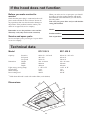
1
Gebrauchsanweisung, Libro de Instrucciones, Manuel d'utilisation
EFC 939 X
EFC 639 X
Istruzioni per l'uso,User Manual
D
E
F
I
UK
Contents
Safety instructions .............................................................................................................. 41
Description of the appliance............................................................................................... 42
Mounting of grease filters .................................................................................................................................. 42
Function ............................................................................................................................................................... 42
Exhausting version ............................................................................................................................................. 42
Recycling version ............................................................................................................................................... 42
Special accessories ............................................................................................................ 43
Active carbon filter ............................................................................................................................................. 43
Installation ............................................................................................................................ 43
Placement ............................................................................................................................................................. 43
Electrical connection .......................................................................................................................................... 43
Mounting of hood ............................................................................................................................................... 44
Exhausting version ............................................................................................................................................. 45
Recirculating version .......................................................................................................................................... 45
For both versions: ............................................................................................................................................... 45
Mounting of carbon filter (for recirculating version) ...................................................................................... 45
Using the hood .................................................................................................................... 46
Intensive speed button ........................................................................................................................................ 46
Control devices for the grease filter and carbon filter ..................................................................................... 46
Important to know .............................................................................................................................................. 46
Grease filter saturation led ................................................................................................................................. 46
Carbon filter saturation led ................................................................................................................................. 47
Correct ventilation .............................................................................................................................................. 47
Maintenance ........................................................................................................................ 47
Grease filter ......................................................................................................................................................... 47
Carbon filter ......................................................................................................................................................... 47
Cleaning ............................................................................................................................................................... 47
Changing the lighting elements ......................................................................................................................... 47
If the hood does not function ............................................................................................. 48
Service and spare parts ...................................................................................................... 48
Technical data...................................................................................................................... 48
Dimensions .......................................................................................................................................................... 48
40
Congratulations to your new Cooker Hood
Thank you for your choice of an Electrolux product. We are convinced that you will have
great use and pleasure from your new cooker hood.
Before you use the cooker hood we recommend that you read through the whole user
manual giving a direct description of the cooker hood and its functions.
To avoid the risks, that are always present when you use a product driven by electricity, it
is important that the cooker hood is installed correctly and that you read the safety instructions carefully to avoid misuse and hazard.
Save the instruction manual and keep it available at use of the cooker hood
Safety instructions
At installation and service
At use of cooker hood
l The cooker hood is made for normal households
with normal cooking. If it is used for other
purposes there is a risk of damage which is not
covered by the warranty.
l No food must be cooked flambee underneath the
hood.
l The use of an unprotected flame is dangerous
for the filters and could cause fires.
l All eventual electric installation has to be
carried out by a qualified electrician. The
installation of the hood should be made by a
person with enough knowledge. Installation
made otherwise could lead to loss of performance and even injuries and /or damage on
properties.
l Never leave the deep-frying or frying pan over a
cooker/hob. The oil contained in the pan may
spontaneously ignite through overheating.
l Observe the filter change or cleaning intervals.
Failure to observe these intervals may cause the
risk of fire through fat deposition.
l The hood cannot be connected to flues of other
appliances that run on energy sources other than
electricity.
Please, keep to the provisions of official directives regarding the question of fumes discharge.
Note! If a fire starts; Switch of the cooker hood
and the heating zone; Cover the fire , Never use
water.
l When the hood is used at the same time of other
appliances that run on energy sources other than
electricity, provision must be made for an
adequate supply of air.
At disposal
l Help to avoid damages even when the cooker
hood should be disposed. Disconnect the power
plug and cut the power cord at hood inlet. Check
with the authorities for information of how to
proceed for disposal.
l When installed, the hood must be not less than
65 cm. above electric burners or 75 cm. above
gas or mixed-fuel burners. (Fig. 3).
l The power cord should be drawn so that there is
no risk of damage. Hazard!
41
Description of the appliance
1. Control panel
2. Operating light
3. Grease filters
EFC 639
Standard accessories included:
l Screws for mounting
l Template for wall mounting
l No return valve (mounted on air outlet)
1
2
3
Mounting of grease filters
Attention! The grease filters are supplied not
mounted and packed in order to avoid damages
during transport of the hood.
l Fit the pins of the filter on the slots of the grease
filter housing, then use the handles of the filter to
lock them.
Dismount the filter the opposite way.
l Pull the handles backwards to loosen the filter
(Fig. 1).
EFC 939
1
2
3
Function
The hood may be used as follows:
- Exhausting version
- Recycling version
Fig. 1
Exhausting version
The air is vented outdoors by a 150 mm duct
which must be connected to connecting ring with
no return valve on top of the motor package.
The hood cannot be connected to
flues of other appliances that run
on energy sources other than
electricity. Please, keep to the provisions of
official directives regarding the question of
fumes discharge.
Recycling version
The air is filtered through a carbon filter and
recirculated into the room through the top sides of
the chimney (Fig. 2).
This version is used when there is no exhaust duct
for venting outdoors or when it is impossible to
install one.
Fig. 2
42
Special accessories
Active carbon filter
When the hood is used in recirculation mode an active carbon filter should be used.
Order by the retailer: PNC 942 120 182
Installation
Unpacking
Check that the cooker hood has no damages.
Transportation damages should immediately be
reported to the one responsible for the transport
Damages, faults and eventually missing details
should immediately be reported to the seller.
Take care of the packing material so that small
children cannot play with it.
Placement
The hood is to be mounted on the wall.
When installed, the hood must be not less than 65
cm. above electric burners or 75 cm. above gas or
mixed-fuel burners. (Fig. 3).
Min
65 cm
Electrical connection
Fig. 3
The hood has a power cord with moulded plug
with earth connection to be connected to a wall
outlet of 230 V.
The power outlet should be pre-mounted in such a
way that the power cord is invisible when the hood
is fully mounted.
The power cord length is 1,25 m.
As it is then hard to disconnect the
power plug for cleaning and service,
an easy accessible two pole switch
should be fitted. The switch should conform to
regulations with an opening distance between
contacts of not less than 3 mm.
43
Min
75 cm
Mounting of hood
l Fit the drilling scheme onto the wall at the right
height. (Fig. 4)
The lower edge of the scheme correspond to the
lower edge of the cooker hood.
l On the drilling scheme is printed a line corresponding to the centre of the appliance; with a
pencil draw a line up to the ceiling, this will aid
installation procedures. (Fig. 4)
l Drill as indicated on the scheme and fit
two dowels, two hooks and two screws
5x45. (Fig. 4)
Fig. 4
l Hang the hood, adjust the position using the
screws on the hooks of the hood. (Fig. 5)
l Release the grease filters. (Fig. 1)
Fig. 5
l From the inside of the hood mark on the wall
the point corresponding to the hole which will
be used to fix definitively the hood. (Fig. 6)
l Remove the hood.
l Drill two hole (Ø 8mm) and fit two dowels.
(Fig. 6)
l Hang the hood again on the hooks.
l From inside of the hood insert the definitive
fixing screws. (Fig. 6)
Fig. 6
44
l Dismount the chimney support from the chimney unscrewing the two side screws (one per
side of the chimney- conserve them). (Fig. 7)
l Dismount the deflector "b" from the chimney
support unscrewing the two screws that fix the
deflector to the chimney support (conserve the
screws). (Fig. 7)
l Fit the chimney support onto the wall close to
the ceiling.
The support has a reference mark, this must
match the line previously drawn on the wall.
(Fig. 7)
l Mark with a pencil the hole to be done and drill
the holes (Ø 8mm).
l Insert two wall dowels and fix the telescopic
chimney support with two screws 5x45. (Fig. 7)
The power plug must be disconnected
from the mains during the mounting
procedure.
Make the choice of how to use the hood:
Exhausting version
b
l Fit a Ø 150 mm exhausting pipe or flex tube on
the hood outlet on top of the motor housing and
connect it to the wall or roof outlet pipe.
a
Recirculating version
l If not already fitted, fit the connection ring (a Fig. 7) supplied (bajonett attachment - turn
clockwise and fix with a screw) on the deflector b.
l Insert the deflector in the chimney support and
fix it with two screws (Fig. 7).
l Fit a Ø 150 mm exhausting pipe on the motor
outlet connection ring sufficiently long to reach
the connection ring on the deflector.
Fig. 7
For both versions:
l Now connect the power plug to the wall outlet.
l If a no return valve is used check that it can
open correctly and is not blocked by the flex
tube
l Fix the chimney top part on its support with two
screws (Fig. 7).
l Slide the lower section of the chimney downwards and insert it on its proper housing on the
upper side of the hood (Fig. 7).
Mounting of carbon filter (for
recirculating version)
l Remove the grease filter.
l Fix the carbon filter with its two screws (Fig. 8).
l Replace the grease filter.
Fig. 8
45
Using the hood
Important to know
The hood has one variable speed motor. For the
best performance, we recommend using the low
speeds in normal conditions and the high speeds in
particular cases of strong odour and vapour concentration.
If the hood is run at the same time as a burner or
fireplace that depend on ambient air (for example
gas, Diesel, coal or wood heaters, water heaters,
etc.) be careful, because the hood, when it exhausts
the air, removes the ambient air required by the
burner or fireplace for combustion.
Not valid if the cooker hood is used in
recirculation mode.
We recommend starting up the hood a few minutes
before cooking and keeping it running until all the
odours have been eliminated.
5 MIN
0
A
B
1 2 3
F C
0
I
E F C D G
H
I
A – Motor OFF button
B – ON button and motor speed selection button 1 - 2 - 3 - 1 - 2 - . . . .
E – Speed 1 LED
F – Speed 2 LED and grease filter saturation LED (flashes)
C – Speed 3 LED and carbon filter saturation LED (flashes)
D – Intensive speed indicator LED
G – Intensive speed ON switch
H – OFF lamp button
I – ON lamp button
If the hood fails to operate correctly, briefly disconnect it from the
mains power supply for almost 5 sec. by pulling out the plug. Then
plug it in again and try once more before contacting the Technical
Assistance Service.
Intensive speed button
If the hood will be used for recirculation of air, with
carbon filter, the warning signal have to be connected
as follows: Press the buttons B and G at the same
time for about 3 seconds. The LED marked F lights
up. When the LED marked C lights up, the warning
signal is connected.
To disconnect the warning signal, press the buttons
B and G at the same time for about 3 seconds until
the LED marked C goes out.
This speed should be used when the concentration
of cooking fumes or odours is particularly strong
(for example when frying, cooking fish etc.).
The fast speed will run for about 5 minutes and
then return to the speed previously set automatically (1, 2 or 3), or switch off if no speed was
selected. To turn off the fast speed, before the end
of the 5 minutes, press button A or button B.
Grease filter saturation led
Control devices for the grease filter
and carbon filter
The LED marked F warns you when the grease
filter needs to be cleaned.
This LED flashes to warn you that the grease
filters must be cleaned.
Generally, these must be cleaned after 40 hours of
use.
Read the maintenance instructions provided for the
grease filters.
This hood has a device which warns you when to
clean the grease filter or replace the carbon filter
(in the case of the air recircultion version).
This hood is delivered without a carbon filter. For
this reason the warning signal to replace the carbon
filter is not connected.
46
Carbon filter saturation led
Correct ventilation
The LED marked C indicates carbon filter needs to
be replaced.
This must be done after approximately 160 hours of
use.
Read the instructions provided for replacing the
carbon filter.
To have the cooker hood working correctly the
windows in the kitchen should be closed. In stead
a window in an adjacent room should be open.
(Fig. 9)
To restore the LED for the filter
warnings.
After cleaning of the grease filter and exchange of
the carbon filter, press button A for about 3 seconds
until the LED F stops flashing.
Fig. 9
Maintenance
Attention
Before performing any maintenance
operation, disconnect the hood from
the electricity.
Failure to observe the rules for cleaning the appliance and changing and cleaning the filters may
cause fires. Therefore, we recommend observing
these instructions.
Grease filter
This serves to hold the grease particles in suspension.
The metal filter should be washed when the grease
filter saturation LED flashes, normally once per
month.
Wash it with warm soapy water or, if possible, in
the dishwasher (60°C).
Let dry before reinstalling.
Carbon filter
This filter dissolves cooking odours.
It should be changed when the Carbon filter
saturation LED flashes. Ask the technical assistance service or manufacturing company for a new
one.
The carbon filter must never be washed.
To remove the carbon filter, first remove the
grease metal filters and then unscrew the two
screws that holds the grease filter and pull the
filter down (Fig. 8).
Fig. 10
Changing the lighting elements
l With the help of a screwdriver remove the screw
that secures the lamp cover (Fig. 10).
l Remove the lamp cover.
l Replace the damaged part with one of equal
rating.
l Mount the lamp cover and secure it with the
screw.
Cleaning
To clean the outside of the hood use a cloth moistened with denatured alcohol or neutral liquid
detergents. Never use products containing
abrasives.
47
If the hood does not function
Before you make contact to
service
When you order service or spare parts you should
be ready to give the product number and model
denomination. This information you will find on
the rating label.
Take away the grease filter and you will find the
rating label behind.
Check that the power plug is connected to the wall
power outlet and that no fuse is blown. Do not do
any operations that can cause hazard or damage to
the product. If the problem remains contact your
dealer or an approved service company
Model:
Remember to save the purchase recite and the
Warranty card (only used in some countries)
Product number:
Service and spare parts
Date of purchase:
Service and spare parts you will get via your dealer
or service company.
Technical data
Model
EFC 939 X
EFC 639 X
Capacity
609 m3/h x) 225 m3/h
483 m3/h
246 m3/h
590 - 910 mm
898 mm
490 mm
1 x PL 11 W
2 pcs
230 V
200 W
609 m3/h x) 225 m3/h
483 m3/h
246 m3/h
590 - 910 mm
598 mm
490 mm
1 x PL 11 W
1 pc
230 V
200 W
Intensive
full speed
low speed
Dimension
Height
Width
Depth
Light (energy saving lamp)
Grease filter
Mains Voltage
Power rating total
x)
Valid when the hood is used with carbon filter (recirculation)
Dimensions
6
29
590 - 910
3
0
0
49
0
898
48
598
LI1O3A Ed. 12/00