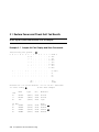
1
DEC 7000 AXP System
VAX 7000
Removable Media
Installation Guide
Order Number EK–TFRRD–IN.001
This manual is intended for Digital customer service engineers and selfmaintenance customers installing removable media in DEC 7000/10000 or
VAX 7000/10000 systems.
digital equipment corporation
maynard, massachusetts
First Printing, January 1993
The information in this document is subject to change without notice and should
not be construed as a commitment by Digital Equipment Corporation.
Digital Equipment Corporation assumes no responsibility for any errors that may
appear in this document.
The software, if any, described in this document is furnished under a license and
may be used or copied only in accordance with the terms of such license. No responsibility is assumed for the use or reliability of software or equipment that is
not supplied by Digital Equipment Corporation or its affiliated companies.
Copyright © 1993 by Digital Equipment Corporation.
All Rights Reserved.
Printed in U.S.A.
The following are trademarks of Digital Equipment Corporation:
Alpha AXP
AXP
DEC
DECchip
DEC LANcontroller
DECnet
DECUS
DWMVA
OpenVMS
ULTRIX
UNIBUS
VAX
VAXBI
VAXELN
VMScluster
XMI
The AXP logo
OSF/1 is a registered trademark of the Open Software Foundation, Inc.
FCC NOTICE: The equipment described in this manual generates, uses, and may
emit radio frequency energy. The equipment has been type tested and found to
comply with the limits for a Class A computing device pursuant to Subpart J of
Part 15 of FCC Rules, which are designed to provide reasonable protection against
such radio frequency interference when operated in a commercial environment.
Operation of this equipment in a residential area may cause interference, in which
case the user at his own expense may be required to take measures to correct the
interference.
Contents
Preface ....................................................................................................... v
Chapter 1 Preparation
1.1
1.2
Overview ................................................................................. 1-2
Kit Contents ........................................................................... 1-4
Chapter 2 Installation
2.1
2.2
Installation ............................................................................. 2-2
Removal and Replacement .................................................... 2-6
Chapter 3 Acceptance and Troubleshooting
3.1
3.2
3.3
Restore Power and Check Self-Test Results ......................... 3-2
Troubleshooting a TF85 Tape Drive ..................................... 3-4
Troubleshooting an RRD42 Compact Disk Drive ................. 3-6
Examples
3-1
Sample Self-Test Display and Show Commands ................. 3-2
Figures
1-1
2-1
2-2
2-3
2-4
3-1
Main Cabinet .......................................................................... 1-2
Control Panel Removal .......................................................... 2-2
Installation Preparation ........................................................ 2-4
Removable Media Cabling ..................................................... 2-4
Removable Media Device ....................................................... 2-6
TF85 Controls and Indicators ............................................... 3-4
iii
3-2
RRD42 CD Drive Control Panel ............................................ 3-6
Tables
1
2
1-1
1-2
1-3
3-1
3-2
iv
DEC 7000/VAX 7000 Documentation .................................... vii
Related Documents .................................................................. ix
TF85 Option Components ...................................................... 1-4
TF85D-AA Kit Contents........................................................ 1-4
RRD42-BA Option Components............................................ 1-5
TF85 Light Summary ............................................................ 3-5
RRD42 LED Summary .......................................................... 3-6
Preface
Intended Audience
This manual is written for Digital customer service engineers and selfmaintenance customers installing removable media in DEC 7000/10000 or
VAX 7000/10000 systems.
Document Structure
This manual uses a structured documentation design. Topics are organized into small sections for efficient on-line and printed reference. Each
topic begins with an abstract. You can quickly gain a comprehensive overview by reading only the abstracts. Next is an illustration or example,
which also provides quick reference. Last in the structure is descriptive
text.
This manual has three chapters, as follows:
•
Chapter 1, Preparation, gives an overview of the removable media
and tells you how to prepare for the installation.
•
Chapter 2, Installation, gives instructions on how to remove and replace the Tx85 tape drive and RRD42 compact disk drive.
•
Chapter 3, Acceptance and Troubleshooting, describes the acceptance procedure.
v
Conventions Used in This Document
Terminology. Unless specified otherwise, the use of "system" refers to
either a DEC AXP or VAX system. The DEC AXP systems use the Alpha
AXP architecture.
When a discussion applies to only one system, an icon is used to highlight
that system. Otherwise, the discussion applies to both systems. Thus, the
abstract for a module that applies only to DEC systems would look like
this:
This section shows a sample boot of OpenVMS Alpha AXP
DEC from the RRD42 CD drive for DEC 7000 systems. The first
7000
step is issuing the show device command to determine the
location of the RRD42.
Book titles. In text, if a book is cited without a product name, that book is
part of the hardware documentation. It is listed in Table 1 along with its
order number.
Icons. The icons shown below are used in illustrations for designating part
placement in the system described. A shaded area in the icon shows the
location of the component or part being discussed.
Front
Rear
Documentation Titles
Table 1 lists the books in the DEC 7000 and VAX 7000 documentation set.
Table 2 lists other documents that you may find useful.
vi
Table 1 DEC 7000/VAX 7000 Documentation
Title
Order Number
Installation Kit
EK–7000B–DK
Site Preparation Guide
EK–7000B–SP
Installation Guide
EK–700EB–IN
Hardware User Information Kit
EK–7001B–DK
Operations Manual
EK–7000B–OP
Basic Troubleshooting
EK–7000B–TS
Service Information Kit—VAX 7000
EK–7002A–DK
Platform Service Manual
EK–7000A–SV
System Service Manual
EK–7002B–SV
Pocket Service Guide
EK–7000A–PG
Advanced Troubleshooting
EK–7001A–TS
Service Information Kit—DEC 7000
EK–7002B–DK
Platform Service Manual
EK–7000A–SV
System Service Manual
EK–7002B–SV
Pocket Service Guide
EK–7700A–PG
Advanced Troubleshooting
EK–7701A–TS
vii
Table 1 DEC 7000/VAX 7000 Documentation (Continued)
Title
Order Number
Reference Manuals
Console Reference Manual
EK–70C0B–TM
KA7AA CPU Technical Manual
EK–KA7AA–TM
KN7AA CPU Technical Manual
EK–KN7AA–TM
MS7AA Memory Technical Manual
EK–MS7AA–TM
I/O System Technical Manual
EK–70I0A–TM
Platform Technical Manual
EK–7000A–TM
Upgrade Manuals
KA7AA CPU Installation Card
EK–KA7AA–IN
KN7AA CPU Installation Guide
EK–KN7AA–IN
MS7AA Memory Installation Card
EK–MS7AA–IN
KZMSA Adapter Installation Guide
EK–KXMSX–IN
DWLMA XMI PIU Installation Guide
EK–DWLMA–IN
DWMBB VAXBI PIU Installation Guide
EK–DWMBB–IN
H7237 Battery PIU Installation Guide
EK–H7237–IN
H7263 Power Regulator Installation Card
EK–H7263–IN
BA654 DSSI Disk PIU Installation Guide
EK–BA654–IN
BA655 SCSI Disk and Tape PIU
Installation Guide
EK–BA655–IN
Removable Media Installation Guide
EK–TFRRD–IN
viii
Table 2 Related Documents
Title
Order Number
General Site Preparation
Site Environmental Preparation Guide
EK–CSEPG–MA
System I/O Options
BA350 Modular Storage Shelf Subsystem Configuration Guide
EK–BA350–CG
BA350 Modular Storage Shelf Subsystem User’s
Guide
EK–BA350–UG
BA350-LA Modular Storage Shelf User’s Guide
EK–350LA–UG
CIXCD Interface User Guide
EK–CIXCD–UG
DEC FDDIcontroller 400 Installation/Problem
Solving
EK–DEMFA–IP
DEC LANcontroller 400 Installation Guide
EK–DEMNA–IN
DEC LANcontroller 400 Technical Manual
EK–DEMNA–TM
DSSI VAXcluster Installation and Troubleshooting
Manual
EK–410AA–MG
InfoServer 150 Installation and Owner’s Guide
EK–INFSV–OM
KDM70 Controller User Guide
EK–KDM70–UG
KFMSA Module Installation and User Manual
EK–KFMSA–IM
KFMSA Module Service Guide
EK–KFMSA–SV
RRD42 Disc Drive Owner’s Manual
EK–RRD42–OM
RF Series Integrated Storage Element User Guide
EK–RF72D–UG
Tx85 Series Cartridge Tape Subsystem Owner’s
Manual
EK–OTF85–OM
TLZ06 Cassette Tape Drive Owner’s Manual
EK–TLZ06–OM
ix
Table 2 Related Documents (Continued)
Title
Order Number
Operating System Manuals
Alpha Architecture Reference Manual
EY–L520E–DP
DEC OSF/1 Guide to System Administration
AA–PJU7A–TE
DECnet for OpenVMS Network Management Utilities
AA–PQYAA–TK
Guide to Installing DEC OSF/1
AA–PS2DA–TE
OpenVMS Alpha Version 1.0 Upgrade and
Installation Manual
AA–PQYSA–TE
VMS Upgrade and Installation Supplement:
VAX 7000–600 and VAX 10000–600 Series
AA–PRAHA–TE
VMS Network Control Program Manual
AA–LA50A–TE
VMSclusters and Networking
HSC Installation Manual
EK–HSCMN–IN
SC008 Star Coupler User’s Guide
EK–SC008–UG
VAX Volume Shadowing Manual
AA–PBTVA–TE
Peripherals
x
Installing and Using the VT420 Video Terminal
EK–VT420–UG
LA75 Companion Printer Installation and User Guide
EK–LA75X–UG
Chapter 1
Preparation
This chapter describes the removable media components and gives preparation guidelines for installing these options in an H9F00-Ax system cabinet or an H9F00-Bx expander cabinet. Chapter 2 describes the installation. Sections in this chapter include:
•
Overview
•
Kit Contents
Preparation 1-1
1.1 Overview
A removable media device is mounted next to the control panel in
the main system cabinet or in the front of the expander cabinet, at
the top.
Figure 1-1
Main Cabinet
Front
Rear
Removable
Media Device
DC Distribution Box
Circuit Breaker
Cooling System
Plug-In Units
BXB-0021M-92
1-2 Preparation
About the Removable Media Options
Section 1.2 lists the removable media kit contents.
DEC
7000
The RRD42 compact disk drive is used only in DEC 7000/10000
systems using the SCSI protocol. The RRD42 requires that the
system have a KZMSA adapter.
VAX
7000
The TF85 tape drive is used only in VAX 7000/10000 systems using the DSSI protocol. The TF85 requires that the system have a
KFMSA adapter.
For more information:
KFMSA Module Installation and User Manual
KZMSA Adapter Installation Guide
Preparation 1-3
1.2 Kit Contents
Table 1-1 lists the TF85 option components.
RRD42 option components.
Table 1-3 lists the
Table 1-1 TF85 Option Components
Part Number
Quantity
Description
TF85D-AA
1
In-cabinet tape storage device
(see Table 1-2)
KFMSA-BA
1
XMI to DSSI adapter for VAX systems
CK-KFMSA-LN
1
XMI to DSSI cable kit for VAX systems
Table 1-2 TF85D-AA Kit Contents
Part Number
Quantity
Description
TF85-BA
1
Tape drive — TK85-BX with DSSI controller
70-28589-01
1
Removable media assembly, DSSI, LDC,
cables
17-02382-02
1
BC21Q-09 9 foot external DSSI cable
90-09984-02
4
6-32 sems screw
EK-TFRRD-IN
1
Removable Media Installation Guide
1-4 Preparation
Table 1-3 RRD42-BA Option Components
Part Number
Quantity
Description
RRD42-AA
1
600MB CD-ROM — CD drive with SCSI
controller
70-30386-01
1
Removable media assembly, CD-ROM,
LDC, cables
17-03153-03
1
BC10U-09 9 foot external SCSI-2 cable
90-09984-20
4
6-32 M3 sems screws
EK-TFRRD-IN
1
Removable Media Installation Guide
Preparation 1-5
Chapter 2
Installation
This chapter describes the installation of removable media in the system
or expander cabinet. It contains the following sections:
•
Installation
•
Removal and Replacement
If you are adding removable media to a system, refer to Section 2.1. If you
are replacing a system’s removable media, refer to Section 2.2.
Installation 2-1
2.1 Installation
Working from the front of the cabinet, remove the control panel
and the filler panel. Slide in the removable media, replace the
control panel, and attach the cables.
Figure 2-1
Control Panel Removal
Disable
Secure
Enable
Left Expander
Restart
Front
Key On
Right Expander
Run
Fault
Console
4
7
BXB-0370A-92
2-2 Installation
Installation
NOTE: Use the antistatic wrist strap from the Electrical Safety Kit to
ground yourself to the cabinet before working with cabling and
modules.
1.
Turn the keyswitch to Disable. Remove the key.
2.
Open the rear door of the cabinet and shut the circuit breaker off (see
Figure 1-1) by pushing down the handle.
3.
Open the front door of the cabinet. Remove the console terminal cable,
if present.
4.
Remove the two Phillips screws on the left side of the control panel.
See 4 in Figure 2.1.
5.
Swing the panel to the right no more than two inches and remove it
from the hinges. If you are installing removable media in an expander
cabinet, go to step 7.
6.
Disconnect the cable from the circuit board and place the control panel
face down on a flat surface.
7.
Loosen the two captive Phillips screws at the lower side of the filler
panel. See 7 . Remove the filler panel.
8.
Slide the removable media box into the cabinet, moving aside any cables in the area. Tighten the two captive screws (slotted) at the lower
sides of the removable media box. If you are installing removable media in an expander cabinet, go to step 10.
9.
Reconnect the cable to the control panel circuit board.
10. Attach the panel to the hinges, swing it to the left, and install the two
Phillips screws that were removed in step 4.
For more information:
Platform Service Manual
Installation 2-3
Figure 2-2
Installation Preparation
1
Rear
Rear Plate
9
2
Bus Bar Cover
BXB-0435-93
Figure 2-3
Removable Media Cabling
7
8
6
3
Rear
5
4
Gray
Yellow
4
BXB-0436-93
2-4 Installation
Cabling
1.
At the rear of the cabinet, remove the enclosure rear plate (attached
with three Phillips screws). See 1 in Figure 2-2.
2.
Using a nutdriver, remove the two nuts holding the plastic cover on
the DC distribution box. See 2 . Remove the cover.
3.
Attach the 48VDC yellow and gray power cable (17-03508-01) to the
MAT-N-LOCK connector at the lower right of the removable media
box. See 3 in Figure 2-3.
4.
Attach the gray end to one of the gray colored terminals of the upper
bus bar and the yellow end to one of the yellow colored terminals of
the lower bus bar. See 4 .
5.
Replace the plastic cover, being careful not to loosen the connector (cable 17-03124-01) at 5 .
6.
Attach one end of the signal cable (17-03123-01) to the 20-pin connector at the upper right of the removable media box. See 6 . Expander
cabinets use the pre-installed cable 17-03442-01. Attach the other end
to connector J3 located toward the front of the CCL module.
7.
Place a DSSI (12-31281-01) or SCSI terminator (12-37618-01) on the
right DSSI connector or left SCSI connector of the removable media
box. See 7 .
8.
Attach the DSSI (BC21Q-09) or SCSI cable (BC10U-09) to the
unterminated connector of the removable media box. See 8 .
9.
Route the cable to the left of the two plastic covers on the DC distribution box (see 9 in Figure 2-2), down the left side and along the bottom
edge (using clips) of the cooling system housing (see Figure 1-1), and
attach the other end to the XMI bulkhead connector.
10. Replace the plate (removed in step 1) at the rear of the removable media box.
Installation 2-5
2.2 Removal and Replacement
The removable media device is housed in a box mounted on rails
in the cabinet. Slotted captive screws hold the box in the cabinet.
Access is from the front of the cabinet.
Figure 2-4
Removable Media Device
Front
4
BXB-0371B-92
2-6 Installation
Removal
1.
Turn the keyswitch to Disable. Remove the key.
2.
Open the rear door of the cabinet and shut the circuit breaker off (see
Figure 1-1) by pushing down the handle. Remove the rear plate (see
Section 2.1), and remove the cables from the removable media box.
3.
Remove the control panel (see Section 2.1).
4.
Loosen the two captive screws (slotted) at the lower sides of the removable media box. See 4 in Figure 2-4.
5.
Slide the removable media box out of the cabinet.
Replacement
•
Reverse the steps in the Installation procedure in Section 2.1.
For more information:
Platform Service Manual
Installation 2-7
Chapter 3
Acceptance and Troubleshooting
This chapter discusses the acceptance procedure and troubleshooting
guidelines for the removable media options. Sections include:
•
Restore Power and Check Self-Test Results
•
Troubleshooting a TF85 Tape Drive
•
Troubleshooting an RRD42 Compact Disk Drive
Acceptance and Troubleshooting 3-1
3.1 Restore Power and Check Self-Test Results
Power up the system and check the self-test display.
Example 3-1 Sample Self-Test Display and Show Commands
Initializing the system...
1
F
E
D
C
B
A
9
8
A
o
.
o
.
+
.
7
M
+
.
+
.
+
.
6
.
.
.
.
.
.
.
5
.
.
.
.
.
.
.
4
.
.
.
.
.
.
.
3
.
.
.
.
.
.
.
2
.
.
.
.
.
.
.
1
.
.
.
.
.
.
.
+
.
.
.
.
.
.
.
.
.
.
.
.
.
.
.
.
.
.
.
+
.
.
.
+
.
.
.
.
.
.
.
.
.
.
.
+
.
.
.
.
.
.
.
.
.
.
.
.
.
.
.
.
.
.
.
. A0 .
. 128 .
.
.
.
.
.
.
.
.
.
.
0
P
+
B
+
B
+
B
NODE #
TYP
ST1
BPD
ST2
BPD
ST3
BPD
C0 XMI +
C1
C2
C3
.
.
ILV
128Mb
Firmware Rev = V1.0-1625 SROM Rev = V1.0-0 SYS SN = GAO1234567
# DEC 7000 example
>>> show config 2
Name
Type
Rev
Mnemonic
KN7AA
MS7AA
IOP
(8001)
(4000)
(2000)
0000
0000
0002
kn7aa0
ms7aa0
iop0
C0 XMI
5+
KZMSA
8+
DWLMA
9+
KZMSA
E+
DEMNA
(0C36)
(102A)
(0C36)
(0C03)
003E
0104
003E
060B
xmi0
kzmsa0
dwlma0
kzmsa1
demna0
LSB
0+
7+
8+
3-2 Acceptance and Troubleshooting
3
4
Example 3-1 Sample Self-Test Display and Show Commands
(Continued)
>>> show device kzmsa0 5
# DEC AXP example
polling for units on kzmsa0, slot 13, xmi0...
dka0.0.0.13.0
DKA0
RRD42
>>> show device kfmsa0 5
# VAX example
polling for units on kfmsa0, slot 3, xmi0...
dub120.5.0.3.0
$1$DIA120 (SFL2LR)
RF72
dub122.6.0.3.0
$1$DIA122 (SFL2LF)
RF72
muc9.0.1.3.0
$1$MIA9
(V9TF85)
TF85
>>>
1.
Pull up the handle on the AC power circuit breaker.
2.
Close the cabinet doors.
3.
Turn the control panel keyswitch to the Enable position; the system
will power up and run self-test.
In Example 3-1:
1
Self-test runs at power-up.
2
The user enters a show config command.
3
The first KZMSA adapter, kzmsa0, passes self-test. Kzmsa0 supports
the in-cabinet RRD42 CD drive.
4
The second KZMSA adapter, kzmsa1, also passes self-test. This
adapter supports the devices in the SCSI PIU.
5
The user enters a show device kzmsa0 (DEC AXP) or kfmsa0
(VAX) command. You can check to see if all the devices associated
with the KZMSA or KFMSA adapter are reported by issuing this
command.
For more information:
Basic Troubleshooting
Advanced Troubleshooting
Acceptance and Troubleshooting 3-3
3.2 Troubleshooting a TF85 Tape Drive
Check the controls and indicators on the TF85 tape drive.
VAX Table 3-1 lists the functions of the controls and indicators
7000
shown in Figure 3-1.
Figure 3-1
se
d
U
g
te
n
te le
in
i
e ec
ra nd
an e
rit ot ape
pe a
se le p
W Pr
T
U C Ta O H
ad ht
Lo
g
Li
To
t
ai s
W thi
n
pe e
O n dl e
p
a
H Ta
rt
se
In this
se
lo e
C n dl
a
H
d
oa
nl
U tton
To Bu ht
s
g
Li
es
Pr
t
ai s
W thi
n
pe e
O ndl ape
T
a
H ve
o
em
R
Front
TF85 Controls and Indicators
85 nload
TF U
BXB0017-92
3-4 Acceptance and Troubleshooting
Table 3-1 TF85 Light Summary
Light
State
Condition
Write Protected
(Orange)
On
Off
Tape write protected.
Tape write enabled.
Tape in Use
(Yellow)
Steady
Blinking
Drive ready.
Drive in use.
Use Cleaning Tape
(Orange)
On
Off
Drive needs cleaning.
No cleaning needed.
Operate Handle
(Green)
On
Off
Blinking
OK to operate handle.
Do not operate handle.
Defective cartridge. Pull the
handle to the open position
and remove cartridge. Try
another cartridge.
All four lights
Blinking
Drive fault. Reset by pressing the unload button.
For more information:
Tx85 Cartridge Tape Subsystem Owner’s Manual
Acceptance and Troubleshooting 3-5
3.3 Troubleshooting an RRD42 Compact Disk Drive
Table 3-2 lists the functions of the green LED on the RRD42
DEC compact disk (CD) drive.
7000
Figure 3-2
RRD42 CD Drive Control Panel
Front
Green LED
BXB-0380-92
Table 3-2 RRD42 LED Summary
LED
State
Condition
Green
(Activity)
Off
On
No activity
Data is being transferred
For more information:
RRD42 Disc Drive Owner’s Manual
3-6 Acceptance and Troubleshooting
Index
C
T
Cabling, 2-4
Control panel, 1-2, 2-3
TF85
lights, 3-5
troubleshooting, 3-4
TF85D-AA kit contents, 1-4
TF85 option components, 1-4
D
DC distribution box, 2-5
E
Expander cabinet, 1-2
F
Filler panel, 2-2
K
KFMSA adapter, 1-3
KZMSA adapter, 1-3
R
Rear plate, 2-5
Removable media installation, 2-6
Replacement
removable media, 2-7
RRD42
LEDs, 3-6
troubleshooting, 3-6
RRD42-BA option components, 1-5
S
Self-test results, 3-2
Signal cable, 2-5
System cabinet, 1-2
Index-1