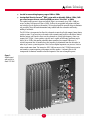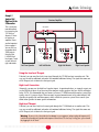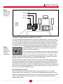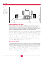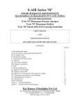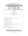
1
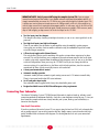
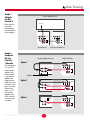
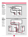
Atlantic Technology
®
I
N N O V A T I V E
H
O M E
T
H E A T E R
343 Vanderbilt Avenue Norwood, MA 02062 (781) 762-6300 www.atlantictechnology.com
Instruction Manual
Model 172 PBM
High Performance Powered Subwoofer
Model 172 PBM
MODEL 172 PBM
High Performance Powered Subwoofer
Congratulations on your purchase of an Atlantic Technology 172 PBM
powered subwoofer. With proper care, your new subwoofer will
provide many years of trouble-free performance.
The 172 PBM is capable of delivering very high output levels and wide
dynamic range. When properly placed it will provide smooth in-room
bass response down to approximately 20 Hz, with a peak SPL of 108dB
(1800 cubic foot space).
The built-in proprietary high-current Class G amplifier is conservatively rated at 150 watts RMS. This amplifier, coupled with a massive
12" long-throw woofer in a sealed enclosure, generates musically
accurate deep bass with a minimum of distortion.
Your Atlantic Technology powered subwoofer will smoothly integrate
with virtually all other brands of loudspeakers on the market as all its
internal electronics have been designed to maintain optimum signal integrity. From the premium
quality gold plated connectors to the clearly marked controls, this is one of the most versatile high
performance subwoofers you can buy. An added benefit is its relatively compact size and straight
forward design.
Features
Your Atlantic Technology powered subwoofer has been engineered using the latest technology and
finest components available. It features:
●
A long-throw 12" driver with vented motor structure and 2", high-temperature, 4-layer voice coil
This powerful driver has a very stiff cone that acts as an almost perfect piston throughout its
operating range. Its massive magnetic motor assembly and high temperature component parts
deliver high performance and exceptional reliability. In fact, the 9.5 pound motor assembly is
identical to the one in our top of the line 15 inch subwoofers!
●
A sealed enclosure for low distortion and deep bass output
Sealed enclosure designs are inherently low in distortion and naturally deliver deep, smooth bass
response with a gradual and predictable roll-off below resonance. As with all Atlantic Technology
subwoofers, we have paid inordinate attention to giving you accurate musical bass reproduction
along with terrific special effects.
●
A linear power high current Class G amplifier conservatively rated at 150 watts RMS
Atlantic Technology’s advanced Class G amplifiers utilize dual low voltage/high voltage power
supplies for exceptional power delivery from a compact and efficient package. One power supply
operates during all “normal” demand periods. But, when a high demand peak signal appears at
the subwoofer input, the second, high voltage supply switches in to dramatically boost the amplifier’s low distortion output capability. The amplifier delivers very high power levels yet consumes
less steady-state power and produces much less heat than standard comparable amplifier designs.
The 172 PBM’s custom designed amplifier has been precision matched and equalized to its 12”
driver. It exerts accurate and powerful control over the driver for the best performance possible.
○ ○ ○ ○ ○ ○ ○ ○ ○ ○ ○ ○ ○ ○ ○ ○ ○ ○ ○ ○ ○ ○ ○ ○ ○ ○
2
○ ○ ○ ○ ○ ○ ○ ○ ○ ○ ○ ○ ○ ○ ○ ○ ○ ○ ○ ○ ○ ○ ○ ○ ○ ○
Atlantic Technology
®
●
A useful in room working frequency range of 20Hz to 150Hz
●
A unique Dual Diversity CrossoverTM (DDC) system with an adjustable (50Hz to 150Hz) 12dB
per octave low-pass crossover, and a fixed 24dB per octave “voice filter” at 180Hz.
This sophisticated crossover’s upper end roll-off slope is an extremely steep 12dB + 24dB per
octave, totaling 36dB per octave above 180Hz. It allows for exceptional integration with most
any brand or type of speaker on the market. We have developed this unusual design to eliminate
any possibility of out-of-band information being audible from the subwoofer and thereby
making it localizable.
The DDC filter is incorporated to allow this subwoofer to match well with compact home theater
speaker systems. If you are using a subwoofer with extremely small satellites which have limited
mid-bass output you’ll need to cross over the subwoofer at a fairly high frequency. Since very
compact Left / Right / Center speakers typically aren’t capable of delivering significant output
below 100 to 125Hz, their mating subwoofer must reproduce these sounds. However, it’s
critically important that all sounds above this frequency be eliminated from the subwoofer, in
order to get correct system integration. This is because higher frequencies are your ears’ clues to
where sound comes from. The innovative DDC 36dB crossover in the 172 PBM ensures precise
and seamless system integration with compact satellite speakers. A subsonic filter is also
incorporated to eliminate inaudible ultra-low frequencies that can rob amplifier power.
Figure 1:
Amplifier panel
and controls for
Model 172 PBM
○ ○ ○ ○ ○ ○ ○ ○ ○ ○ ○ ○ ○ ○ ○ ○ ○ ○ ○ ○ ○ ○ ○ ○ ○ ○
3
○ ○ ○ ○ ○ ○ ○ ○ ○ ○ ○ ○ ○ ○ ○ ○ ○ ○ ○ ○ ○ ○ ○ ○ ○ ○
Model 172 PBM
IMPORTANT NOTE - Only if you are NOT using the complete System 170: If you are using a
surround receiver/processor that includes its own filtered subwoofer output and ultra-compact satellites, we
strongly recommend that you connect the 172 PBM to your system using the high level (speaker) inputs. This
is because most receiver/processor internal crossovers are 12dB per octave, which isn’t steep enough for use
with the higher crossover levels required for ultra-compact satellites. In such a case, only use the low level RCA
inputs when the processor outputs unfiltered signals. Should your processor include a 120Hz crossover, and a
slope of 18dB or higher, you may connect it to the low level inputs on the 172 PBM.
●
Two line inputs, two line thruputs
The thruputs allow daisy chaining of multiple subwoofers, or can act as a return path back to the
processor.
●
Two high level inputs, two high level thruputs
These let you connect the subwoofer to your amplifier using the amplifier’s speaker outputs.
Once again, you can daisy chain to another subwoofer using the unmodified signal that comes
out of the thruput connectors.
●
A Phase Invert toggle switch (Normal/Invert)
This switch allows precise acoustic matching with speaker systems whose output may be phase
reversed. This switch also allows you to compensate for unusual room acoustics that occur when
a woofer is physically separated from the midrange/high frequency units. Be sure to try the Phase
switch in both positions when you set up the 172 PBM. Even if you just change the built-in
crossover settings it’s a good idea to try the Phase switch in both positions, since the crossover
control and the Phase switch acoustically interact with each other.
●
A front panel mounted level control
●
Automatic standby operation
Automatic standby features automatic signal sensing turn on and a 7-10 minute turn-off delay.
There’s a front panel multi-color LED status indicator.
●
An AC cord power input socket
Your subwoofer comes supplied with a heavy-duty detachable power cord.
●
Designed and built to meet all UL/CSA and European safety requirements
Connecting Your Subwoofer
The Atlantic Technology System 172 PBM Powered Subwoofer is simple to hook up, offering several
connection methods for maximum flexibility. Study the system diagrams starting on page 5. Once you
have found the example which most closely matches your system, hook up your subwoofer(s) as
shown in that diagram.
Low-Level Connection
If you have purchased the entire System 170, we suggest using the low-level (RCA jack) subwoofer line
out or preamp output if your receiver/processor has one. Simply connect your subwoofer with high
quality shielded cables as shown in the diagrams. Use the diagram that best suits your connection
requirements.
○ ○ ○ ○ ○ ○ ○ ○ ○ ○ ○ ○ ○ ○ ○ ○ ○ ○ ○ ○ ○ ○ ○ ○ ○ ○
4
○ ○ ○ ○ ○ ○ ○ ○ ○ ○ ○ ○ ○ ○ ○ ○ ○ ○ ○ ○ ○ ○ ○ ○ ○ ○
Atlantic Technology
®
Example 1:
Subwoofer
Line Out/
Low Level In
Receiver/Amplifier/Processor
Before using this
connection
method, please
see the Important
Note on page 4.
Sub Woofer Out
LOW
LEVEL
THRU
LOW
LEVEL
THRU
IN
L/
MONO
L/
MONO
IN
IN
R
R
HIGH
LEVEL
HIGH
LEVEL
Single Sub Woofer
Example 2:
Preamp Line
Out/Low
Level In for
1 Subwoofer
This arrangement
is for owners of
stereo receivers/
amplifiers with
Preamp outputs.
If your receiver/
amplifier uses
jumper links between the Pre-out
and Main In, then
you must remove
them and use
option 1 or 2. If
your receiver/
amplifier uses a
switch instead of
connectors, then
use option 3.
IN
Optional Second Sub Woofer
Receiver/Amplifier/Processor
Single Sub Woofer
Option 1
L
LOW
LEVEL
R
THRU
Pre Out
IN
L/
MONO
IN
Main In
R
HIGH
LEVEL
Y-adapters
Option 2
L
LOW
LEVEL
R
THRU
IN
Pre Out
L/
MONO
IN
Main In
R
HIGH
LEVEL
Option 3
Pre Amp
L
R
LOW
LEVEL
Internal
External
THRU
Pre Out
IN
L/
MONO
IN
Main In
R
HIGH
LEVEL
○ ○ ○ ○ ○ ○ ○ ○ ○ ○ ○ ○ ○ ○ ○ ○ ○ ○ ○ ○ ○ ○ ○ ○ ○ ○
5
○ ○ ○ ○ ○ ○ ○ ○ ○ ○ ○ ○ ○ ○ ○ ○ ○ ○ ○ ○ ○ ○ ○ ○ ○ ○
Model 172 PBM
Example 3:
Preamp Line
Out/Low Level
In for
2 Subwoofers
Receiver/Amplifier/Processor
Y-adapters
L
R
Pre Out
Note that the
L/MONO input is
used on both subwoofers. Instead
of Y-adapters, you
may also use the
THRU outputs to
connect back to
the Main Inputs as
shown in Option
2 of Example 2.
Main In
LOW
LEVEL
THRU
LOW
LEVEL
THRU
IN
L/
MONO
IN
L/
MONO
IN
IN
R
R
HIGH
LEVEL
HIGH
LEVEL
Left Sub Woofer
Example 4:
Speaker Out/
High Level In for
1 Subwoofer
Right Sub Woofer
Receiver/Amplifier
Main Speakers
This is the
recommended
method for
connecting the
172 PBM to a
discrete 5.1
channel. Please
the Important
Note on page 4.
Left
Right
LOW
LEVEL
THRU
IN
L/
MONO
IN
R
HIGH
LEVEL
L
THRU
R
Sub Woofer
Left Front Speaker
○ ○ ○ ○ ○ ○ ○ ○ ○ ○ ○ ○ ○ ○ ○ ○ ○ ○ ○ ○ ○ ○ ○ ○ ○ ○
6
Right Front Speaker
○ ○ ○ ○ ○ ○ ○ ○ ○ ○ ○ ○ ○ ○ ○ ○ ○ ○ ○ ○ ○ ○ ○ ○ ○ ○
Atlantic Technology
®
Example 5:
Speaker Out/
High Level In for
2 Subwoofers
Receiver/Amplifier
This is the recommended method
for connecting the
172 PBM to a
discrete 5.1 channel receiver or
amplifier. Please
see the Important
Note on page 4.
You can also use
the speaker level
THRU outputs.
Note that the
L/MONO High
Level input is used
on both left and
right subwoofers.
Main Speakers
Left
Right
LOW
LEVEL
THRU
IN
LOW
LEVEL
THRU
L/
MONO
L/
MONO
IN
R
IN
R
HIGH
LEVEL
Left Front Speaker
IN
Left Sub Woofer
HIGH
LEVEL
Right Sub Woofer
Right Front Speaker
Using the Low-level Thruput
If desired, you can run a line level stereo signal through the 172 PBM and out to another unit. This
way you can add an additional subwoofer with minimal additional wiring. The signal that comes out
of the Thruput jacks is identical to the input signal.
High-Level Connection
Alternately, you may use the high-level (speaker) inputs. As mentioned above, we strongly suggest you
use the High-level inputs if you are using ultra-compact satellite speakers that have little or no output
below 125 Hz. We recommend that you connect your new 172 PBM Powered Subwoofer(s) using high
quality wire of 16 gauge or larger. There are many respected manufacturers in the audio industry that
specialize in speaker wire and interconnect cables suitable for your new system. Please consult your
audio/video specialist for more specific information.
High-level Thruput
If desired, you can run a high level stereo signal through the 172 PBM and out to another unit. This
way you can add an additional subwoofer with minimal additional wiring. The signal that comes out
of the Thruput jacks is identical to the input signal.
Warning: To prevent risk of electrical shock or damage to your equipment, always unplug all component AC
cords before proceeding with speaker and component connections! The last step in wiring your system should
be plugging in the AC cords!
○ ○ ○ ○ ○ ○ ○ ○ ○ ○ ○ ○ ○ ○ ○ ○ ○ ○ ○ ○ ○ ○ ○ ○ ○ ○
7
○ ○ ○ ○ ○ ○ ○ ○ ○ ○ ○ ○ ○ ○ ○ ○ ○ ○ ○ ○ ○ ○ ○ ○ ○ ○
Model 172 PBM
Note: Due to the very close placement of the High-level connectors, the most practical connectors to use are
“double banana plugs” (North America only) available from most electronic supply stores.
You can connect to the High-level inputs by using a variety of connectors, or by removing 1/2" of
insulation from each wire end, twisting the strands of wire together, placing the wire through one of
the post holes and screwing down the nut tightly. We recommend that you check your local electrical
codes to make sure you are not using an improper connector.
Figure 2:
Gold plated
5-way binding
posts. Accepts
up to 10 gauge
bare wire
It is important to observe polarity while making speaker connections:
red (+) terminals on the amplifier to red (+) on the speaker, black (-) on
the amplifier to black (-) on the speaker. Look carefully at the wires you
are using and note that one of the wires in each pair will be marked by
either the conductor color, printing on the wire jacket, a ridge on one
side of the wire jacket, or a thread intertwined with the wire strands. By
convention, the marked wire is connected to the red (+) terminal.
Power Connection
Connect the power cord to an AC outlet only after making all other connections to the subwoofer.
This will avoid any chance of accidentally activating the subwoofer while wiring. Atlantic Technology
does not recommend plugging the subwoofer into the switched outlet of an amplifier, preamplifier,
or receiver. The power demands of the subwoofer amplifier may exceed the power rating of the
switched outlet and may damage the equipment.
The 172 PBM is totally automatic in its operation. The automatic on/off circuitry will only activate the
subwoofer in the presence of an audio signal from your audio/video system. After 7-10 minutes with
no signal detected from the rest of the system, the amplifier will shut itself off and go into standby
mode. When an audio signal is present, the power LED located under the front grille will glow green.
Power consumption in the standby mode is negligible. Standby operation can be completely bypassed
by plugging the 172 PBM into a heavy-duty switched power outlet strip if you desire. In this mode, the
subwoofer will be powered when the power switch is turned on and it will still operate in automatic
standby/on mode when the power strip is active.
Placement and Operation
Generally speaking, the best location for your new Subwoofer will be in the front of the room, in or
close to a corner (Figure 3). Every room has its own unique sound characteristics, and flexibility in the
exact placement of the subwoofer is always desirable. The closer the subwoofer is placed to a wall and
especially a corner, the more and deeper the bass response you will hear. However, in some rooms,
corner placement can produce too much bass or a “one note” boomy effect. Under such circumstances
the subwoofer may work better away from the corner. You should experiment to find the best position
in your room.
Helpful Hint: A particularly useful experiment is to place the subwoofer right at the prime listening position
(move that couch or chair out of the way and put the sub in its place). Then play something with lots of good
bass (preferably music), and walk around the room, listening to the subwoofer’s response. When you locate an
area that has ample amounts of well defined bass you have found a good potential place to locate the sub.
○ ○ ○ ○ ○ ○ ○ ○ ○ ○ ○ ○ ○ ○ ○ ○ ○ ○ ○ ○ ○ ○ ○ ○ ○ ○
8
○ ○ ○ ○ ○ ○ ○ ○ ○ ○ ○ ○ ○ ○ ○ ○ ○ ○ ○ ○ ○ ○ ○ ○ ○ ○
Atlantic Technology
®
Figure 3:
Typical arrangement for a single
subwoofer in a
home theater.
Start here
Less Bass
More Bass
Subwoofer Tuning Using the Variable Level Control
Figure 4:
Front Panel
Variable Level
Control located
behind the
removable grille.
Start your listening with the subwoofer Lo-pass control set at approximately 1/3 of its range (which
corresponds to 90Hz), the phase switch set to normal, and the front panel variable level control (Figure
5) set to the bottom of its range (fully counterclockwise facing the front of the woofer). Play some
music that you know has good bass content, and turn the level control up until you just start to hear
the subwoofer working. Now, from your normal listening position, determine whether the subwoofer
is playing loudly enough and filling in the bass frequencies of the music
evenly. If adjustment is necessary, start by changing the setting of the front
panel level control to compensate.
If the bass seems too heavy, move the subwoofer away from the wall/corner. If
the bass seems too thin, move the subwoofer closer to the wall/corner. Small
differences in positioning can make big differences in bass response. When
you find a position that seems to work well, try switching the phase switch between its two settings,
listening particularly to the transition from the subwoofer to the satellites.
Sometimes people prefer more bass impact for movies than sounds natural when reproducing music.
You may wish to determine both a video level and an audio level if you find yourself falling into this
camp. Remember however, the most common error people make when setting up their system is to
play the subwoofer too loudly. Of course, the Bass Police will not arrest you for this act. But should you
desire the most accurate overall reproduction, a well balanced sound from bass to highest treble is the
best way to get it. Have fun. Experiment. Enjoy.
Dual Subwoofer Placement
When two subwoofers are used you may wish to place them asymmetrically; that is, in slightly
different positions in the room (Figure 5). This will reduce common mode room resonances that are
common to symmetrically positioned subwoofers. You can also try placing the subwoofers in the same
corner, if you wish, Experiments have shown this to be a viable means of producing smooth bass
response in many rooms.
○ ○ ○ ○ ○ ○ ○ ○ ○ ○ ○ ○ ○ ○ ○ ○ ○ ○ ○ ○ ○ ○ ○ ○ ○ ○
9
○ ○ ○ ○ ○ ○ ○ ○ ○ ○ ○ ○ ○ ○ ○ ○ ○ ○ ○ ○ ○ ○ ○ ○ ○ ○
Model 172 PBM
Figure 5:
Assymmetrical
arrangement for
2 subwoofers in
a home theater,
for example, one
closer to a corner
than the other.
Using the Subwoofer Lo-Pass Control
When used with the complete System 170, the 172 PBM Lo-pass control should be set at 1/3 of its
range to begin with. The goal is to optimize the performance of the system by ensuring that the subwoofer and satellites produce a cohesive and well integrated sound “picture.” The low frequency
response of the System 170 satellites has been optimized to work with approximately a 90Hz crossover
point. This provides maximum performance and smooth integration with the subwoofer.
Higher crossover frequencies pass more bass but can sound boomy and may be more easily localized to
the subwoofer. Higher crossover frequencies may be suitable, however, when using very small satellites
that have no real low frequency performance. Settings lower than 90Hz should be employed if you are
using larger speakers that have extended bass response. This way, the subwoofer will only reproduce
the very lowest bass frequencies that are in the range where the large main speakers begin to roll off.
It’s generally undesirable to have the main speakers and the subwoofer overlap too much. Larger
speakers means a lower Lo-pass crossover frequency, smaller speakers means a higher Lo-pass crossover
frequency. Consult the manufacturer’s specified low frequency response for your main speakers to
determine the appropriate Lo-pass setting on your subwoofer. In the end, however, a little time spent
experimenting will generally result in dramatically better bass response.
The Phase Invert Control
A subwoofer operating out of phase with the rest of the system won’t provide optimum low frequency
performance. Also, the correct subwoofer phase can enhance room acoustics. Since there is so much
variation in the industry regarding phase, and no standards have been established, a switch that will
reverse the phase of the subwoofer is provided on the amplifier panel. Listen to a monaural musical
source with strong bass content. (For example, you can use the mono switch on an FM tuner or
preamp, or use a Y-connector on the outputs of one of your source components to get a mono signal.)
Experiment with the position of the phase switch to get the most extended bass. It should be obvious
which is the correct setting. In particular, there will be a smother more integrated transition between
the satellites and the subwoofer when they are properly phased.
○ ○ ○ ○ ○ ○ ○ ○ ○ ○ ○ ○ ○ ○ ○ ○ ○ ○ ○ ○ ○ ○ ○ ○ ○ ○
10
○ ○ ○ ○ ○ ○ ○ ○ ○ ○ ○ ○ ○ ○ ○ ○ ○ ○ ○ ○ ○ ○ ○ ○ ○ ○
Model 172 PBM
Model 172 PBM Specifications
Type/Features
Powered Subwoofer with Sealed Acoustic-Suspension Enclosure
Variable 50-150 Hz, 12 dB/Octave low pass output
Fixed 24 dB/Octave 180 Hz Low-Pass Filter
Dual Diversity Crossover System (DDC)™
Driver
(1) 12" long-throw woofer, 2”, 4 layer vented aluminum voice coil, vented
motor system
Amplifier Power
150 Watts RMS all discrete linear Class G power amplifier with dual
power supplies
Amplifier Distortion <0.025%
Frequency Response 20-180 Hz ±3dB
Peak output (SPL)
108dB
Dimensions
13.8in x 19.7in x 13.8in; 350mm x 500mm x 350mm
Weight
42.75lbs.; 19.4kg.
Specifications are those in effect at the time of printing. Atlantic Technology reserves the right to change specifications or designs at any time without notice. Dolby Digital, AC-3,
Dolby Stereo and Dolby Pro Logic are trademarks of Dolby Laboratories Licensing Corporation. DTS is a registered trademark of DTS Technology.
For Future Reference
Record your speaker serial number and date of purchase here:
Model Number
Serial Number
Date of Purchase
The serial number is found on the back of the speaker near the connecting terminals.
CAUTION: To reduce the risk of electric shock, do not remove
the cover (or back). No user serviceable parts inside. Refer to
qualified personnel.
WARNING: To reduce the risk of fire or electric shock, do not
expose this appliance to rain or moisture.
The lightning flash with arrowhead, within an
equilateral triangle, is intended to alert the user
to the presence of uninsulated “dangerous
voltage” within the product’s enclosure that
may be of sufficient magnitude to constitute a
risk of electrical shock to persons.
The exclamation point within an equilateral
triangle is intended to alert the user to the
presence of important operating maintenance
(servicing) instructions in the literature
accompanying the appliance.
○ ○ ○○ ○○ ○○ ○○ ○○ ○○ ○○○○○ ○○ ○○ ○○ ○○ ○○ ○○ ○○ ○○ ○○ ○○ ○○ ○○ ○○ ○○ ○○ ○○ ○○ ○○
○○ ○○ ○○ ○○ ○○ ○○ ○○ ○○ ○○ ○○ ○○ ○○ ○○ ○○ ○○ ○○ ○○ ○○ ○○ ○○ ○○ ○○ ○○ ○○ ○○ ○○ ○ 12
010-1172