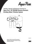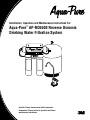
1
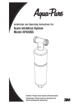
Installation, Operation and Maintenance Instructions For:
Aqua-Pure® AP-RO5500 Reverse Osmosis
Drinking Water Filtration System
Installer: Please leave manual with homeowner.
Homeowner: Please retain for operation and future
maintenance instructions.
SAFETY INFORMATION
Read, understand, and follow all safety information contained in these instructions prior to installation and use of the AP-RO5500 Reverse Osmosis (RO) Drinking Water Filtration System.
Retain these instructions for future reference.
Intended use:
The Aqua-Pure® AP-RO5500 Reverse Osmosis Drinking Water Filtration System is intended for use in filtering
drinking water in residential locations and has not been evaluated for other uses. The system is typically installed
beneath or near a kitchen sink, and it is recommended that the installation be performed by a qualified installation
specialist or a licensed plumber.
EXPLANATION OF SIGNAL WORD CONSEQUENCES
WARNING
Indicates a potentially hazardous situation, which, if not avoided, could result in
death or serious injury and/or property damage.
CAUTION
Indicates a potentially hazardous situation which, if not avoided, may result in
minor or moderate injury and/or property damage.
CAUTION
Indicates a potentially hazardous situation, which, if not avoided, may result in
property damage.
WARNING
To reduce the risk associated with choking:
• Do not allow children under 3 years of age to have access to small parts during the installation of this product.
To reduce the risk associated with ingestion of contaminants:
• Do not use with water that is microbiologically unsafe or of unknown quality without adequate disinfection before or after the system. Systems certified for cyst reduction may be used on disinfected water that may contain
filterable cysts. EPA Establishment Number 070595-CT-001
To reduce the risk associated with a hazardous voltage due to an installer drilling through existing
electric wiring or water pipes in the area of installation:
• Do not install near electric wiring or piping which may be in the path of a drilling tool when selecting the
position to mount the filter bracket.
To reduce the risk associated with the ingestion of contaminants:
• An approved air gap must exist between the RO system reject drain line and the drain opening to comply
with state and local plumbing codes.
To reduce the risk of physical injury:
•All hydro-pneumatic pressurized tanks must have an appropriate pressure relief valve installed.
To reduce the risk associated with irritation from Sodium Metabisulfite during installation:
• Sodium Metabisulfite (CAS 007681-57-4) is used in a 1% preservative solution within the reverse osmosis
membrane.
• Do not put this system into service before the RO tank is flushed as specified in the installation instructions.
Wear eye and face protection during installation.
• To request an MSDS relating to this product call 203-238-8965 or visit the web at http://solutions.3m.com/wps/
portal/3M/en_us/msds (click MSDS search). For emergencies, call 800-364-3577 or 651-737-6501
(24 hours).
2
WARNING
To reduce the risk associated with ingestion of water contaminated with sanitizer:
• After installation, sanitizer MUST be flushed from the system before first use as directed within the
installation instructions.
To reduce the risk of eye injury while drilling counter-tops for faucet installation:
•Safety glasses MUST be worn during sink hole drilling operations.
CAUTION
To reduce the risk associated with property damage due to water leakage:
• Read and follow all Instructions before installation and use of this system.
• Installation and Use MUST comply with all state and local plumbing codes.
• Protect from freezing. Drain filter when temperatures drop below 40°F (4.4°C).
• Do not install systems in areas where ambient temperatures may go above 110° F (43.3°C).
• Do not install if water pressure exceeds 125 psi (862 kPa). If your water pressure exceeds 80 psi, you
must install a pressure limiting valve. Contact a plumbing professional if you are uncertain how to check
your water pressure.
• Do not install where water hammer conditions may occur. If water hammer conditions exist you must install a
water hammer arrester. Contact a plumbing professional if you are uncertain how to check for this condition.
• Where a backflow prevention device is installed on a water system, a device for controlling pressure due to
thermal expansion must be installed.
• Do not install on hot water supply lines. The maximum operating water temperature of this system is 100°F
(37.8°C).
• Do not use a torch or other high temperature sources near filter or plastic fittings.
• Do not install in direct sunlight or outdoors.
• Do not install near water pipes which will be in path of a drilling tool when selecting the position to mount
the bracket.
• Ensure that the location and fasteners will support the weight of the system when installed and full of water.
• Mount filter in such a position as to prevent it from being struck by other items used in the area of installation
(waste baskets, etc).
• On plastic fittings, never use pipe sealant or pipe dope. Use PTFE thread tape only, pipe dope properties may
deteriorate plastic.
• Take care when using pliers or pipe wrenches to tighten plastic fittings, as damage may occur if over
-tightening occurs.
• Ensure all tubing and fittings are secure and free of leaks.
• Do not install unit if collet is missing. Contact 3M PI if collets are missing from any fittings.
•SHUT OFF FUEL SUPPLY TO WATER HEATER after water is shut off.
• Shut off inlet water supply and depressurize system as shown in manual when changing cartridges or servicing
• All hydro-pneumatic pressurized tanks must have an appropriate pressure relief valve installed.
• The disposable filter cartridges (Pre and Post) MUST be replaced every twelve (12) months, at the rated capacity or sooner if a noticeable reduction in flow rate occurs.
• The disposable replacement membrane MUST be replaced every thirty-six (36) months, at the rated capacity
or sooner if a noticeable reduction in flow rate occurs.
IMPORTANT NOTES
•Failure to follow instructions will void warranty.
•Allow a minimum of 2” (5 cm) clear space under filter to facilitate cartridge change.
• Do not crimp copper tubing.
3
Installation, Operation and Maintenance Manual
Introduction
This manual explains installation and operation of the Aqua-Pure® AP-RO5500 Reverse Osmosis (RO) Drinking
Water Filtration System. Please read each section of this manual carefully.
The Aqua-Pure AP-RO5500 RO Drinking Water Filtration System is designed to connect permanently to a home
plumbing system. To ensure that the installation conforms to your state and local plumbing codes, it is recommended
that the installation be performed by a qualified installation specialist for RO drinking water filtration systems or a
licensed plumber.
IMPORTANT NOTES
• Failure to follow instructions will void warranty.
The RO module is shipped with a preservative solution. Make sure that you flush the system thoroughly as directed before the first use.
Installation Checklist and Table of Contents
1. Determine System Location...................................................................................................................... 5
2. Prepare the Area for Installation................................................................................................................ 5
3. Prepare the Drinking Water Filtration System for Installation.................................................................... 5
4. Install the Faucet Adapter and Tubing....................................................................................................... 6
5. Prefill and Sanitize the Storage Tank......................................................................................................... 6
6. Install the Drain Connection...................................................................................................................... 7
7. Install the Faucet....................................................................................................................................... 7
8. Make the Faucet Mounting Hole................................................................................................................ 8
9. Mount the Faucet....................................................................................................................................... 9
10. Make Initial Faucet Tubing Connections.................................................................................................... 9
11. Install the RO Assembly and Storage Tank............................................................................................. 10
12. Make Final Tubing Connections............................................................................................................... 10
13. Install Icemaker Hookup (optional).......................................................................................................... 11
14. Install Filter Cartridges............................................................................................................................ 11
15. Start Up the System................................................................................................................................ 11
16. Installation Troubleshooting..................................................................................................................... 12
17. Maintenance............................................................................................................................................ 13
18. Parts List.................................................................................................................................................. 15
19. Limited Warranty...................................................................................................................................... 19
4
Installation, Operation and Maintenance Manual
1. Determine System Location (see Figure 1)
The Drinking Water Filtration System can be located under a sink or in a basement depending on space availability and preference. If a basement installation is selected, additional tubing, hardware and fittings may be
needed and a hole will have to be made from inside the cabinet, through the floor, to the basement.
14 5/8" NOM
Space Requirements
NOTE: Never install the filtration system in an area of the home
where the temperature may drop below 40° as damage to the
system will result.
The exact placement of the various components of the filtration
system will vary from installation to installation. The installer must
decide on where to place the faucet, storage tank and Reverse
Osmosis (RO) assembly by balancing convenience with ease of
installation and servicing.
6 1/2"
14 1/8" NOM
CAUTION
To reduce the risk associated with property damage due to
water leakage:
• Protect from freezing. Drain filter when temperatures drop below
40°F (4.4°C).
• Do not install if water pressure exceeds 125 psi (862 kPa). If
your water pressure exceeds 80 psi, you must install a pressure
limiting valve. Contact a plumbing professional if you are uncertain how to check your water pressure.
2"
Minimum Distance
Required To Remove
Cartridges
Considerations for an icemaker or other remote hookup should be predetermined, including plumbing
routing and any additional tools, fittings and tubing that may be required.
Feedwater Conditions
Parameter
pH
4-11 Hardness
< 350 ppm (mg/L)
Iron (FE)
< 0.1 ppm (mg/L)
Free Chlorine
Up to 3 ppm (mg/L)
TDS
Up to 2,000 ppm
Temperature
40-100°F (4-38°C)
Min./Max. Feedwater pressure 30-125 psi (207 -862 kPa)
Feedwater Conditions
Manganese
Hydrogen Sulfide
Organics
Turbidity
Parameter
< 0.05 ppm (mg/L)
None allowable
< 1 ppm (mg/L)
< 1 NTU
2. Prepare the Area for Installation
Determine where components will be located and how they will be mounted. Special mounting brackets
and hardware may be necessary to secure the system to a wall or ceiling joists if a basement installation is
called for. Inspect the cold water supply line and drain to determine if any additional fittings are required.
NOTE: It is a good idea at this time to check the condition of the under counter plumbing for any existing
or potential leaks.
3. Prepare the Drinking Water Filtration System for Installation
Open the shipping carton and remove components. Check that all of the installation parts are present which
include the reverse osmosis (RO) assembly, storage tank, faucet, installation hardware, and tubing located
in box under storage tank. (See Parts List on page 15)
If an optional percent rejection monitor is used, the probes should be installed at this time. Follow the instructions that come with the monitor.
5
Installation, Operation and Maintenance Manual
4. Install the Faucet Adapter and Tubing (see Figure 3)
Locate the cold water stem on the underside of the faucet fixture. Unscrew the cold water feed tube from the
faucet stem. Locate the 1/4” Faucet Adapter that came with your Drinking Water System. Insert the black
gasket into the threaded adapter and tighten onto the Faucet Cold Water Stem under the sink, making sure
that 1/4” fitting is accessible and not facing the wall. Make sure not to over tighten. Take the Cold Water Feed
Tube and attach to the Faucet Adapter, making sure not to over tighten.
Locate the 1/4” Faucet Tube and insert into the 1/4” Faucet Adapter. See Figure 4, Page 17.
5. Prefill and Sanitize the Storage Tank
Prefilling the tank is always recommended so there is pressure to check for leaks and water to flush the
carbon filters. Tanks are furnished with a special disinfection capsule which sanitizes the tank when it is
filled with water. It is important to use a sanitizer when prefilling tank so the solution can sanitize the tubing,
fittings and faucet at the time of installation and startup.
A) Place tank on stand.
B) Remove the soft rubber cap from the tank inlet fitting.
C) Wrap PTFE tape to the right (clockwise) onto threads.
D) Pour sanitizer into tank.
E) Thread ball valve onto tank.
F) Insert one end of 3/8” yellow tubing into ball valve.
G)Connect supplied 3/8” x 1/4” adaptor to other end of yellow tubing.
H) Connect free end of orange feed water tubing to 1/4” side of adaptor.
I) Open feedwater valve and tank valve and allow tank to fill (about 3 minutes).
J) To open feedwater valve, turn handle to the left (counterclockwise).
K) Turn off feedwater valve and tank valve.
L) Remove orange tubing from adaptor then remove adaptor from yellow tubing. The tubing may need to
be cut for removal due to line pressure. Refer to Figure 4 on page 16.
M)Set tank aside for at least 15 minutes for disinfection.
6
Installation, Operation and Maintenance Manual
6. Install the Drain Connection (Figure 5)
For basement installations, the drain saddle is generally not used. Instead, the RO reject line is routed so
that it drains into a laundry sink, floor drain or standpipe through an approved air gap.
Under counter Installations:
IMPORTANT NOTES
• Before starting the under counter installation procedure, inspect the condition of the drain piping, especially in
older homes where the traps and tailpieces can be deceptively thin and frail.
• Some state and local plumbing codes may prohibit the use of saddle-type valves and/or drain connections. See
page 2 for list of states. Optional feed valve assemblies can be purchased. The drain saddle assembly is designed to fit around a standard 1 1/2” O.D. drain pipe. For smaller (lavatory
type) or larger (ABS pipe) drains, consult your Aqua-Pure® distributor.
NOTE: The drain saddle should always be installed above (before) the trap and on the vertical or horizontal
tailpiece. Never install the drain saddle close to the outlet of a garbage disposal or dishwashing drain because plugging of the RO drain line may occur.
A) Remove backing on foam seal and place over hole on threaded half of the drain saddle. Place drain
saddle at the selected location and mark the pipe through the threaded opening.
B) Drill a 1/4” hole at the marked spot through one side of drain tailpiece.
C) Position both halves of drain saddle on drain pipe so the threaded opening lines up with the hole in the
drain pipe.
D) Use bolts and nuts to clamp drain saddle onto drain pipe. Do not overtighten and make sure that there
is equal space between saddle halves on each side. CAUTION: Overtightening could result in damage
to the drain line, which may lead to fluid leaking.
E) Wrap PTFE tap on thread of drain saddle elbow and tighten into drain saddle. Orient elbow in the direction of RO faucet location.
7. Install the Faucet
NOTE: Under counter installations require a faucet with faucet air gap module. See Figures 6.
A wide variety of RO faucet mounting situations can be encountered, the most common being stainless
steel and ceramic on metal sinks.
The faucet should be positioned so that it empties into the sink and the spout swivels freely for convenience.
If the sink already has a hole provided that can accommodate the RO faucet, then no drilling is required and
you can proceed to the section on mounting the faucet.
NOTE: Sprayers can be disconnected to provide a suitable hole for the RO faucet. A pipe cap or plug will
be required to seal the sprayer connection on the existing faucet.
7
Installation, Operation and Maintenance Manual
8. Make the Faucet Mounting Hole
CAUTION
To reduce the risk of eye injury while drilling counter-tops for faucet installation:
•Safety glasses MUST be worn during sink hole drilling operations.
Before starting the hole making operation, always check below the sink so that nothing interferes with
mounting the faucet such as reinforcing ribs, support brackets or cabinet construction.
Stainless Steel Sink, faucet with or without air gap module.
Recommended Tools:
• Center punch
• Variable speed drill and high speed drill bits
• Greenlee chassis punch 7/8” hole size
(alternate 9/16” size may be used for faucets without air gap module)
• Protective gloves
Procedure:
A)Center punch a small indent at the desired faucet location.
B)Slowly drill the required pilot hole for the chassis punch.
C)Set up the chassis punch per instructions and tighten nut to cut the desired hole size.
D)Clean up sharp edges with a file if necessary.
Porcelain/Enamel/Ceramic on sheet metal or cast iron base;
faucet with or without air gap module:
Recommended Tools:
• Variable speed drill
• Relton porcelain cutter set 7/8” size
(alternate 9/16” porcelain bit may be used for faucets without air gap module)
• Plumbers putty
Procedure:
It is important to understand what is involved in this procedure. First, the glassy layer of porcelain must be
penetrated through to the base metal. Second, a center disc of porcelain must be removed while protecting
the surrounding porcelain against chipping or fracturing. Third, the base metal must be drilled through to
complete the hole.
IMPORTANT NOTES
• Always operate drill with light pressure at slow speed (300-400 rpm).
• When using a porcelain cutter, it is critical to take the precaution that it is always in a sharpened condition. Dull
cutters are known to chip sinks.
A)Mark the center for the 7/8” hole.
B)Form a shallow putty dam around hole area and fill with enough water to lubricate carbide drill bit.
C)Carefully drill pilot hole through porcelain/enamel and base metal using carbide type pilot drill.
D)Insert pilot tip of spring loaded porcelain cutter into pilot hole.
E)Drill porcelain/enamel using spring loaded porcelain cutter, making certain a complete ring has been
cut through the porcelain/enamel to the base metal.
F) Change to the metal cutter. With slow speed and light pressure, cut away the inner porcelain/enamel
disc down to the base metal. Make certain that the cutter does not touch the outer rim of the cut porcelain/enamel. Continue with this bit to cut through metal until sink has been completely penetrated.
8
Installation, Operation and Maintenance Manual
9. Mount the Faucet (see Figure 6)
IMPORTANT NOTES
• The Uniform Plumbing Code dictates that there must be an air gap between the RO reject line and the waste
drain. The faucet air gap module connections can be eliminated only if an air gap is provided elsewhere in the
drain line (i.e. basement installations).
Installation With Faucet Air Gap Module:
A)Familiarize yourself with all components shown in the air gap faucet diagram (Figure 6).
B)Slide stainless base plate and rubber washer up tube and brass threaded stem of faucet.
C)Connect length of standard green 1/4” tubing to smaller barb on air gap faucet. Push on firmly until it seats.
D)Connect length of black 3/8” tubing to larger barb on air gap faucet.
E)Feed both the green and black tubing and threaded nipple through sink/counter mounting hole and
orient the faucet.
F) From below sink/counter, assemble the white spacer (open end up, open side toward air gap), flat
washer and hex nut on threaded nipple and tighten by hand.
G)Back off on hex nut just enough to slide slotted washer between white spacer and underside of sink/
counter (with open side of slotted washer closest to air gap tubes.)
H)After rechecking faucet orientation, tighten hex nut (9/16” wrench) until faucet feels secure.
I) From above the sink, make any minor orientation corrections by turning the faucet with a padded adjustable wrench. NOTE: Flats on chrome faucet may be used for tightening with an adjustable wrench.
Use care not to mark chrome finish.
10. Make Initial Faucet Tubing Connections (see Figures 1, 2 & 3)
A)The orange 1/4” tubing should have already been connected to the Faucet Adapter with 1/4” brass
compression nut, insert and plastic sleeve.
B)Connect the 3/8” x 1/4” adapter that was used to fill tank to the 1/4” blue faucet tube.
C)Route black 3/8” tubing from faucet air gap module to drain saddle so that it slopes continuously
downward without loops or low spots. Cut to proper length and connect to drain elbow by pushing tubing into fitting. Refer to Figure 4 on page 17. If basement installation, route standard green 1/4” tubing
from an appropriate drain connection (e.g. laundry sink, floor drain, stand pipe) to intended location of
filtration assembly. An air gap must be installed between outlet and drain connection.
CAUTION
To reduce the risk associated with property damage due to water leakage:
• Ensure all tubing and fittings are secure and free of leaks.
• Installation and Use MUST comply with all state and local plumbing codes.
• Do not install if water pressure exceeds 125 psi (862 kPa). If your water pressure exceeds 125 psi, you
must install a pressure limiting valve. Contact a plumbing professional if you are uncertain how to check
your water pressure.
• Do not use a torch or other high temperature sources near filter or plastic fittings.
• Mount filter in such a position as to prevent it from being struck by other items used in the area of installation
(waste baskets, etc).
• Shut off inlet water supply and depressurize system as shown in manual when changing cartridges or servicing.
9
Installation, Operation and Maintenance Manual
11. Install the RO Assembly and Storage Tank
WARNING
To reduce the risk associated with a hazardous voltage due to an installer drilling through existing electric
wiring or water pipes in the area of installation:
• Do not install near electric wiring or piping which may be in the path of a drilling tool when selecting the position
to mount the filter bracket.
Under counter Installation:
The RO assembly is usually mounted to the right or left sink cabinet sidewall, taking into consideration the
space available and the tank location. Generally, the tank is placed in the rear of the sink cabinet while the
RO assembly is positioned toward the front for better accessibility.
To mount the RO assembly, elevate it at least 2” off the cabinet floor (with cartridges installed) and, while
keeping level, mark the location of the mounting holes on the cabinet sidewall. Make small pilot holes with
an awl or drill and screw in the two mounting screws, leaving just enough protruding to allow bracket mounting slots to slide over them.
NOTE: If the cabinet sidewalls are not of solid construction, the RO assembly can be set on the cabinet
floor and held against the sidewall with the mounting screws. However, the RO assembly will then need to
be lifted from the mounting screws in order to remove filter cartridges.
The tank can be oriented either vertically or horizontally. It is generally placed to the rear of the cabinet but
can be set in the from center (between the sink basins) for ease of access if space permits.
Basement Installation:
The RO assembly is generally mounted to the basement wall (using wall anchors) or to wood ceiling supports. To mount the RO assembly, keep bracket level and mark the location of the mounting holes. Install
wall anchors and/or mounting screws as required. Leave screw heads protruding to allow bracket mounting
slots to slide over them.
The tank may be oriented either vertically or horizontally and can be placed on a shelf, on the floor, or suspended from the ceiling supports using sturdy brackets.
An effort should be made to minimize the distance between the tank and RO assembly to help assure an
adequate flow rate to the faucet.
12. Make Final Tubing Connections (see Figure 1)
With all of the components in place, the final tubing connections can be made. When routing tubing between components, several guidelines should be observed.
Tubing runs should generally follow the contour of the cabinets rather than interfere with the cabinet storage area. Strive for neatness and an orderly tubing “flow” using fasteners (e.g. insulated staples) to secure
the tubing. Arrange the tubing so there are no sharp bends and leave some “play” in the tubing for ease of
servicing, then cut tubing to desired length.
Try to keep the tubing from the RO assembly to the tank and faucet as short as practical for good flow.
Undersink Installation:
A)Connect orange 1/4” tubing from feedwater valve to “Feed” connection on RO assembly.
B)Connect one end of blue 3/8” tubing to faucet adapter and the other end to the “faucet” connection on
the RO assembly.
C)Connect yellow 3/8” tubing from storage tank to the tee on the RO assembly.
D)Route special red “SFC” tube from RO assembly module (factory made connection) toward faucet. Do
not cut this special SFC tube. Its length is important to maintain proper efficiency and performance.
E)Remove white plug from coupling fitting on end of red SFC tube. Connect SFC tube to one end of 1/4”
x 1/4” coupling fitting.
F) Connect the green 1/4” tubing from faucet air gap to 1/4” coupling fitting on the end of SFC tube
(See Figure 4 on page 17).
10
Installation, Operation and Maintenance Manual
13. Install Icemaker Hookup (optional)
The RO drinking water filtration system can be connected to any standard refrigerator icemaker or icemaker/water dispenser. It should never be connected to a commercial type bar icemaker.
Hooking up an icemaker involves connecting a tee with shutoff valve into the blue 3/8” faucet tubing and
routing tubing over to the refrigerator. Hooking up to existing copper tubing is generally not recommended.
If copper tubing must be used, then installation of a small in-line carbon filter at the refrigerator connection
is recommended.
CAUTION
To reduce the risk associated with property damage due to water leakage:
• Ensure all tubing and fittings are secure and free of leaks.
Before turning off the existing tap water supply to the refrigerator icemaker, always shut off the icemaker first
(usually by lifting the lever arm above the bin to the uppermost position). The icemaker should only be turned
on again after the RO system has been drained several times and the tank has a full supply of water.
IMPORTANT NOTES
• Before any service is performed on the RO system, always turn off the icemaker valve and the icemaker unit.
Only turn on when the system is operating and the tank is full.
NOTE: High capacity residential refrigeration icemakers (e.g. Sub-Zero®) may require a minimum pressure
of 20 psi (138 kPa). In some instances, this unit will not provide 20 psi (138 kPa) or greater pressure. In that
case, a second storage tank will be required. Please call technical services for installation advice.
14. Install Filter Cartridges
A)Remove new filter cartridges from the box.
B)Using tap water, wet the o-ring seals to make insertion easier.
C)Line up the cartridge ears, insert cartridge and push into the head until fully seated. Twist the cartridge
1/4 turn to the right (clockwise) to lock into place.
15. Start Up The System
A)Double check that all connections are secure.
B)Turn on feedwater saddle valve and check for leaks. If any leaks are noted, turn off valve and correct
before proceeding. NOTE: If a leak occurs at a “Push-In” fitting, refer to Figure 4 on page 17.
C)Lift faucet handle and allow tank to drain completely of sanitizing solution. Do not use this water. When
tank is empty, the faucet will steadily drip. This is the rate water is processed by the RO system. Approximately 2-3 drops per second.
D)Close faucet. Wait at least 4 hours and drain tank again. The water should be discarded as it may contain some disinfectant solution.
E)The system should be ready to use as soon as the tank refills. If any objectionable taste is noticed after
the second tank draining, wait and drain tank the following day. Only when the tank is full should an
icemaker be turned on if one is connected to the system.
NOTE: When the system is first turned on, water may intermittently “spurt” from the air gap module. This is
perfectly normal and is caused by air trapped in the system. This will usually disappear within a short time.
11
Installation, Operation and Maintenance Manual
16. Installation Troubleshooting
Problem:
Water leaks from opening in air gap module.
Possible Causes:
A)Drain line blocked or drain not drilled through completely.
B)Air lock in air gap outlet.
C)Drain line has loop or is not vertical enough.
Solutions:
A)Check that drain line is clear of obstructions and remove drain saddle fitting to verify that the hole is
drilled through completely.
B)Blow air into air gap outlet using short length of tubing.
C)Shorten tubing so that run is as vertical as possible.
Problem:
Noise in drain (“gurgling” or “dripping” sound)
Possible Cause:
Reject water dripping into standing water in the drain trap.
Solutions:
A)Make sure the 3/8” black tubing from faucet air gap module slopes continuously downward to drain
saddle without loops or low spots.
B)Angle drain piping so reject water runs down side of drainpipe.
C)Change location of drain saddle to horizontal drain pipe or alternate vertical drain pipe farther from the
trap. Properly plug original hole. CAUTION: Make sure drain saddle is always installed above (before)
the trap.
Problem:
System is not producing water.
Possible Cause:
A)Need a minimum of 30 psi (207 kPa) incoming water pressure.
B)Too little or no reject water.
C)Incorrect tank pressure.
Solutions:
A)Increase pressure by adding pressure pump.
B)Disconnect special SFC reject tubing from faucet air gap inlet tubing and check reject flow rate which
should be approximately 175 ml/min.
C)Empty water from tank. Lift tank to verify that it is empty. Adjust pressure to 5-7 psi (34-48 kPa).
Problem:
System is not producing enough water.
Possible Cause:
Incorrect tank pressure.
Solutions:
Empty water from tank. Lift tank to verify that it is empty. Adjust pressure to 5-7 psi (34-48 kPa).
12
Installation, Operation and Maintenance Manual
17. Maintenance
Reverse Osmosis drinking water filtration systems contain treatment components that are critical for effective reduction of Total Dissolved Solids as well as inorganic chemical contaminants. We strongly recommend that the user test the water periodically (every six months minimum) to verify that the system is performing satisfactorily. A Percent Rejection (PR) Water Quality Monitor is available to provide the user with
a means to test the water at any time. Routine maintenance is necessary in the form of prefilter, postfilter
and membrane replacement.
Replacing Filter Cartridges
The life of filter cartridges generally depends on local water conditions (i.e., dirt, rust and/or chlorine levels)
and by the length of service.
CAUTION
To reduce the risk associated with property damage due to water leakage:
• The disposable filter cartridge MUST be replaced every twelve (12) months, at the rated capacity or sooner if
a noticeable reduction in flow rate occurs.
When to Replace Filters
A)Every six months, at the rated capacity or sooner if a noticeable reduction in flow rate occurs.
B)A noticeable decrease in water production is an indication that the filters require changing.
C)A decrease in water quality would be an indication.
How to Replace Prefilter and Postfilter Cartridges
A)Lift up on the faucet handle to drain the tank. Close the cold water feed valve. Wait five (5) minutes for
the filtration assembly to completely depressurize.
B)Twist the filter cartridge 1/4 turn to the left (counterclockwise) so that the ears on the cartridge are
able to disengage from the head. Then pull cartridge from the head. (It may be necessary to twist the
cartridge slightly from side to side to help free it.)
C)Remove new filter cartridges and the sanitary sealed wrapper from the box. Double check to see that
it is the correct replacement filter cartridge by comparing the labels.
D)Using tap water, wet the o-ring seals to make insertion easier.
E)Line up the cartridge ears, insert cartridge and push into the head until fully seated. Twist the cartridge
1/4 turn to the right (clockwise) to lock in place.
F) Open the cold water feed valve and carefully check for leaks.
G)RO System Flush Instructions:
Prefilters — Close tank. Lift the faucet handle and flush at least one (1) gallon of water through the
system (approximately 10 minutes).
Postfilters — Install. Open tank. Lift the faucet handle and flush at least one (1) gallon of water through
post filter (approximately 30 minutes with tank empty or 5 minutes with tank full). It may be necessary
to continue flushing until water becomes clear.
Replacing RO Membrane Module
The life of the RO membrane depends on local water chemistry and proper maintenance, e.g., regular filter
changes. Under typical conditions, the RO membrane life ranges from eighteen (18) months to three (3)
years because of its self cleaning feature.
The RO membrane should be replaced as determined by an optional percent rejection (PR) monitor. The
monitor is factory preset so that a green light will be displayed when the water quality is good, and a red
or yellow light indicates that replacement may be necessary. If a red or yellow light is displayed, the faucet
should be opened and the storage tank drained. After it has refilled, check the system again. If a red or yellow light is still displayed, the membrane should be replaced.
Recommended service life of the RO membrane is 36 months, maximum.
13
Installation, Operation and Maintenance Manual
How to Replace the RO Membrane Module
Replacement of the RO Membrane Module generally requires:
New replacement membrane module of the same type and performance and supplies for sanitizing.
A)Open faucet, shut off tank and turn off feedwater. Wait five minutes for RO assembly to completely
depressurize.
B)Disconnect tubing from all three connections on membrane module (refer to Figure 4). Please note
the tube color and respective fitting for re-connection.
C)Remove RO membrane module from clips and discard.
D)Position replacement module above clips and push into place. If necessary, rotate module so fittings
are aligned with respective tubing.
E)Insert each tubing end into respective “Push In” connector as far as it will go. Refer to Figure 4. Please
note that the blue tubes attach to center fittings on module.
F) Follow the sanitizing and start up procedures for the storage tank and purification assembly outlined in
the next section.
Sanitizing The RO Filtration System
For the highest quality water from your Aqua-Pure® RO drinking water filtration system, it is important to
routinely sanitize both the storage tank and the RO assembly.
IMPORTANT NOTES
• The sanitizing procedures are intended to be part of a routine maintenance program only and not designed to
sanitize systems that have become highly contaminated from misuse.
When to Sanitize the Storage Tank
A)Upon start-up as described in Section 5 of the Installation Manual. NOTE: Standard Aqua-Pure RO
storage tanks need a special sanitizing agent which is activated when the storage tank is initially filled.
(See Section 5 in the Installation Manual.)
B)After any servicing or routine maintenance which involves the prefilter(s) or membrane.
Refer to Section 5 Steps D through K to Sanitize Storage Tank.
How to Sanitize the RO Assembly
Sanitizing the RO Assembly generally requires:
• New pre and post cartridge
• Common household bleach (5.25% NON-scented)
• Standard eyedropper or equivalent
A) Shut off feedwater valve and tank ball valve.
B)Follow instruction for changing prefilter and postfilter.
C)Before attaching new cartridge(s), use eye dropper to inject one teaspoonful (approximately 5 ml) of
household bleach into the center of each filter cartridge.
D)Turn on feedwater valve and tank ball valve.
E)Open faucet to allow tank to drain.
F) Close faucet valve and allow system to run for at least one hour.
G)Drain tank and discard water. NOTE: If any objectionable taste is noticed, drain tank again and allow
to refill.
H)Allow the system to run into the sink for the remainder of 24 hours to flush the membrane.
I) Close faucet. The filtration system should be ready to use as soon as the tank refills.
14
Installation, Operation and Maintenance Manual
Long Term Non-Use
If the RO filtration system is left unused for long periods (>30 days), follow this procedure:
A)Open faucet to drain tank and turn off feedwater valve. Wait five minutes for RO assembly to depressurize.
B)Remove all cartridges. Turn cartridges upside down in sink or container to drain out as much water as
possible.
C)When RO filtration system is ready to be put into service, reinstall cartridges in the RO assembly
heads and sanitize storage tank as described in Section 4. The RO assembly can also be sanitized at
this time, if desired.
D)Follow start up procedure outlined in Section 4.
18. Parts List
1
4
3
2
6
Item No.
Description
Part No.
1
RO Membrane Module
56084-01
2
Replacement Cartridges
(Pre and Post filters # AP5527)
55981-01
3
Shut Off Valve
60-90119
4
SFC Tubing
52-318212
5
Storage Tank (not shown)
56-18125
Faucet
62215-38
6
AP5500 Line Art
15
Installation, Operation and Maintenance Manual
General Under counter Installation Schematic (Figure 1)
Faucet with
Air Gap
Faucet with
For best flow, tubing must
Air Gap
be as vertical as possible.
For best flow, tubing must
be as vertical as possible.
3/8” Black
1/4” Green
3/8” Yellow
3/8” Yellow
3/8” Black
Red SFC Tubing
1/4” Green
Cold Water
Supply Only
Cold Water
Supply Only
3/8” Yellow
Red SFC Tubing
3/8” Blue
3/8” Yellow
1/4” Orange
3/8” Blue
1/4” Orange
Sink
Drain
Sink
Drain
RO
Assembly
RO
Assembly
For best flow, keep
tubing from Tank
For best flow, keep
to RO Assembly as
tubing from Tank
short as possible.
to RO Assembly as
short as possible.
Storage
Tank
Storage
Tank
General Basement Installation Schematic (Figure 2)
Faucet without
Air Gap
Faucet without
Air Gap
Undersink Area
Undersink Area
3/8” Blue
Floor
3/8” Blue
Floor
3/8” Yellow
3/8” Yellow
Red SFC Tubing Cold Water
Supply Only
Red SFC Tubing Cold Water
Supply Only
1/4” Orange
RO
Assembly
RO
Assembly
1/4” Orange
To laundry sink
standpipe or floor
To laundry sink
drain
standpipe or floor
drain
1/4” Green
1/4”
Green
Air gap
device
(eg. Gap-A-Flow)
Air gap device
(eg. Gap-A-Flow)
For best flow, keep
tubing from Tank
For best flow, keep
to RO Assembly as
tubing from Tank
short as possible.
to RO Assembly as
short as possible.
Storage Tank
Storage Tank
Sink
Drain
Sink
Drain
Plastic Faucet Adapter Installation (Figure 3)
Locate the cold water stem on the underside of the faucet fixture.
Unscrew the cold water feed tube from the faucet stem. Locate the 1/4”
Faucet Adapter that came with your Drinking Water System. Insert the
black gasket into the threaded adapter and tighten onto the Faucet Cold
Water Stem under the sink, making sure A 1/4” fitting is accessible and
not facing the wall. Make sure not to over tighten. Take the Cold Water
Feed Tube and attach to the Faucet Adapter, making sure not to over
tighten. Locate the 1/4” Faucet Tube and insert into the 1/4” Faucet
Faucet Stem
Under Sink
Faucet Tubing
Adapter. See “Using Push-In Fittings.”
16
Feedwater
Tube
Faucet Tubing and Maintenance Manual
Installation, Operation
Using Push-In Fittings (Figure 4)
This product is equipped with user-friendly “Push In” connectors. Proper use of the connectors is shown in the diagrams. It is most important that the tubing selected for use with the connectors be of high quality, exact size and roundness, and with no surface nicks or scratches. If it is necessary to cut the tubing, use a plastic tubing cutter or sharp
razor knife. Make a clean square cut.
To fix: 1. Relieve pressure. 4. Reattach tubing.
Feedwater
Tube 2. Release
tubing. 3. Cut off at least 1/4” from end.
5. Confirm connection is leak-free.
To Attach Tubing
To Release Tubing
Push tubing in as far as it will go. Tubing must be inserted past o-ring and hit backstop. Pull tube to ensure
it is secured.
Push in grey collet to release tubing. With collet
held, pull tubing straight out.
CAUTION
To reduce the risk associated with property damage due to water leakage:
• Ensure all tubing and fittings are secure and free of leaks.
Collet
Backstop
CAUTION
To reduce the risk associated with property damage due to water leakage:
• Ensure all tubing and fittings are secure and free of leaks.
• Do not install unit if collet is missing. Contact 3M PI if collets are missing from any fittings.
Drain Connection Installation (Figure 5)
Drain saddle elbow
Hole should be
located on top
of the pipe
Drain saddles
Garbage
Disposal
NEVER mount here
Mount drain saddle at
either location
17
Drain Connection
(horizontal example)
Installation, Operation and Maintenance Manual
Faucet Installation (Figure 6)
Side View
Back View
Air gap hole
Base plate
C.L.
Rubber washer
Slotted washer
1/4" Standard green tubing
Spacer
Threaded nipple
Special red "SFC"
tubing from RO
Flat washer
Hex nut
Black 3/8" Reject tubing to drain
Blue 1/4” Product
water tubing
Blue 1/4" Product water tubing
3/8" Tubing from storage tank
18
19.
Limited Warranty
3M Purification Inc. warrants this Product will be free from
defects in material and manufacture for one (1) year from
the date of purchase. This warranty does not cover failures
resulting from abuse, misuse, alteration or damage not
caused by 3M Purification Inc. or failure to follow installation and use instructions. No warranty is given as to the service life of any filter cartridge or membrane as it will vary
depending on application. 3M PURIFICATION INC. MAKES
NO OTHER WARRANTIES OR CONDITIONS, EXPRESS
OR IMPLIED, INCLUDING, BUT NOT LIMITED TO, ANY
IMPLIED WARRANTY OR CONDITION OF MERCHANTABILITY OR FITNESS FOR A PARTICULAR PURPOSE
OR ANY IMPLIED WARRANTY OR CONDITION ARISING
OUT OF A COURSE OF DEALING, CUSTOMER OR USAGE OF TRADE. If the Product fails to satisfy this Limited
Warranty during the warranty period, 3M Purification Inc. will
replace the Product or refund your Product purchase price.
This warranty does not cover labor. The remedy stated in
this paragraph is Customer’s sole remedy and 3M Purification Inc.’s exclusive obligation.
Limitation of Liability: 3M Purification Inc. will not be liable
for any loss or damage arising from the use of the Product(s),
whether direct, indirect, special, incidental, or consequential,
regardless of the legal theory asserted, including warranty,
contract, negligence or strict liability. Some states do not allow the exclusion or limitation of incidental or consequential
damages, so the above limitation may not apply to you.
Please visit www.aquapure.com to register your product.
System tested and certified by NSF International
against NSF/ANSI Standards 42 and 58 and CSA
B483.1.
3M Purification Inc.
400 Research Parkway
Meriden, CT 06450 USA
Toll Free: 1.800.222.7880
Worldwide: 203.237.5541
Fax: 203.238.8701
www.aquapure.com • www.3Mpurification.com
Visit www.nsf.
org for the claims
associated with
products that are
NSF listed.
3M is a trademark of 3M Company.
Aqua-Pure is a trademark of 3M Company used under license.
NSF is a trademark of NSF International.
98-880043 0513
© 2013 3M Company. All rights reserved.