1
Cisco 10000 Series Router
Performance Routing Engine Installation
Product Numbers: ESR-PRE, ESR-PRE1, and ESR-PRE2
Document Version History
This is the third version of this document. The document version history beginning with this online part
number is in Table 1.
Table 1
Document Version History
Document Version
Date
Notes
OL-3971-03
August, 2005
This version of the document contains some
information found in the Cisco 10000 Series
Router Line Card Configuration Guide, such
as “Managing PRE Redundancy,” and
“Upgrading Software,” and “Managing
System Boot Parameters.”
This publication contains instructions for installing and upgrading the Performance Routing Engine
(PRE) in a Cisco 10000 series router. Contents
The following sections are included in this configuration guide:
•
Document Version History, page 1
•
Related Documentation, page 2
•
Product Overview, page 2
•
Prerequisites and Preparation, page 6
•
Software Compatibility, page 7
•
Installation Guidelines, page 7
•
Installing or Replacing the PRE, page 12
Corporate Headquarters:
Cisco Systems, Inc., 170 West Tasman Drive, San Jose, CA 95134-1706 USA
© 2005 Cisco Systems, Inc. All rights reserved.
Related Documentation
•
Managing PRE Redundancy, page 20
•
Upgrading Software, page 21
•
Managing System Boot Parameters, page 22
•
Upgrading from an ESR-PRE or ESR-PRE1 to an ESR-PRE2, page 25
•
Managing the Router Using the Network Management Ethernet Port, page 31
•
Analyzing and Troubleshooting Packets, page 34
•
Obtaining Documentation, page 40
•
Documentation Feedback, page 41
•
Cisco Product Security Overview, page 42
•
Obtaining Technical Assistance, page 43
•
Obtaining Additional Publications and Information, page 44
Related Documentation
For more information about the Cisco 10000 series router, see the following documents:
•
Technology of Edge Aggregation: Cisco 10000 Series Router—A technical overview of the router.
•
Cisco 10008 Router Hardware Installation Guide—Hardware installation guide to use if you install
the PRE in the Cisco 10008 chassis.
•
Cisco 10005 Router Hardware Installation Guide—Hardware installation guide to use if you install
the PRE in the Cisco 10005 chassis.
•
For other Cisco 10000 series routers documentation, see the Cisco 10000 Series Routers
Documentation Roadmap.
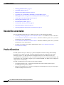
Product Overview
The PRE performs all Layer 2 and Layer 3 packet manipulation related to routing and forwarding
through the Cisco 10000 series ESR. Its advanced application-specific integrated circuit (ASIC)
technology supports very high performance throughput with IP services enabled on each port.
The PRE runs Cisco IOS Release 12.0(S). It contains two PCM/CIA slots, 32 MB of Flash memory, and
a packet buffer of up to 256 MB. It supports up to 512 MB of SDRAM. Two PREs can be configured in
a single chassis for redundancy.
The PRE is implemented on two printed circuit board assemblies:
•
Forwarding path (FP) card—Contains the backplane interconnect and the parallel express
forwarding network processor (PXF).
•
Route processing (RP) card—Contains the configuration and management route processing engine.
The RP card plugs into the FP card.
Cisco 10000 Series Router Performance Routing Engine Installation
2
OL-3971-03
Product Overview
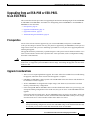
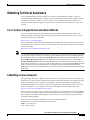
Figure 1
Distributed Processing Architecture in the PRE
Performance routing engine
Route
processor
PXF
network
processor
Forwarding engine
ASICs
Packet
buffers
33359
Backplane ASIC
Line
card
Line
card
Line
card
Redundant PREs
You can configure two PREs in a single chassis for redundancy. If the primary PRE fails, the secondary
PRE automatically takes over operation of the router. Because all the line cards are physically connected
to both the primary and secondary PREs, the failure of a single PRE does not require user intervention.
If a failure occurs, all line cards automatically reset to the redundant PRE.
With redundant PREs, the Cisco 10000 series ESR can survive even a catastrophic processor failure and
still maintain the highest levels of uptime and availability. Startup and running configurations of the
secondary PRE are synchronized with the primary PRE, ensuring the fastest possible cut-over time if the
primary PRE fails.
Forwarding Path
The Cisco 10000 series ESR forwarding path comprises a unique blend of hardware and microcoded
processors that yields high forwarding rates with considerable flexibility for future growth in packet
processing features.
The forwarding path is centered around a pair of Cisco-designed multiprocessor ASICs called parallel
express forwarding (PXF) network processors. Each PXF network processor provides a packet
processing pipeline consisting of 16 microcoded processors, arranged as multiple pipelines.
Each of the 16 processors in a PXF network processor is an independent, high-performance processor,
customized for packet processing. Each processor, called an eXpress microcontroller (XMC), provides
a sophisticated dual-instruction-issue execution unit, with a variety of special instructions designed to
execute packet processing tasks efficiently.
In addition to processing packets, XMCs have access to on-chip resources such as register files and
timers. They also have shared access to very large off-chip memories for storing state information, such
as routing tables and packet queues.
Within a single PXF network processor, the 16 XMCs are linked together in four parallel pipelines. Each
pipeline comprises four XMCs arranged as a systolic array, where each processor can efficiently pass its
results to its neighboring downstream processor. Four parallel pipelines are used, to increase throughput.
Cisco 10000 Series Router Performance Routing Engine Installation
OL-3971-03
3
Product Overview
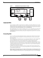
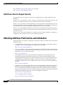
Within the Cisco 10000 series ESR, two PXF network processor ASICs are used, yielding four parallel
processing pipelines, each containing eight processors in a row.
Cisco 10000 Series ESR Forwarding Path Processor Array
PXF network
processor
Packets
in
PXF network
processor
XMC
XMC
XMC
XMC
XMC
XMC
XMC
XMC
XMC
XMC
XMC
XMC
XMC
XMC
XMC
XMC
XMC
XMC
XMC
XMC
XMC
XMC
XMC
X MC
XMC
XMC
XMC
XMC
XMC
XMC
XMC
XMC
Modified
packets
out
45275
Figure 2
In the array of processors in , hardware, microcode, and Cisco IOS software resources provide advanced,
high-touch feature processing on the Cisco 10000 series ESR. The allocation of features to XMCs in the
processor pipeline is flexible and continues to change as new features are added.
The PXF network processor architecture allows all 32 independent processors to work efficiently on
per-packet feature processing, yielding high throughput while still allowing substantial feature
processing.
By centralizing packet processing in the PRE, the Cisco 10000 series ESR architecture frees up space
on line cards, enabling high interface density, yet retaining the compact NEBS transmission equipment
form factor.
Route Processor
The second component of the PRE is the route processor (RP), a high-speed, conventional
microprocessor that has special interfaces to the forwarding path:
•
A high-speed direct memory access (DMA) channel that is sends packets back and forth between
the FP and the RP. Packets such as route updates that are not processed by the FP are sent through
this link to the RP. Similarly, the RP sends packets by passing them to the FP for transmission to
line cards.
•
The RP also has memory-mapped access to all of the state information used by the eXpress
microcontrollers (XMCs). The RP is responsible for configuring the tables and lists used by the
XMCs.
The RP also includes such standard Cisco IOS facilities as Flash memory, NVRAM for storing
configuration files, and Ethernet connections for network management. This familiar environment makes
possible a simple transition from existing Cisco IOS-based routers to the Cisco 10000 series ESR
platform.
Cisco 10000 Series Router Performance Routing Engine Installation
4
OL-3971-03
Product Overview
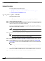
PRE Faceplates
The faceplates of the PRE, PRE-1, and PRE-2 are shown in this section.
Performance Routing Engine, Product Number ESR-PRE, Front Panel
OT
1
0
SL
ST
AT
US
FA
IL
R
MI
NO
IT
IC
AL
MA
JO
R
CR
AC
O
87348
OT
SL
ALARMS
AC
T
ET
IV
IT
Y
HE
R
LIN NE
T
K
PERFORMANCE ROUTING ENGINE
CISCO
10000
CO
AU
X
NS
OL
E
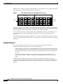
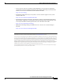
Figure 3
Figure 3 shows the front panel of the Performance Routing Engine, product number ESR-PRE.
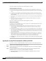
Performance Routing Engine, Product Number ESR-PRE1, Front Panel
ET
0
ST
AT
US
FA
IL
R
JO
NO
MI
IT
MA
CR
87430
1
SL
AC
O
IC
OT
ALARMS
OT
SL
R
AL
LIN
K
RN
IV
IT
Y
HE
AC
T
ET
AU
X
PERFORMANCE ROUTING ENGINE ESR-PRE1
CISCO
10000
CO
NS
O
LE
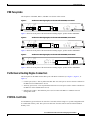
Figure 4
Figure 4 shows the front panel of the Performance Routing Engine, product number ESR-PRE1.
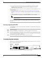
Performance Routing Engine, Product Number ESR-PRE2, Front Panel
76995
ST
AT
US
FA
IL
R
NO
AC
O
AL
R
IC
JO
IT
MA
CR
MI
IV
IT
Y
HE
RN
LIN
ET
K
ET
AC
T
AU
X
PERFORMANCE ROUTING ENGINE ESR-PRE2
ALARMS
CISCO
10000
CO
NS
OL
E
Figure 5
1
SL
OT
0
Figure 5 shows the front panel of the Performance Routing Engine, product number ESR-PRE2.
Performance Routing Engine Connectors
The front panel on the PRE contains three ports with RJ-45 connectors (see Figure 3, Figure 4, or
Figure 5):
•
Console port (CON)—This asynchronous EIA/TIA-232 serial port is used to connect a terminal to
the PRE for local administrative access.
•
Auxiliary port (AUX)—This asynchronous EIA/TIA-232 serial port is used to connect a modem to
the PRE for remote administrative access.
•
Ethernet port (ETH)—This Ethernet port is used to connect the PRE to a 10BaseT network
management LAN.
PCMCIA Card Slots
Two PCMCIA Type II card slots can store the Cisco IOS software image or a system configuration file
on a Flash disk memory card. The system can also boot from the software stored on the Flash disk
memory card.
Cisco 10000 Series Router Performance Routing Engine Installation
OL-3971-03
5
Prerequisites and Preparation
LED Indicators and Switches
LEDs on the front panel of the PRE provide a visual indication showing the status of PRE operation. The
LEDs are separated into three categories: alarms, status, and failure.
•
Alarm LEDs—Indicate any critical, major, or minor alarms generated by the Cisco 10000 router.
Alarm relay contacts can be used to connect the router to an external visual or audio alarm system.
This feature enables any critical, major, or minor alarms generated by the router to activate the visual
or audible alarms. To disable an audible alarm, press the alarm cut-off (ACO) switch on the PRE
front panel (see Figure 3). Note that shutting off an audible alarm does not disable the alarm LEDs.
See the Cisco 10005 Hardware Installation Guide or the Cisco 10000 Series Router Hardware
Installation and Maintenance Guide for additional information about alarm connections.
•
STATUS LED—Indicates the operational status of the PRE.
•
FAIL LED—Indicates if the card is not functioning properly.
See Table 4 for a complete description of the PRE LEDs.
Prerequisites and Preparation
Before you perform any of the procedures in this guide, Cisco recommends that you:
•
Read the safety guidelines in the next section and review the electrical safety and ESD-prevention
guidelines as described in the hardware installation guide for your router.
•
Ensure that the software configuration meets the minimum requirements for the installation (see the
“Software Compatibility” section on page 7).
•
Ensure that you have all of the necessary tools and equipment before beginning the installation (see
the “Installation Guidelines” section on page 7).
•
Have a terminal console connected to the PRE to configure the PRE after it is installed.
•
Have access to the following documents (available online) during the installation:
– Cisco 10000 Series Router Hardware Installation and Maintenance Guide
– Cisco 10000 Series Router Troubleshooting Guide
– Technology of Edge Aggregation: Cisco 10000 Series Router
Safety Guidelines
Before you begin the PRE installation procedure, review the safety guidelines in this section to avoid
injuring yourself or damaging the equipment. Before you install, configure, or perform maintenance on
the router, you should also review the safety warnings listed in the Regulatory Compliance and Safety
Information for Cisco 10000 Series Routers document.
Safety Warnings
Safety warnings appear throughout this publication in procedures that, if performed incorrectly, may
harm you. A warning symbol precedes each warning statement. The following warning is an example of
a safety warning. It identifies the warning symbol and associates it with a bodily injury hazard.
Cisco 10000 Series Router Performance Routing Engine Installation
6
OL-3971-03
Software Compatibility
Warning
Note
This warning symbol means danger. You are in a situation that could cause bodily injury. Before you
work on any equipment, be aware of the hazards involved with electrical circuitry and be familiar
with standard practices for preventing accidents. To see translations of the warnings that appear in
this publication, refer to the Regulatory Compliance and Safety Information document that
accompanied this device. Statement 1071
If you need translations of the safety warning, see the Regulatory Compliance and Safety Information
for Cisco 10000 Series Routers document.
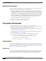
Software Compatibility
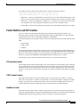
The ESR-PRE, ESR-PRE1, and ESR-PRE2 have specific Cisco IOS software requirements.
Table 2 shows the minimum required Cisco IOS software for each PRE.
Table 2
PRE Software Compatibility
PRE Product Number
Cisco IOS Software
Train
Minimum Cisco IOS Software release
ESR-PRE
12.0SL
Cisco IOS Release 12.0(9)SL1
ESR-PRE1
12.0SL
Cisco IOS Release 12.0(9)SL
12.0ST
Cisco IOS Release 12.0(20)ST
12.0SX
Cisco IOS Release 12.0(21)SX
12.2BX
Cisco IOS Release 12.2(15)BX
ESR-PRE2
1. The last (and latest) Cisco IOS software release to support the ESR-PRE is 12.0(20)ST
Use the show version command to display the system software version that is currently loaded and
running.
If the output of the show version command indicates that the Cisco IOS software is a version earlier than
the version identified as the minimum Cisco IOS software release in Table 2, check the contents of Flash
memory to determine if the required images are available on your system.
The output of the show flash command provides a list of all files stored in Flash memory. If the correct
software version is not installed, contact Cisco Customer Service (see the “Obtaining Technical
Assistance” section on page 43).
Installation Guidelines
This section contains guidelines for the following:
•
A new installation
•
A replacement installation
•
The required tools and equipment
Cisco 10000 Series Router Performance Routing Engine Installation
OL-3971-03
7
Installation Guidelines
The Cisco 10000 router is hot-swappable which means you can remove and replace a PRE while the
system is operating—if you have a secondary (redundant) PRE installed in the chassis. This feature
allows you to add, remove, or replace a PRE while the system maintains all routing information and
ensures session preservation.
Caution
Replacing the primary PRE in a non-redundant chassis (no secondary PRE) causes a system shutdown
and stops all traffic. If possible, alert all subscribers that the system will not be functioning during the
replacement.
Caution
To prevent electrostatic discharge (ESD) damage, handle the PRE by the faceplate or the card carrier
edges only. Avoid touching the printed circuit board and its components, or any connector pins.
New Installation Guidelines
If you are replacing the PRE in a non-redundant system, you must configure the PRE using the configure
command. For configuration information, refer to the “Configuring the PRE” section on page 16.
Replacement Installation Guidelines
If the PRE is replaced in a redundant system containing two PREs, the secondary (or newly installed)
PRE automatically assumes the configuration of the primary PRE; do not configure the new PRE.
Required Tools and Equipment
You need the following tools and equipment to install the PRE:
•
A 3/16-inch flat-blade screwdriver
•
An ESD-preventive wrist or ankle strap with connection cord
•
A terminal console to connect to the PRE after it is installed
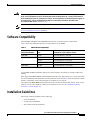
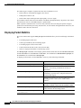
Removing the Cisco 10008 Front Cover
Use the following procedure to remove the front cover from the Cisco 10008 router.
•
If your Cisco 10008 router does not have a front bezel, go to the “Powering Off the System” section
on page 11.
•
If your Cisco 10008 router has a bezel with bezel plugs, go to step 1.
•
If your Cisco 10008 router has a bezel without bezel plugs, go to step 2.
Cisco 10000 Series Router Performance Routing Engine Installation
8
OL-3971-03
Installation Guidelines
Figure 6
Inserting a Screwdriver Blade Into a Bezel Latch
FANS OK
FAN FAILURE
MULTI-FAN FAILURE
Cisco 10000
30038
POWER
FAULT
MISWIRE
POWER POWER
FAULT FAULT
MISWIRE MISWIRE
Figure 7
Unlocking the Bezel Latch
FANS OK
FAN FAILURE
MULTI-FAN FAILURE
Cisco 10000
POWER POWER
FAULT FAULT
MISWIRE MISWIRE
Step 1
30039
POWER
FAULT
MISWIRE
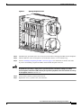
Unlock each bezel latch by inserting the tip of a flat-blade screwdriver between the top and bottom
sections of the latch (Figure 6), and then rotating the screwdriver to unlock the top portion of the latch
(Figure 7).
Repeat this procedure for all four bezel latches and then remove the latches.
Cisco 10000 Series Router Performance Routing Engine Installation
OL-3971-03
9
Installation Guidelines
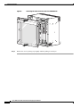
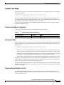
Figure 8
Removing the Front Cover from the Cisco 10008 Router
FANS
OK
FAN
FAILURE
MULTIFAN
FAILURE
When hot CAUTION
removal swapping
this fan
be done and replaceme
tray,
system in under two nt must
shutdown
minut
will occures or
.
FANS
OK
FAN FAI
LURE
MULTIFAN FAI
LURE
1
2
CISCO
10000
3
FA
CISCO
10000
4
Cisco 10
0A
PROC
ESSO
000
FA
IL
CISCO
10000
0B
R ONLY
CISCO
10000
IL
FA
IL
FA
IL
CISCO
10000
5
CISCO
10000
6
CISCO
10000
7
N
IL
SO
C
LE
CISCO
10000
FA
IL
O
8
CISCO
10000
FA
IL
FA
CISCO
10000
C
FA
O
CA
N
LE
AU
X
OP
LO
M
AR
AL R
IE
RR
OP
LO
M
CA
AR
AL R
IE
RR
0
IL
SO
AU
X
0
AC
TI
TY
ET
0
OP
LO
M
N
K
AR
AL R
IE
RR
OT
SL
ER
N
OP
LO
M
TY
H
LI
CA
ET
AR
AL R
IE
RR
K
1
OT
SL
0
1
OT
SL
0
OT
SL
VI
ET
N
N
CA
TI
ER
LI
OP
LO
M
AR
AL R
IE
RR
AC
H
1
CA
VI
ET
1
0
0
2
1
2
1
POWER
1
FAULT
MISWIRE
3
2
2
3
CA
LIN
2
OP
LO
RX
K
M
AR
AL
R
IE
TX
RR
POWE
R
FAULT
MISWIR
E
4
3
4
3
3
CA
5
4
RX
R
4
TX
IE
RR
4
5
5
5
5
R
IT
A
L
JO
R
IN
O
R
O
C
R
IT
IC
A
M
L
A
JO
R
M
IN
O
TA
TU
S
FA
6XCT3–DS0
S
6XCT3–DS0
R
6XCT3–DS0
S
TA
TU
IL
S
FA
IL
PROC
ESSO
R ONLY
Step 2
30040
POWE
R
FAULT
MISWIR
E
AC
OC–12/STM–4 POS SM–IR
6XCT3–DS0
IC
A
M
PERFORMANCE ROUTING ENGINE
O
C
M
FAULT
MISWIRE
PERFORMANCE ROUTING ENGINE
AC
6XCT3–DS0
CH OC-12-DSO SM-IR
GIGABIT ETHERNET
POWER
Remove the cover by lifting it up slightly and then pulling it toward you.
Cisco 10000 Series Router Performance Routing Engine Installation
10
OL-3971-03
Installation Guidelines
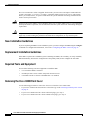
Powering Off the System
If you are installing or replacing a system with a single PRE, you must power down the system.
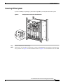
Figure 9
Setting DC Power Switch to the Off Position
FANS
OK
FAN
FAILUR
E
MULTI
FAN
FAILUR
E
When hot CAUTION
removal swapping
this fan
be done and replacement
tray,
must
system in under two
shutdo
wn will minutes or
occur.
1
2
CISCO
10000
3
CISCO
10000
4
0A
PROCES
SOR ONL0B
Y
FA
CISCO
10000
FA
IL
CISCO
10000
IL
FA
IL
FA
IL
CISCO
10000
5
6
CISCO
10000
CISCO
10000
8
CISCO
10000
IL
FA
IL
FA
IL
FA
CISCO
10000
IL
FA
CO
NS
OL
E
AU
X
OP
LO
M
AR
AL
IER
RR
CA
OP
LO
M
AR
AL
IER
RR
CA
0
7
CISCO
10000
CO
NS
OL
E
AU
X
0
0
OP
LO
M
AR
AL
IER
RR
CA
OP
LO
M
AR
AL
IER
RR
CA
1
OT
0
OT
SL
SL
AC
TI
VI
TY
ET
HE
RN
LI
NK
ET
OP
LO
M
AR
AL
IER
RR
CA
AC
TI
VI
TY
ET
HE
RN
LI
NK
ET
1
OT
0
OT
1
SL
SL
1
0
0
2
1
2
1
1
POWER
FAULT
MISWIRE
3
2
M
OP
IER
AR
2
LO
RX
K
AL
TX
RR
CA
LIN
2
3
4
3
4
3
3
CA
5
RR
4
5
RX
4
TX
IER
4
5
5
5
R
IT
AL
O
R
IN
O
R
O
R
IT
IC
AL
M
AJ
O
R
M
IN
O
S
FA
6XCT3–DS0
U
6XCT3–DS0
R
ST
AT
6XCT3–DS0
FAULT
MISWIR
E
AC
C
OC–12/STM–4 POS SM–IR
6XCT3–DS0
IC
AJ
M
PERFORMANCE ROUTING ENGINE
O
C
M
FAULT
MISWIRE
PERFORMANCE ROUTING ENGINE
AC
6XCT3–DS0
POWER
CH OC-12-DSO SM-IR
GIGABIT ETHERNET
POWER
ST
AT
IL
U
S
FA
IL
PROCES
30019
SOR ONL
Y
Step 1
Remove the front cover if necessary.
Step 2
Set the power switch to the off (0) position. If you have redundant PEMs, set both power switches to the
off (0) position. See Figure 9 for the DC PEM switch. See Figure 10 for an illustration of the AC PEM.
Cisco 10000 Series Router Performance Routing Engine Installation
OL-3971-03
11
Installing or Replacing the PRE
Figure 10
Setting AC Power Switch to the Off Position
FANS
OK
FAN
FAILUR
E
MULTI
FAN
FAILUR
E
When hot CAUTION
removal swapping
this fan
be done and replacement
tray,
must
system in under two
shutdo
wn will minutes or
occur.
1
2
CISCO
10000
3
CISCO
10000
4
0A
PROCES
SOR ON 0B
LY
FA
CISCO
10000
FA
IL
CISCO
10000
IL
FA
IL
FA
IL
CISCO
10000
5
CISCO
10000
6
CISCO
10000
7
OP
LO
M
AR
AL
IER
RR
CA
IL
FA
CO
E
CISCO
10000
IL
FA
NS
OL
8
CISCO
10000
IL
FA
IL
FA
CISCO
10000
CO
NS
OL
AU
OP
LO
M
AR
AL
IER
RR
CA
0
E
X
AU
X
0
AC
TI
TY
AC
NK
TY
ET
ET
HE
SL
RN
1
OT
SL
0
OT
LI
NK
ET
0
OP
LO
M
AR
AL
IER
RR
CA
1
OT
SL
0
OT
SL
VI
RN
LI
OP
LO
M
AR
AL
IER
RR
CA
TI
HE
1
OP
LO
M
AR
AL
IER
RR
CA
VI
ET
1
0
0
2
1
2
1
POWER
1
FAULT
3
2
CA
2
OP
LO
RX
M
AR
AL
IER
TX
RR
K
LIN
2
3
4
3
4
3
3
4
5
4
RX
4
TX
IER
RR
CA
5
5
5
5
O
C
R
M
IT
AJ
IN
IC
O
O
AL
R
R
S
IT
AJ
IN
IC
O
O
AL
R
R
6XCT3–DS0
U
M
6XCT3–DS0
FA
O
R
M
6XCT3–DS0
ST
AT
AC
C
OC–12/STM–4 POS SM–IR
6XCT3–DS0
M
PERFORMANCE ROUTING ENGINE
AC
FAULT
PERFORMANCE ROUTING ENGINE
POWER
6XCT3–DS0
FAULT
CH OC-12-DSO SM-IR
GIGABIT ETHERNET
POWER
ST
AT
IL
U
FA
S
IL
PROCES
SOR ON
30026
LY
Go to “Removing a PRE” section on page 17 or “Installing a PRE” section on page 13.
Installing or Replacing the PRE
This section describes how to install or replace the PRE in the Cisco 10000 chassis. It contains the
following procedures:
•
Installing a PRE, page 13
•
Configuring the PRE, page 16
•
Removing a PRE, page 17
Also see the “Troubleshooting the Installation” section on page 29.
Cisco 10000 Series Router Performance Routing Engine Installation
12
OL-3971-03
Installing or Replacing the PRE
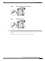
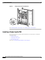
Installing a PRE
Use the following procedure to install the PRE into slot 0A or slot 0B in the Cisco 10000 chassis.
Note
If you are replacing a PRE, see the “Removing a PRE” section on page 17 before you begin this
procedure.
Figure 11
ESD Chassis Connection
5
5
5
5
CISCO
10000
5
IT
IC
A
L
A
JO
R
M
O
R
C
R
IT
IC
A
M
L
A
JO
R
M
IN
O
TA
TU
S
FA
6XCT3–DS0
S
6XCT3–DS0
R
6XCT3–DS0
FAULT
MISWIR
E
AC
O
OC–12/STM–4 POS SM–IR
IN
PERFORMANCE ROUTING ENGINE
R
M
PERFORMANCE ROUTING ENGINE
C
6XCT3–DS0
6XCT3–DS0
CH OC-12-DSO SM-IR
POWER
AC
O
S
TA
TU
IL
S
FA
IL
PROC
ESSO
1
1
Step 1
126144
R ONLY
ESD socket
Attach an antistatic wrist strap to your wrist and to an ESD socket on the chassis, or to a bare metal
surface on the chassis or frame.
Cisco 10000 Series Router Performance Routing Engine Installation
OL-3971-03
13
Installing or Replacing the PRE
Figure 12
Inserting the PRE
FANS
OK
FAN
FAILURE
MULTIFAN
FAILURE
When hot CAUTION
removal swapping
this fan
be done and replacem
tray,
system in under two ent must
shutdow
minu
n will occutes or
r.
1
2
CISCO
10000
3
4
0A
PROC
ESSO
0B
R ONLY
CISCO
10000
5
6
CISCO
10000
FA
IL
FA
IL
FA
CISCO
10000
FA
IL
CISCO
10000
IL
CISCO
10000
FA
8
CISCO
10000
FA
IL
CISCO
10000
7
CISCO
10000
FA
IL
CISCO
10000
IL
C
FA
O
N
O
OP
LO
M
AR
AL R
RIE
CAR
LE
OP
LO
M
AR
AL R
RIE
CAR
O
IL
S
0
C
N
AU
X
0
S
O
TIV
IT
E
Y
TH
E
LIN RN
E
K
T
X
1
OT
SL
0
OT
SL
1
1
TIV
IT
Y
TH
E
LIN RN
E
K
T
0
OP
LO
M
AR
AL R
RIE
CAR
AU
AC
OP
LO
M
AR
AL R
RIE
CAR
AC
OP
LO
M
AR
AL R
RIE
CAR
LE
0
0
E
1
OT
SL
0
OT
SL
1
2
1
2
POWER
FAULT
MISWIR
E
1
2
3
2
OP
LO
RX
M
AR
AL
R
IE
TX
RR
NK
CA
LI
2
3
3
4
3
4
3
CAR
4
5
RX
R
4
TX
RIE
4
5
5
5
5
JO
R
IN
O
R
IC
A
L
JO
R
O
R
6XCT3–DS0
A
M
IT
IN
OC–12/STM–4 POS SM–IR
L
A
M
6XCT3–DS0
A
R
M
6XCT3–DS0
IC
O
C
PERFORMANCE ROUTING ENGINE
IT
M
AC
6XCT3–DS0
R
6XCT3–DS0
O
C
PERFORMANCE ROUTING ENGINE
FAULT
MISWIR
E
AC
CH OC-12-DSO SM-IR
GIGABIT ETHERNET
POWER
S
TA
TU
S
FA
IL
S
TA
TU
FA
S
PROC
ESSO
R ONLY
32682
IL
Step 2
Grasp the faceplate of the PRE with one hand and place your other hand under the module (to support
the weight of the module). Position the PRE in front of the chassis slot.
Step 3
Carefully align the upper and lower edges of the PRE with the upper and lower guides in the chassis, and
slide the PRE into the slot until you can feel it begin to seat in the backplane connectors.
Cisco 10000 Series Router Performance Routing Engine Installation
14
OL-3971-03
Installing or Replacing the PRE
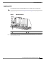
Figure 13
Closing the Ejector Levers
FANS
OK
FAN
FAILURE
MULTIFAN
FAILURE
When hot CAUTION
removal swapping
this fan
be done and replaceme
tray,
system in under two nt must
shutdown
minu
will occutes or
r.
1
2
CISCO
10000
3
4
0A
PROC
ESSO
0B
R ONLY
CISCO
10000
FA
IL
FA
CISCO
10000
CISCO
10000
IL
FA
IL
FA
IL
CISCO
10000
5
CISCO
10000
CISCO
C1
10000 0000
PRE
6
CISCO
10000
7
O
N
O
IL
S
C
LE
FA
O
CA
N
O
O
LE
AU
CA
M
OP
N
X
OP
LO
M
AR
AL R
IE
RR
LO
AR
AL R
IE
RR
C
IL
S
0
S
AU
O
X
0
LE
AC
IT
C
O
N
S
O
LE
M
X
OP
0
T
AU
LO
AR
AL R
IE
RR
E
CA
1
OT
0
OT
N
K
M
0
R
N
OP
SL
E
LI
LO
T
AR
AL R
IE
RR
Y
TH
E
CA
K
M
N
IT
E
N
OP
R
LO
TIV
E
SL
1
OT
SL
0
OT
1
AR
AL R
IE
RR
SL
1
AC
Y
TH
CA
TIV
E
LI
CISCO
10000
CISCO
10000
FA
IL
C
8
CISCO
10000
FA
IL
FA
CISCO
10000
0
AU
2
1
2
1
1
AC
TI
3
V
2
3
4
3
Y
TH
1
OT
SL
0
OT
SL
OP
LO
RX
M
AR
AL
R
IE
TX
RR
NK
2
4
IT
E
2
3
CA
LI
POWER
FAULT
MISWIR
E
X
E
R
LI
N
N
E
K
T
3
CA
5
4
RX
R
4
TX
IE
RR
4
5
5
5
5
IT
IC
A
L
A
JO
R
M
O
R
AC
O
C
R
IT
IC
A
M
L
A
JO
R
M
O
TA
TU
S
FA
TA
TU
6XCT3–DS0
S
S
6XCT3–DS0
R
6XCT3–DS0
IN
OC–12/STM–4 POS SM–IR
IN
PERFORMANCE ROUTING ENGINE
R
M
FAULT
MISWIR
E
PERFORMANCE ROUTING ENGINE
C
6XCT3–DS0
6XCT3–DS0
CH OC-12-DSO SM-IR
GIGABIT ETHERNET
POWER
AC
O
S
FA
S
TA
TU
IL
S
FA
IL
S
TA
TU
IL
S
FA
IL
R ONLY
PROC
ESSOR
Step 4
ONLY
32683
PROC
ESSO
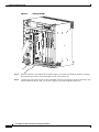
Simultaneously pivot both ejector levers toward each other (until they are parallel to the faceplate) to
firmly seat the PRE in the backplane.
The PRE cycles through its power-on self-test. The Fail LED stays on briefly (10 to 15 seconds) and then
shuts off. If the Fail LED remains on, go to the “Troubleshooting the Installation” section on page 29
Step 5
Caution
Check the captive screw that fastens the cover on the PCMCIA slot.
If you do not screw down the cover of the PCMCIA slot on the PRE, the open cover exposes the unit to
the risk of a harmful ESD event, and might cause electromagnetic interference (EMI) above the
prescribed levels.
Cisco 10000 Series Router Performance Routing Engine Installation
OL-3971-03
15
Installing or Replacing the PRE
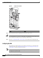
Figure 14
Captive Screw Locations
FANS
OK
FAN
FAILURE
MULTIFAN
FAILURE
When hot CAUTION
removal swapping
this fan
be done and replacem
tray,
system in under two ent must
shutdow
minu
n will occutes or
r.
1
2
CISCO
C10
000
100
00
1GE
3
4
CISCO
C10
000
100
6CT00
3
FA
IL
IL
FAIL
1
CISCO
10000
FA
IL
FAIL
0A
PROC
ESSO
R
CISCO
C10
000
100
6CT00
3
FA
IL
FA
CISCO
C10
000
10000
ChC
O12
FAIL
FAIL
C
O
N
S
O
LE
P
AU
OP
LO
M
AR
AL R
RIE
CAR
OP
LO
M
AR
AL R
RIE
CAR
M
0 CA ALARLOO
PORT
0
0
PORT
0
X
M
CA ALARLOOP
AC
TIV
E
Y
TH
E
LIN RN
E
K
T
1
PORT
1
T
SLO
1
T
SLO
0
T
SLO
1
PORT
1
IT
0
2 2
PORT
2 2
PORT
PORT
3 3
R
AR
M
M
CA ALAR OP
LO
TX
OP
LINK
LO
RIE
RX
AL
TX
NK
PORT
3 3
CAR
LI
POWER
FAULT
MISWIR
E
RX
PORT
4 4
PORT
4 4
PORT
5 5
PORT
5 5
C
R
IT
6XCT3–DS0
IC
A
M
L
A
JO
R
M
IN
O
R
POWER
FAULT
MISWIR
E
PERFORMANCE ROUTING ENGINE
O
6XCT3–DS0
CH OC-12-DSO SM-IR
GIGABIT ETHERNET
AC
S
TA
TU
S
FA
IL
R
1
Step 6
Caution
Step 7
1
132833
PROC
ESSO
Captive screws
Secure the PRE in the chassis by tightening the top and bottom captive screws.
To ensure that there is adequate space for additional line cards, always tighten the captive screws on each
newly installed PRE before you insert a secondary PRE or any additional line cards. The captive screws
prevent accidental removal and provide proper grounding for EMI shielding.
Refer to the “Configuring the PRE” section on page 16 for information about configuring the PRE.
Configuring the PRE
After the PRE is successfully installed, you can configure it for network use. For information about
configuring the PRE, see the “Managing the Router Using the Network Management Ethernet Port”
section on page 31, and other sections in this document.
Note
You do not need to configure a redundant (secondary) PRE. The secondary PRE automatically assumes
the configuration of the primary PRE.
Cisco 10000 Series Router Performance Routing Engine Installation
16
OL-3971-03
Installing or Replacing the PRE
Removing a PRE
Use the following procedure to remove a PRE from the chassis:
Figure 15
ESD Chassis Connection
5
5
5
5
CISCO
10000
5
IT
IC
A
L
A
JO
R
M
O
R
C
R
IT
IC
A
M
L
A
JO
R
M
IN
O
TA
TU
S
FA
6XCT3–DS0
S
6XCT3–DS0
R
6XCT3–DS0
FAULT
MISWIR
E
AC
O
OC–12/STM–4 POS SM–IR
IN
PERFORMANCE ROUTING ENGINE
R
M
PERFORMANCE ROUTING ENGINE
C
6XCT3–DS0
6XCT3–DS0
CH OC-12-DSO SM-IR
POWER
AC
O
S
TA
TU
IL
S
FA
IL
PROC
ESSO
1
1
Step 1
126144
R ONLY
ESD socket
Attach an antistatic wrist strap to your wrist and to the ESD socket on the chassis, or to a bare metal
surface on the chassis or frame.
Cisco 10000 Series Router Performance Routing Engine Installation
OL-3971-03
17
Installing or Replacing the PRE
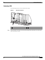
Figure 16
Captive Screw Locations
FANS
OK
FAN
FAILURE
MULTIFAN
FAILURE
When hot CAUTION
removal swapping
this fan
be done and replacem
tray,
system in under two ent must
shutdow
minu
n will occutes or
r.
1
2
CISCO
C10
000
100
00
1GE
3
4
CISCO
C10
000
100
6CT00
3
FA
IL
IL
FAIL
1
CISCO
10000
FA
IL
FAIL
0A
PROC
ESSO
R
CISCO
C10
000
100
6CT00
3
FA
IL
FA
CISCO
C10
000
10000
ChC
O12
FAIL
FAIL
C
O
N
S
O
LE
P
AU
OP
LO
M
AR
AL R
RIE
CAR
OP
LO
M
AR
AL R
RIE
CAR
M
0 CA ALARLOO
PORT
0
0
PORT
0
X
M
CA ALARLOOP
AC
TIV
E
Y
TH
E
LIN RN
E
K
T
1
PORT
1
T
SLO
1
T
SLO
0
T
SLO
1
PORT
1
IT
0
2 2
PORT
2 2
PORT
PORT
3 3
R
AR
M
M
CA ALAR OP
LO
TX
OP
LINK
LO
RIE
RX
AL
TX
NK
PORT
3 3
CAR
LI
POWER
FAULT
MISWIR
E
RX
PORT
4 4
PORT
4 4
PORT
5 5
PORT
5 5
C
R
IT
6XCT3–DS0
IC
A
M
L
A
JO
R
M
IN
O
R
POWER
FAULT
MISWIR
E
PERFORMANCE ROUTING ENGINE
O
6XCT3–DS0
CH OC-12-DSO SM-IR
GIGABIT ETHERNET
AC
S
TA
TU
S
FA
IL
R
1
Step 2
1
132833
PROC
ESSO
Captive screws
Loosen the top and bottom captive screws on the PRE.
Cisco 10000 Series Router Performance Routing Engine Installation
18
OL-3971-03
Installing or Replacing the PRE
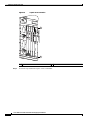
Figure 17
Opening the Ejector Levers
FANS
OK
FAN
FAILURE
MULTIFAN
FAILURE
When hot CAUTION
removal swapping
this fan
be done and replaceme
tray,
system in under two nt must
shutdown
minu
will occutes or
r.
1
2
CISCO
10000
3
4
CISCO
10000
FA
IL
FA
CISCO
10000
0A
PROC
ESSO
0B
R ONLY
CISCO
10000
IL
FA
IL
FA
IL
CISCO
10000
5
CISCO
10000
CISCO
C1
10000 0000
PRE
6
CISCO
10000
7
O
N
O
IL
S
C
LE
CISCO
10000
FA
IL
C
FA
O
CA
N
IL
S
C
LE
AU
CA
O
X
LO
M
OP
N
M
AU
OP
AR
AL R
IE
RR
LO
AR
AL R
IE
RR
O
0
S
X
0
O
IT
O
N
S
LE
AU
LO
M
X
OP
AR
AL R
IE
RR
0
T
O
CA
M
E
OP
N
K
LO
0
R
N
AR
AL R
IE
RR
E
LI
CA
T
M
Y
TH
E
OP
K
IT
E
N
LO
R
1
OT
SL
0
OT
SL
1
TIV
E
N
AR
AL R
IE
RR
1
OT
SL
0
OT
SL
1
AC
Y
TH
CA
TIV
E
C
LE
AC
LI
CISCO
10000
8
CISCO
10000
FA
IL
FA
CISCO
10000
0
AU
2
1
2
1
1
AC
T
3
ETHIVIT
2
E
3
3
3
4
E
T
RX
R
4
TX
IE
RR
4
5
K
CA
5
N
IN
O
SL
0
OT
SL
4
E
LN
L K R
1
OT
SL
0
OT
SL
OP
4
Y
TH
2
LO
RX
M
AR
AL
R
IE
TX
RR
NK
2
3
CA
LI
POWER
FAULT
MISWIR
E
X
5
5
5
IT
IC
A
L
A
JO
R
M
O
R
O
C
R
IT
IC
A
M
L
A
JO
R
M
IN
O
TA
TU
FA
S
TA
TU
6XCT3–DS0
S
S
6XCT3–DS0
R
6XCT3–DS0
FAULT
MISWIR
E
AC
OC–12/STM–4 POS SM–IR
IN
PERFORMANCE ROUTING ENGINE
R
M
PERFORMANCE ROUTING ENGINE
C
6XCT3–DS0
6XCT3–DS0
CH OC-12-DSO SM-IR
GIGABIT ETHERNET
POWER
AC
O
S
S
FA
TA
TU
IL
S
FA
IL
S
TA
TU
IL
S
FA
IL
R ONLY
PROC
ESSOR
ONLY
32680
PROC
ESSO
Step 3
Simultaneously pivot both ejector levers away from each other to disengage the PRE from the backplane.
Step 4
Slide the PRE out of the slot and place it on an antistatic surface, or in an antistatic bag.
Step 5
See the “Installing or Replacing the PRE” section on page 12 for instructions to install a new PRE.
If you are not installing a replacement PRE, install a blank faceplate in the slot.
Warning
Do not operate the system unless all slots contain a PRE, line card, or a blank faceplate. Blank
faceplates are necessary in empty slots to prevent exposure to hazardous voltages, to reduce
electromagnetic interference (EMI) that may disrupt other equipment, and to direct the flow of cooling
air through the chassis. Statement 156
Step 6
Power on the system if you have powered it off.
Step 7
Replace the cover, if you have one, and removed it.
Cisco 10000 Series Router Performance Routing Engine Installation
OL-3971-03
19
Managing PRE Redundancy
Managing PRE Redundancy
This section explains how to manage redundant PRE failover methods.
Synchronizing PRE Configurations
You do not need to specify redundancy between PREs. If two PREs are installed in the Cisco 10000
series router, they automatically act as a redundant pair.
In the default state, redundant PREs are configured to automatically synchronize all critical files. You
can use the auto-sync command to specify which files should be synchronized.
Step 1
Select the redundancy configuration submode.
Router(config)# redundancy
Step 2
Select the main-cpu configuration submode.
Router(config-r)# main-cpu
Step 3
Specify which file or files should be autosynchronized. For example:
Router(config-r-mc)# auto-sync startup-config
Any configuration options entered in the main-cpu submode act only on the primary PRE, not on the
secondary PRE.
The following lists the options for the auto-sync command:
auto-sync [startup-config | running-config | bootvar | config-register | standard]
[no] auto-sync [startup-config | running-config | bootvar | config-register | standard]
Where:
•
startup-config instructs the PREs to synchronize the startup configuration files.
Use the no form of the command to turn off startup configuration synchronization.
•
running-config instructs the PREs to synchronize the running configuration files.
Use the no form of the command to turn off running-config synchronization.
•
bootvar instructs the PREs to synchronize the boot variables.
Use the no form of the command to turn off boot variables synchronization.
•
config-register instructs the PREs to synchronize the configuration register values.
Use the no form of the command to turn off config-register synchronization.
•
standard instructs the PREs to synchronize all of the above.
Use the no form of the command to turn off all of the above auto-synchronization features.
The default for the auto-sync command is auto-sync standard.
Cisco 10000 Series Router Performance Routing Engine Installation
20
OL-3971-03
Upgrading Software
Forcing Failover in a Redundant Pair
To manually force the primary and secondary devices in a redundant pair to failover, use the redundancy
force-failover command. Manually force the primary and secondary PREs to reverse roles if you need
to replace the primary one. You can then replace the PRE while causing only minimal disruption of
traffic.
Router# redundancy force-failover main-cpu
This command does not generate an alarm as a hardware reset does.
The following example shows how to set the secondary PRE to be active:
Router# redundancy force-failover main-cpu
Upgrading Software
This section describes methods for upgrading Cisco IOS images on the Cisco 10000 series router.
Upgrading Software on a Single PRE
To upgrade software for a single PRE, follow these steps:
Step 1
Copy the IOS image from a TFTP server to the Flash disk in slot 0.
Router# copy tftp disk0:
Address or name of remote host [172.31.53.64]?
Source filename [c10000/c10k-p6-mz]?
c10000/c10k-p6-mz
Accessing
tftp://172.31.53.64/c10000/c10k-p6-mz
.
Loading c10000/c10k-p6-mz from
172.31.53.64 (via FastEthernet0/0/0):
!!!!!!!!!!!!!!!!!!!!!!!!!!!!!!!!!!!!!!!!!!!!!!!!!!!!!!!!!!!!!!!!!!!!!!...
[OK - 5717476/11433984 bytes]
5717476 bytes copied in 250.840 secs (22869 bytes/sec)
Router#
Step 2
Tell the Cisco 10000 series router the location in which the new boot image resides. In the following
example, the system is told that the image “c10k-p6-mz” is located on disk 0:
Router(config)# boot system flash disk0:c10k-p6-mz
Step 3
Copy the running configuration to the startup configuration.
Router# copy running-config startup-config
Step 4
Reload the software by entering the reload command.
Router# reload
The system is now using the new Cisco IOS image.
Cisco 10000 Series Router Performance Routing Engine Installation
OL-3971-03
21
Managing System Boot Parameters
Upgrading Software on Redundant PREs
This section tells you how to upgrade software on redundant PREs. For the procedure described here to
work, PRE redundancy should be configured as auto-sync standard (the default). See the
“Synchronizing PRE Configurations” section on page 20.
Step 1
Copy the IOS image from a TFTP server to the Flash disk in slot 0.
Router# copy tftp disk0:
Address or name of remote host [172.31.53.64]?
Source filename [c10000/c10k-p6-mz]?
c10000/c10k-p6-mz
Accessing
tftp://172.31.53.64/c10000/c10k-p6-mz
.
Loading c10000/c10k-p6-mz from
172.31.53.64 (via FastEthernet0/0/0):
!!!!!!!!!!!!!!!!!!!!!!!!!!!!!!!!!!!!!!!!!!!!!!!!!!!!!!!!!!!!!!!!!!!!!!...
[OK - 5717476/11433984 bytes]
5717476 bytes copied in 250.840 secs (22869 bytes/sec)
Router#
Step 2
Copy the same image to the secondary PRE Flash disk in slot 0.
Router# copy tftp sec-disk0:
The output is the same as that shown in Step 1.
Step 3
Tell the Cisco 10000 router the location in which the new boot image resides. In the following example,
the system is told that the image “c10k-p6-mz” is located on disk 0:
Router(config)# boot system flash disk0:c10k-p6-mz
Step 4
Copy the running configuration to the startup configuration.
Router# copy running-config startup-config
Step 5
Reset the secondary PRE so that it reboots and uses the new image.
Router# hw-module sec-cpu reset
Step 6
Force a cutover to the secondary PRE, which forces the primary PRE to reboot and use the new image.
Router# redundancy force-failover main-cpu
Both PREs are now running the new Cisco IOS image.
Managing System Boot Parameters
This section tells you how to use IOS to modify PRE boot parameters.
During the boot process, the system reads a software configuration register that defines certain system
parameters. The software configuration register is a 16-bit register in NVRAM used to define such
characteristics as:
•
The source of the Cisco IOS software image required to run the router
•
Whether the system software should ignore the contents of NVRAM
Cisco 10000 Series Router Performance Routing Engine Installation
22
OL-3971-03
Managing System Boot Parameters
•
The behavior of the Break function
By modifying the boot parameters, you can customize your Cisco 10000 series router. For example, a
common configuration register setting in some lab environments is 0x2100. Using this setting, the
system boots to the ROM monitor prompt, where a technician can load a specific image by entering the
boot command at the rommon prompt. (For more information, see the Cisco IOS Configuration
Fundamentals Configuration Guide.)
Changing the Software Configuration Register Settings
To change the software configuration register settings while you are running system software, perform
the following steps:
Step 1
From global configuration mode, enter the config-register value command to set the contents of the
software configuration register; value is a hexadecimal number preceded by 0x. For example:
Router(config)# config-register 0x2100
Consult the hexadecimal column in Table 3 for the possible settings to enter as the 4-bit value parameter.
Step 2
Exit global configuration mode by pressing Ctrl-Z.
Router(config)# Ctrl-Z
Router#
The new contents of the software configuration register are saved to NVRAM. These new settings do not
take effect until you reload the system or reboot the router.
Step 3
To display the new software configuration register setting, issue the show version command.
Router# show version
.
.
.
#Configuration register is 0x141 (will be 0x2100 at next reload)
Step 4
Save the configuration file to preserve the new software configuration register settings.
Router# copy running-config startup-config
Step 5
Reboot the router.
The software configuration register setting takes affect only after you reload the system. This happens
when you issue the reload command from the console or reboot the router.
Configuration Register Settings
Table 3 summarizes the modifications that you can make to the software configuration register. For
detailed information, refer to the Cisco IOS Configuration Fundamentals Command Reference.
Note
The factory default value for the software configuration register is 0x2102. This value is a combination
of the following: binary bit 8 = 0x0100, bits 00 through 03 = 0x0002, and bit 13 = 2000.
Cisco 10000 Series Router Performance Routing Engine Installation
OL-3971-03
23
Managing System Boot Parameters
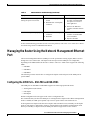
Table 3
Definition of Bits in the Software Configuration Register
Bit No.
Hex Value
Meaning/Function
00 to 03
0x0000 to 0x000F
Defines the source of a default Cisco IOS software image required to run the router:
•
00—At power-on, the system remains at the ROM monitor prompt (rommon>),
awaiting a user command to boot the system manually by means of the rommon
boot command.
•
01—At power-on, the system automatically boots the first system image found in
the Flash memory single inline memory module (SIMM) on the PRE.
•
02 to 0F—At power-on, the system automatically boots from a default Cisco IOS
software image stored on a TFTP server in the network. For this setting, the Fast
Ethernet port on the PRE must be configured and operational. This setting also
enables boot system commands that override the default filename.
06
0x0040
Causes system software to ignore the contents of NVRAM.
07
0x0080
Enable the original equipment manufacturer (OEM) bit.
08
0x0100
The Break function is disabled after 30 seconds.
09
0x0200
Not used.
10
0x0400
Broadcast based on 0.0.0.0 IP address.
11 and 12
0x0800 to 0x1000
Defines the console baud rate (the default setting is 9600 baud).
13
0x2000
Boots an image from the Flash SIMM.
14
0x4000
Broadcast using the subnet broadcast address.
15
0x8000
Enables diagnostic messages and ignores the contents of NVRAM.
Cisco 10000 Series Router Performance Routing Engine Installation
24
OL-3971-03
Upgrading from an ESR-PRE or ESR-PRE1 to an ESR-PRE2
Upgrading from an ESR-PRE or ESR-PRE1
to an ESR-PRE2
This section describes the procedures for upgrading the Performance Routing Engine from an ESR-PRE
or ESR-PRE1 to an ESR-PRE2. Procedures for downgrading from an ESR-PRE2 to an ESR-PRE1 or
ESR-PRE are also described.
•
Prerequisites, page 25
•
Upgrade Considerations, page 25
•
Upgrade Procedures, page 26
•
Troubleshooting the Installation, page 29
Prerequisites
For all of the software features supported by your current ESR-PRE (c10k-p6-mz) or ESR-PRE1
(c10k-p10-mz) image to function correctly, they must be supported by the ESR-PRE2 (c10k2-p11-mz)
image. Please check with your Cisco marketing representative to verify the correct upgrade path before
initiating the upgrade.
The upgrade should be performed by a qualified engineer. This person must be familiar with the Cisco
router console interface and be able to perform basic router operations, such as configuration loading
and router reload functions.
Caution
Do not perform this upgrade if your current ESR-PRE or ESR-PRE1 software image supports new
features not yet supported by the ESR-PRE2 software image. Performing this upgrade will cause these
features to fail.
Upgrade Considerations
•
This is a service impacting hardware upgrade. The router will not be available for user traffic during
the upgrade, and traffic cannot resume until the upgrade is complete.
•
ESR-PREs or ESR-PRE1s cannot operate with an ESR-PRE2 in the same chassis and should never
be installed in a chassis together.
•
All new ESR-PRE2s are shipped with a helper image (c10k-eboot-mz) stored in the boot flash
memory, and without any configuration.
•
If the existing ESR-PRE or ESR-PRE1 has a removable flash-based media card, you can copy your
startup and running configuration to the media card, and you can use it on the ESR-PRE2 after the
upgrade.
If the media card has enough space, the new ESR-PRE2 image can also be copied there, which will
save time later on. If you desire to do this, download the latest ESR-PRE2 (c10k2-p11-mz) image
from the TFTP server to the removable media card in disk0/1 or slot0/1.
Note
If you have redundant PREs installed in the Cisco 10000 chassis, and you intend to save the
startup and running configuration, and the new ESR-PRE2 image to the flash-based media card,
be sure that you save them to both flash-based media cards on both PREs.
Cisco 10000 Series Router Performance Routing Engine Installation
OL-3971-03
25
Upgrading from an ESR-PRE or ESR-PRE1 to an ESR-PRE2
Upgrade Procedures
This section contains several upgrade procedures:
•
Upgrading the Primary PRE to an ESR-PRE2, page 26
•
Upgrading the Secondary PRE of a Redundant Pair of PREs to an ESR-PRE2, page 28
•
Reversing an Upgrade to an ESR-PRE2, page 29
Upgrading the Primary PRE to an ESR-PRE2
Follow this procedure to upgrade:
•
A single PRE in a Cisco 10000 chassis that does not have a redundant, secondary PRE.
•
The primary PRE in a Cisco 10000 chassis that has a redundant pair of PREs installed.
Step 1
Connect a terminal to the primary PRE.
Step 2
Save the startup and running configuration to a location on a TFTP server, or to a flash-based media card
(flash-disk or flash-memory) on the ESR-PRE or ESR-PRE1.
If you save to a flash-based media card, and you have a redundant pair of ESR-PREs or ESR-PRE1s
installed in the chassis, be sure that you save the startup and running configuration to both flash-based
media cards on both ESR-PREs or ESR-PRE1s.
Caution
Step 3
When the ESR-PRE or ESR-PRE1 is removed from the chassis, any local configuration will
be lost. You must save your configuration.
Power down the router. All the traffic on the router is terminated.
Note
PREs can be hot-swapped. However, since removing a PRE terminates all traffic, we recommend
that you power down the router to ensure a successful installation.
Step 4
Remove the ESR-PRE or ESR-PRE1 (or both PREs in a redundant configuration) from the chassis by
following the procedure in the “Removing a PRE” section on page 17.
Step 5
Insert the ESR-PRE2 into slot A of the chassis by following the procedure in the “Installing a PRE”
section on page 13. If you have a second, redundant ESR-PRE2 to install, set it aside for installation later
in this procedure.
Note
Although a PRE can be installed in slot B, to ensure proper operation, we recommend that you
install a single, non-redundant PRE in slot A.
Step 6
If you saved the startup and running configuration to a flash-based media card in Step 2, remove the flash
media from the ESR-PRE or ESR-PRE1 and insert it into the ESR-PRE2. Otherwise, proceed to step 7.
Step 7
Power up the router. The router boots up in read-only memory (ROM) monitor mode.
Cisco 10000 Series Router Performance Routing Engine Installation
26
OL-3971-03
Upgrading from an ESR-PRE or ESR-PRE1 to an ESR-PRE2
Note
Step 8
The config-register of a new ESR-PRE2 (shipped from the factory) is set to 0x0. If your
ESR-PRE2 is not new from the factory, and the config-register is not set to 0x0, it may behave
differently while booting up.
From the console in ROM monitor mode, enter the appropriate boot command, depending on whether
you saved the ESR-PRE2 image to a TFTP server or a flash-based media card, or whether you did not
save the ESR-PRE2 image.
Booting from a TFTP Server
If you saved the ESR-PRE2 image on a TFTP server that is reachable from the router (for example, if
the router and server are on the same LAN or there is a default proxy server), boot the router from the
TFTP server.
In the following example, the router boots the ESR-PRE2 (c10k2-p11-mz) image from a network server
with the IP address 172.16.15.112:
> boot tftp://172.16.15.112/c10k2-p11-mz
The configuration dialog appears.
You can now proceed to step 9.
Booting from a Flash-Based Media Card
If the image was saved to the flash-based media card, boot that image.
The following boot command loads the ESR-PRE2 image from the media card:
> boot system flash disk0:c10k2-p11-mz
The configuration dialog appears.
You can now proceed to step 9.
Booting from the Helper Image
If you did not save the ESR-PRE2 image to either a TFTP server or a flash-based media card, boot the
helper (c10k-eboot-mz) image, which is shipped with the ESR-PRE2 boot flash memory.
In the following example, the router boots from the helper image:
> boot c10k-eboot-mz
The configuration dialog appears.
Proceed to the “Did Not Save the Configuration” section on page 28.
Step 9
Restore the startup and running configuration of the router, depending on whether you saved the
ESR-PRE2 image to a TFTP server or a flash-based media card, or you did not save the ESR-PRE2
image.
Saved the Configuration on a Flash-Based Media Card
If you booted the c10k2-p11-mz image, and you saved the previous configuration to a flash-based media
card:
a.
Exit the configuration dialog and restore the previously saved startup and running configuration
from the media card.
b.
Update any boot commands to use the new ESR-PRE2 (c10k2-p11-mz) image.
Cisco 10000 Series Router Performance Routing Engine Installation
OL-3971-03
27
Upgrading from an ESR-PRE or ESR-PRE1 to an ESR-PRE2
The router is available for normal operations and the upgrade is complete.
Saved the Configuration on a TFTP Server
If you booted the c10k2-p11-mz image, and you saved the previous configuration to a TFTP server:
a.
Enter the initial configuration dialog, and enter all required information to allow access to the TFTP
server.
b.
Assign the correct IP address for the Fast Ethernet interface to become active and for the TFTP
server to become reachable. This may require adding an IP route for the server even after the initial
dialog completes.
c.
Restore the previous configuration from the TFTP server to the startup and running configuration on
the router.
d.
Restore the startup and running configuration and update any boot commands to use the new
ESR-PRE2 (c10k2-p11-mz) image.
The router is available for normal operations and the upgrade is complete.
Did Not Save the Configuration
If you did not save the ESR-PRE2 image to either a TFTP server or a flash-based media card, and you
booted the helper (c10k-eboot-mz) image:
a.
Enter the initial configuration dialog, and enter all required information. Be sure to assign the
correct IP address for the Fast Ethernet interface to become active and for the TFTP server to
become reachable.
b.
The TFTP server should be reachable. If you wish to boot the ESR-PRE2 image from a local media
device, download the ESR-PRE2 (c10k2-p11-mz) image from the TFTP server to the local media
device (bootflash, disk0/1, or slot0/0). If you wish to boot directly from the TFTP server, you can
skip the image download.
c.
Restore the previously saved configuration by downloading it from the TFTP server. Update any
boot commands from the previous configuration to point to the new ESR-PRE2 (c10k2-p11-mz)
image. Otherwise, update the boot command to point to the desired ESR-PRE2 image.
d.
Reload the router. After reload, the router is available to resume normal operations and the upgrade
is complete.
Upgrading the Secondary PRE of a Redundant Pair of PREs to an ESR-PRE2
If you have a secondary, redundant ESR-PRE2 to install in the chassis, use the following procedure:
Step 1
Insert the second, redundant ESR-PRE2 into chassis slot B.
Step 2
Connect the terminal to the console port of the ESR-PRE2 in slot B. The console displays the ROM
monitor mode prompt (>).
Step 3
If you have a flash-based media card that contains the startup and running configuration and the
ESR-PRE2 image from your previous redundant ESR-PRE or ESR-PRE1:
a.
Remove the flash-based media card from that ESR-PRE or ESR-PRE1 and insert it into the
ESR-PRE2 in slot B.
Cisco 10000 Series Router Performance Routing Engine Installation
28
OL-3971-03
Upgrading from an ESR-PRE or ESR-PRE1 to an ESR-PRE2
b.
Boot the image from the flash-based media card in the ESR-PRE2 in slot B. The redundant
ESR-PRE2 in slot B comes up as the secondary PRE, and the configuration synchronizes
automatically between the two PREs.
If you do not have any removable media devices, then you upgrade this redundant ESR-PRE2 as if it was
a single ESR-PRE2:
a.
Remove the ESR-PRE2 from slot A and go to Step 7 of the “Upgrading the Primary PRE to an
ESR-PRE2” section on page 26. Follow the single board upgrade procedures for the ESR-PRE2 in
slot B.
b.
Insert the ESR-PRE2 back into slot A. This redundant ESR-PRE2 in slot A now comes up as the
secondary PRE, and the configuration is synchronized automatically between the PREs.
Note
If you desire the primary ESR-PRE2 to be in slot A, you can perform a switchover from the
console at this point.
The redundant ESR-PRE2 upgrade is now complete, and the router is available to resume normal
operations.
Reversing an Upgrade to an ESR-PRE2
Use the following procedure to reinstall an ESR-PRE or ESR-PRE1 (or redundant PREs) after upgrading
to an ESR-PRE2.
Step 1
Power down the router.
Step 2
Remove the ESR-PRE2 (or both ESR-PRE2s in a redundant configuration) from the chassis.
Step 3
Insert the original ESR-PRE(s) or ESR-PRE1(s) back into the chassis. If you swapped flash-based media
cards to the ESR-PRE2(s) during the upgrade, remove them from the ESR-PRE2(s) and insert them back
into the appropriate ESR-PRE(s) or ESR-PRE1(s).
Step 4
Power on the router. The router loads as it originally did before the upgrade.
Troubleshooting the Installation
Refer to Table 4 for descriptions of the LEDs on the PRE. Follow the instructions in Table 5 on the next
page to troubleshoot the installation.
PRE-1 LEDs
0
ST
AT
US
FA
IL
NO
R
R
JO
IT
IC
MA
CR
87430
1
AC
O
AL
OT
SL
ALARMS
OT
SL
MI
IV
IT
Y
HE
R
LIN NE
T
K
AC
T
ET
AU
X
PERFORMANCE ROUTING ENGINE ESR-PRE1
CISCO
10000
CO
NS
OL
E
Figure 18
See Figure 3 and Figure 5 for illustrations of the PRE and PRE-2 faceplates.
Cisco 10000 Series Router Performance Routing Engine Installation
OL-3971-03
29
Upgrading from an ESR-PRE or ESR-PRE1 to an ESR-PRE2
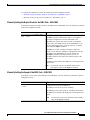
Table 4
PRE LED Status and Descriptions
LED
Status
Description
LED
Status
Description
Ethernet port:
ACTIVITY
Green
Packets are being transmitted and received.
Off
No activity.
Ethernet port: LINK
Green
Carrier detected, the port is able to pass traffic.
Off
No carrier detected, the port is not able to pass traffic.
PCMCIA slot 0
Green
Slot 0 is active.
PCMCIA slot 1
Green
Slot 1 is active.
Critical, major, and
minor LEDs
Off
No alarm.
Yellow
Indicates and alarm condition
Alarm cutoff (ACO)
switch
—
Pressing this switch disables an audible alarm.
STATUS
Flashing yellow
System is booting.
Green
PRE is active (primary).
Flashing green
PRE is standby (secondary)
Off
No power to PRE.
Yellow
Amajor failure has disable the PRE.
Off
The PRE is operating correctly.
FAIL
Table 5
PRE Installation Troubleshooting
Symptom
Power entry modules (PEMs),
fans, and other line cards do not
operate
Possible Cause
1.
Disconnected power cord.
2.
Power switch is in the Off
position.
3.
The PRE fuses are blown.
Corrective Action
1.
Check that all power cords
are properly connected to
both the Cisco 10000
chassis and at the power
connection end.
2.
Set the PEM power
switches to the On
position.
3.
Replace the PRE.
Cisco 10000 Series Router Performance Routing Engine Installation
30
OL-3971-03
Managing the Router Using the Network Management Ethernet Port
Table 5
PRE Installation Troubleshooting (continued)
Symptom
The Fail LED does not light
during the power-on self-test
PRE does not operate properly
Possible Cause
1.
The PRE is not properly
seated.
2.
Bad PRE slot or backplane
connector.
1.
Bad PRE slot or backplane
connector.
2.
Bad PRE.
Corrective Action
1.
Be sure the ejector levers
are fully closed and that
the captive screws have
been tightened.
2.
Remove the PRE and
install it in another chassis
slot.
1.
Remove the PRE and
install it in another PRE
slot if available.
2.
Replace the PRE.
If these troubleshooting procedures do not correct the problem, refer to the Cisco 10000 Series Router
Troubleshooting Guide for additional information.
Managing the Router Using the Network Management Ethernet
Port
The network management Ethernet (NME) port on the performance routing engine (PRE) is used to
manage the Cisco 10000 router. The duplex mode and speed of the NME port are configurable,
depending on the PRE installed in the router’s chassis. The Cisco 10000 router supports the following
PREs:
•
ESR-PRE
•
ESR-PRE1
•
ESR-PRE2
The following sections describe how to configure the duplex mode and speed of the NME port for
specific PREs.
Configuring the NME Port—ESR-PRE and ESR-PRE1
The NME port for ESR-PRE or ESR-PRE1 supports the following operational modes:
•
Autonegotiation (the default)
•
Full-duplex
•
Half-duplex
Default configurations do not appear in the router’s configuration file.
We recommend that you allow the NME port to autonegotiate the duplex mode. When autonegotiation
mode is enabled, the NME port responds only to 802.3x pause frames from another device.
If the negotiation of duplex mode fails and a duplex mode mismatch occurs, manually set the duplex
mode for full-duplex or half-duplex operation. Setting duplex mode disables autonegotiation mode.
When you manually set duplex mode, the NME port does not support 802.3x flow control.
Cisco 10000 Series Router Performance Routing Engine Installation
OL-3971-03
31
Managing the Router Using the Network Management Ethernet Port
When you manually configure duplex mode, the NME port can experience problems such as flapping. If
this occurs, disable duplex mode by entering the no full-duplex or no half-duplex command. When you
enter the no duplex command, the operational mode reverts to autonegotiation mode.
To configure the NME port, perform the following optional configuration tasks:
•
Manually Setting the Duplex Mode for the NME Port—ESR-PRE or ESR-PRE1, page 32
•
Manually Setting the Speed for the NME Port—ESR-PRE or ESR-PRE1, page 32
Manually Setting the Duplex Mode for the NME Port—ESR-PRE or ESR-PRE1
Note
We recommend that you allow the NME port to autonegotiate (default setting) duplex mode.
To manually set the duplex operational mode of the NME port for ESR-PRE or ESR-PRE1, enter either
of the following commands in interface configuration mode:
Command
Purpose
Router(config-if)# full-duplex
Configures the NME port for full-duplex operational mode.
For ESR-PRE1, the full-duplex command appears in the router’s
configuration file. If the configuration file does not specify a
duplex mode, half-duplex mode is implied.
Note
Router(config-if)# half-duplex
To return the system to its default duplex mode
(autonegotiation), enter the no duplex command.
Configures the NME port for half-duplex operational mode.
For ESR-PRE1, the half-duplex command does not appear in the
router’s configuration file, but it is implied.
Note
To return the system to its default duplex mode
(autonegotiation), enter the no duplex command.
Manually Setting the Speed for the NME Port—ESR-PRE or ESR-PRE1
The Cisco IOS software automatically negotiates the speed of the NME port for ESR-PRE or ESR-PRE1.
You cannot manually set the speed of the NME port.
Configuring the NME Port—ESR-PRE2
The NME port for ESR-PRE2 supports the following operational modes:
•
Autonegotiation
•
Full-duplex (the default)
•
Half-duplex
The NME port defaults to 100 Mbps full-duplex mode. Default configurations do not appear in the
configuration file.
Cisco 10000 Series Router Performance Routing Engine Installation
32
OL-3971-03
Managing the Router Using the Network Management Ethernet Port
To configure the NME port, perform the following optional configuration tasks:
•
Manually Setting the Duplex Mode for the NME Port—ESR-PRE2, page 33
•
Manually Setting the Speed of the NME Port—ESR-PRE2, page 33
Manually Setting the Duplex Mode for the NME Port—ESR-PRE2
To manually configure the duplex mode of the NME port for ESR-PRE2, enter the following command
in interface configuration mode:
Command
Purpose
Router(config-if)# duplex {half |
full | auto}
Configures the duplex operation mode for the NME port.
The half keyword sets half-duplex mode. If you migrate a
half-duplex configuration from the ESR-PRE1 to the
ESR-PRE2, the system resets duplex mode to full-duplex
because that is the default setting for the ESR-PRE2. If you
still want half-duplex mode, you must explicitly set duplex
mode using the duplex command.
The full keyword sets 100 Mbps full-duplex mode (the
default). If you migrate a full-duplex configuration from the
ESR-PRE1 to the ESR-PRE2, the system discards the
full-duplex command, but duplex mode is still set to
full-duplex mode because that is the default setting for the
ESR-PRE2.
The auto keyword enables the NME port to autonegotiate the
duplex mode.
Note
To return the system to its default duplex mode
(full-duplex), enter the no duplex command.
Manually Setting the Speed of the NME Port—ESR-PRE2
To manually set the speed of the NME port for ESR-PRE2, enter the following command in interface
configuration mode:
Command
Purpose
Router(config-if)# speed {10 | 100
| auto}
Configures the speed of the NME port.
The 10 keyword sets the speed for 10 Mbps.
The 100 keyword sets the speed for 100 Mbps (the default).
The auto keyword enables the NME port to autonegotiate the
speed.
Note
To return the system to its default speed (100 Mbps),
enter the no speed command.
Cisco 10000 Series Router Performance Routing Engine Installation
OL-3971-03
33
Analyzing and Troubleshooting Packets
Analyzing and Troubleshooting Packets
The Parallel eXpress Forwarding (PXF) engine of the Performance Routing Engine (PRE) is responsible
for processing and forwarding packets. As processing occurs, PXF counters increment to reflect the
internal behavior of the PRE. The router collects this statistical information from the counters and
appropriately displays it when you enter specific show pxf cpu commands. The output from these
commands is useful in analyzing and troubleshooting denied and logged packets.
To correctly interpret packet statistics, it is important that you understand the behavior of the router
during packet and access list processing, and the counters that provide the statistical data. This section
briefly describes access list processing, some PXF counters and their behavior, and some of the
commands you can use to display statistical information. This section is based on ESR-PRE2 with
differences noted for ESR-PRE and ESR-PRE1.
Access Control Lists
The Cisco 10000 series router provides traffic filtering capabilities using access control lists (ACLs).
Access lists filter network traffic by controlling whether routed packets are forwarded or blocked at the
router's interfaces. Using ACLs, you can do such things as restrict the contents of routing updates,
provide traffic flow control, and provide security for your network.
The Cisco 10000 series router supports the following ACL types and features:
•
Standard and extended ACLs
•
Named and numbered ACLs
•
Turbo-ACLs
•
Per-user ACLs
•
IP receive ACLs
•
Time-based ACLs
The access-list command is used to configure an ACL. For example, the following configuration creates
ACL 108:
access-list 108 permit udp any host 10.68.1.10 range 0 5000 log
access-list 108 permit udp host 10.1.1.10 range 0 5000 any log
After creating an ACL, it is applied to an interface using the ip access-group command. The router
executes the ACL from top to bottom, denying or permitting packets as directed by the access-list entries
(ACEs). When the log keyword is specified in an ACE, the router sends packet information to the
console.
The last line of an ACL is an implicit deny statement that appears to the router as:
deny any any
This statement causes the router to deny any packets remaining after processing the ACEs of the access
list. The implicit deny statement does not include the log keyword; therefore, the router does not send
packet information to the console for those packets denied by the implicit deny statement.
Cisco 10000 Series Router Performance Routing Engine Installation
34
OL-3971-03
Analyzing and Troubleshooting Packets
For example, the router processes the following ACL from top to bottom as follows:
access-list 108 permit udp any host 10.68.1.10 range 0 5000 log
access-list 108 permit udp host 10.1.1.10 range 0 5000 any log
•
Statement 1—Allows any UDP packet to access host 10.68.1.10 if the UDP destination port of the
packet is between 0 and 5000. The router logs packet information to the console if a match is made.
•
Statement 2—Allows any UDP packet from host 10.1.1.10 with a source port between 0 and 5000
to be permitted. The router logs packet information to the console if a match is made.
•
Implicit Deny—Denies all remaining packets and does not log the packet information to the console.
Packet Statistics and PXF Counters
The Cisco 10000 router Performance Routing Engine (PRE) provides high performance Layer 3
processing using its Parallel eXpress Forwarding (PXF) engine and Route Processor (RP). The PRE
installed in the chassis can be a ESR-PRE, ESR-PRE1, or ESR-PRE2.
As the PXF engine processes packets, counters such as the following reflect the internal operation of the
PRE:
•
IP forwarding
•
ICMP created
•
Feedback
The statistical information that the PXF counters provide is useful in analyzing and troubleshooting
denied and logged packets. Because the internal operation of the ESR-PRE/ESR-PRE1 and ESR-PRE2
differs for ACLs, the PXF counters are inconsistent between the PREs. However, system-wide router
behavior is consistent for ESR-PRE1 and ESR-PRE2 despite the differences in counters.
The following sections describe the PXF counters and the way in which they increment.
IP Forwarding Counter
A forwarding information base (FIB) lookup is one of the initial steps in forwarding a packet. When the
router forwarding processor needs information to forward a packet, it performs a lookup operation on
the FIB table. The IP forwarding counter reflects the state of that lookup operation. It does not reflect
whether or not the packet was forwarded. This counter increments each time a FIB lookup successfully
occurs.
ICMP Created Counters
Some FIB lookup operations can cause ICMP messages to be generated. For example, if a packet’s
time-to-live (TTL) expires, an address is unreachable, or an ACL-denied packet is dropped, an ICMP
message is generated. The ICMP created counters reflect the number of ICMP packets created. The
counters increment each time a FIB lookup results in the generation of an ICMP message.
Feedback Counter
Sometimes the PXF engine cannot complete the processing of a packet before the packet completes a
single pass through the PXF; the packet requires additional processing. As a result, the packet is fed back
through the PXF and processing continues. This is referred to as a feedback operation.
Cisco 10000 Series Router Performance Routing Engine Installation
OL-3971-03
35
Analyzing and Troubleshooting Packets
The following are examples of packets that can cause feedbacks to occur:
•
Packets that are forwarded and logged to the console
•
ICMP packets that are sent
•
Packets that require both input and output quality of service (QoS)
The feedback counter reflects the total number of feedbacks through the PXF by all packets. The counter
increments one time for each additional pass a packet makes.
When a packet is denied because of an ACL deny statement, the router drops the packet. Dropped
packets do not need further processing and, therefore, are not fed back through the PXF. In this case, the
feedback counter does not increment.
Displaying Packet Statistics
The Cisco 10000 router supports show pxf cpu commands that allow you to do such things as determine
the:
•
Forwarding engine traffic load
•
Traffic types handled by the forwarding engine
•
Forwarding engine actions on the traffic
•
Traffic load from the PXF to the route processor (RP)
•
Status of output packet buffers for the queuing system
The show pxf cpu commands used to display packet statistics differ between the ESR-PRE/ESR-PRE1
and the ESR-PRE2. For the ESR-PRE or ESR-PRE1, the commands are show hardware pxf cpu; for
the ESR-PRE2, the commands are show pxf cpu.
To display packet statistics for the ESR-PRE2, enter any of the following commands:
Command
Purpose
Router# show running-config
Displays the current router configuration.
Router# show version
Displays information about the currently loaded
software version along with hardware and device
information.
Router# show pxf cpu statistics security
Displays information about packets denied and
permitted by a specific ACL, and packets denied or
permitted and logged.
Router# show pxf cpu drop
Displays drop statistics for the forwarding processor,
including packets counts for the ICMP created
counters.
Router# show pxf cpu context
Displays forwarding processor context statistics,
including feedback counts from the feedback counter.
Router# show pxf cpu statistics ip
Displays forwarding IP statistics, including forwarded
counts from the IP forwarding counter.
Router# show interfaces type
slot/module/port
Displays information about an interface.
Cisco 10000 Series Router Performance Routing Engine Installation
36
OL-3971-03
Analyzing and Troubleshooting Packets
Sample Case Study
For the purposes of this case study, assume that the following ACL is configured on the router’s outbound
serial 1/0/0 interface:
access-list 108 permit udp any host 10.68.1.10 range 0 5000 log
access-list 108 permit udp host 10.1.1.l0 range 0 5000 any log
A traffic simulator is used to send 100 UDP packets to the Cisco 10000 router with the source and
destination ports of the packets set to 6000. Packets arrive on the Gigabit Ethernet 2/0/0 interface and
are supposed to leave the router through the serial 1/0/0 interface.
After processing the 100 UDP packets, the show pxf cpu commands are entered to display statistical
information about the packets.
Hardware and Software Components
Table 6 lists the hardware and software components used in the case study.
Table 6
Hardware and Software Components
Cisco IOS Release
Processor
Image
Experimental version 12.0
ESR-PRE2
c10k-p8-mz.weekly.03272002
Filtering the Traffic
On the outbound serial 1/0/0 interface, the Cisco 10000 router filters the 100 packets sent by the traffic
simulator using the ACL applied to the interface. The router executes the ACL from top to bottom in the
following way:
access-list 108 permit udp any host 10.68.1.10 range 0 5000 log
access-list 108 permit udp host 10.1.1.10 range 0 5000 any log
•
Statement 1—Allows any UDP packet to access host 10.68.1.10 if the UDP destination port of the
packet is between 0 and 5000. The router logs packet information to the console if a match is made.
•
Statement 2—Allows any UDP packet from host 10.1.1.10 with a source port between 0 and 5000
to be permitted. The router logs packet information to the console if a match is made.
•
Implicit Deny—Denies all remaining packets and does not log the packet information to the console.
Remember, the 100 UDP packets were sent with a source and destination port of 6000. As the router
executes the ACL, none of the 100 packets matches ACL statements 1 and 2 because of the different port
numbers. The router then executes the implicit deny statement.
The implicit deny statement terminates any ACL. This statement tells the router to deny all other traffic.
Because the 100 packets did not match statements 1 and 2, the router then executes the deny all statement
and denies the packets.
Displaying Packet Statistics for ACLs
The show pxf cpu statistics security command provides statistical information about the packets
denied, permitted, and logged by ACLs. The router collects statistics for mini-compiled ACLs, but not
for turbo-compiled ACLs.
Cisco 10000 Series Router Performance Routing Engine Installation
OL-3971-03
37
Analyzing and Troubleshooting Packets
The following example output provides packet information before sending the 100 packets. Notice that
the Packets Denied field indicates that no packets have been denied by ACL 108. The Denied and Log
field indicates that no denied packets have been logged.
Router# show pxf cpu statistics security
ACL PktsPktsDeniedPermit
NameDeniedPermitted& Log& Log
108 0
0
0
0
The following example output results after sending the 100 packets. Notice that the Packets Denied field
now indicates that 100 packets have been denied. Recall that the router denied the packets because they
matched the implicit deny statement. This statement does not include a log keyword, which causes
information to be sent to the console. Therefore, no logging occurs. Notice that the Denied and Log field
correctly indicates this.
Router# show pxf cpu statistics security
ACL PktsPktsDeniedPermit
NameDeniedPermitted& Log& Log
108 100 0
0
0
Displaying IP Forwarding Statistics
The show pxf cpu statistics ip command provides statistical information about IP forwarding. The
following example output indicates the count of the IP forwarding counter before sending the 100
packets. Notice that the count is 402.
Router# show pxf cpu statistics ip
FP ip statistics
dropped0
forwarded402
punted540
input_packets942
icmps_created 0
noadjacency0
noroute0
unicast_rpf0
.
.
.
The following example output results after sending the 100 packets. Notice that the IP forwarding
counter is now 502.
Router# show pxf cpu statistics ip
FP ip statistics
dropped0
forwarded502 /*incremented by 100*/
punted540
input_packets942
icmps_created0
noadjacency0
noroute0
unicast_rpf0
.
.
.
Cisco 10000 Series Router Performance Routing Engine Installation
38
OL-3971-03
Analyzing and Troubleshooting Packets
Displaying Drop Statistics
The show pxf cpu statistics drop command provides information about dropped packets and ICMP
packets. The following example output indicates the count of the icmp_unrch_interval counter before
sending the 100 packets. Notice that the count is zero.
Router# show pxf cpu statistics drop
FP drop statistics
packetsbytes
generic00
mpls_no_eos00
fib_zero_dest00
fib_drop_null00
fib_icmp_no_adj00
fib_icmp_bcast_dst00
mfib_ttl_000
mfib_disabled00
mfib_rpf_failed00
mfib_null_oif00
tfib_rp_flag00
tfib_eos_violation00
tfib_nonip_expose00
tfib_label_invalid00
tfib_path_unknown00
tfib_nonip_ttl_exp00
icmp_unrch_interval 0 0 /*no ICMP packets created*/
icmp_on_icmp00
icmp_bad_hdr00
icmp_multicast00
icmp_frag00
macr_bad_tag_num00
.
.
.
The following example output indicates the count of the icmp_unrch_interval counter after sending the
100 packets. Notice that the icmp_unrch_interval count now indicates 100 due to the dropped packets.
Router# show pxf cpu statistics drop
FP drop statistics
packetsbytes
generic00
mpls_no_eos00
fib_zero_dest00
fib_drop_null00
fib_icmp_no_adj00
fib_icmp_bcast_dst00
mfib_ttl_000
mfib_disabled00
mfib_rpf_failed00
mfib_null_oif00
tfib_rp_flag00
tfib_eos_violation00
tfib_nonip_expose00
tfib_label_invalid00
tfib_path_unknown00
tfib_nonip_ttl_exp00
icmp_unrch_interval 100 12276 /*incremented by 100*/
icmp_on_icmp00
icmp_bad_hdr00
icmp_multicast00
Cisco 10000 Series Router Performance Routing Engine Installation
OL-3971-03
39
Obtaining Documentation
icmp_frag00
macr_bad_tag_num00
.
.
.
Displaying Feedback Counts
The show pxf cpu context command provides statistical information about the number of feedbacks
occurring and new packets being processed. The following example output indicates the count of the
feedback counter before sending the 100 packets. Notice that the count is 1027 feedbacks.
Router# show pxf cpu context
FP context statisticscountrate
-----------------------------feed_back 1027 0 /*1027 feedbacks*/
new_work_from_lc43036343482
new_work_from_rp42953329421
new_work_from_replay00
null_context20253090451166352444
-------6352446
.
.
.
The following example output indicates the count of the feedback counter after sending the 100 packets.
Notice that the count is now 1028. The counter increments by 1 due to an ICMP message sent as a result
of the deny action.
Router# show pxf cpu context
FP context statisticscountrate
-----------------------------feed_back 1028 0 /*incremented by 1*/
new_work_from_lc43036345012
new_work_from_rp42953329981
new_work_from_replay00
null_context20256377977316362297
-------6362301
Obtaining Documentation
Cisco documentation and additional literature are available on Cisco.com. Cisco also provides several
ways to obtain technical assistance and other technical resources. These sections explain how to obtain
technical information from Cisco Systems.
Cisco.com
You can access the most current Cisco documentation at this URL:
http://www.cisco.com/techsupport
You can access the Cisco website at this URL:
http://www.cisco.com
Cisco 10000 Series Router Performance Routing Engine Installation
40
OL-3971-03
Documentation Feedback
You can access international Cisco websites at this URL:
http://www.cisco.com/public/countries_languages.shtml
Product Documentation DVD
Cisco documentation and additional literature are available in the Product Documentation DVD package,
which may have shipped with your product. The Product Documentation DVD is updated regularly and
may be more current than printed documentation.
The Product Documentation DVD is a comprehensive library of technical product documentation on
portable media. The DVD enables you to access multiple versions of hardware and software installation,
configuration, and command guides for Cisco products and to view technical documentation in HTML.
With the DVD, you have access to the same documentation that is found on the Cisco website without
being connected to the Internet. Certain products also have .pdf versions of the documentation available.
The Product Documentation DVD is available as a single unit or as a subscription. Registered Cisco.com
users (Cisco direct customers) can order a Product Documentation DVD (product number
DOC-DOCDVD=) from Cisco Marketplace at this URL:
http://www.cisco.com/go/marketplace/
Ordering Documentation
Beginning June 30, 2005, registered Cisco.com users may order Cisco documentation at the Product
Documentation Store in the Cisco Marketplace at this URL:
http://www.cisco.com/go/marketplace/
Nonregistered Cisco.com users can order technical documentation from 8:00 a.m. to 5:00 p.m.
(0800 to 1700) PDT by calling 1 866 463-3487 in the United States and Canada, or elsewhere by
calling 011 408 519-5055. You can also order documentation by e-mail at
[email protected] or by fax at 1 408 519-5001 in the United States and Canada,
or elsewhere at 011 408 519-5001.
Documentation Feedback
You can rate and provide feedback about Cisco technical documents by completing the online feedback
form that appears with the technical documents on Cisco.com.
You can send comments about Cisco documentation to [email protected].
You can submit comments by using the response card (if present) behind the front cover of your
document or by writing to the following address:
Cisco Systems
Attn: Customer Document Ordering
170 West Tasman Drive
San Jose, CA 95134-9883
We appreciate your comments.
Cisco 10000 Series Router Performance Routing Engine Installation
OL-3971-03
41
Cisco Product Security Overview
Cisco Product Security Overview
Cisco provides a free online Security Vulnerability Policy portal at this URL:
http://www.cisco.com/en/US/products/products_security_vulnerability_policy.html
From this site, you can perform these tasks:
•
Report security vulnerabilities in Cisco products.
•
Obtain assistance with security incidents that involve Cisco products.
•
Register to receive security information from Cisco.
A current list of security advisories and notices for Cisco products is available at this URL:
http://www.cisco.com/go/psirt
If you prefer to see advisories and notices as they are updated in real time, you can access a Product
Security Incident Response Team Really Simple Syndication (PSIRT RSS) feed from this URL:
http://www.cisco.com/en/US/products/products_psirt_rss_feed.html
Reporting Security Problems in Cisco Products
Cisco is committed to delivering secure products. We test our products internally before we release them,
and we strive to correct all vulnerabilities quickly. If you think that you might have identified a
vulnerability in a Cisco product, contact PSIRT:
•
Emergencies — [email protected]
An emergency is either a condition in which a system is under active attack or a condition for which
a severe and urgent security vulnerability should be reported. All other conditions are considered
nonemergencies.
•
Nonemergencies — [email protected]
In an emergency, you can also reach PSIRT by telephone:
Tip
•
1 877 228-7302
•
1 408 525-6532
We encourage you to use Pretty Good Privacy (PGP) or a compatible product to encrypt any sensitive
information that you send to Cisco. PSIRT can work from encrypted information that is compatible with
PGP versions 2.x through 8.x.
Never use a revoked or an expired encryption key. The correct public key to use in your correspondence
with PSIRT is the one linked in the Contact Summary section of the Security Vulnerability Policy page
at this URL:
http://www.cisco.com/en/US/products/products_security_vulnerability_policy.html
The link on this page has the current PGP key ID in use.
Cisco 10000 Series Router Performance Routing Engine Installation
42
OL-3971-03
Obtaining Technical Assistance
Obtaining Technical Assistance
Cisco Technical Support provides 24-hour-a-day award-winning technical assistance. The Cisco
Technical Support & Documentation website on Cisco.com features extensive online support resources.
In addition, if you have a valid Cisco service contract, Cisco Technical Assistance Center (TAC)
engineers provide telephone support. If you do not have a valid Cisco service contract, contact your
reseller.
Cisco Technical Support & Documentation Website
The Cisco Technical Support & Documentation website provides online documents and tools for
troubleshooting and resolving technical issues with Cisco products and technologies. The website is
available 24 hours a day, at this URL:
http://www.cisco.com/techsupport
Access to all tools on the Cisco Technical Support & Documentation website requires a Cisco.com user
ID and password. If you have a valid service contract but do not have a user ID or password, you can
register at this URL:
http://tools.cisco.com/RPF/register/register.do
Note
Use the Cisco Product Identification (CPI) tool to locate your product serial number before submitting
a web or phone request for service. You can access the CPI tool from the Cisco Technical Support &
Documentation website by clicking the Tools & Resources link under Documentation & Tools. Choose
Cisco Product Identification Tool from the Alphabetical Index drop-down list, or click the Cisco
Product Identification Tool link under Alerts & RMAs. The CPI tool offers three search options: by
product ID or model name; by tree view; or for certain products, by copying and pasting show command
output. Search results show an illustration of your product with the serial number label location
highlighted. Locate the serial number label on your product and record the information before placing a
service call.
Submitting a Service Request
Using the online TAC Service Request Tool is the fastest way to open S3 and S4 service requests. (S3
and S4 service requests are those in which your network is minimally impaired or for which you require
product information.) After you describe your situation, the TAC Service Request Tool provides
recommended solutions. If your issue is not resolved using the recommended resources, your service
request is assigned to a Cisco engineer. The TAC Service Request Tool is located at this URL:
http://www.cisco.com/techsupport/servicerequest
For S1 or S2 service requests or if you do not have Internet access, contact the Cisco TAC by telephone.
(S1 or S2 service requests are those in which your production network is down or severely degraded.)
Cisco engineers are assigned immediately to S1 and S2 service requests to help keep your business
operations running smoothly.
To open a service request by telephone, use one of the following numbers:
Asia-Pacific: +61 2 8446 7411 (Australia: 1 800 805 227)
EMEA: +32 2 704 55 55
USA: 1 800 553-2447
Cisco 10000 Series Router Performance Routing Engine Installation
OL-3971-03
43
Obtaining Additional Publications and Information
For a complete list of Cisco TAC contacts, go to this URL:
http://www.cisco.com/techsupport/contacts
Definitions of Service Request Severity
To ensure that all service requests are reported in a standard format, Cisco has established severity
definitions.
Severity 1 (S1)—Your network is “down,” or there is a critical impact to your business operations. You
and Cisco will commit all necessary resources around the clock to resolve the situation.
Severity 2 (S2)—Operation of an existing network is severely degraded, or significant aspects of your
business operation are negatively affected by inadequate performance of Cisco products. You and Cisco
will commit full-time resources during normal business hours to resolve the situation.
Severity 3 (S3)—Operational performance of your network is impaired, but most business operations
remain functional. You and Cisco will commit resources during normal business hours to restore service
to satisfactory levels.
Severity 4 (S4)—You require information or assistance with Cisco product capabilities, installation, or
configuration. There is little or no effect on your business operations.
Obtaining Additional Publications and Information
Information about Cisco products, technologies, and network solutions is available from various online
and printed sources.
•
Cisco Marketplace provides a variety of Cisco books, reference guides, documentation, and logo
merchandise. Visit Cisco Marketplace, the company store, at this URL:
http://www.cisco.com/go/marketplace/
•
Cisco Press publishes a wide range of general networking, training and certification titles. Both new
and experienced users will benefit from these publications. For current Cisco Press titles and other
information, go to Cisco Press at this URL:
http://www.ciscopress.com
•
Packet magazine is the Cisco Systems technical user magazine for maximizing Internet and
networking investments. Each quarter, Packet delivers coverage of the latest industry trends,
technology breakthroughs, and Cisco products and solutions, as well as network deployment and
troubleshooting tips, configuration examples, customer case studies, certification and training
information, and links to scores of in-depth online resources. You can access Packet magazine at
this URL:
http://www.cisco.com/packet
•
iQ Magazine is the quarterly publication from Cisco Systems designed to help growing companies
learn how they can use technology to increase revenue, streamline their business, and expand
services. The publication identifies the challenges facing these companies and the technologies to
help solve them, using real-world case studies and business strategies to help readers make sound
technology investment decisions. You can access iQ Magazine at this URL:
http://www.cisco.com/go/iqmagazine
or view the digital edition at this URL:
http://ciscoiq.texterity.com/ciscoiq/sample/
Cisco 10000 Series Router Performance Routing Engine Installation
44
OL-3971-03
Obtaining Additional Publications and Information
•
Internet Protocol Journal is a quarterly journal published by Cisco Systems for engineering
professionals involved in designing, developing, and operating public and private internets and
intranets. You can access the Internet Protocol Journal at this URL:
http://www.cisco.com/ipj
•
Networking products offered by Cisco Systems, as well as customer support services, can be
obtained at this URL:
http://www.cisco.com/en/US/products/index.html
•
Networking Professionals Connection is an interactive website for networking professionals to
share questions, suggestions, and information about networking products and technologies with
Cisco experts and other networking professionals. Join a discussion at this URL:
http://www.cisco.com/discuss/networking
•
World-class networking training is available from Cisco. You can view current offerings at
this URL:
http://www.cisco.com/en/US/learning/index.html
This document is to be used in conjunction with the documents listed in the “Related Documentation” section.
CCSP, CCVP, the Cisco Square Bridge logo, Follow Me Browsing, and StackWise are trademarks of Cisco Systems, Inc.; Changing the Way We Work,
Live, Play, and Learn, and iQuick Study are service marks of Cisco Systems, Inc.; and Access Registrar, Aironet, ASIST, BPX, Catalyst, CCDA, CCDP,
CCIE, CCIP, CCNA, CCNP, Cisco, the Cisco Certified Internetwork Expert logo, Cisco IOS, Cisco Press, Cisco Systems, Cisco Systems Capital, the
Cisco Systems logo, Cisco Unity, Empowering the Internet Generation, Enterprise/Solver, EtherChannel, EtherFast, EtherSwitch, Fast Step, FormShare,
GigaDrive, GigaStack, HomeLink, Internet Quotient, IOS, IP/TV, iQ Expertise, the iQ logo, iQ Net Readiness Scorecard, LightStream, Linksys,
MeetingPlace, MGX, the Networkers logo, Networking Academy, Network Registrar, Packet, PIX, Post-Routing, Pre-Routing, ProConnect, RateMUX,
ScriptShare, SlideCast, SMARTnet, StrataView Plus, TeleRouter, The Fastest Way to Increase Your Internet Quotient, and TransPath are registered
trademarks of Cisco Systems, Inc. and/or its affiliates in the United States and certain other countries.
All other trademarks mentioned in this document or Website are the property of their respective owners. The use of the word partner does not imply a
partnership relationship between Cisco and any other company. (0502R)
© 2005Cisco Systems, Inc. All rights reserved.
Cisco 10000 Series Router Performance Routing Engine Installation
OL-3971-03
45
Obtaining Additional Publications and Information
Cisco 10000 Series Router Performance Routing Engine Installation
46
OL-3971-03