1
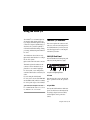
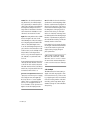
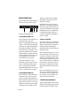
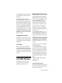
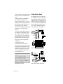
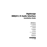
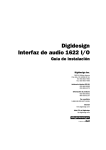
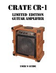
Digidesign
1622 I/O Audio Interface
Installation Guide
Digidesign Inc.
3401-A Hillview Avenue
Palo Alto, CA 94304 USA
tel: 650·842·7900
fax: 650·842·7999
Technical Support (USA)
650·842·6699
650·856·4275
Product Information
650·842·6602
800·333·2137
Fax on Demand
1-888-USE-DIGI (873-3444)
World Wide Web
www.digidesign.com
Digidesign FTP Site
ftp.digidesign.com
Copyright
Communications & Safety Regulation Information
This User’s Guide is copyrighted ©1999 by Digidesign, a
division of Avid Technology, Inc. (hereafter “Digidesign”), with
all rights reserved. Under copyright laws, this manual may not
be duplicated in whole or in part without the written consent of
Digidesign.
Compliance Statement
The model 1622 I/O complies with the following standards
regulating interference and EMC:
• FCC Part 15 Class A
• EN55103 – 1, environment E4
• EN55103 – 2, environment E4
• AS/NZS 3548 Class A
• CISPR 22 Class A
DIGIDESIGN, AVID and PRO TOOLS are trademarks or
registered trademarks of Digidesign and/or Avid Technology,
Inc. All other trademarks are the property of their respective
owners.
All features and specifications subject to change without
notice.
PN 932706988-00 REV A 9/99
Radio and Television Interference
This equipment has been tested and found to comply with the
limits for a Class A digital device, pursuant to Part 15 of the
FCC Rules.
Communications Statement
This equipment has been tested to comply with the limits for a
Class A digital device. Changes or modifications to this product
not authorized by Digidesign, Inc., could void the Certification
and negate your authority to operate the product. This product
was tested for CISPR compliance under conditions that
included the use of peripheral devices and shielded cables and
connectors between system components. Digidesign
recommends the use of shielded cables and connectors
between system components to reduce the possibility of
causing interference to radios, television sets, and other
electronic devices.
Safety Statement
This equipment has been tested to comply with USA and
Canadian safety certification in accordance with the
specifications of UL Standards; UL813 and Canadian CSA
standard; CSA C22.2 No.1-M90. Digidesign Inc., has been
authorized to apply the appropriate UL & CUL mark on its
compliant equipment.
Important Safety Instructions
When using electric or electronic equipment, basic precautions
should always be followed, including the following:
• Read all instructions before using this equipment.
• To avoid the risk of shock, keep this equipment away from
rain water, and other moisture. Do not use this equipment
if it is wet.
• The equipment should only be connected to the correct
rating power supply as indicated on the product.
• Do not attempt to service the equipment. There are no
user-serviceable parts inside. Please refer all servicing to
authorized Digidesign personnel.
• Any attempt to service the equipment will expose you to a
risk of electric shock, and will void the manufacturer’s
warranty.
• The product should be connected only to the correct power
supply as indicated on the product.
contents
Using the 1622 I/O . . . . . . . . . . . . . . . . . . . . . . . . . . . . . . . . . . . . . . . . . . . . . . . . . . . . . . . . . . 1
The 1622 I/O Interface . . . . . . . . . . . . . . . . . . . . . . . . . . . . . . . . . . . . . . . . . . . . . . . . . . . . 1
1622 I/O Front Panel. . . . . . . . . . . . . . . . . . . . . . . . . . . . . . . . . . . . . . . . . . . . . . . . . . 1
1622 I/O Back Panel . . . . . . . . . . . . . . . . . . . . . . . . . . . . . . . . . . . . . . . . . . . . . . . . . . 4
Making Signal Connections to the 1622 I/O Interface . . . . . . . . . . . . . . . . . . . . . . . . . . . . . . . 5
Adjusting 1622 I/O Gain Levels . . . . . . . . . . . . . . . . . . . . . . . . . . . . . . . . . . . . . . . . . . 5
Setting Up Your Studio . . . . . . . . . . . . . . . . . . . . . . . . . . . . . . . . . . . . . . . . . . . . . . . . . 6
Using the 1622 I/O Interface as Stand-Alone Audio Converter . . . . . . . . . . . . . . . . . . . . . . . . . 7
Technical Specifications . . . . . . . . . . . . . . . . . . . . . . . . . . . . . . . . . . . . . . . . . . . . . . . . . . . . . 9
General. . . . . . . . . . . . . . . . . . . . . . . . . . . . . . . . . . . . . . . . . . . . . . . . . . . . . . . . . . . . 9
A/D Specifications. . . . . . . . . . . . . . . . . . . . . . . . . . . . . . . . . . . . . . . . . . . . . . . . . . . . 9
D/A Specifications. . . . . . . . . . . . . . . . . . . . . . . . . . . . . . . . . . . . . . . . . . . . . . . . . . . 10
Physical Specifications. . . . . . . . . . . . . . . . . . . . . . . . . . . . . . . . . . . . . . . . . . . . . . . . 10
Contents iii
iv 1622 I/O
Using the 1622 I/O
The 1622 I/O™ is a 16-channel digital audio interface which features 20-bit analog-to-digital, and 24-bit digital-to-analog
converters for superior dynamic range, reduced noise floor, and the capability to
work with the full 24-bit mixing, editing,
processing, and mastering environment of
Pro Tools.
The 1622 I/O can be used in two ways:
As a 20-bit Audio Interface for a compatible Pro Tools system
The 1622 I/O Interface
This section explains the connectors and
indicators on the front and back panels of
the 1622 I/O Interface, how they are used,
and offers suggestions for connecting the
1622 I/O to your studio.
1622 I/O Front Panel
■
■
As a stand-alone 20-bit audio converter
This Guide explains the indicators and
connectors on the 1622 I/O. It also explains how to use it with a Digidesign
Pro Tools system, or as an independent,
stand-alone 20-bit audio converter in your
studio.
The 1622 I/O has the following front panel
indicators, moving from left to right:
Front panel of the Digidesign 1622 I/O
1. Power
If you are using the 1622 I/O with
Pro Tools, refer to the Pro Tools TDM Hardware Installation Guide, which covers many
Pro Tools-specific aspects of the 1622 I/O.
This switch applies power to the 1622 I/O.
The “I” position is on. The “O” position is
off.
▲ The 1622 I/O is designed for use with
2. Sync Mode
Pro Tools MIX and d24 cards. Do not connect
it to DSP Farm or Pro Tools III cards.
The Sync Mode LEDs indicate which sample rate clock reference is currently used by
the analog-to-digital converters (ADCs)
and the digital-to-analog converters
(DACs).
Using the 1622 I/O 1
Internal This is the 1622 I/O standard setting. In this mode, the 1622 I/O sample
rate is generated by its internal crystal oscillator (whose frequency is determined by
the Sample Rate setting in the Session
Setup window). Internal mode should be
active whenever the 1622 I/O is not synchronized to an external clock source.
Digital This setting indicates that a S/PDIF
word clock signal is the source for the
1622 I/O sample rate. This is the setting to
use for inputting material from DAT machines or other S/PDIF digital devices.
To use the 1622 I/O digital input and output as an effects send and return to a digital effects device, set the 1622 I/O to Internal Sync Mode. Set the digital effects
device to accept an external digital clock
(the 1622 I/O) so it synchronizes with
Pro Tools.
In an expanded system, the system clock is
carried by the Audio Interface connected
to the first Pro Tools card in your system.
This Audio Interface will act as the master
interface in your system, and all other Audio Interfaces will be slaved to it.
▲ Because some digital audio devices do not
output proper clock when they are not playing
back, leaving the 1622 I/O in Digital Sync
Mode may cause Pro Tools audio playback
quality to suffer, or to play back at the wrong
pitch. If you are using digital I/O with the
Pro Tools hardware, reset the Sync Mode from
Digital to Internal after inputting material.
2 1622 I/O
Slave This LED is lit when the 1622 I/O is
synchronized to another Digidesign Audio
Interface or synchronization peripheral. In
this mode, the sample rate of the slave interface is derived from the frequency of the
incoming master clock signal present at
the Slave Clock (256x) port. If the Sync
Mode is set to Internal, connecting a Slave
Clock Out signal from another Digidesign
Interface or synchronization peripheral to
the 1622 I/O Slave Clock In port will automatically switch it to Slave mode.
In expanded Pro Tools systems, the Super
Clock output of the master Audio Interface
locks all other interfaces together with
sample accuracy, keeping all signals
phase-synchronous.
✽ When slaving to a Digidesign Universal
Slave Driver, Video Slave Driver, or SMPTE
Slave Driver, set the clock source to Internal.
The Audio Interface will automatically switch
to Slave mode when it detects the 256x input
clock.
3. Ch 1-2 Input
This LED indicates the format (analog or
digital) of the audio input signal to channels 1 and 2. In Pro Tools, you choose analog or digital input for these two channels
in the Session Setup window or the Hardware dialog (in the Setups menu). Input
channels 3 through 16 of the 1622 I/O are
always analog.
4. Sample Rate
6. Output Meters
These LEDs display the current sample rate
of the 1622 I/O internal crystal oscillator,
which can be either 44.1 kHz or 48 kHz. In
Pro Tools, this is set in the Session Setup
window or in the Hardware Setup dialog.
These LEDs indicate whether or not signal
is present at one of the two outputs. Segment 1 (green) indicates –20.0 dB. Segment 2 (yellow) indicates –3.0 dB. Segment 3 (red) indicates –0.1 dB.
The 1622 I/O provides the following sample rates:
7. Channel 15–16 Direct Inputs
48 kHz This is a standard sampling rate of
many professional audio devices. It is recommended for use with devices that cannot receive digital transfers at 44.1 kHz.
44.1 kHz This is the compact disc standard
sampling rate and the Pro Tools default
sample rate. To avoid the need for sample
rate conversion (which can degrade sound
quality) you should use this rate whenever
you are recording material that will ultimately be published on a compact disc.
▲ When you are using an external digital
source such as a DAT recorder, the front panel
of the 1622 I/O indicates only the internal oscillator sample rate, not that of the external
digital source.
5. Input Meters
These are balanced, 1/4-inch TRS jacks for
convenient front panel audio input connections.
Inputs can be individually calibrated from
+4 dBu to –10 dBV line levels and higher
in 2 dB gain steps, using the Other Options
dialog (Setups > Hardware > Other Options). This allows the 1622 I/O to accommodate any standard, line-level input, including synthesizers, samplers and effects
devices. Unbalanced connections are supported through the use of standard
1/4-inch TRS mono phone plugs.
The 1622 I/O is factory calibrated at
+14 dBu headroom, for a maximum output level of +18 dBu when in +4 dBu operating mode. When set to –10 dBV operating mode, maximum output level is
+4 dBV.
These LEDs indicate whether or not signal
is present at a given channel’s input.
◆
Segment 1 (green) indicates –20.0 dB.
◆
Segment 2 (yellow) indicates –3.0 dB.
◆
Segment 3 (red) indicates –0.1 dB.
Using the 1622 I/O 3
1622 I/O Back Panel
The 1622 I/O has the following back panel
connectors, moving from left to right:
Back panel of the Digidesign 1622 I/O
1. Analog Audio Inputs 1–14
These are balanced, 1/4-inch TRS jacks for
analog audio input connections.
Inputs can be individually calibrated from
+4 dBu to –10 dBV line levels and higher
in 2 dB gain steps, using the Other Options
dialog (Setups > Hardware > Other Options). This allows the 1622 I/O to accommodate any standard, line-level input, including synthesizers, samplers and effects
devices. Unbalanced connections are supported through the use of standard
1/4-inch TRS mono phone plugs.
Because input channels 1–2 of the
1622 I/O are software-selectable between
analog or S/PDIF digital format, input to
these two analog channels is disabled
when S/PDIF digital input format is chosen
in the Pro Tools Hardware Setup dialog.
2. Analog Audio Outputs L-R
These are balanced, 1/4-inch TRS jacks for
analog audio output connections. They
carry Pro Tools main output channels 1–2.
The 1622 I/O analog outputs feature 24-bit
digital-to-analog converters. Both output
channels are continuously active. Output
operating levels are switchable between
4 1622 I/O
+4 dBu and –10 dBV operation using the
Other Options button in the Pro Tools
Hardware Setup dialog.
Unbalanced connections are supported
through the use of standard 1/4-inch TRS
mono phone plugs. The 1622 I/O is factory
calibrated at +14 dBu headroom, yielding a
maximum output level of +18 dBu when
in +4 dBu operating mode. When set to
–10 dBV operating mode, maximum output level is +4 dBV.
3. Slave Clock In/Out
The Slave Clock Out jack is a standard BNC
type connector that outputs a 256x audio
sample rate master Super Clock signal for
slaving and synchronizing multiple
Digidesign Interfaces and synchronization
peripherals together.
When the 1622 I/O Sync Mode is set to Internal, connecting a valid Slave Clock signal to the Slave Clock In port will cause the
1622 I/O to automatically switch to Slave
mode. When the 1622 I/O is the master interface or the first interface in a chain, Digital sync mode overrides the Slave Clock
input, and an incoming Slave Clock Out
signal will not switch the 1622 I/O to Slave
mode.
Because crucial timing data is passed over
these ports, you should use high-quality,
75-ohm RG-59 cables for making connections, and keep total cable length to less
than 3 meters between interfaces.
4. S/PDIF Digital Input/Output
The Sony Phillips Digital Interface Format
(S/PDIF) is used in many professional and
consumer CD players and DAT recorders.
The 1622 I/O S/PDIF jacks are 24-bit capable, unbalanced, two-conductor, phono
(RCA) jacks.
Because input channels 1–2 of the
1622 I/O are software selectable between
analog or digital format, input to these two
digital channels is disabled when analog
input is chosen in the Hardware Setup dialog in Pro Tools. Output is continuously
active on the S/PDIF output jack, even if
the 1622 I/O input selector is set to Analog
in the Hardware Setup dialog. To avoid RF
interference, use 75-ohm coaxial cable for
S/PDIF transfers and do not exceed a cable
length of 10 meters.
5. 60-pin Interface Connector
This 60-pin connector is used to connect
the 1622 I/O to a MIX or d24 card. The appropriate interface cable is supplied with
the 1622 I/O.
6. Power Input
This connector accepts a standard AC
power cable. The 1622 I/O is auto power
selecting (100 V–240 V), and will automatically work with a standard modular cable
to connect to AC power receptacles in any
country.
Making Signal Connections
to the 1622 I/O Interface
Depending on how you plan to use
Pro Tools, the way you connect the
1622 I/O to your studio will vary.
Adjusting 1622 I/O Gain Levels
The 1622 I/O input levels are adjustable
through the Pro Tools software to accommodate a variety of equipment output levels. For optimum fidelity and signal-to-noise performance, you should
adjust these inputs according to the devices that you have connected to them.
After you have set up, configured and
launched Pro Tools, refer to the instructions below for adjusting input gain levels
for the 1622 I/O.
✽ For best signal-to-noise performance, set
the 1622 I/O input gain to +4 dBu when you
are recording devices that provide this output
level.
To adjust input level gain on the 1622 I/O:
1 Connect the instrument or device to the
1622 I/O.
2 In Pro Tools, choose Setups > Hardware.
3 Click Other Options.
4 Set the input trim slider to match the
output level of the connected instrument.
(Refer to the manufacturer’s documentation for operational details.) If you do not
know the output level of the device, use
the default input trim level, then fine tune
the input level gain using the procedure
below.
5 Select the desired output gain level,
+4 dBu or –10 dBV.
6 Click Done.
To fine tune the input level gain:
1 Create an auxiliary input track. This can
be either mono or stereo depending on the
device you are monitoring.
Using the 1622 I/O 5
2 Set the track input to the 1622 I/O input
channel you just set in the Other Options
dialog.
3 Play the instrument at maximum vol-
ume, sending a steady signal to the
1622 I/O. (You will not be able to hear the
input signal while adjusting your levels in
this dialog, but you can see the levels on
the input meters on the 1622 I/O.)
4 Note where the instrument output signal
Setting Up Your Studio
The diagrams below provide suggestions
for connecting studio gear to your system.
The first illustrates a studio setup with the
1622 I/O connected to a mixing console,
with effects and other gear routed into the
console as well. The second diagram illustrates a setup without a mixer, where effects processors and monitoring gear are
connected directly to the 1622 I/O.
registers on the on-screen meters in
Pro Tools.
S/PDIF Digital Input/Output
To DAT Recorder
5 Return to the Other Options dialog (Set-
ups > Hardware > Other Options) and adjust the appropriate channel input trim
slider to increase or decrease gain as necessary. Repeat until you are able to achieve
maximum signal level without clipping.
DAT Recorder
Analog
Audio
Outputs 1-2
Analog
Audio Inputs 1-16
(15-16 on front panel)
Channel
Outputs 1-16
Effects Devices
Tape Returns
or Inputs 1-2
6 Repeat as necessary for other instru-
ments/inputs.
7 Click Store, then Done.
8 Click OK when you have finished.
Instruments
Connected to Console
Power Amp
and Speakers
✽ Clicking Store in the Other Options dialog
saves input trim level, output line level, and
sample rate settings in non-volatile memory
so that the 1622 I/O will retain them when
used in stand-alone mode.
A typical studio configuration with a mixer
Mic Preamp,
Direct Box, Synth, etc.
Power Amp
and Speakers
Analog
Audio
Inputs 1-14
(15-16 on front panel)
Analog
Audio
Outputs 1-2
S/PDIF Digital Input/Output
To DAT Recorder
DAT Recorder
Adjusting 1622 I/O input levels
6 1622 I/O
A typical studio configuration without a mixer
Using the 1622 I/O
Interface as Stand-Alone
Audio Converter
The 1622 I/O can be used apart from
Pro Tools as a stand-alone 2-channel,
20-bit analog-to-digital, or 24-bit digital-to-analog converter.
To use the 1622 I/O as a stand-alone A/D
converter:
1 Turn off any digital devices that may
send a word clock signal to the 1622 I/O
S/PDIF digital input.
2 Turn on the 1622 I/O. The 1622 I/O
searches briefly for a word clock signal on
channels 1–2 of its digital input ports.
3 If the 1622 I/O does not detect word
Input and output levels are determined by
the settings last saved by clicking the Store
button in the Other Options dialog (Setups
> Hardware > Other Options).
clock, it functions as a stand-alone A/D
converter using its internal clock. In this
mode you will use analog inputs 1–16 and
the S/PDIF output.
▲ If no input level settings are stored, input
To use the 1622 I/O as a stand-alone 24-bit
D/A converter:
levels default to +4 dBu and output levels default to –10 dBV.
There are no panning controls in
stand-alone mode. Odd numbered channels are hard-panned left and even numbered channels hard-panned right. Mono
instruments will play out of output L or R,
but not both. Stereo instruments will play
out of both outputs L and R. Output gain
must be controlled directly from connected instruments.
Before you use the 1622 I/O in stand-alone
mode:
1 If the 1622 I/O is currently on, turn it
off.
2 Turn off your computer. Do not turn on
your computer while the 1622 I/O is in
stand-alone mode. If you do, the 1622 I/O
will stop operating in stand-alone mode.
1 Make sure that a digital device providing
a word-clock signal is connected to the
S/PDIF input of the 1622 I/O and that the
device is powered on.
2 Turn on the 1622 I/O. The 1622 I/O will
search for a valid word clock on its S/PDIF
input port.
3 When a valid word clock lock is recog-
nized, the 1622 I/O will enter digital sync
mode and function as a stand-alone D/A
converter using the S/PDIF input and analog outputs 1–2.
To return the 1622 I/O to Pro Tools-based
operation:
◆
Turn on your computer.
– or –
◆
If your computer is on, launch Pro Tools.
Using the 1622 I/O 7
8 1622 I/O
Technical Specifications
General
Analog Inputs/Outputs:
■ Balanced 1/4" TRS phone jacks; inputs
with software-controllable input gain;
outputs switchable between +4 dBu and
–10 dBV line levels
A/D Specifications
■
Dynamic Range:
≥ 98 dB (balanced, 22 Hz–22 kHz)
Input Voltage Reference = +18 dBu
Input Gain Setting = minimum
Digital I/O S/PDIF:
■
2 channel; coaxial RCA connectors
≥ 97 dB (balanced, 22 Hz–22 kHz)
Input Voltage Reference = +4 dBV
Input Gain Setting = maximum
Sample Rate:
■
44.1 kHz or 48 kHz, ±20ppm
Clock Reference:
Super Clock (256x) sample clock In/Out;
BNC connectors; additional clock references supported via Digidesign’s Universal
Slave Driver, Video Slave Driver, SMPTE
Slave Driver, and other optional 256x synchronizers
■
Nominal Headroom:
■
14 dB
20-bit A/D converters, Delta-Sigma
THD+N:
■ 0.004%; Input Voltage Ref. = +17 dBu,
20 Hz–20 kHz
Maximum Input Level
(+4 dBu gain position):
■
+18 dBu/ channel or 6.15V (RMS)
Frequency Response:
■
±0.2 dB, 20 Hz–20 kHz
Technical Specifications 9
D/A Specifications
■
24-bit D/A converters, Delta-Sigma
Dynamic Range:
≥ 103 dB (balanced, 22 Hz–22 kHz)
DAC Input Reference = 0 dBFS
THD+N:
■ 0.003%; DAC Input Reference = 0 dBFS,
20 Hz–20 kHz
Maximum Output Level
(+4 dBu gain position):
■
+18 dBu
Frequency Response:
■
± 0.3 dB, 20 Hz–20 kHz
Physical Specifications
Power Requirements:
■ 90–260 VAC, 47–440 Hz, 18VA;
auto-switching
Weight:
■
8.2 lbs. (3.7 kg)
Dimensions:
1U external rackmount device
19" x 1.75" x 7.5"
(48.26 cm x 4.45 cm x 24.77 cm)
black finish
10 1622 I/O