1
Network Setup Troubleshooting
Network Setup Troubleshooting
This manual describes troubleshooting tips for problems you may encounter when
setting up.
• If you do not find a description for your trouble here, refer to "Troubleshooting" in the on-screen manual:
Basic Guide/Advanced Guide.
■ Troubles in Setup/Connections
1 Connection checklist
2 Cannot connect to the access point (the access point is not detected)
P.1
P.1
2.1
The target access point is not detected
P.1
2.2
Cannot connect to the target access point
P.1
2.3
Using the machine in a multiple access point setup
P.1
3 How to set a network key/network password
P.2
3.1
About Network Key (Windows)/Network Password (Macintosh)
P.2
3.2
How to set a WEP/WPA/WPA2 key
P.2
4 Cannot connect to the machine (the machine is not detected)
P.2
4.1
The machine is not detected
P.2
4.2
No machine is detected after the network settings are changed in Windows
P.2
5 The following screen is displayed during setup
P.3
5.1
The Access Points screen is displayed during setup
P.3
5.2
The An access point could not be detected is displayed during setup
P.3
5.3
The Printer could not be connected to the specified access point is displayed
during setup
P.4
5.4
The Another access point with the same SSID exists is displayed during setup
5.5
The New port could not be created is displayed during setup
P.4
5.6
The Set Printer IP Address screen is displayed during setup
P.4
5.7
The Enter Password screen is displayed during setup
P.5
5.8
The You have connected the printer to an unsecured wireless network is
displayed during setup
P.5
5.9
The Communication with the Card Slot failed is displayed during setup
P.5
5.10 The The Card Slot is already mapped as Network Drive to this computer is
displayed during setup
P.6
5.11 The Cannot map any more drives, because all the drive letters are assigned is
displayed during setup
P.6
5.12 The Timeout error screen is displayed during WPS setup
P.6
6 Re-setting the machine
P.6
7 The admin password set to the machine was forgotten
P.6
8 Changing the port name
P.6
P.4
■ Restoring the Machine to the Factory Settings
1 Initializing using the machine's Operation Panel
P.7
■ Specifications
1 MX860 series
P.8
Troubles in Setup/Connections
1
Connection checklist
Before you proceed to Troubleshooting, confirm the following:
□ The USB cable is securely connected to the correct port.
□ The machine is turned on and the network device is on.
If it is, turn it off and then turn it on again.
□ If the firewall function of your security software is turned on, a message may appear warning that
Canon software is attempting to access the network. If the warning message appears, set the
security software to always allow access.
2.1 The target access point is not detected (continued)
• The wireless channel to be used may be limited depending on wireless network devices installed
in the computer. Confirm the wireless channels available for the network device. For details,
refer to the manual provided with your computer or your wireless network device. Make sure that
the channel set to the access point is valid to communicate with the computer, confirmed above.
If not, change the channel set to the access point.
• If MAC address filtering is enabled, we recommend that you register the machine’s MAC address
to the access point before entering setup. To confirm the MAC address of the machine, refer to
“About Network Communication” - “Troubleshooting” in the on-screen manual: Advanced Guide.
• If the access point’s IP address filtering is enabled, disable it during setup. After setup is
complete, turn the IP filtering feature back on.
• If Client-to-Client Blocking is enabled, an access point may be capable of blocking all direct
transmission among clients associated to it. If such feature is enabled, disable this feature while
using the machine.
□ When using a router, connect the machine and computer to the LAN side (same network segment).
□ The machine’s LAN setting is configured according to your connection method.
To connect over wireless LAN, set Change WLAN/LAN to Wireless LAN active. To connect over
wired LAN, set it to Wired LAN active.
For the procedure, refer to “Machine’s LAN Setting” in the printed manual: Getting Started.
If you have changed the machine’s LAN setting, set up the machine again following the procedures
in “Install the Software” and onward in the printed manual: Getting Started.
Confirm the following before setting up on a wireless LAN:
□ There is no barrier or obstacle between the access point and the machine.
□ The access point is operating in IEEE802.11b or IEEE802.11g (2.4 GHz).
2
Cannot connect to the access point (the access point is not detected)
2.1 The target access point is not detected
2.2 Cannot connect to the target access point
• Refer to “1 Connection checklist” on page 1 and make sure there is no problem.
• Confirm the network name/SSID of the target access point and set the machine to use the
identical network name/SSID. If the network name/SSID is different in the machine and the
access point, the machine cannot connect to the access point. For details, refer to “5.1 The
Access Points screen is displayed during setup” on page 3.
• This machine does not support WPA/WPA2-Enterprise. When you select an access point
set to use WPA/WPA2-Enterprise, it is grayed out and cannot be set up.
• Make sure that the machine and the access point can communicate with each other under this
setting. When encryption is set to the access point, set up the encryption of the machine to
match the settings of the access point. If the WEP/WPA/WPA2 (encryption key) is different in
the machine and the access point, the machine cannot communicate with the access point. For
details, refer to “3.2 How to set a WEP/WPA/WPA2 key” on page 2.
• Refer to “1 Connection checklist” on page 1 and make sure there is no problem.
• If the machine or your computer cannot communicate with the target access point, follow the
procedure below.
a Ensure that the access point is on and then click Update in the Access Points screen.
b If the access point is still not detected, move your machine closer to the access point and
remove possible obstructions, then click Update.
c Ensure that your computer can communicate with the access point.
d Unplug the access point from the power outlet and plug it in, then click Update.
• Using your access point’s utility software, check if your access point is set to the stealth mode,
i.e., set not to broadcast its SSID, or is set to reject clients whose SSID is set to ANY. If so, click
Manual Setup and enter the access point’s SSID in SSID (Windows)/Network Name (SSID)
(Macintosh). For details, refer to “5.1 The Access Points screen is displayed during setup” on
page 3.
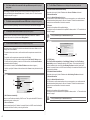
2.3 Using the machine in a multiple access point setup
Confirm the following the access point to be used can communicate with the machine and the
computer.
Windows XP may automatically connect to an unintended access point. Follow the steps below to
make your access point the highest priority.
a Select Start and Connect To.
b Right click Wireless Network Connection and select Properties.
c Click Wireless Networks tab and confirm that Use Windows to configure my wireless
network settings is checked.
d Confirm that the target access point is displayed in the Preferred networks list.
If the access point is not set to the top in the list, select and move the access point to the top
of the list using the Move up.
If multiple networks are available when using Macintosh, select System Preferences, select
Network, select AirPort and click Advanced (Mac OS X v.10.4.x/v.10.3.9: select Network Port
Configuration), then change the priority of the network name that you want to use. If the network
name is not set to the highest priority, select and move it to the top of the list (the highest priority).
3
How to set a network key/network password
3.2 How to set a WEP/WPA/WPA2 key (continued)
• When using WPA/WPA2
3.1 About Network Key (Windows)/Network Password (Macintosh)
An encryption key used in wireless networks. As using passwords, settings must match among
the access point, the machine, and the computer. A WEP key is used in the WEP authentication
method, while Passphrase or Pre-Shared Key is used in the WPA/WPA2 authentication method.
• Names of network keys vary depending on your access point or application software.
The authentication method, passphrase, and dynamic encryption type must match on the access
point, the machine, and the computer.
Enter the passphrase configured on the access point (a sequence of between 8 and 63
alphanumeric characters, or a 64-character hexadecimal number). If you do not know the
passphrase, refer to the manual provided with the access point, or contact its manufacturer.
Select either TKIP (Basic Encryption) or AES (Secure Encryption) for the dynamic encryption
method.
• This machine supports WPA-PSK (WPA-Personal) or WPA2-PSK (WPA2-Personal). WPA/
WPA2-Enterprise is not supported.
3.2 How to set a WEP/WPA/WPA2 key
• When using WEP
The key length, key format, the key to use (out of 1 to 4), and the authentication method must
match among the access point, the machine, and the computer.
4
Cannot connect to the machine (the machine is not detected)
For access points that use automatically generated WEP keys, use the hexadecimal key format
for the machine.
4.1 The machine is not detected
If you do not know the access point WEP key, refer to documentation provided with the access
point or contact its manufacturer.
• Refer to “1 Connection checklist” on page 1 and make sure there is no problem.
Example:
Using 64 bit key length, when the string “canon” is entered, an access point generates the
following codes.
- Key 1: C9 42 28 B8 AE
- Key 2: 87 C0 FB 05 6B
- Key 3: 9A 15 FB F6 F3
- Key 4: 62 56 67 58 44
In order to communicate with such an access point, you must configure the machine to use the
key generated by the access point by entering it in hexadecimal format.
Normally, select Auto for the Authentication. Otherwise, select Open System or Shared Key
according to the setting of the access point.
When entering a WEP key in Network Key or Network Password on the Access Points
screen, the key number is set to 1 and the Authentication is set to Auto. The key length and
format are based upon value of the entered key.
• When using AirPort, confirm the settings in Wireless Security of AirPort Admin Utility.
- Select 64 bit if 40 bit WEP is selected for the Key Length in the AirPort Base Station.
- Select 1 for Key ID. Otherwise the computer will not be able to communicate with the
machine via the access point.
• If the access point is configured to use access control, register the IP address or the MAC
address of the machine or disable the access control.
• Confirm the network name/SSID of the target access point and set the machine to use the
identical network name/SSID. If the network name/SSID is different in the machine and the
access point, the machine cannot connect to the access point. For details, refer to “5.1 The
Access Points screen is displayed during setup” on page 3.
• Make sure that the machine and the access point can communicate with each other under this
setting. When encryption is set to the access point, set up the encryption of the machine to
match the settings of the access point. If the WEP/WPA/WPA2 (encryption key) is different in
the machine and the access point, the machine cannot communicate with the access point. For
details, refer to “3.2 How to set a WEP/WPA/WPA2 key” on page 2.
• The wireless channel to be used may be limited depending on wireless network devices installed
in the computer. Confirm the wireless channels available for the network device. For details,
refer to the manual provided with your computer or your wireless network device.
Make sure that the channel set to the access point is valid to communicate with the computer,
confirmed above. If not, change the channel set to the access point.
4.2 No machine is detected after the network settings are changed in Windows
Wait until the IP address is assigned to the computer. You may need to restart your computer.
Search for the machine again after confirming a valid IP address is assigned to the computer.
5
5.1 The Access Points screen is displayed during setup (continued)
The following screen is displayed during setup
(C) Configuration
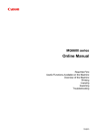
5.1 The Access Points screen is displayed during setup
The detailed settings dialog box is displayed. The network password (WEP) or the network key
(WPA/WPA2) selected in Encryption Method can be confirmed and changed.
The Access Points screen is displayed when:
(D) Connect
Connects to the specified access point.
- No access point is detected.
- Multiple access points are detected.
Select the target access point, then perform necessary operation such as setting of encryption.
If you want to specify access point manually, click Manual Setup in the Access Points screen.
Enter the settings for the target access point in the Manual Setup screen, then click Connect.
The target access point is searched with the specified settings.
(B)
(C)
For changing settings of the access point, refer to the manual provided with the access point or
contact its manufacturer.
• If you connect to a network that is not protected with security measures, there is a risk of
disclosing data such as your personal information to a third party.
(A)
(D)
(A) Network (SSID)
Enter the Network (SSID) set to the access point. The Network (SSID) is case sensitive. When
using AirPort, enter the Network (SSID) in alphanumeric characters.
SSID is also called ESS-ID. For details, refer to the manual provided with the access point or
contact its manufacturer.
(B)
(A)
(C)
(D)
(A) SSID
Enter the SSID set to the access point. The SSID is case sensitive. When using AirPort, enter the
network name (SSID) in alphanumeric characters.
SSID is also called ESS-ID. For details, refer to the manual provided with the access point or
contact its manufacturer.
(B) Encryption Method
• Do not use
Select to disable encryption.
• Use WEP
Transmission is encrypted using the WEP key you specified.
• Use WPA/Use WPA2
Transmission is encrypted using the passphrase (WPA/WPA2 key) you specified.
The actual encryption key is renewed automatically at a certain time interval, making the
transmission harder to break.
• If a WEP key/Passphrase (WPA/WPA2 key) has not been set, a detailed settings dialog box
is displayed. To change the settings, click the Configuration in the Manual Setup dialog
box. For details, refer to “3.1 About Network Key (Windows)/Network Password (Macintosh)”
on page 2.
(B) Encryption Method
• Do not use
Select to disable encryption
• Use Password (WEP)
Transmission is encrypted using the password (WEP key) you specified.
• Use WPA/Use WPA2
Transmission is encrypted using the passphrase (WPA/WPA2 key) you specified.
The actual encryption key is renewed automatically at a certain time interval, making the
transmission harder to break.
• If a password (WEP key)/passphrase (WPA/WPA2 key) has not been set, a detailed
settings screen is displayed. To change the settings, click the Configuration in the Manual
Setup dialog. For details, refer to “3.1 About Network Key (Windows)/Network Password
(Macintosh)” on page 2.
(C) Configuration
The detailed settings screen is displayed. The password (WEP key) or the passphrase (WPA/
WPA2 key) selected in Encryption Method can be confirmed and changed.
(D) Connect
Connects to the specified access point.
5.2 The An access point could not be detected is displayed during setup
This message is displayed when no access point is detected. Clicking the OK displays the Access
Points screen. For details, refer to “2.1 The target access point is not detected” on page 1.
5.3 The Printer could not be connected to the specified access point is displayed
during setup
This message is displayed when the machine could not connect to the target access point.
Clicking the OK displays the Access Points screen. For details, refer to “2.2 Cannot connect to
the target access point” on page 1.
5.4 The Another access point with the same SSID exists is displayed during setup
Cancel the current setup and change the SSID of the access point, then start the setup again.
5.5 The New port could not be created is displayed during setup
Uninstall the drivers, then setup the machine again following the procedures in “Install the
Software” and onward in the printed manual: Getting Started.
5.6 The Set Printer IP Address screen is displayed during setup (continued)
(C) IP Address/Subnet Mask/Default Gateway
Enter each value to specify a fixed IP address when Use next IP Address is selected.
(D) Network Information
Displays the Network Information dialog box.
Click this button to confirm network settings when your access point or your machine cannot be
detected automatically during setup for use over the network. This button is enabled when an
access point was not detected or could not be connected.
(E) Connect
Searches for the machine with the specified settings.
If the machine is still not be detected with a specified IP address, refer to “4.1 The machine is not
detected” on page 2.
• Clicking the Back displays the Access Points dialog box.
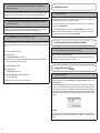
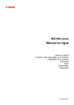
5.6 The Set Printer IP Address screen is displayed during setup
(A)
The following screen is displayed if no machine was detected on the network. Make sure of the
following, and click the Connect.
(B)
• The network devices are turned on, and the machine and the computer are connected to the
network.
(C)
(D)
• The machine and the computer are connected with the USB cable.
• The IP address to be set for the machine is displayed on the Set Printer IP Address screen.
If it is different from the address you want to set for the machine, select Use next IP address
and enter the desired IP address.
(If the machine is turned off, the Set Printer IP Address screen does not appear.)
If it still fails, specify the IP address of the machine and click Connect to retry the detection of the
machine.
(A) TCP/IP Setting
Select Get IP address automatically or Use following IP address. Select Get IP address
automatically to use an IP address provided by a DHCP server. This requires that the DHCP
function is enabled on the router. Select Use following IP address to manually specify an IP
address, for example if there is no DHCP server functionality in the network environment in which
you are using the machine.
(B) IP Address/Subnet Mask/Router
Enter each value to specify a fixed IP address when Use following IP address is selected.
(C) Network Information
(A)
(B)
(C)
(D)
(E)
(A) Get IP address automatically
Select to use an IP address provided by a DHCP server. This requires that the DHCP function is
enabled on the router or access point.
(B) Use next IP address
Select to manually specify an IP address, for example if there is no DHCP server functionality in
the network environment in which you are using the machine.
Displays the Network Information window.
Click this button to confirm network settings when your access point or your machine cannot be
detected automatically during setup for use over the network. This button is enabled when an
access point was not detected or could not be connected.
(D) Connect
Searches for the machine with the specified settings.
If the machine is still not be detected with a specified IP address, refer to “4.1 The machine is not
detected” on page 2.
• Clicking the Back displays the Access Points dialog.
5.7 The Enter Password screen is displayed during setup
The Enter Password screen is displayed if an administrator password is set to the machine which
has already been set up.
Admin Password
Enter the administrator password you have set. The administrator password consists of
alphanumeric characters and is no longer than 32 characters. The password is case sensitive.
For security, your entry will be displayed by “*” (asterisks) for Windows and “●” (bullets) for
Macintosh.
5.9 The Communication with the Card Slot failed is displayed during setup (continued)
To open port 137:139:
a Open the screen for setting Windows Firewall.
• Windows Vista
Click Start > Control Panel > Allow a program through Windows Firewall. User
Account Control dialog box appears, click Continue.
• Windows XP/2000
Click Start > Control Panel > Security Center > Windows Firewall.
b Select the Exceptions tab, and click Add port.
5.8 The You have connected the printer to an unsecured wireless network is
displayed during setup
Security is not configured on the access point.
The machine can still be used, so continue the setup procedure to complete it.
• If you connect to a network that is not protected with security measures, there is a risk of
disclosing data such as your personal information to a third party.
c On the Add a Port dialog box, input the following information, and click OK.
- Name: Input any name for the port.
- Port number: Input “137”.
- TCP/UDP: Select TCP.
d Repeat steps b and c.
On the Add a Port dialog box, input the same information as you did in step c except for
selecting UDP in TCP/UDP.
e Use the same procedure to open the other ports (138TCP, 138UDP, 139TCP, and 139UDP).
f Confirm that the port names are added on the Exceptions sheet, and click OK.
5.9 The Communication with the Card Slot failed is displayed during setup
• Change the workgroup name to “WORKGROUP” following the procedure below.
(A) Retry
a Open the System Properties screen.
• Windows Vista
Click Start, right-click Computer, select Properties, then click Change settings in the
Computer name, domain, and workgroup settings column. User Account Control
dialog box appears, click Continue.
• Windows XP/2000
Right-click My Computer, then select Properties.
Click to retry the network setup of the Card Slot.
b Select the Computer Name tab, then click Change.
This message is displayed when installation of the network drive of the Card Slot fails during
setup.
Wait for a while, then click Retry.
(B) Skip
Click to continue installation without the network setup of the Card Slot.
If it fails again after clicking Retry, follow the procedure below.
• Make sure that the computer is communicating with the network properly, then try again.
• Disable the Windows Firewall function, or open port 137:139 to allow communication with the
machine following the procedure below. For information on other security software, refer to its
instruction manual or contact its manufacturer.
• If you disabled the firewall function, disconnect your network from the Internet. To do this,
configure your router not to connect to the Internet or WAN.
To disable the Windows Firewall:
a Open the screen for setting Windows Firewall.
• Windows Vista
Click Start > Control Panel > Allow a program through Windows Firewall. User
Account Control dialog box appears, click Continue.
• Windows XP/2000
Click Start > Control Panel > Security Center > Windows Firewall.
c Change the workgroup name to “WORKGROUP”, then click OK.
• If the problem is not resolved, click Skip to complete the installation without the network
setup of the Card Slot. After installation is complete, to mount the Card Slot using
the Canon IJ Network Tool, refer to “Using the Card Slot over a Network” in “About
Network Communication” in “Appendix” of the on-screen manual: Advanced Guide. To
mount the Card Slot manually, refer to “Cannot Mount the Card Slot” in “About Network
Communication” in “Troubleshooting” of the on-screen manual: Advanced Guide.
• Make sure that a memory card is inserted in the Card Slot. If it is not inserted, insert it.
• Depending on the Mac OS version, the authentication screen may appear. If it appears, click
OK.
• If the problem is not resolved, click Skip to complete the setup without the network setup
of the Card Slot. To mount the Card Slot manually, refer to “Cannot Mount the Card Slot” in
“About Network Communication” in “Troubleshooting” of the on-screen manual: Advanced
Guide.
b Select the General tab, check Off, then click OK.
5.10 The The Card Slot is already mapped as Network Drive to this computer is
displayed during setup
The Card Slot has already been mapped as the network drive. The Card Slot is already available.
Click OK to close the screen, then click Next on the Network Setup of the Card Slot screen.
5.11 The Cannot map any more drives, because all the drive letters are assigned is
displayed during setup
Click Skip to complete the setup. After software installation is complete, remove any drive letter
and try the network setup of the Card Slot again using the Canon IJ Network Tool.
6
Re-setting the machine
6.1 Re-setting the machine
• Restore the machine to the factory default and set up the machine again. For details, refer to
“Restoring the Machine to the Factory Settings” on page 7.
To set up the machine again, follow the procedures in “Install the Software” and onward in the
printed manual: Getting Started.
• If you have changed the connection method via Change WLAN/LAN in the machine’s LAN
setting, you need to setup the machine again. To do so, follow the procedures in “Install the
Software” and onward in the printed manual: Getting Started.
5.12 The Timeout error screen is displayed during WPS setup
This screen is displayed when WPS setup is not completed within the specified time (2 minutes for
the push button method, and 10 minutes for the PIN code method). Retry following the procedures
below.
• When using the push button method
a Press the OK button.
The Push button method screen returns.
b When the access point is ready, press the OK button on the machine, then press the WPS
button on the access point within two minutes.
• When using the PIN code method
a Press the OK button.
The WPS setting screen returns.
7
The admin password set to the machine was forgotten
7.1 The admin password set to the machine was forgotten
Restore the machine setting to factory default.
All settings previously set will be lost after initialization. Set up the machine again to use it. For
details, refer to “6.1 Re-setting the machine” on page 6.
8
Changing the port name
b Select PIN code method and press the OK button.
A new PIN code appears.
8.1 Changing the port name
c Set the new PIN code to the access point or computer.
To change the port name, click View Setup Results in the Setup Completion dialog box, then
click Set Port Name.
The Set Port Name dialog box is displayed, where you specify the port name. By changing the
port name, you can change the name of the machine. When you set up an additional computer to
use the machine whose port name you changed, the machine is displayed with the changed port
name. When two or more computers are set up, the changed name is displayed. When multiple
computers or machines are present, this can be used to change the name to one that is easy to
remember.
Port Name
Port names should consist of alphanumeric characters and be no longer than 21 characters,
excluding the prefix. The port name includes the fixed prefix “CNBJNP_”, which you do not need
to enter.
Restoring the Machine to the Factory Settings
1
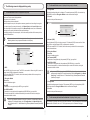
e Make sure that Yes is selected and press the OK button.
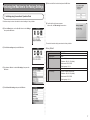
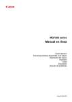
Initializing using the machine’s Operation Panel
Follow these steps to restore the machine’s network settings to factory defaults.
f Confirm that the right screen appears.
After a while, the LAN settings screen returns.
a Press the Menu button, use the [ or ] button to select Settings,
then press the OK button.
The machine’s network settings are restored to factory defaults.
b Select Device settings and press the OK button.
Factory Default
Wireless LAN
SSID
Data encryption
TCP/IP settings
Active
BJNPSETUP
Disable
Obtain an IP address automatically
• IP address: 192.168.1.123 (default)
• Subnet mask: 255.255.255.0
c Use the { or } button to select LAN settings, then press the
OK button.
Wired LAN
TCP/IP settings
• Default gateway: 0.0.0.0
Inactive
Obtain an IP address automatically
• IP address: 192.168.2.123 (default)
• Subnet mask: 255.255.255.0
• Default gateway: 0.0.0.0
d Select Reset LAN settings and press the OK button.
Specifications
1
MX860 series
Copy Specifications
General Specifications
Printing resolution 9600 (horizontal)* x 2400 (vertical)
(dpi)
*Ink droplets can be placed with a pitch of 1/9600 inch at minimum.
Interface
USB Port:
Hi-Speed USB *1
Direct Print Port:
PictBridge
Bluetooth v2.0 (Option) *2 *3 *4
USB flash drive
LAN Port:
Wired LAN: 100BASE-TX/10BASE-T
Wireless LAN: IEEE802.11b/IEEE802.11g *5
Print width
Acoustic noise
level
Operating
environment
Storage
environment
Power supply
Power
consumption
Eternal
dimensions
Weight
Print Head/Ink
ADF capacity
*1A computer that complies with Hi-Speed USB standard is required. Since the Hi-Speed USB interface
is fully upwardly compatible with USB 1.1, it can be used at USB 1.1.
*2Maximum speed: 1.44 Mbps
*3JPEG/PNG only
*4Bluetooth connection is for printing only.
*5Setup possible through WPS (Wi-Fi Protected Setup) and WCN (Windows Connect Now).
8 inches /203.2 mm
(for Borderless Printing: 8.5 inches/216 mm)
Approx. 43.5 db(A)
*When printing in the standard print quality mode on Photo Paper Plus Glossy II.
Temperature: 5 to 35°C (41 to 95°F)
Humidity: 10 to 90% RH (no condensation)
Temperature: 0 to 40°C (32 to 104°F)
Humidity: 5 to 95% RH (no condensation)
AC 100-240V, 50/60 Hz
Printing (Copy): Approx. 21 W
Standby (minimum): Approx. 4.1 W *
OFF: Approx. 1.6 W *
*USB connection to PC
Approx. 19.4 (W) x 17.1 (D) x 8.9 (H) inches
Approx. 491 (W) x 437 (D) x 226 (H) mm
*With the Paper Support and Paper Output Tray retracted.
Approx. 11.8 kg (Approx. 26.1 lb)
*With the Print Head and ink tanks installed.
Total 2,368 nozzles (PgBK 320 nozzles, Y/DyeBK each 256 nozzles, C/M each 768 nozzles)
A4 or Letter size: Max. 35 sheets (20 lb / 75 gsm paper), up to 0.20 inches / 5 mm in height
Legal size: Max. 30 sheets (20 lb / 75 gsm paper), up to 0.16 inches / 4 mm in height
Other sizes: 1 sheet
Multiple copy
Intensity
adjustment
Reduction/
Enlargement
Max 99 pages
9 positions, Auto intensity (AE copy)
25%-400% (1% unit)
Scan Specifications
Scanner driver
Maximum
scanning size
Scanning
resolution
TWAIN/WIA (Windows Vista and Windows XP only)
Platen Glass: A4/Letter/8.5'' x 11.7' (216 x 297 mm)
ADF: A4/Letter/8.5'' x 14.0' (216 x 356 mm)
Optical resolution (horizontal vertical) max:
2400 dpi x 4800 dpi
Interpolated resolution max: 19200 dpi x 19200 dpi
Gradation (Input/ Gray: 16 bit/8 bit
Output)
Color: 48 bit/24 bit (RGB each 16 bit/8 bit)
Network Specifications
Communication
protocol
Wireless LAN
TCP/IP
Supported Standards:
Transfer speed:
IEEE802.11b:
IEEE802.11g:
Frequency bandwidth *1:
IEEE802.11b/IEEE802.11g
11/5.5/2/1 Mbps
54/48/36/24/18/12/9/6 Mbps
2.412 GHz-2.462 GHz or
2.412 GHz-2.472 GHz
Channel *1:
1-11 or 1-13
Communication distance: Indoors 50 m *2
Security:
Encryption by WPA-PSK, WPA2-PSK, or WEP (64/128 bits), and access
control by passwords
Wired LAN
*1Frequency bandwidth and available channels differ depending on country or region.
*2Effective range varies depending on the installation environment and location.
Supported Standards:IEEE802.3u (100BASE-TX)/IEEE802.3 (10BASE-T)
10M/100Mbps (auto switching)
Transfer speed:
Minimum System Requirements
Fax Specifications
Applicable line
Compatibility
Data compressing
system
Modem type
Modem speed
Transmission
speed
Scanning image
processing
Memory
Fax resolution
Dialing
Telephone
networking
Public Switched Telephone Network (PSTN)
G3 / Super G3 (Mono & Color Fax)
MH, MR, MMR, JPEG
Fax modem
33600 / 31200 / 28800 / 26400 / 24000 / 21600 / 19200 / 16800 / 14400 / 12000 / 9600 / 7200 / 4800 /
2400 bps
Automatic fallback
Black & white: Approx. 3 seconds/page at 33.6 Kbps, ECM-MMR, transmitting from memory
(Based on ITU-T No.1 chart for US specifications and Canon FAX Standard chart No.1 for others, both in
standard mode or Canon FAX Standard chart No.1, standard mode.)
Color: Approx. 1 minute/page at 33.6 Kbps, ECM-JPEG, transmitting from memory
(Based on Canon COLOR FAX TEST SHEET.)
Halftones: 256 levels of gray
Density adjustment: 3 levels
Transmission/reception: 250 pages
(Based on ITU-T No.1 chart for US specifications and Canon FAX Standard chart No.1 for others, both in
standard mode.)
Black & white Standard: 8 pels / mm x 3.85 lines / mm (203 pels / inch x 98 lines / inch)
Black & white Fine, Photo: 8 pels / mm x 7.70 lines / mm (203 pels / inch x 196 lines / inch)
Black & white Extra fine: 300 x 300 dpi
Color: 200 x 200 dpi
Automatic dialing
One-touch speed dial (5 destinations)
Coded speed dial (100 destinations)
Group dial (max. 104 destinations)
Regular dialing (with Numeric buttons)
Automatic redialing
Manual redialing (with the Redial/Pause button)
TTI (Transmit Terminal Identification)
ECM transmission
Activity report (after every 20 transactions)
Sequential broadcasting (max. 106 destinations)
Manual redialing (max.10 transactions)
Automatic reception
Remote reception by telephone (Default ID: 25)
DM Preventive Function
etc.
Conform to the operating system’s requirements when higher than those given here.
Operating System Windows Vista, Vista SP1
Processor
1 GHz processor
RAM
512 MB
Browser
Hard Disk Space
Mac OS X v.10.5
Intel processor, PowerPC G5, PowerPC G4
(867 MHz or faster)
512 MB
Windows XP SP2, SP3
300 MHz processor
128 MB
Mac OS X v.10.4
Intel processor, PowerPC G5, PowerPC G4,
PowerPC G3
256 MB
Windows 2000 Professional SP4
300 MHz processor
128 MB
Internet Explorer 6.0 or later
600 MB
Note: For bundled software installation.
Mac OS X v.10.3.9
PowerPC G5, PowerPC G4, PowerPC G3
128 MB
Safari
700 MB
Note: For bundled software installation.
CD-ROM Drive
Required
Display
XGA 1024 x 768
• Windows: Note: Operation can only be guaranteed on a PC with Windows Vista, XP or 2000 pre-installed.
• Some functions may not be available with Windows Media Center.
• To upgrade from Windows XP to Windows Vista, first uninstall software bundled with the Canon inkjet printer.
• Macintosh: Hard Disk must be formatted as Mac OS Extended (Journaled) or Mac OS Extended.
Additional System Requirements for the on-screen manuals
Browser: Easy Guide Viewer
Browser: Help Viewer
Note: Microsoft Internet Explorer 6.0 or later must be
Note: The on-screen manual may not be displayed properly
installed. The on-screen manual may not be displayed
depending on your operating system. We recommend
that you keep your system up to date.
properly depending on your operating system or
Internet Explorer version. We recommend that you
keep your system up to date with Windows Update.
Specifications are subject to change without notice.
About Consumables
Consumables (ink tanks / FINE Cartridges) are available for 5 years after production has
stopped.
QT5-2117-V01
XXXXXXXX
©CANON INC.2009
PRINTED IN THAILAND