1
Quick-Starting Routers
BayRS Version 12.10
Site Manager Software Version 6.10
BCC Version 3.20
Part No. 117342-B Rev. 00
February 1998
4401 Great America Parkway
Santa Clara, CA 95054
8 Federal Street
Billerica, MA 01821
Copyright © 1998 Bay Networks, Inc.
All rights reserved. Printed in the USA. February 1998.
The information in this document is subject to change without notice. The statements, configurations, technical data,
and recommendations in this document are believed to be accurate and reliable, but are presented without express or
implied warranty. Users must take full responsibility for their applications of any products specified in this document.
The information in this document is proprietary to Bay Networks, Inc.
The software described in this document is furnished under a license agreement and may only be used in accordance
with the terms of that license. A summary of the Software License is included in this document.
Trademarks
AN, BCN, BLN, BN, BNX, FRE, GAME, Nautica, Optivity, PPX, Quick2Config, and Bay Networks are registered
trademarks and Advanced Remote Node, ANH, ARN, ASN, BayRS, BaySecure, BayStack, BCC, SPEX,
System 5000, and the Bay Networks logo are trademarks of Bay Networks, Inc.
Microsoft, MS, MS-DOS, Windows, and Windows NT are registered trademarks of Microsoft Corporation.
All other trademarks and registered trademarks are the property of their respective owners.
Restricted Rights Legend
Use, duplication, or disclosure by the United States Government is subject to restrictions as set forth in subparagraph
(c)(1)(ii) of the Rights in Technical Data and Computer Software clause at DFARS 252.227-7013.
Notwithstanding any other license agreement that may pertain to, or accompany the delivery of, this computer
software, the rights of the United States Government regarding its use, reproduction, and disclosure are as set forth in
the Commercial Computer Software-Restricted Rights clause at FAR 52.227-19.
Statement of Conditions
In the interest of improving internal design, operational function, and/or reliability, Bay Networks, Inc. reserves the
right to make changes to the products described in this document without notice.
Bay Networks, Inc. does not assume any liability that may occur due to the use or application of the product(s) or
circuit layout(s) described herein.
Portions of the code in this software product may be Copyright © 1988, Regents of the University of California. All
rights reserved. Redistribution and use in source and binary forms of such portions are permitted, provided that the
above copyright notice and this paragraph are duplicated in all such forms and that any documentation, advertising
materials, and other materials related to such distribution and use acknowledge that such portions of the software were
developed by the University of California, Berkeley. The name of the University may not be used to endorse or
promote products derived from such portions of the software without specific prior written permission.
SUCH PORTIONS OF THE SOFTWARE ARE PROVIDED “AS IS” AND WITHOUT ANY EXPRESS OR
IMPLIED WARRANTIES, INCLUDING, WITHOUT LIMITATION, THE IMPLIED WARRANTIES OF
MERCHANTABILITY AND FITNESS FOR A PARTICULAR PURPOSE.
In addition, the program and information contained herein are licensed only pursuant to a license agreement that
contains restrictions on use and disclosure (that may incorporate by reference certain limitations and notices imposed
by third parties).
ii
117342-B Rev. 00
Bay Networks, Inc. Software License Agreement
NOTICE: Please carefully read this license agreement before copying or using the accompanying software or
installing the hardware unit with pre-enabled software (each of which is referred to as “Software” in this Agreement).
BY COPYING OR USING THE SOFTWARE, YOU ACCEPT ALL OF THE TERMS AND CONDITIONS OF
THIS LICENSE AGREEMENT. THE TERMS EXPRESSED IN THIS AGREEMENT ARE THE ONLY TERMS
UNDER WHICH BAY NETWORKS WILL PERMIT YOU TO USE THE SOFTWARE. If you do not accept these
terms and conditions, return the product, unused and in the original shipping container, within 30 days of purchase to
obtain a credit for the full purchase price.
1. License Grant. Bay Networks, Inc. (“Bay Networks”) grants the end user of the Software (“Licensee”) a personal,
nonexclusive, nontransferable license: a) to use the Software either on a single computer or, if applicable, on a single
authorized device identified by host ID, for which it was originally acquired; b) to copy the Software solely for backup
purposes in support of authorized use of the Software; and c) to use and copy the associated user manual solely in
support of authorized use of the Software by Licensee. This license applies to the Software only and does not extend
to Bay Networks Agent software or other Bay Networks software products. Bay Networks Agent software or other
Bay Networks software products are licensed for use under the terms of the applicable Bay Networks, Inc. Software
License Agreement that accompanies such software and upon payment by the end user of the applicable license fees
for such software.
2. Restrictions on use; reservation of rights. The Software and user manuals are protected under copyright laws.
Bay Networks and/or its licensors retain all title and ownership in both the Software and user manuals, including any
revisions made by Bay Networks or its licensors. The copyright notice must be reproduced and included with any
copy of any portion of the Software or user manuals. Licensee may not modify, translate, decompile, disassemble, use
for any competitive analysis, reverse engineer, distribute, or create derivative works from the Software or user manuals
or any copy, in whole or in part. Except as expressly provided in this Agreement, Licensee may not copy or transfer
the Software or user manuals, in whole or in part. The Software and user manuals embody Bay Networks’ and its
licensors’ confidential and proprietary intellectual property. Licensee shall not sublicense, assign, or otherwise
disclose to any third party the Software, or any information about the operation, design, performance, or
implementation of the Software and user manuals that is confidential to Bay Networks and its licensors; however,
Licensee may grant permission to its consultants, subcontractors, and agents to use the Software at Licensee’s facility,
provided they have agreed to use the Software only in accordance with the terms of this license.
3. Limited warranty. Bay Networks warrants each item of Software, as delivered by Bay Networks and properly
installed and operated on Bay Networks hardware or other equipment it is originally licensed for, to function
substantially as described in its accompanying user manual during its warranty period, which begins on the date
Software is first shipped to Licensee. If any item of Software fails to so function during its warranty period, as the sole
remedy Bay Networks will at its discretion provide a suitable fix, patch, or workaround for the problem that may be
included in a future Software release. Bay Networks further warrants to Licensee that the media on which the
Software is provided will be free from defects in materials and workmanship under normal use for a period of 90 days
from the date Software is first shipped to Licensee. Bay Networks will replace defective media at no charge if it is
returned to Bay Networks during the warranty period along with proof of the date of shipment. This warranty does not
apply if the media has been damaged as a result of accident, misuse, or abuse. The Licensee assumes all responsibility
for selection of the Software to achieve Licensee’s intended results and for the installation, use, and results obtained
from the Software. Bay Networks does not warrant a) that the functions contained in the software will meet the
Licensee’s requirements, b) that the Software will operate in the hardware or software combinations that the Licensee
may select, c) that the operation of the Software will be uninterrupted or error free, or d) that all defects in the
operation of the Software will be corrected. Bay Networks is not obligated to remedy any Software defect that cannot
be reproduced with the latest Software release. These warranties do not apply to the Software if it has been (i) altered,
except by Bay Networks or in accordance with its instructions; (ii) used in conjunction with another vendor’s product,
resulting in the defect; or (iii) damaged by improper environment, abuse, misuse, accident, or negligence. THE
FOREGOING WARRANTIES AND LIMITATIONS ARE EXCLUSIVE REMEDIES AND ARE IN LIEU OF ALL
OTHER WARRANTIES EXPRESS OR IMPLIED, INCLUDING WITHOUT LIMITATION ANY WARRANTY OF
MERCHANTABILITY OR FITNESS FOR A PARTICULAR PURPOSE. Licensee is responsible for the security of
117342-B Rev. 00
iii
its own data and information and for maintaining adequate procedures apart from the Software to reconstruct lost or
altered files, data, or programs.
4. Limitation of liability. IN NO EVENT WILL BAY NETWORKS OR ITS LICENSORS BE LIABLE FOR ANY
COST OF SUBSTITUTE PROCUREMENT; SPECIAL, INDIRECT, INCIDENTAL, OR CONSEQUENTIAL
DAMAGES; OR ANY DAMAGES RESULTING FROM INACCURATE OR LOST DATA OR LOSS OF USE OR
PROFITS ARISING OUT OF OR IN CONNECTION WITH THE PERFORMANCE OF THE SOFTWARE, EVEN
IF BAY NETWORKS HAS BEEN ADVISED OF THE POSSIBILITY OF SUCH DAMAGES. IN NO EVENT
SHALL THE LIABILITY OF BAY NETWORKS RELATING TO THE SOFTWARE OR THIS AGREEMENT
EXCEED THE PRICE PAID TO BAY NETWORKS FOR THE SOFTWARE LICENSE.
5. Government Licensees. This provision applies to all Software and documentation acquired directly or indirectly by
or on behalf of the United States Government. The Software and documentation are commercial products, licensed on
the open market at market prices, and were developed entirely at private expense and without the use of any U.S.
Government funds. The license to the U.S. Government is granted only with restricted rights, and use, duplication, or
disclosure by the U.S. Government is subject to the restrictions set forth in subparagraph (c)(1) of the Commercial
Computer Software––Restricted Rights clause of FAR 52.227-19 and the limitations set out in this license for civilian
agencies, and subparagraph (c)(1)(ii) of the Rights in Technical Data and Computer Software clause of DFARS
252.227-7013, for agencies of the Department of Defense or their successors, whichever is applicable.
6. Use of Software in the European Community. This provision applies to all Software acquired for use within the
European Community. If Licensee uses the Software within a country in the European Community, the Software
Directive enacted by the Council of European Communities Directive dated 14 May, 1991, will apply to the
examination of the Software to facilitate interoperability. Licensee agrees to notify Bay Networks of any such
intended examination of the Software and may procure support and assistance from Bay Networks.
7. Term and termination. This license is effective until terminated; however, all of the restrictions with respect to
Bay Networks’ copyright in the Software and user manuals will cease being effective at the date of expiration of the
Bay Networks copyright; those restrictions relating to use and disclosure of Bay Networks’ confidential information
shall continue in effect. Licensee may terminate this license at any time. The license will automatically terminate if
Licensee fails to comply with any of the terms and conditions of the license. Upon termination for any reason,
Licensee will immediately destroy or return to Bay Networks the Software, user manuals, and all copies. Bay
Networks is not liable to Licensee for damages in any form solely by reason of the termination of this license.
8. Export and Re-export. Licensee agrees not to export, directly or indirectly, the Software or related technical data
or information without first obtaining any required export licenses or other governmental approvals. Without limiting
the foregoing, Licensee, on behalf of itself and its subsidiaries and affiliates, agrees that it will not, without first
obtaining all export licenses and approvals required by the U.S. Government: (i) export, re-export, transfer, or divert
any such Software or technical data, or any direct product thereof, to any country to which such exports or re-exports
are restricted or embargoed under United States export control laws and regulations, or to any national or resident of
such restricted or embargoed countries; or (ii) provide the Software or related technical data or information to any
military end user or for any military end use, including the design, development, or production of any chemical,
nuclear, or biological weapons.
9. General. If any provision of this Agreement is held to be invalid or unenforceable by a court of competent
jurisdiction, the remainder of the provisions of this Agreement shall remain in full force and effect. This Agreement
will be governed by the laws of the state of California.
Should you have any questions concerning this Agreement, contact Bay Networks, Inc., 4401 Great America Parkway,
P.O. Box 58185, Santa Clara, California 95054-8185.
LICENSEE ACKNOWLEDGES THAT LICENSEE HAS READ THIS AGREEMENT, UNDERSTANDS IT, AND
AGREES TO BE BOUND BY ITS TERMS AND CONDITIONS. LICENSEE FURTHER AGREES THAT THIS
AGREEMENT IS THE ENTIRE AND EXCLUSIVE AGREEMENT BETWEEN BAY NETWORKS AND
LICENSEE, WHICH SUPERSEDES ALL PRIOR ORAL AND WRITTEN AGREEMENTS AND
COMMUNICATIONS BETWEEN THE PARTIES PERTAINING TO THE SUBJECT MATTER OF THIS
AGREEMENT. NO DIFFERENT OR ADDITIONAL TERMS WILL BE ENFORCEABLE AGAINST BAY
NETWORKS UNLESS BAY NETWORKS GIVES ITS EXPRESS WRITTEN CONSENT, INCLUDING AN
EXPRESS WAIVER OF THE TERMS OF THIS AGREEMENT.
iv
117342-B Rev. 00
Contents
About This Guide
Before You Begin ...........................................................................................................................xiv
ASN Terminology ...........................................................................................................................xv
Conventions ....................................................................................................................................xv
Acronyms .......................................................................................................................................xvi
Bay Networks Technical Publications ..........................................................................................xvii
Bay Networks Customer Service ..................................................................................................xvii
How to Get Help ......................................................................................................................... xviii
Bay Networks Educational Services ........................................................................................... xviii
Chapter 1
Overview of Quick-Start
Chapter 2
Preparing the Router for Quick-Start
Connecting a PC or Terminal Console .......................................................................................... 2-2
Connecting a PC .................................................................................................................... 2-2
Connecting a Terminal Console ............................................................................................. 2-3
Connecting to the IP Network ....................................................................................................... 2-4
Logging On to the Technician Interface ........................................................................................ 2-5
Using Technician Interface Commands ........................................................................................ 2-6
Reviewing the Installation Files .................................................................................................... 2-8
Booting with the ti.cfg File ......................................................................................................... 2-10
Chapter 3
Preparing Your Network Information
Using the Quick-Start Worksheet .................................................................................................. 3-2
Using the Quick-Start ATM Worksheet ........................................................................................ 3-7
Using the Quick-Start Worksheet for WAN Protocols ................................................................ 3-12
117342-B Rev. 00
v
Chapter 4
Using the Installation Script to Quick-Start a Router
Quick-Start Troubleshooting ......................................................................................................... 4-4
Chapter 5
Using the BCC to Quick-Start a Router
Overview of the BCC .................................................................................................................... 5-2
Essential BCC Commands ............................................................................................................ 5-4
Quick-Starting Your Router with the BCC ................................................................................... 5-5
Quick-Start Troubleshooting with the BCC ................................................................................ 5-13
Chapter 6
Completing the Router Configuration
Selecting a Configuration Tool ..................................................................................................... 6-1
Completing the Configuration Procedure ..................................................................................... 6-2
Communicating with the Router Remotely .................................................................................. 6-3
Telnet Connections ................................................................................................................. 6-3
Out-Of-Band Connections ..................................................................................................... 6-4
Router Memory Card Distribution ......................................................................................... 6-4
Chapter 7
Securing the Router
Assigning a Password to the Technician Interface ........................................................................ 7-2
Securing New Routers with the BCC or the Installation Script .................................................... 7-3
Setting Global IP Access Policies with the BCC .......................................................................... 7-3
Restricting Read/Write Access with SNMP Communities ........................................................... 7-3
Setting Secure Mode ..................................................................................................................... 7-4
Specifying Secure Mode ........................................................................................................ 7-5
Authentication Failure Traps ......................................................................................................... 7-6
Assigning SecurID to Telnet Connections .................................................................................... 7-6
Turning Off FTP and Telnet on the Router ................................................................................... 7-6
Using the Image Builder to Remove Services .............................................................................. 7-6
Restricting Access to the HTTP Server ........................................................................................ 7-7
Configuring Data Encryption Services ......................................................................................... 7-7
Configuring RADIUS ................................................................................................................... 7-8
Installing BaySecure FireWall-1 ................................................................................................... 7-8
vi
117342-B Rev. 00
Chapter 8
Installing Site Manager on a PC
System Requirements .................................................................................................................... 8-1
Updating TCP/IP, Network Adapters, and Drivers ....................................................................... 8-2
Preparing the Network Control Panel .................................................................................... 8-3
Testing TCP/IP ....................................................................................................................... 8-3
Loading and Starting Site Manager Software ............................................................................... 8-4
Chapter 9
Installing Site Manager on a Workstation Running Windows NT
System Requirements .................................................................................................................... 9-1
Preparing the Network Control Panel ........................................................................................... 9-2
Testing TCP/IP .............................................................................................................................. 9-2
Loading and Starting Site Manager Software ............................................................................... 9-3
Chapter 10
Installing Site Manager on a SPARCstation
System Requirements .................................................................................................................. 10-2
Setting Up the SPARCstation ...................................................................................................... 10-2
Loading Site Manager Software ................................................................................................. 10-3
Mounting a CD-ROM Drive on SunOS and Solaris ............................................................ 10-3
Installing the Software ......................................................................................................... 10-4
Unmounting the CD-ROM Drive ........................................................................................ 10-4
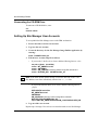
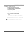
Setting Up Site Manager User Accounts .................................................................................... 10-5
Verifying Site Manager Installation ............................................................................................ 10-6
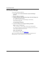
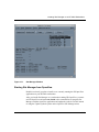
Starting Site Manager .................................................................................................................. 10-6
Starting Site Manager from SunNet Manager ..................................................................... 10-8
Starting Site Manager from OpenView ................................................................................ 10-9
Chapter 11
Installing Site Manager on an IBM Workstation
System Requirements ...................................................................................................................11-2
Loading Site Manager Software ..................................................................................................11-2
Mounting a CD-ROM Drive .................................................................................................11-3
Installing the Software ..........................................................................................................11-3
Unmounting the CD-ROM Drive .........................................................................................11-4
Setting Up Site Manager User Accounts .....................................................................................11-4
117342-B Rev. 00
vii
Verifying Site Manager Installation .............................................................................................11-5
Starting Site Manager ...................................................................................................................11-6
Starting Site Manager from NetView for AIX ......................................................................11-7
Chapter 12
Installing Site Manager on an HP 9000 Workstation
System Requirements .................................................................................................................. 12-2
Loading Site Manager Software ................................................................................................. 12-2
Mounting a CD-ROM Drive ................................................................................................ 12-3
Installing the Software ......................................................................................................... 12-3
Unmounting the CD-ROM Drive ........................................................................................ 12-4
Setting Up Site Manager User Accounts .................................................................................... 12-4
Verifying Site Manager Installation ............................................................................................ 12-5
Starting Site Manager .................................................................................................................. 12-6
Starting Site Manager from OpenView ................................................................................ 12-7
Appendix A
Sample Installation Script
Appendix B
Sample ATM Installation Script
Index
viii
117342-B Rev. 00
Figures
Figure 3-1.
Network Example for the Quick-Start Worksheet ............................................... 3-3
Figure 3-2.
Network Example for the Quick-Start ATM Worksheet ...................................... 3-8
Figure 5-1.
Configuring IP and RIP on an Ethernet Interface ................................................ 5-3
Figure 8-1.
Site Manager Window ......................................................................................... 8-5
Figure 9-1.
Site Manager Window ......................................................................................... 9-5
Figure 10-1.
Site Manager Window ....................................................................................... 10-7
Figure 10-2.
Starting a Site Manager Session from SunNet Manager ................................... 10-8
Figure 10-3.
Starting a Site Manager Session from OpenView ........................................... 10-10
Figure 11-1.
Site Manager Window ........................................................................................11-7
Figure 11-2.
Starting a Site Manager Session from NetView .................................................11-8
Figure 12-1.
Site Manager Window ....................................................................................... 12-7
Figure 12-2.
Starting a Site Manager Session from OpenView ............................................. 12-8
117342-B Rev. 00
ix
Tables
Table 2-1.
Initial Router Connectors to the IP Network ....................................................... 2-4
Table 2-2.
Basic Technician Interface Commands ................................................................ 2-7
Table 2-3.
Quick-Start Installation Files ............................................................................... 2-9
Table 2-4.
Router Software Images ................................................................................... 2-10
Table 3-1.
Quick-Start Worksheet ........................................................................................ 3-4
Table 3-2.
Quick-Start ATM Worksheet .............................................................................. 3-9
Table 3-3.
Quick-Start Worksheet for WAN Protocols ...................................................... 3-12
Table 4-1.
Installation Script Commands .............................................................................. 4-2
Table 5-1.
Essential BCC System and Navigation Commands ............................................ 5-4
117342-B Rev. 00
xi
About This Guide
If you are responsible for activating a Bay Networks® router on an IP network, this
guide can help you to configure the router’s initial network interface. When you
complete the Quick-Start installation procedure, the router will actively route IP
traffic on your network.
You can use the Quick-Start installation script or the BCC to configure the initial
IP interface over Ethernet on BN® and AN® routers. In this guide, you will find
instructions for using both the BCC and the Quick-Start installation script to
quick-start a router.
This guide also introduces you to router configuration and can help you to:
•
Connect to the router’s embedded tools:
--
The Technician Interface
--
The Bay Command Console (BCC™)
•
Choose a router configuration tool.
•
Secure your router.
•
Install the Site Manager configuration tool on a PC or workstation.
The procedures in this book are intended primarily for new installations, but they
are also used in the upgrade procedure. Before using this book as part of an
upgrade, see the upgrade section of the BayRS Version 12.10 Document Change
Notice.
117342-B Rev. 00
xiii
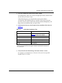
Quick-Starting Routers
.
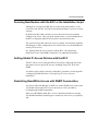
If you want to
Go to
Review a summary of the Quick-Start procedure.
Chapter 1
Prepare your router for the Quick-Start procedure by
connecting your router to a PC, terminal, or IP network and
establish a Technician Interface session.
Chapter 2
Prepare network information for the Quick-Start procedure.
Chapter 3
Use the installation script to quick-start a router.
Chapter 4
Use the BCC to quick-start a router.
Chapter 5
Complete the router configuration.
Chapter 6
Secure your router.
Chapter 7
Install Site Manager on a PC running Windows 95.
Chapter 8
Install Site Manager on a workstation running Windows NT.
Chapter 9
Install Site Manager on a SPARCstation.
Chapter 10
Install Site Manager on an IBM workstation.
Chapter 11
Install Site Manager on an HP 9000 workstation.
Chapter 12
View a sample installation script.
Appendix A
View a sample ATM installation script.
Appendix B
Before You Begin
Before using this guide, you must complete the following procedures:
•
•
xiv
Install the router (refer to the installation guide that came with your router):
--
Installing and Maintaining BN Routers
--
Installing and Maintaining ASN Routers
--
Installing and Operating BayStack AN and ANH Routers
--
Installing and Operating BayStack ARN Routers
--
Quick Installation and Reference for the System 5000 Net Modules
Review the Read Me First and Release Notes documents for any changes to
the Quick-Start instructions.
117342-B Rev. 00
About This Guide
Following are other considerations for using Quick-Start:
•
The Quick-Start procedure does not apply to the Nautica™ series of routers;
see Nautica documentation for all instructions.
•
For specific booting and installation script procedures for BayStack ™ AN®,
ANH™, and ARN™ routers, see Configuring BayStack Remote Access.
•
For ASN network booting information, see Connecting ASN Routers to a
Network.
•
For ASN local booting requirements, such as using the bconfig config local
and boot commands to allow the ASN to use its local configuration file, see
Installing and Maintaining ASN Routers.
ASN Terminology
ASN routers use unique terminology to identify the location of their connectors.
Four ASN nodes can be stacked together as a single router. You assign a slot
number to each node using a dial on its rear panel. Each slot has four module
positions where the net modules reside. You identify connector position by first
specifying the slot and module numbers. For more information, see Installing and
Maintaining ASN Routers.
Conventions
angle brackets (< >)
Indicate that you choose the text to enter based on the
description inside the brackets. Do not type the
brackets when entering the command.
Example: if command syntax is ping <ip_address>,
you enter ping 192.32.10.12
bold text
Indicates text that you need to enter, command names,
and buttons in menu paths.
Example: Enter wfsm &
Example: Use the dinfo command.
Example: ATM DXI > Interfaces > PVCs identifies the
PVCs button in the window that appears when you
select the Interfaces option from the ATM DXI menu.
117342-B Rev. 00
xv
Quick-Starting Routers
brackets ([ ])
Indicate optional elements. You can choose none, one,
or all of the options.
.
Horizontal (. . .) and vertical ( .. ) ellipsis points indicate
omitted information.
ellipsis points
italic text
Indicates variable values in command syntax
descriptions, new terms, file and directory names, and
book titles.
quotation marks (“ ”)
Indicate the title of a chapter or section within a book.
screen text
Indicates data that appears on the screen.
Example: Set Bay Networks Trap Monitor Filters
separator ( > )
Separates menu and option names in instructions and
internal pin-to-pin wire connections.
Example: Protocols > AppleTalk identifies the
AppleTalk option in the Protocols menu.
Example: Pin 7 > 19 > 20
Acronyms
xvi
BootP
Bootstrap Protocol
FDDI
Fiber Distributed Data Interface
FTP
File Transfer Protocol
HTTP
Hypertext Transfer Protocol
IP
Internet Protocol
ISO
International Organization for Standardization
ITU-T
International Telecommunication Union - Telecommunications
(formerly CCITT)
LAN
local area network
MAC
media access control
NIC
network interface card
NVFS
nonvolatile file system
OSPF
Open Shortest Path First (Protocol)
PPP
Point-to-Point Protocol
PVC
Permanent Virtual Circuit
QENET
Quad Ethernet link module
117342-B Rev. 00
About This Guide
RIP
Routing Information Protocol
SNMP
Simple Network Management Protocol
TCP/IP
Transmission Control Protocol/Internet Protocol
TFTP
Trivial File Transfer Protocol
WAN
wide area network
Bay Networks Technical Publications
You can now print technical manuals and release notes free, directly from the
Internet. Go to support.baynetworks.com/library/tpubs. Find the Bay Networks
products for which you need documentation. Then locate the specific category and
model or version for your hardware or software product. Using Adobe Acrobat
Reader, you can open the manuals and release notes, search for the sections you
need, and print them on most standard printers. You can download Acrobat Reader
free from the Adobe Systems Web site, www.adobe.com.
Documentation sets and CDs are available through your local Bay Networks sales
office or account representative.
Bay Networks Customer Service
You can purchase a support contract from your Bay Networks distributor or
authorized reseller, or directly from Bay Networks Services. For information
about, or to purchase a Bay Networks service contract, either call your local Bay
Networks field sales office or one of the following numbers:
Region
Telephone number
Fax number
United States and
Canada
800-2LANWAN; then enter Express Routing 978-916-3514
Code (ERC) 290, when prompted, to
purchase or renew a service contract
978-916-8880 (direct)
117342-B Rev. 00
Europe
33-4-92-96-69-66
33-4-92-96-69-96
Asia/Pacific
61-2-9927-8888
61-2-9927-8899
Latin America
561-988-7661
561-988-7550
xvii
Quick-Starting Routers
Information about customer service is also available on the World Wide Web at
support.baynetworks.com.
How to Get Help
If you purchased a service contract for your Bay Networks product from a
distributor or authorized reseller, contact the technical support staff for that
distributor or reseller for assistance.
If you purchased a Bay Networks service program, call one of the following Bay
Networks Technical Solutions Centers:
Technical Solutions Center
Telephone number
Fax number
Billerica, MA
800-2LANWAN
978-916-3514
Santa Clara, CA
800-2LANWAN
408-495-1188
Valbonne, France
33-4-92-96-69-68
33-4-92-96-69-98
Sydney, Australia
61-2-9927-8800
61-2-9927-8811
Tokyo, Japan
81-3-5402-0180
81-3-5402-0173
Bay Networks Educational Services
Through Bay Networks Educational Services, you can attend classes and purchase
CDs, videos, and computer-based training programs about Bay Networks
products. Training programs can take place at your site or at a Bay Networks
location. For more information about training programs, call one of the following
numbers:
Region
Telephone number
United States and Canada
800-2LANWAN; then enter Express Routing Code (ERC)
282 when prompted
978-916-3460 (direct)
xviii
Europe, Middle East, and
Africa
33-4-92-96-15-83
Asia/Pacific
61-2-9927-8822
Tokyo and Japan
81-3-5402-7041
117342-B Rev. 00
Chapter 1
Overview of Quick-Start
The Quick-Start procedure boots your router locally and configures its initial
interface to an IP network. To complete the Quick-Start procedure, follow these
steps:
1.
Connect a PC or ASCII console to the router.
Connect a PC or a terminal to the router’s console port to access the
Technician Interface (Chapter 2).
2.
Connect the router to the IP network.
Connect a cable between the router and the IP network (Chapter 2).
3.
Establish a Technician Interface session.
Use the Technician Interface to run the installation script or to start the BCC
(Chapter 2).
4.
Boot the router with the ti.cfg file to prepare it for Quick-Start
(Chapter 2).
5.
Prepare your network information using the appropriate worksheet
(Chapter 3).
6.
Decide whether to quick-start the router with:
•
The installation script (install.bat)
The installation script starts all supported routers. Run the installation
script as described in Chapter 4, “Using the Installation Script to
Quick-Start a Router.”
•
BCC commands
You can also quick-start the router using BCC commands for an initial IP
connection over Ethernet for BN and AN routers (Chapter 5).
117342-B Rev. 00
1-1
Quick-Starting Routers
7.
Complete your configuration.
Review the general procedure (Chapter 6) you need to follow to complete the
router’s configuration using one or more of the following Bay Networks tools:
8.
•
Bay Command Console
•
Site Manager
•
NETarchitect
•
Quick2Config®
•
Technician Interface
•
HTTP Server
Secure your router.
Review the security mechanisms you can implement for your router
(Chapter 7).
9.
Install Site Manager.
If you choose Site Manager as your configuration tool, this guide provides
installation instructions. Follow the instructions in the appropriate chapter to
install Site Manager software on one of the following platforms:
1-2
•
PC (Chapter 8)
•
Workstation running Windows NT (Chapter 9)
•
SPARCstation (Chapter 10)
•
IBM workstation (Chapter 11)
•
HP 9000 workstation (Chapter 12)
117342-B Rev. 00
Chapter 2
Preparing the Router for Quick-Start
To prepare your router for the Quick-Start installation, you make the router’s
physical connections, access the router’s command-line interface, and boot with
the proper installation file.
This chapter contains the following topics:
117342-B Rev. 00
Topic
Page
Connecting a PC or Terminal Console
2-2
Connecting to the IP Network
2-4
Logging On to the Technician Interface
2-5
Using Technician Interface Commands
2-6
Reviewing the Installation Files
2-8
Booting with the ti.cfg File
2-10
2-1
Quick-Starting Routers
Connecting a PC or Terminal Console
You make a local terminal connection to your router, using a terminal program on
a PC or a terminal console, to access the router’s Technician Interface. At the
Technician Interface prompt, you enter the commands for the Quick-Start
procedure.
Connecting a PC
To connect a PC to the router:
1.
Set the communications parameters in your terminal-emulation
program.
For example, to set the HyperTerminal program that comes with Microsoft®
Windows® 95:
a.
From the Start Menu, choose Programs > Accessories >
HyperTerminal.
b.
Double-click on Hypertrm.exe.
c.
In the Connection Description window, enter a name for the
connection and choose an icon for the terminal program to display.
d.
Click on OK.
e.
In the Phone Number window, scroll through the Connect Using Box
and choose the COM port with the cable connection to the router.
This procedure sets up the terminal program to make a direct connection,
instead of a phone connection.
2-2
f.
Click on OK.
g.
Choose Settings > Communications.
h.
Configure the port settings for your COM port as follows:
•
Bits per second = 9600
•
Data bits = 8
•
Parity = none
•
Stop bits = 1
•
Flow control = Xon/Xoff
117342-B Rev. 00
Preparing the Router for Quick-Start
i.
Click on OK.
j.
Choose Files > Properties > Settings.
k.
Choose the Terminal Keys option for the Function, arrow, and ctrl
keys option.
This enables Windows 95 to use terminal keyboard combinations when
running the installation script.
Note: If you set this function to Windows keys, you will not be able to use
keyboard combinations such as Control-C when running the installation script.
l.
Click on OK.
m. Choose File > Save to save your settings.
2.
Connect the cable from the console port of the router to the COM port
you selected in the terminal emulation program.
See the installation guide that came with your router for the specific cable
requirements for your router.
3.
Turn on the router to complete the internal diagnostics and startup.
When the router boots, the screen displays the Technician Interface Login
prompt. You are now ready to enter Technician Interface commands (see
“Logging On to the Technician Interface on page 2-5).
Connecting a Terminal Console
To connect a terminal console (terminal) to the router:
1.
117342-B Rev. 00
Set the operating parameters of the terminal console as follows:
•
Baud rate = 9600
•
Stop bits = 1
•
Parity = none
•
Data bits = 8
2-3
Quick-Starting Routers
2.
Connect the cable from the terminal console to the console port of the
router.
See the installation guide that came with your router for the specific cable
requirements for your router. For example, for the BCN, you insert the male
end of the cable (Order No. 7525) into the console port of the System
Resources Module-Link (SRM-L) Module in slot 7.
3.
Turn on the router to complete the internal diagnostics and startup.
When the router boots, the screen displays the Technician Interface Login
prompt. You are now ready to enter Technician Interface commands (see
“Logging On to the Technician Interface on page 2-5).
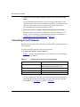
Connecting to the IP Network
When you obtained your router, you also received a cable to connect the router to
your IP network.
To connect the cable from the router to the IP network:
1.
Connect the cable to a router connector.
Table 2-1 lists the standard connectors (also called ports) for connecting the
router to the IP network.
Table 2-1.
Initial Router Connectors to the IP Network
Bay Networks Router
Default Connector
ASN
Any connector on any net module, excluding the
Stack Packet Exchange (SPEX) module
BayStack AN, ANH, and ARN
See the installation guide.
BLN, BCN
First connector on the first link module (slot 2)
System 5000 net modules
See the installation guide.
You can configure any connector on a router for the initial IP connection by
specifying the slot and connector when you quick-start the router with the
installation script (Chapter 4) or the BCC (Chapter 5).
2-4
117342-B Rev. 00
Preparing the Router for Quick-Start
For information about the location of the connector on your router, see the
installation guide that came with your router.
2.
Connect the cable to the network connector.
The network connection depends on your LAN or WAN configuration. For
general information about cables, see the Cable Guide.
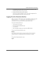
Logging On to the Technician Interface
When you connect to a Bay Networks router and establish a terminal session, the
Technician Interface Login prompt appears. The Technician Interface is a
command-line interface provided with every Bay Networks router.
You use the Technician Interface to:
•
View the router’s file system.
•
Run the Quick-Start installation script.
•
Access the BCC.
•
Enter commands to manage your router and its MIB variables.
To log on to the Technician Interface, enter:
Manager
The Technician Interface displays a prompt consisting of the slot where the
Technician Interface is running, followed by the $ prompt, for example:
2$
To log off the Technician Interface, enter:
logout
117342-B Rev. 00
2-5
Quick-Starting Routers
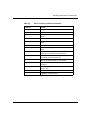
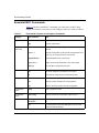
Using Technician Interface Commands
To complete the Quick-Start procedure, you must enter several Technician
Interface commands. Table 2-2 provides a list of the basic Technician Interface
commands you will need. You can also use the Help system to view available
commands.
Technician Interface commands, passwords, and file names are case-sensitive.
You must press the Return key to execute a Technician Interface command.
To display all Technician Interface commands in a brief table, enter:
help help
To display all Technician Interface commands and their associated syntax
requirements, enter
help
Use this command when you know the command’s function, but do not know the
command name or its syntax. Enter the more on command to control Help screen
scrolling.
To display online Help for a specific Technician Interface command, use the help
command, as follows:
help [<command>]
When you enter help, followed by a space and the name of a command, the
console displays a detailed description of the command, along with its syntax
requirements. For example, when you enter help date, the console displays a
detailed description of the date command.
2-6
117342-B Rev. 00
Preparing the Router for Quick-Start
Table 2-2.
117342-B Rev. 00
Basic Technician Interface Commands
Command
Function
cd
Changes the active volume
compact
Reallocates file space on a memory card
copy
Copies a file from one volume to another or to the same
volume
delete
Deletes a file from a volume
dinfo
Displays the volume number, status, and space for each
volume
dir
Displays all files on a volume
format
Erases any existing files on a volume and formats the
volume
more on
Enables the more mode; pauses the display and
prompts you to continue when a screen fills
more off
Disables the more mode; the screen scrolls
automatically without prompting you
partition
Partitions file system media into two volumes
ping -ip <IP_address>
Pings an IP address (for example, 192. xx.xxx.xx) on an
IP network
save
Saves the current software configuration, aliases, or
events to a file
tftp
Transfers a file to or from the router
type
Displays the contents of a file
2-7
Quick-Starting Routers
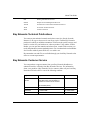
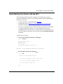
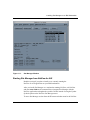
Reviewing the Installation Files
Your router stores its files on memory cards. The nonvolatile file system (NVFS)
running in the router reads and writes to the memory cards for file storage. After
establishing a Technician Interface session, you are ready to display the
Quick-Start installation files and verify that they are available.
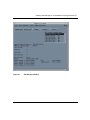
To display and verify the installation files:
1.
Find the memory card location.
Identify the volume where the router’s memory card (volume) resides by
entering:
dinfo
The Technician Interface displays a table showing the memory card’s volume
number and memory statistics. The volume number is equivalent to the slot on
the router. BCNs and BLNs can contain multiple memory cards -- one
memory card per slot.
2.
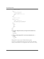
Display the names of the files in the volume by entering:
dir <slot_number>:
<slot_number> is the slot location of the memory card. Include the colon (:)
after the slot number.
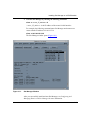
For example,
TBLN>dir 2:
Volume in drive 2: is
Directory of 2:
File Name
Size
Date
Day
Time
--------------------------------------------------------bn.exe
3513155
01/10/98
Mon.
10:03:45
config
132
01/10/98
Mon.
10:03:45
ti.cfg
132
01/10/98
Mon.
10:03:45
install.bat 204323
01/10/98
Mon.
10:03:45
debug.al
12319
01/10/98
Mon.
10:03:45
bcc.help
165960
01/10/98
Mon.
10:03:45
8388608 bytes - Total size
4492587 bytes - Available free space
945812 bytes - Contiguous free space
2-8
117342-B Rev. 00
Preparing the Router for Quick-Start
3.
Note the available free space on the router volume.
You should always make sure you have enough space on the volume to hold
any new files you create or copy.
In the following steps, you verify that the correct router software,
configuration, and installation files are available. These steps may not be
necessary for new routers with the files already installed, although they will
help you become familiar with your router’s files.
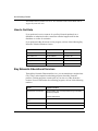
4.
Verify that the directory lists the Quick-Start installation files shown in
Table 2-3.
Table 2-3.
Quick-Start Installation Files
File Name*
File Type
bn.exe
Bootable router software image (see
Table 2-4 for other router images)
config
Default configuration file
debug.al
Alias file
install.bat
Quick-Start installation script file
ti.cfg
Initial configuration file
bcc.help
BCC Help file
* All router files must belong to the same software version. Other files may be in the
directory. Router file names may vary slightly; for example, System 5000 net modules use
the ti_5000.cfg file.
5.
Verify that all router files belong to the same software version.
For example, you should not use a Version 11.00 install.bat script with
BayRS Version 12.10 files.
117342-B Rev. 00
2-9
Quick-Starting Routers
6.
Verify that the directory holds the correct software image for
your router (Table 2-4).
Table 2-4.
Router Software Images
Router
Software Image
AN and ANH*
an.exe
ARN*
arn.exe
ASN*
asn.exe
BCN
bn.exe
BLN
bn.exe
System 5000 net modules
s5000.exe
* See the Quick-Start restrictions for these routers in “About This Guide.”
Booting with the ti.cfg File
To prepare new routers for initial configuration, you first boot the router with the
ti.cfg file. The ti.cfg file is an initial configuration file containing only the minimal
information needed to boot the router. You then run the installation script or use
BCC commands to add configuration information about your first IP interface.
When you complete the Quick-Start procedure, you save your new configuration
information to a file called startup.cfg. Do not edit the ti.cfg file or overwrite it
with another configuration file.
If the installation fails, you must reboot the router with ti.cfg before retrying the
Quick-Start procedure. You also should boot with the ti.cfg file if:
2-10
•
The router is currently booted from a configuration file other than ti.cfg and
you want to reconfigure the router from scratch.
•
You change the initial IP connector (port) that you use to communicate with
the configuration workstation.
117342-B Rev. 00
Preparing the Router for Quick-Start
To boot the router using the ti.cfg file:
1.
Enter the following command:
boot <slot_number>:<image_file> <slot_number>:ti.cfg
<slot_number> identifies the slot where the files reside on the router and
<image_file> is the software image for your router (see Table 2-4).
For example, enter:
boot 2:bn.exe 2:ti.cfg
The router boots and executes its startup procedure.
2.
Establish a new Technician Interface session by entering:
Manager
In Chapter 3, “Preparing Your Network Information,” you will collect and record
the network information needed to complete the Quick-Start procedure.
117342-B Rev. 00
2-11
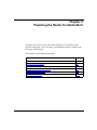
Chapter 3
Preparing Your Network Information
This chapter provides a series of worksheets to help you collect the information
you will need to quick-start the router using either the installation script or BCC
commands. This chapter provides the following information:
Topic
Page
Using the Quick-Start Worksheet
3-2
Using the Quick-Start ATM Worksheet
3-7
Using the Quick-Start Worksheet for WAN Protocols
3-12
Whether you use the installation script or BCC commands, you quick-start the
router as follows:
117342-B Rev. 00
1.
Select an interface and supply information about its connector and circuit.
2.
Configure IP on the interface.
3.
Enable these global communication services (optional):
•
SNMP
•
TFTP
•
FTP
•
Telnet
•
HTTP Server
4.
Save the configuration file as startup.cfg.
5.
Test the initial configuration by pinging the workstation you will use to
continue the configuration.
3-1
Quick-Starting Routers
Many BCC commands and installation script prompts provide default values.
Accept the default values unless you have a reason to make a change. You can skip
optional steps and steps that do not apply to your network.
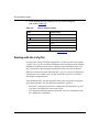
Using the Quick-Start Worksheet
The Quick-Start Worksheet (Table 3-1) provides a summary of the information
you need to complete the Quick-Start procedure. The information can be applied
to either the installation script or BCC commands.
Most customers configure their initial IP interface on Ethernet. The Quick-Start
Worksheet assumes an Ethernet interface in the connector and circuit fields. For
interfaces other than Ethernet, substitute the appropriate connector and circuit
information and complete the rest of the worksheet beginning with the IP
Configuration section.
For other interfaces, see the appropriate configuration guide for more information
about connector and circuit requirements:
•
Configuring Ethernet, FDDI, and Token Ring Services
•
Configuring WAN Line Services
If you plan to use the Quick-Start procedure to configure an ATM interface, go to
“Using the Quick-Start ATM Worksheet” on page 3-7. If you plan to use the
Quick-Start procedure to configure an interface (such as synchronous) that
supports a WAN protocol, see “Using the Quick-Start Worksheet for WAN
Protocols” on page 3-12.
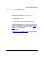
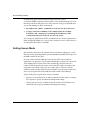
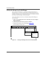
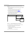
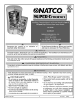
Figure 3-1 shows a sample Ethernet network used in the examples in the
Quick-Start Worksheet. See Appendix A, “Sample Installation Script,” for an
example of the script execution.
3-2
117342-B Rev. 00
Preparing Your Network Information
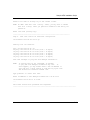
Connect a PC or
ASCll console locally
to view the Technician
Interface and run the Quick-Start installation
script,or the BCC. install.bat
Bay Networks router
Connect the router or BayStream
platform to the IP network.
This router connects from a
QENET Link Module
in Slot 2 using XCVR1
(Ethernet Connector 1)
IP = 192.168.125.34
Subnet Mask = 255.255.255.0
Cosole port in
Slot 1 of AFN, FN, LN,
ALN, CN, BLN, or ASN
or in Slot 7 of BCN
Corporate IP network
Workstation where you'll mange
the router or BayStream platform
remotely, using Site Manager, the BCC
or other configuration tool.
IP Address = 192.32.20.12
QS0005B
Figure 3-1.
117342-B Rev. 00
Network Example for the Quick-Start Worksheet
3-3
Quick-Starting Routers
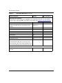
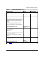
Table 3-1.
Quick-Start Worksheet
Network Information
Example
Your Information
Physical Connector Information
Number of the slot holding the link module for the first
network interface
Slot 2
(QE/NF link module)
Note: For the ASN, also provide the module number (for
example, module 1).
Number of the connector (port) on the link module
Ethernet connector 1
(XCVR1)
Circuit Information
Circuit name (default is provided)
Note: Substitute circuit information for interfaces other
than Ethernet.
E21
IP Configuration
IP address of this initial interface
(Advanced users only: install.bat supports unnumbered
interfaces.)
192.168.125.34
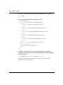
Subnet mask of this initial interface
255.255.255.0
If this interface resides on the same local area network
(LAN) as the workstation you will use to connect to the
router, you have completed the initial IP configuration.
Proceed to add global services.
If the workstation resides on a different network, add an
IP routing protocol first.
No
IP Routing Protocol Information
Choose an IP routing protocol if the configuration
workstation is located on another network:
• RIP
• OSPF
• Static Route
See the following sections for details on the IP routing
protocol you choose to configure.
RIP
(continued)
3-4
117342-B Rev. 00
Preparing Your Network Information
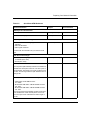
Table 3-1.
Quick-Start Worksheet (continued)
Network Information
Example
Your Information
RIP Configuration
Should RIP listen to the default route to the network or
subnet where the workstation is located?
Yes
OSPF Configuration
OSPF router IP address (if different from this interface)
192.32.156.7
OSPF area address
0.0.0.0
Should you enable Simple Password Authentication?
No
MTU size for OSPF packets (Default, Ethernet Size,
User-defined MTU)
Default
OSPF interface type
(Broadcast, NBMA, Point to Point, Point to MultiPoint)
Note: If there is an existing OSPF configuration on the
network, you must set matching values for the interface
type, Hello Interval, and Dead Interval.
Broadcast (default)
Hello interval (in seconds)
10 (default)
Router dead interval (in seconds)
40 (default)
Router priority
1 (default)
Poll interval
120 (default)
If you are configuring OSPF neighbors, add the IP
address for each neighbor.
Note: Neighbors are defined only if the OSPF interface
type is NBMA. Sample format: 192.32.156.8
Static Route Configuration
Destination network
192.32.90.1
Destination network mask
255.255.255.0
Next-hop address that is in the same subnet as the initial 192.32.4.99
IP interface
(continued)
117342-B Rev. 00
3-5
Quick-Starting Routers
Table 3-1.
Quick-Start Worksheet (continued)
Network Information
Example
Your Information
Global Services Information
These steps set communication services globally for all the interfaces on the router. You can increase
router security by restricting SNMP communities, FTP, and Telnet. See Chapter 7, “Securing the Router.”
Enable SNMP Community Management?
Yes
For each SNMP community, decide whether it is public or public, read-only,
192.32.20.12
private, its read-write access, and IP address of the
manager.
Enable TFTP?
Yes
Default volume where TFTP transactions will take place
2
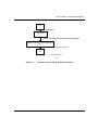
Enable FTP?
Yes
Default volume where FTP transactions will take place
2
Enable Telnet?
Yes
Enable Telnet client?
Yes
Enable Telnet server?
Yes
Enable the HTTP (Web) server?
Yes
Provides embedded Web tools on the router to view
device information. BCC users should enable the HTTP
Server with Site Manager after quick-starting the router.
Workstation Information
IP address of the workstation you will use to configure
the router
3-6
192.32.20.12
117342-B Rev. 00
Preparing Your Network Information
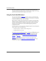
Using the Quick-Start ATM Worksheet
The Quick-Start installation script allows you to configure initial routing services
for the ATM Routing Engine link module in Bay Networks routers. You can then
use Site Manager to refine your configuration.
Use the Quick-Start installation script to add ATM to the router by:
•
Defining the physical link
•
Defining an ATM service record
•
Creating an ATM circuit
•
Adding the initial virtual circuit to the service record (PVCs only)
•
Enabling the IP protocol on the ATM service record
The Quick-Start ATM Worksheet (Table 3-2) contains only the ATM connector,
circuit, and service record information. After you specify the ATM interface, the
Quick-Start script prompts you for the same information found in Table 3-1,
beginning with the IP Configuration section.
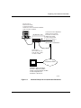
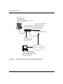
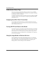
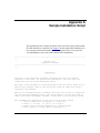
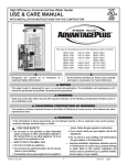
Figure 3-2 shows a sample ATM network used in the examples in the ATM
Quick-Start Worksheet.
See Appendix B, “Sample ATM Installation Script,” for an example of the script
execution.
For more information about the parameters set in the script, see Configuring ATM
Services.
117342-B Rev. 00
3-7
Quick-Starting Routers
Connect a PC or
ASCll console locally
to view the Technician
Interface and run the Quick-Start installation
script,or the BCC. install.bat
Bay Networks router
Connect the router or BayStream
platform to the IP network.
This router connects from a
QENET Link Module
in Slot 2 using XCVR1
(Ethernet Connector 1)
IP = 192.168.125.34
Subnet Mask = 255.255.255.0
Cosole port in
Slot 1 of AFN, FN, LN,
ALN, CN, BLN, or ASN
or in Slot 7 of BCN
Corporate IP network
Workstation where you'll mange
the router or BayStream platform
remotely, using Site Manager, the BCC
or other configuration tool.
IP Address = 192.32.20.12
Figure 3-2.
3-8
Network Example for the Quick-Start ATM Worksheet
117342-B Rev. 00
Preparing Your Network Information
Table 3-2.
Quick-Start ATM Worksheet
Network Information
Example
Your Information
ATM Physical Link Information
Slot number of the link module
4 (ATMC_OC3MM)
Connector number [1]:
1 (ATM1)
Choosing a Service Record Type
Enter ATM Service Record Type [1]:
1. ATM PVC
2. ATM LAN Emulation
3. ATM Logical IP Subnet
1 (ATM PVC)
Continue with the information for your service record
type.
PVC Service Record Type
Enter encapsulation type [1]:
1. LLC/SNAP (RFC 1483)
2. NLPID (RFC 1490)
2 (NLPID (RFC 1490))
For VPI, enter a number from 0 to 255.
0
The VPI (virtual path identifier) number of the initial PVC
identifies the virtual path of the PVC. The VPI is part of
the cell header. The header can contain a maximum of 8
VPI bits. This bit range allows for path identifiers from 0
through 255.
For VCI, enter a valid number in these ranges:
200
- ARE module in a BLN/BCN router:
32 - 65535
- Model 5780 ATM VNR in a Model 5000AH chassis:
130 - 2047
- Model 5782 ATM VNR in a Model 5000BH chassis:
130 - 2047
The VCI (virtual channel identifier) number of the initial
PVC identifies the virtual channel portion of the PVC.
The VCI is part of the cell header and has a length of
16 bits.
(continued)
117342-B Rev. 00
3-9
Quick-Starting Routers
Table 3-2.
Quick-Start ATM Worksheet (continued)
Network Information
Example
Enter circuit name:
(The script recommends a default name.)
ATMSR_1404101.3
Your Information
LAN Emulation Service Record Type
Signaling Version [1]:
1. UNI3.0
2. UNI3.1
2 (UNI3.1)
Do you want Auto Generation of the ATM address? (y/n) No
[y]:
If you choose Auto Generation, router software will use a
combination of the MAC address and the network prefix
obtained from the server to generate a unique ATM
address.
If you do not choose Auto Generation, enter a 7-byte
User Part (Mandatory) and a 13-byte Net Prefix
(Optional) to be combined into a 20-byte ATM address.
Enter User Part (Mandatory), 7 bytes:
Enter Net Prefix (Optional), 13 bytes:
12345677654321
3900000000000000000
0000000
Choose the Emulated LAN Name.
AAA
Press Return to accept the default ELAN name or
type the name of a previously configured ELAN for this
LAN Emulation client to join.
Choose Emulated LAN Type [1]
1. Unspecified
2. IEEE8023
3. IEEE8025
3 (IEEE8025)
Enter circuit name.
(The script recommends a default name.)
ATMSR_1404101.5
(continued)
3-10
117342-B Rev. 00
Preparing Your Network Information
Table 3-2.
Quick-Start ATM Worksheet (continued)
Network Information
Example
Your Information
Logical IP Service Record Type
Signaling Version [1]:
1. UNI3.0
2. UNI3.1
1 (UNI3.0)
Do you want Auto Generation of the ATM address? (y/n) No
[y]:
If you choose Auto Generation, router software will use a
combination of the MAC address and the network prefix
obtained from the server to generate a unique ATM
address.
If you do not choose Auto Generation, enter a 7-byte
User Part (Mandatory) and a 13-byte Net Prefix
(Optional) to be combined into a 20-byte ATM address.
Enter User Part (Mandatory), 7 bytes:
Enter Net Prefix (Optional), 13 bytes:
12345677654321
3900000000000000000
0000000
Choose the ATM ARP Mode.
-Client Mode [Default]
-Server Mode
If you choose the default (Client Mode), you must enter
the ARP Server ATM Address.
Would you like to accept Client Mode for ATM ARP?
(y/n) [y]:
Yes
Enter ARP Server ATM Address in hexadecimal format,
omitting leading 0x/0X.
Enter Network Prefix (Mandatory), 13 bytes:
Enter User Part (Mandatory), 7 bytes:
3900000000000000000
0000000
11111111111111
Refer to Table 3-1, the Quick-Start Worksheet, to continue the initial configuration.
117342-B Rev. 00
3-11
Quick-Starting Routers
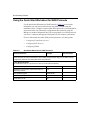
Using the Quick-Start Worksheet for WAN Protocols
Use the Quick-Start Worksheet for WAN Protocols (Table 3-3) to record the
information you will need to enable frame relay, PPP, or SMDS using the
installation script. (Using the script to enable WAN protocols is recommended for
experienced users only.) Normally you implement these protocols using Site
Manager or another configuration tool. The script prompts for a WAN protocol if
you select a connector that supports WAN protocols, for example, synchronous.
For more information about the WAN protocol parameters, see these guides:
Table 3-3.
•
Configuring Frame Relay Services
•
Configuring PPP Services
•
Configuring SMDS
Quick-Start Worksheet for WAN Protocols
Network Information
Example
Your Information
WAN Information
Advanced users can use the Quick-Start script to initially configure frame relay, PPP, or SMDS. See the
configuration guides for more information about the parameters.
Frame Relay Information
(To enable frame relay on a synchronous connector on this initial IP interface)
Enable frame relay on the interface?
Yes
Management protocol that communicates with the
frame relay network
LMI
DLCI addressing types
ADDR Q.922
Frame relay address field length
2 bytes
Frame relay PVC ID
30
(continued)
3-12
117342-B Rev. 00
Preparing Your Network Information
Table 3-3.
Quick-Start Worksheet for WAN Protocols (continued)
Network Information
Example
Your Information
PPP Information
(To enable PPP on a synchronous connector on this initial IP interface)
Enable PPP on the interface?
Yes
IP address of peer connection
192.32.4.2
Enable PPP Echo protocol?
Yes
Number of seconds between transmission of echo
requests
10
Acceptable loss of Echo-Reply packets
3
Enable local authentication protocol?
Yes
Local PAP ID for this interface
192.32.4.1
Local PAP password (optional)
lpwd
Authentication protocol enabled on remote peer?
Yes
Remote peer PAP password
rpwd
Enable Link Quality Reporting (LQR) protocol?
Yes
Enable use of remote peer’s LQR timer?
Yes
Minimum acceptable percentage of inbound packets
90
Minimum acceptable percentage of outbound packets
90
SMDS Information
(To enable SMDS on a synchronous connector on this initial IP interface)
Enable SMDS on the interface?
Yes
Individual address
C1617555433FFFF
Group address
E16175556667FFFF
ARP address
E16175550000FFFF
117342-B Rev. 00
3-13
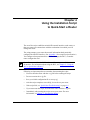
Chapter 4
Using the Installation Script
to Quick-Start a Router
The install.bat script establishes an initial IP network interface on the router so
that your router can communicate with the workstation from which you will
manage the router.
The script prompts you to enter the network information that dynamically
configures the initial IP interface. (See Appendix A for a sample script execution.)
You configure subsequent interfaces with Site Manager, the BCC, or another
router configuration tool.
Note: You can use either the BCC or the install.bat script to establish an initial
IP interface. For information about using the BCC, see Chapter 5, “Using the
BCC to Quick-Start a Router.”
Following are important points to remember about running the script:
117342-B Rev. 00
•
You must boot the router with the ti.cfg file before running the script.
•
Do not overwrite the ti.cfg file.
•
Save your initial configuration file as startup.cfg.
•
After the script completes successfully, do not reboot your router.
•
If the script fails, see “Quick-Start Troubleshooting” on page 4-4.
•
If you must rerun the script, first reboot the router with the ti.cfg file.
•
Immediately after running the script, secure your router. For more
information, see Chapter 7, “Securing the Router.”
4-1
Quick-Starting Routers
Before you start the script, review Table 4-1 for the commands you use to run the
script.
Table 4-1.
Installation Script Commands
Script Action
Your Input
Result
Accept the default value.
Press Return.
Accept the default value the script displays
in brackets, for example, [E21].
Repeat a step to make a
correction.
Press Control-C.
The script displays this prompt:
Terminate script y/n?
Enter n to continue the script and reenter
the current step by deleting the information
you added for that step.
Press Control-C.
The script displays this prompt:
Terminate script y/n?
Enter y to terminate the script and return to
the Technician Interface prompt. Before
rerunning the Quick-Start installation script,
reboot the router using the ti.cfg file.
After booting the router with the ti.cfg file and establishing a new Technician
Interface session, you are ready to run the install.bat installation script.
To run the script:
1.
Access the volume where the installation files reside by entering:
cd <volume_number>:
Include the colon (:) after the volume number.
For example, enter cd 2:
2.
Start the installation script by entering:
run install
Many steps in the installation script provide default values you should accept.
Some steps are optional for your network requirements.
Refer to your Quick-Start worksheet (see Chapter 3) as you respond to the
prompts.
4-2
3.
Select a slot and connector on the router.
4.
Configure IP on the interface.
117342-B Rev. 00
Using the Installation Script to Quick-Start a Router
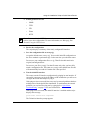
5.
Enable global services for
•
SNMP
•
TFTP
•
FTP
•
Telnet
•
HTTP
Note: You can enable the HTTP Server on the router to access embedded Web
tools to view device information. For more information, see Managing Your
Network Using the HTTP Server.
6.
Review the configuration.
The script displays a summary of the newly configured IP interface.
7.
Save the configuration file as startup.cfg.
Accept the default name, startup.cfg. You save this initial IP configuration to
the file to maintain a permanent copy for the next time you reboot the router.
Do not save your configuration file as ti.cfg. That file should remain in its
original, unconfigured state.
Do not save your file as config. Use that file name only after you have fully
tested a configuration file. The router uses config as the default boot file and
will automatically boot with it if another file is not specified.
8.
Test the initial IP interface.
The router tests the IP interface configuration by pinging its own interface. If
successful, it prompts you for the IP address of the workstation you will use to
configure the router and attempts to ping it.
If the ping test is not successful, the cause may be network problems that have
nothing to do with the Quick-Start installation. To troubleshoot the network
problems, you can leave the ping test by typing Q. See “Quick-Start
Troubleshooting” on page 4-4 for more information.
If the ping test is successful, the initial IP interface is enabled and the script
displays this message:
Quick-Start Installation Completed
The Technician Interface prompt appears.
117342-B Rev. 00
4-3
Quick-Starting Routers
You now have a configuration file named startup.cfg on the router volume that
contains your initial interface. The configuration is active in the router’s memory.
Caution: Do not reboot the router after successfully completing the
Quick-Start procedure. By default, the router reboots with the file named
config, not the startup.cfg file you just created. See Chapter 6, “Completing the
Router Configuration,” for instructions on testing the startup.cfg file before
you save it as config.
Bay Networks recommends that you immediately secure your router to prevent
unauthorized access. See Chapter 7, “Securing the Router,” for information.
Quick-Start Troubleshooting
If the router cannot ping the workstation during the Quick-Start procedure, check
the following:
4-4
•
If the router was able to ping its own interface, and the script prompted you
for the interface of the workstation, you probably have a successful
installation. To be sure, continue with the remaining checks.
•
Check the physical connections.
•
If the workstation is a PC, a supported TCP/IP stack must be running for a
successful ping. See Chapter 8, “Installing Site Manager on a PC,” for
information about TCP/IP stacks, adapters and drivers.
•
Verify the IP address of the router. Enter the show ip circuits command at the
Technician Interface prompt to make sure that the physical interface is up and
that the IP address is correct. For more information about the show command,
see Using Technician Interface Scripts.
•
Verify the IP address and subnet mask address of the configuration
workstation.
117342-B Rev. 00
Using the Installation Script to Quick-Start a Router
•
If the workstation is on a different network, verify that routing is active. Enter
the show ip routes command at the Technician Interface prompt to examine
the routing table and verify that there is a route or a default route to the
network where the workstation is located. For more information about the
show command, see Using Technician Interface Scripts.
Note: If the installation failed and you must rerun the script, first reboot the
router with the ti.cfg file.
117342-B Rev. 00
4-5
Chapter 5
Using the BCC to Quick-Start a Router
The Bay Command Console (BCC) is a command-line interface to your Bay
Networks router. You can configure and manage your BN and AN routers using
BCC commands. This chapter tells you how to use the BCC to quick-start a BN or
AN router and produce an initial configuration file called startup.cfg. Refer to the
following topics:
Topic
Page
Overview of the BCC
5-2
Essential BCC Commands
5-4
Quick-Starting Your Router with the BCC
5-5
Quick-Start Troubleshooting with the BCC
5-13
Note: You can use either the install.bat script or the BCC to establish an initial
IP interface. For information about using the script, see Chapter 4, “Using the
Installation Script to Quick-Start a Router.”
See “Using the Quick-Start Worksheet on page 3-2 to collect the network
information you will need to quick-start the router with BCC commands.
Immediately after quick-starting with the BCC, secure your router.
For information, see Chapter 7, “Securing the Router.”
This chapter provides only the information needed to create an initial interface.
You can continue the configuration with the BCC or another configuration tool,
such as Site Manager.
117342-B Rev. 00
5-1
Quick-Starting Routers
Overview of the BCC
You access the BCC by entering bcc at the Technician Interface prompt. The bcc>
prompt appears, from which you can run any BCC or Technician Interface
command. You enter configuration mode by entering config.
The BCC views the router as a hierarchy of objects and parameters you can
configure either globally for the whole router or individually for each interface.
The BCC always displays a prompt that indicates your current working context (or
location) within the hierarchy.
You start from the root level with the box prompt (box #) and define each interface
and its protocols. To quick-start a router, you configure one Ethernet interface, add
the IP protocol, and add a routing protocol if the workstation is located on a
different LAN than the router (Figure 5-1). Next, you add some global services
that apply uniformly to all slots of a router: SNMP, FTP, TFTP, and Telnet.
Note: If you want to enable the HTTP Server as a global service on the router
after quick-starting with the BCC, use the Site Manager tool.
For more information about the BCC, see:
5-2
•
Using the Bay Command Console (AN/BN Routers)
•
BCC Quick Reference (AN/BN Routers)
•
Release Notes for Router Software Version 12.10
117342-B Rev. 00
Using the BCC to Quick-Start a Router
box
box# ethernet/2/1
ethernet/2/1
ethernet/2/1# ip address 192.168.125.34 mask 255.255.255.0
(address 192.168.125.34 mask 255.255.255.0)
IP
ip/192.168.125.34/255.255.255.0# rip
RIP
rip/192.168.125.34#
BCC0017C
Figure 5-1.
117342-B Rev. 00
Configuring IP and RIP on an Ethernet Interface
5-3
Quick-Starting Routers
Essential BCC Commands
Table 5-1 lists the essential BCC commands you will need to use BCC Help,
change your location, view what you can configure, and review what you added.
Table 5-1.
Essential BCC System and Navigation Commands
Category
BCC Command
Task
System Help
?
List the system commands you can enter.
help
List BCC help features.
?
List the names of all objects, parameters, and commands at
this level.
<object> ?
Show the configuration syntax and list the parameters of an
object you can configure from the current level.
help parameters
Define parameters at the current level.
<parameter> ?
Display values for this parameter of the current object.
help tree
Show the BCC configuration structure.
info
List values assigned to parameters of this object.
lso
Show objects configured at the next (branch) level.
back
Go back one level.
pwc
Show full context, starting from root (box#) level.
box
Return to the top (box) level of router configuration.
Configuration
mode
config
Enter configuration mode.
Configuration
status
show config
Show the total device configuration in BCC syntax.
Other commands
[Control]+p
[Control]+n
Recall previous or next command from the command history
list.
exit
Exit configuration mode; enter exit again to return to the
Technician Interface prompt.
Configuration
mode Help
Navigation
5-4
117342-B Rev. 00
Using the BCC to Quick-Start a Router
Quick-Starting Your Router with the BCC
The following procedure provides a sequence of commands you can use to
quick-start your BN or AN router on an Ethernet network. Before beginning this
procedure you need to:
•
Learn the basic BCC commands listed in Table 5-1.
•
Complete the steps in Chapter 2, “Preparing the Router for Quick-Start,”
including booting the router with the ti.cfg file.
•
For ANs, review the local boot procedure and slot and connector information
in Configuring BayStack Remote Access. By default, the AN router is
configured to boot over the network. To quick-start an AN with the BCC, you
must first change the default boot to local mode with the bconfig config local
command.
To quick-start your router:
1.
Log on to the Technician Interface as Manager.
Login: Manager
Mounting new volume...
Device label:
Directory: 2:
New Present Working Directory: 2:
Welcome to the Backbone Technician Interface
2.
Start the BCC interface by entering bcc.
[2:1]$ bcc
Welcome to Bay Command Console!
* To enter configuration mode, type config
* To list all system commands, type ?
* To exit the BCC, type exit
bcc>
117342-B Rev. 00
5-5
Quick-Starting Routers
3.
Start BCC configuration mode by entering config at the bcc> prompt.
bcc> config
box#
4.
Check the board configuration inside the router:
box# show config
box type freln (BLN router with a FRE controller)
board slot 1
type srml (system resource module in slot 1)
back
board slot 2
type qenf (Quad Synchronous link module in slot 2)
back
board slot 3
type wffddi2m (Multimode FDDI link module in slot
back
board slot 4
type sync (Synchronous link module in slot 4)
back
board slot 5
type dtok (Dual token ring link module in slot 5)
back
back
console portnum 1 (Console connected to port 1)
prompt {[%slot%:1]$ }
auto-manager-script automgr.bat
auto-user-script autouser.bat
back
back
5.
3)
Configure a port on the router for the initial interface by adding an
interface type of Ethernet on a slot with an appropriate board and adding
its first connector:
box# ethernet slot <number> connector <number>
Use the slot and connector number for your router. For example, enter:
ethernet slot 2 connector 1
5-6
117342-B Rev. 00
Using the BCC to Quick-Start a Router
6.
Add IP to this port by entering its IP address and subnet mask.
ethernet/2/1# ip address <ip_address> mask <mask_value>
For example, enter:
ip address 192.168.125.34 mask 255.255.255.0
ip/192.168.125.34/255.255.255.0#
The BCC automatically enables ARP on this interface and adds IP globally to
this router.
If your workstation is on the same LAN as the router, go to step 10. If your
workstation is not on the same LAN as the router, add one of the following
routing protocols:
7.
•
RIP
•
OSPF
•
Static Route
To add RIP as the routing protocol for this IP port, enter:
ip/192.168.125.34/255.255.255.0# rip
Go to step 10.
8.
To add OSPF as the routing protocol for this IP port:
a.
Add an OSPF area:
ip/192.168.125.34/255.255.255.0# ospf area <number>
For example, enter:
ip/192.168.125.34/255.255.255.0# ospf area 0.0.0.0
ospf/192.168.125.34#
b.
View the default values assigned to this OSPF area:
ospf/192.168.125.34# info
on ip/192.168.125.34/255.255.255.0
state enabled
area 0.0.0.0
authentication {}
type broadcast
priority 1
transit-delay 1
retransmission-interval 5
hello-interval 10
dead-interval 40
poll-interval 120
117342-B Rev. 00
5-7
Quick-Starting Routers
metric 1
mtu 1
The type, hello-interval, and dead-interval parameters must match those
of your network. To change these default values, you first need to learn
more about the BCC before proceeding. Refer to Table 5-1 on page 5-4 to
learn about the Help and navigation commands. Use the parameter Help
command (example: type ?) to view the values you can assign and any
further parameters you need to configure. See Using the Bay Command
Console (AN/BN Routers) for more information.
c.
If the OSPF router ID is the same as the IP address of the first router
port, go to step 10.
d.
If the OSPF router ID is different from the IP address of this first
router port, return to root (box) level to change the OSPF router ID
as a global parameter.
ospf/192.168.125.34# box
box#
e.
Move to global IP by entering:
box# ip
ip#
f.
Move to global OSPF by entering:
box# ospf
ip/ospf#
g.
Change the OSPF router ID by entering:
ip/ospf# router-id <ip_address>
For example, enter:
ip/ospf# router-id 192.168.125.10
Go to step 10.
9.
To add a static route to this IP port:
a.
Return to the root (box) level to configure the static route globally.
ip/192.168.125.34/255.255.255.10# box
b.
Move to global IP by entering:
box# ip
5-8
117342-B Rev. 00
Using the BCC to Quick-Start a Router
c.
Add a static route and the next hop by entering:
ip# static-route address <ip_address> mask <mask_value>
next-hop-address <ip_address>
For example, enter:
ip# static-route address 192.168.124.10
mask 255.255.255.0 next-hop-address 192.168.125.35
static-route/192.168.124.10/255.255.255.0/192.168.125.35#
10. Return to root (box) level to configure global system services which affect
all slots, such as SNMP, FTP, Telnet, and TFTP.
<current_level># box
11. Add SNMP globally to the router by entering:
box# snmp
snmp#
12. Specify an SNMP community name, for example, “public.”
snmp# community public
community/public#
13. Define the access level you want for the port for router security.
By default, access is read-only. If you want access to be read-write, enter:
community/public# access read-write
14. Define the workstation that will be the SNMP manager for the router by
entering:
community/public# manager <ip_address>
<ip_address > is the address of the workstation that will be the SNMP
manager. (An address of 0.0.0.0 allows any workstation to be the manager.)
For example, enter:
community/public# manager 192.32.20.12
manager/public/192.32.20.12#
15. Return to root (box) level.
manager/public/192.32.20.12# box
16. Configure Telnet from the root level by entering:
box# telnet
117342-B Rev. 00
5-9
Quick-Starting Routers
17. Add the Telnet client.
telnet# client
client#
18. Go back one level by entering:
client# back
telnet#
19. Add the Telnet server.
telnet# server
20. Return to root (box) level.
telnet# box
21. Add TFTP to the router from the root level.
box# tftp
22. Return to root (box) level.
tftp# box
23. Add FTP to the router from the root level.
box# ftp
24. Save your initial configuration file to the router’s volume as startup.cfg.
box# save config <volume>:startup.cfg
For example, enter:
box# save config 2:startup.cfg
Save the configuration as a file other than config until you can test the
configuration file.
25. Test the initial IP interface by pinging the router’s own interface.
box# ping <ip_address>
For example, enter:
box# ping 192.168.125.34
26. Test the initial IP interface by pinging the workstation where you use the
BCC or other configuration tool.
box# ping <ip_address>
For example, enter:
5-10
117342-B Rev. 00
Using the BCC to Quick-Start a Router
box# ping 192.32.20.12
If either ping is unsuccessful, see “Quick-Start Troubleshooting with the
BCC” on page 5-13.
27. Review your initial router configuration by entering:
box# show config
This command shows the total device configuration in terms of BCC syntax
(commands and data), and returns you to the current context.
For example, enter:
box# show config
box type freln
board slot 1
type srml
back
board slot 2
type qenf
back
board slot 3
type wffddi2m
back
board slot 4
type sync
back
board slot 5
type dtok
back
ethernet slot 2 connector 1
circuit-name E21
ip address 192.168.125.34 mask 255.255.255.0
arp
back
rip
back
back
back
ip
tcp
back
arp
back
rip
back
back
ftp
117342-B Rev. 00
5-11
Quick-Starting Routers
default-volume 2
back
snmp
community label public
access read-write
manager address 192.32.20.12
back
back
back
tftp
default-volume 2
back
console portnum 1
prompt {[%slot%:1]$ }
auto-manager-script automgr.bat
auto-user-script autouser.bat
back
telnet
client
back
server
back
back
back
box#
28. Exit BCC configuration mode by entering the exit command at any
prompt.
box# exit
bcc>
29. When you finish using the BCC, enter the exit command at the bcc>
prompt.
bcc> exit
[2:1]$
Exiting the BCC returns you to the Technician Interface prompt.
You now have a configuration file named startup.cfg on the router volume that
contains your initial interface. The configuration is active in the router’s memory.
5-12
117342-B Rev. 00
Using the BCC to Quick-Start a Router
Caution: Do not reboot the router after successfully completing the
Quick-Start procedure. By default, the router reboots with the file named
config, not the startup.cfg file you just created. See Chapter 6, “Completing the
Router Configuration,” for instructions on testing the startup.cfg file before
you save it as config.
Bay Networks recommends that you immediately secure your router to prevent
unauthorized access. See Chapter 7, “Securing the Router,” for information.
Quick-Start Troubleshooting with the BCC
If the router cannot ping the workstation during the Quick-Start procedure, check
the following:
•
The network could be slow or disabled, or the ping test timed out. Continue
checking the other items.
•
Check the physical connections.
•
If the workstation is a PC, a supported TCP/IP stack must be running for a
successful ping. (See Chapter 8, “Installing Site Manager on a PC,” for
information about TCP/IP stacks, adapters and drivers.
•
Verify the IP address of the router. Enter the show ip circuits command at the
Technician Interface prompt to make sure that the physical interface is up and
that the IP address is correct. For more information about the show command,
see Using Technician Interface Scripts.
•
Verify the IP address and subnet mask address of the configuration
workstation.
•
If the workstation is on a different network, verify that routing is active. Enter
the show ip routes command at the Technician Interface prompt to examine
the routing table and verify that there is a route or a default route to the
network where the workstation is located. For more information about the
show command, see Using Technician Interface Scripts.
Note: If the installation failed and you must rerun the script, first reboot the
router with the ti.cfg file.
117342-B Rev. 00
5-13
Chapter 6
Completing the Router Configuration
This chapter provides an overview of the tools and procedures you can use to
complete the router’s configuration. Refer to the following topics:
Topic
Page
Selecting a Configuration Tool
6-1
Completing the Configuration Procedure
6-2
Communicating with the Router Remotely
6-3
Selecting a Configuration Tool
Bay Networks provides the following tools for configuring your router. See the
Release Notes for information about the platforms, interfaces, and protocols that
each tool supports.
•
The BCC
The BCC is a command-line interface for configuration. You can enhance
your Quick-Start configuration with the BCC for the supported interfaces and
protocols. Configuration files created with the BCC can be modified with
other tools, but first make sure that you save the BCC configuration as a
binary file.
For more information, see Using the Bay Command Console (AN/BN
Routers).
•
Site Manager
Site Manager is a graphical user interface for configuration. If you need to
install Site Manager, see the installation chapter for your workstation later in
this book (Chapters 8 through 12).
117342-B Rev. 00
6-1
Quick-Starting Routers
For information about using Site Manager, see Configuring and Managing
Routers with Site Manager.
•
NETarchitect
NETarchitect integrates Site Manager’s Configuration Manager tool with File
Manager to help you store, distribute, and boot multiple router files.
For more information, see Configuring and Maintaining Networks with the
NETarchitect System in the Optivity® documentation set.
•
Quick2Config
Quick2Config is an easy-to-use configuration tool for the ASN and the
BayStack AN and ANH routers.
For more information, see Configuring Your Router Using the Quick2Config
Tool in the Quick2Config documentation set.
•
Technician Interface
The Technician Interface is a command-line interface for managing routers
and setting MIB values. (BCC commands are gradually replacing Technician
Interface functions.)
For more information, see Using Technician Interface Software.
•
HTTP Server
The HTTP Server provides embedded Web tools on the router to view device
information. It also provides some configuration functions like port disabling.
You enable the HTTP Server on the router from install.bat or Site Manager.
For more information, see Managing Your Network Using the HTTP Server.
Completing the Configuration Procedure
The Quick-Start procedure creates a configuration file named startup.cfg on the
router. The initial configuration is active in the router’s memory.
You use a configuration tool to add protocols and ports to the initial configuration.
After testing the new configuration, you save it as config, the router’s default
configuration file.
6-2
117342-B Rev. 00
Completing the Router Configuration
Note: Be sure to create and test a new config file as soon as you complete the
Quick-Start procedure. By default the router boots with config unless you
specify another file. It is important that you always keep a working, tested file
named config to ensure that the router operates correctly.
The following outlines the general procedure for modifying the initial
configuration with your chosen tool:
1.
Make a backup copy of the startup.cfg file using the configuration tool.
2.
Modify the startup.cfg file by adding interfaces and protocols.
3.
Save the modified configuration as a test file, for example, test.cfg.
4.
Boot the router with the test configuration file.
5.
Verify that the router’s new configuration works correctly.
6.
Save the verified configuration file as config.
Always save a copy of the current config file before you overwrite it.
Communicating with the Router Remotely
In addition to the network connections you make to the router with tools such as
Site Manager, you can also communicate with the router remotely using:
•
Telnet connections
•
Out-of-band connections
•
Memory card distribution
Telnet Connections
You can manage a router from a remote workstation by establishing a Telnet
connection and using the router’s Technician Interface and the BCC. See Using
Technician Interface Software for information about establishing a Telnet session.
117342-B Rev. 00
6-3
Quick-Starting Routers
Out-Of-Band Connections
As a backup method of reaching the Technician Interface and the BCC, you can
also access the router remotely through the modem port. This connection is called
a remote out-of-band connection. Out-of-band refers to the fact that it is not
dependent on a network connection, so that you can still communicate with your
router even if the network is down.
See Using Technician Interface Software for information about modem
connections and your installation guide for information abut connecting modems.
Router Memory Card Distribution
You can also distribute files to the router on memory cards. Some network
managers modify router files at a central location, save them to a memory card,
and then distribute the card to a remote office. Be sure to read the safety warnings
in the router’s installation guide before changing memory cards.
6-4
117342-B Rev. 00
Chapter 7
Securing the Router
Bay Networks recommends that you immediately secure your router to prevent
unauthorized access. This chapter provides an overview of the security features
and services of you can use:
117342-B Rev. 00
Topic
Page
Assigning a Password to the Technician Interface
7-2
Securing New Routers with the BCC or the Installation Script
7-3
Setting Global IP Access Policies with the BCC
7-3
Restricting Read/Write Access with SNMP Communities
7-3
Setting Secure Mode
7-4
Authentication Failure Traps
7-6
Assigning SecurID to Telnet Connections
7-6
Turning Off FTP and Telnet on the Router
7-6
Using the Image Builder to Remove Services
7-6
Restricting Access to the HTTP Server
7-7
Configuring Data Encryption Services
7-7
Configuring RADIUS
7-8
Installing BaySecure FireWall-1
7-8
7-1
Quick-Starting Routers
Assigning a Password to the Technician Interface
The Technician Interface provides local and remote access to your router’s file
system. You should immediately add a security password for the administrator of
the router’s Technician Interface.
1.
Enter the password command for a manager:
password Manager
The console displays the following message:
Changing password for Manager
Old password:
2.
Because there is no old password, press the Return key.
New Password:
3.
Enter the new password.
The password can have from 0 to 16 alphanumeric characters.
4.
Reenter your password at the prompt.
Retype new password:
The console displays the following message:
Manager password changed
See Using Technician Interface Software for instructions on setting passwords for
users and additional information.
7-2
117342-B Rev. 00
Securing the Router
Securing New Routers with the BCC or the Installation Script
Although you can quick-start BN and AN routers using either the BCC or the
install.bat script, the BCC provides an operational advantage if you have security
concerns.
By default, the BCC adds read-only access to the router. You must explicitly
configure write access. After you quick-start the router, you can immediately use
the BCC to change the global IP access policies and secure the router.
The install.bat script adds read-write access by default. You must then establish a
Site Manager (or other configuration tool) session before you can add additional
security for IP services.
See “Setting Global IP Access Policies with the BCC” and “Restricting
Read/Write Access with SNMP Communities” for additional information.
Setting Global IP Access Policies with the BCC
The BCC allows you to create global IP access policies for BN and AN routers
that control access to specific IP services, including Telnet, FTP, TFTP, and
SNMP.
You define a policy and its actions by setting BCC parameters. See the appendix
“Configuring Global IP Policies” in Configuring IP Utilities for more
information.
Restricting Read/Write Access with SNMP Communities
You can use either Site Manager or the BCC to control SNMP access to the router.
You should restrict read/write access to the router as soon as possible by
reconfiguring the SNMP communities.
When you add SNMP with the BCC, access is defined by default as read-only.
You should immediately add managers to control any write access you explicitly
add.
117342-B Rev. 00
7-3
Quick-Starting Routers
By default, the Quick-Start installation script (install.bat) creates
a read/write SNMP community named “public” with a wildcard manager (0.0.0.0)
that allows universal read/write access. Bay Networks strongly recommends that
you use Site Manager or BCC commands to:
1.
Reconfigure the “public” community as read-only for universal access.
2.
Create a read/write community with a unique name (for example,
EASTBAY) and a manager list containing the IP addresses of the
workstations that need read/write access to the router.
See Configuring SNMP, BootP, DHCP, and RARP Services for more information
about configuring SNMP. See Using the Bay Command Console (AN/BN Routers)
for information about BCC commands.
Setting Secure Mode
Bay Networks routers have an optional security mechanism, called secure mode,
that uses an encryption algorithm to prevent unauthorized SNMP SET requests to
the MIB variables of the router.
In secure mode, when Site Manager issues the first SET request within an
application, you must enter a key to allow Site Manager to operate in secure mode.
A Site Manager SET request to the router includes the encrypted value of a
counter. When the agent on the router receives the SET request, it compares the
encrypted value with the value of its own counter plus 1. If the two counters
match, the agent considers the SET request authentic, increments the counter by 2,
stores it in encrypted form in the MIB, and sends it back to Site Manager.
Secure mode protects against these security violations:
7-4
•
Message stream modification, in which an intruder reorders, delays, or replays
SET requests to specify unauthorized management settings
•
Masquerade operations, in which an intruder assumes the IP address of an
authorized user to specify unauthorized management settings
117342-B Rev. 00
Securing the Router
Secure mode does not protect against the following security violations, which are
beyond the scope of this proprietary interim security system:
•
Modification of information, in which an intruder intercepts a packet,
modifies its contents, and reinserts it into the message stream before the
agent’s counter increments
•
Disclosure, in which an intruder observes which variables are being set
Enabling the security mechanism only minimally affects router performance. The
security mechanism has no effect on the ability of Site Manager, or of any SNMP
network manager, to monitor the router by performing GET, GET-NEXT, or trap
functions.
Specifying Secure Mode
To set the router to secure mode:
1.
Set up private, read-write SNMP communities for your router using Site
Manager.
You cannot use public communities with secure mode. See
“Restricting Read/Write Access with SNMP Communities” on page 7-3
for instructions on changing SNMP communities.
2.
Using the Technician Interface on the router, enter the following
command:
wfsnmpmode 3
3 indicates that the router should operate using the proprietary security
mechanism.
3.
Specify a password key for the encryption algorithm to use when it
encrypts the security counters by entering the following command:
wfsnmpkey <key>
<key> is the string of ASCII characters that you select to make up the
encryption code for this router. The key can have up to six characters. The
encryption algorithm uses the attributes of the key (size, range, and value) in
the encryption process.
To turn off secure mode and revert to the default SNMP community security mode
(called trivial mode), enter the following Technician Interface command:
wfsnmpmode 1
117342-B Rev. 00
7-5
Quick-Starting Routers
Authentication Failure Traps
The router generates an authentication failure trap when it receives an SNMP
message from an SNMP manager falsely claiming to be in a particular community
or specifying an unknown community.
To enable the authentication failure trap feature on the router, configure an SNMP
community manager to receive the trap. (See Configuring SNMP, BootP, DHCP,
and RARP Services.)
Assigning SecurID to Telnet Connections
You can enable password protection for your Telnet connections to the router
using SecurID services. See Using Technician Interface Software for information
about enabling SecurID services.
Turning Off FTP and Telnet on the Router
If you have local access to your router or do not need network access to maintain
your router, consider turning off FTP and Telnet. Your router will be more secure
without network access and will require less memory and processing overhead.
You can turn these services off using the BCC or Site Manager. See Configuring
IP Utilities for instructions.
Using the Image Builder to Remove Services
The Image Builder tool provided with Site Manager allows you to modify the
router software image. You can use the Image Builder tool to remove unwanted
services and protocols, such as FTP, from the router. See Configuring and
Managing Routers with Site Manager for more information.
7-6
117342-B Rev. 00
Securing the Router
Restricting Access to the HTTP Server
The HTTP Server uses the following Technician Interface logins and passwords to
restrict access:
•
The Manager login allows access to all services. To sign on as Manager on the
HTTP Server, you must first add a password for Manager using the
Technician Interface (see “Assigning a Password to the Technician Interface”
on page 7-2).
•
The User login prohibits access to the SNMP community page and prevents
changes to the ports and protocols on the router. A password is not required.
Configuring Data Encryption Services
Bay Networks data encryption services enable you to protect sensitive traffic on
your network. Encryption prevents unauthorized persons from reading, changing,
or replaying data that travels between Bay Networks routers.
Data encryption services include:
•
Software-based encryption for PPP dedicated links for the BN, AN, ARN, and
ASN routers; System 5000 router modules; and all serial interfaces. This
includes encryption on multiline and multilink.
•
Software-based encryption for frame relay circuits that have one permanent
virtual circuit (PVC) per service record. This include encryption on multiline.
•
Encryption configurable on a line or circuit basis.
•
Encryption with or without data compression.
You can configure PPP dial backup for a frame relay circuit that uses data
encryption. Be aware, however, that if the primary circuit fails, data that travels
over the backup circuit is unencrypted.
See Configuring Data Encryption Services for more information.
117342-B Rev. 00
7-7
Quick-Starting Routers
Configuring RADIUS
Remote Authentication Dial-In User Service (RADIUS) defines a method of
centralizing authentication and accounting information for networks with many
remote dial-in users. By placing authentication and accounting functions in one
central location, you can improve security and better manage large networks.
In a network using RADIUS, the router is the RADIUS client. The client is the
connection point between remote users and a RADIUS server. The server has the
information that it needs to identify remote users and to keep accounting
information for each call.
For more information, See Configuring RADIUS.
Installing BaySecure FireWall-1
For additional network security, Bay Networks provides BaySecure™ FireWall-1
software. This software integrates the Check Point FireWall-1 network security
engine from Check Point Software Technologies Ltd into the Bay Networks router
software to create a security system that provides fully secure, antispoofing
communication for all Internet applications and services. For more information,
see Configuring BaySecure FireWall-1.
To purchase or learn more about BaySecure FireWall-1 software, call Bay
Networks Sales at 1-800-8-BAYNET.
7-8
117342-B Rev. 00
Chapter 8
Installing Site Manager on a PC
Site Manager is a graphical user interface for router configuration and
management over an IP network. To install Site Manager on a PC running
Windows 95, review the following topics:
Topic
Page
System Requirements
8-1
Updating TCP/IP, Network Adapters, and Drivers
8-2
Loading and Starting Site Manager Software
8-4
System Requirements
To run Site Manager, your PC must meet the following hardware and software
requirements:
117342-B Rev. 00
•
486 PC (Pentium PC recommended)
•
Microsoft Windows 95
•
16 MB of RAM (minimum)
•
60 MB of free disk space
•
Microsoft TCP/IP for Windows 95 and compatible network adapters and
driver
•
CD-ROM drive
•
VGA monitor (SuperVGA monitor recommended)
8-1
Quick-Starting Routers
Updating TCP/IP, Network Adapters, and Drivers
Site Manager Version 6.10 for Windows 95 requires the Microsoft TCP/IP
protocol stack provided with Windows 95 and a compatible network adapter and
driver.
If you purchased a PC with Windows 95 and a network adapter installed, most
likely you have the correct TCP/IP protocol stack, network adapter, and driver.
Go to “Testing TCP/IP” on page 8-3.
If you need to upgrade from Windows 3.1 to Windows 95, first uninstall any
existing 16-bit TCP/IP stack, such as Distinct TCP/IP Run Time. Otherwise,
Windows 95 will install that stack instead of the Microsoft TCP/IP protocol stack.
If you already upgraded from Windows 3.1 to Windows 95 and the upgrade kept
an existing 16-bit TCP/IP stack, such as Distinct TCP/IP Run Time, you must
uninstall the 16-bit TCP/IP stack before adding the Microsoft TCP/IP protocol
stack.
To uninstall a 16-bit TCP/IP stack, refer to the TCP/IP provider’s documentation
and support for help in removing the stack’s path statements, services file, and
WINSOCK.DLL files dated prior to July 11, 1995 (the date of the
WINSOCK.DLL file installed by Windows 95).
To add or update a protocol, network adapter, or driver, refer to the appropriate
documentation and support from Microsoft and the adapter manufacturer.
Protocol and driver updates are added from the Network option of the Control
Panel. New network adapters and their drivers are added from the Add New
Hardware option of the Control Panel.
Windows 95 attempts to match a driver to the network adapter installed on your
PC. If Windows 95 cannot match a compatible driver, you need to update the
driver. Contact the adapter manufacturer for the latest drivers. Microsoft and other
Windows 95 Web sites may also have updated drivers.
Refer to Microsoft Windows 95 Resource Kit for additional technical information
about these issues. A hard copy is available from Microsoft Press.
8-2
117342-B Rev. 00
Installing Site Manager on a PC
Preparing the Network Control Panel
In addition to obtaining the supported TCP/IP protocol, network adapters, and
drivers, you need to configure the Network option of the Control Panel with the
required information for your network.
Choose Control Panels > Network > TCP/IP > Properties to display the TCP/IP
properties menu, which contains tab windows for the following information:
•
IP address
•
WINS configuration
•
Gateway
•
Bindings
•
Advanced
•
DNS configuration
Refer to your Windows 95 Help or documentation for information about setting
the parameters in these windows.
Testing TCP/IP
Before installing Site Manager, send a ping request to the router to make sure your
computer’s TCP/IP function is running.
1.
From the Start Menu, choose Programs > MS-DOS Prompt.
2.
Enter the following command to ping your router:
ping <ip_address>
<ip_address> is the IP address of your router.
Messages appear at the prompt indicating whether replies were received.
Replies verify that your Microsoft TCP/IP protocol stack is functional.
117342-B Rev. 00
8-3
Quick-Starting Routers
Loading and Starting Site Manager Software
Caution: If you are reinstalling Site Manager, be aware that the installation
will overwrite the c:\windows\siteman.ini file. If you are installing multiple
versions of Site Manager on the same PC, make a copy of this file and later
edit the new file to include the information about the other versions.
To install Site Manager software from a CD:
1.
Insert the Bay Networks Site Manager CD into your CD-ROM drive.
2.
Access the Run window by choosing Run from the Start menu.
3.
Type the CD-ROM drive, path, and executable file:
<CD-ROM drive> :\ms_win\setup.exe
The D: drive is usually the CD-ROM drive.
4.
Click on OK.
You can also use the Browse button, Windows Explorer, or My Computer to
select the CD-ROM drive and the path to the ms_win directory and then click
on setup.exe.
The installation script prompts you for the directory in which you want to
install Site Manager.
5.
Enter the directory in which to install Site Manager, or accept the default,
c:\WF.
The Site Manager files are installed in the chosen directory. When the
installation is finished, the following prompt appears:
Create windows program group/items automatically?
6.
To add Site Manager as a selection on the Start > Programs menu, click
on Yes.
This option allows you to start Site Manager after installation by choosing
Start > Programs > Site Manager > PC_Site Manager.
If you do not want Site Manager to appear as a selection on the Start >
Programs menu, click on No.
The following prompt appears:
Do you want to start Site Manager now?
8-4
117342-B Rev. 00
Installing Site Manager on a PC
7.
Click on Yes at the prompt to start Site Manager.
The Router Connection Options window opens.
8.
Enter the IP address and SNMP community of the initial router interface
that you created during the Quick-Start procedure.
9.
Click on OK to display the main Site Manager window (Figure 8-1).
After you successfully install and start Site Manager, see Configuring and
Managing Routers with Site Manager for more information.
Figure 8-1.
117342-B Rev. 00
Site Manager Window
8-5
Chapter 9
Installing Site Manager
on a Workstation Running Windows NT
Site Manager is a graphical user interface for router configuration and
management over an IP network. To install Site Manager on a workstation running
Windows NT, review the following topics:
Topic
Page
System Requirements
9-1
Preparing the Network Control Panel
9-2
Testing TCP/IP
9-2
Loading and Starting Site Manager Software
9-3
System Requirements
Site Manager for the Windows NT operating system runs in 16-bit mode. Your
workstation must meet the following hardware and software requirements:
117342-B Rev. 00
•
486/100 workstation (Pentium workstation recommended)
•
Microsoft Windows NT Version 4.0
•
16 MB of RAM (minimum)
•
60 MB of free disk space
•
TCP/IP Protocol and compatible network adapters and driver
•
CD-ROM drive
•
VGA monitor (SuperVGA monitor recommended)
9-1
Quick-Starting Routers
Preparing the Network Control Panel
You need to configure the Network option of the Control Panel with the required
information for your network. Refer to Windows NT Help and documentation or
commercial publications such as Microsoft Windows NT Resource Kit if you need
technical information about setting the Network options.
For the TCP/IP Protocol option, you need to set the following information:
•
IP address
•
DNS
•
WINS address
•
Routing
Testing TCP/IP
Before installing Site Manager, send a ping request to the router to make sure your
computer’s TCP/IP function is running.
1.
From the Start Menu, choose Programs > MS-DOS Prompt.
2.
Enter the following command to ping your router:
ping <ip_address>
<ip_address> is the IP address of your router.
Messages appear at the prompt indicating whether replies were received.
Replies verify that your Microsoft TCP/IP protocol stack is functional.
9-2
117342-B Rev. 00
Installing Site Manager on a Workstation Running Windows NT
Loading and Starting Site Manager Software
Caution: If you are reinstalling Site Manager, be aware that the installation
will overwrite the c:\windows\siteman.ini file. If you are installing multiple
versions of Site Manager on the same workstation, make a copy of this file and
later edit the new file to include the information about the other versions.
To install Site Manager software from a CD:
1.
Insert the Bay Networks Site Manager CD into your CD-ROM drive.
2.
Access the Run window by choosing Run from the Start menu.
3.
Type the CD-ROM drive, path, and executable file:
<CD-ROM drive> :\ms_win\setup.exe
The D: drive is usually the CD-ROM drive.
4.
Click on OK.
You can also use the Browse button, Windows Explorer, or My Computer to
select the CD-ROM drive and the path to the ms_win directory and then click
on setup.exe.
If the TCP/IP services file is not located in the default directory,
(C:\WINNT\system32\drivers\etc), the installation script prompts you for the
directory.
5.
If prompted to do so, enter the path to the directory where the TCP/IP
services file is located.
Note: The TCP/IP services file is different from the services.exe file.
The installation script prompts you for the directory in which you want to
install Site Manager.
6.
Enter the directory in which to install Site Manager, or accept the default,
c:\WF.
The Site Manager files are installed in the chosen directory. When the
installation is finished, the following prompt appears:
Create windows program group/items automatically?
117342-B Rev. 00
9-3
Quick-Starting Routers
7.
To add Site Manager as a selection on the Start > Programs menu, click
on Yes.
This option allows you to start Site Manager after installation by choosing
Start > Programs > Site Manager > PC_Site Manager.
If you do not want Site Manager to appear as a selection on the Start >
Programs menu, click on No.
The following prompt appears:
Do you want to start Site Manager now?
8.
Click on Yes at the prompt to start Site Manager.
The Router Connection Options window opens.
9.
Enter the IP address and SNMP community of the initial router interface
that you created during the Quick-Start procedure.
10. Click on OK to display the main Site Manager window (Figure 9-1).
After you successfully install and start Site Manager, see Configuring and
Managing Routers with Site Manager for more information.
9-4
117342-B Rev. 00
Installing Site Manager on a Workstation Running Windows NT
Figure 9-1.
117342-B Rev. 00
Site Manager Window
9-5
Chapter 10
Installing Site Manager on a SPARCstation
Site Manager is a graphical user interface for router configuration and
management over an IP network. To install Site Manager on a SPARCstation,
review the following topics:
117342-B Rev. 00
Topic
Page
System Requirements
10-2
Setting Up the SPARCstation
10-2
Loading Site Manager Software
10-3
Setting Up Site Manager User Accounts
10-5
Verifying Site Manager Installation
10-6
Starting Site Manager
10-6
10-1
Quick-Starting Routers
System Requirements
To run Site Manager, your SPARCstation must meet the following hardware and
software requirements:
•
•
•
Supported workstations
--
SPARCstation 10, 20
--
UltraSPARCstation
Supported operating systems
--
SunOS 4.1.4
--
Solaris 2.5.1 and 2.6
Window environment for Solaris
--
CDE 1.0.1
--
OpenWindows 3.5
•
32 MB of RAM (64 MB recommended)
•
85 MB of disk space
•
32 MB of swap space
•
Network adapter appropriate for your network
•
CD-ROM drive
Setting Up the SPARCstation
Before you load Site Manager software on your SPARCstation, do the following:
1.
Log in to the SPARCstation as root (or enter su root).
2.
Edit the /etc/services system file (on each host device) to include the
following lines at the bottom of the file:
snmp161/udp
snmp-trap162/udp
You can use any text editor to edit the file. The first line associates the service
name snmp with UDP port number 161 on this host device. The second line
associates the service name snmp-trap with UDP port number 162.
3.
10-2
Save /etc/services and exit from the text editor.
117342-B Rev. 00
Installing Site Manager on a SPARCstation
Loading Site Manager Software
Load Site Manager software on the SPARCstation as follows:
•
Mount a CD-ROM drive.
•
Install the software.
•
Unmount the drive.
Note: The command for mounting the CD-ROM drive varies depending on
your system, for example, the number of CD-ROM drives. If the suggested
mount command fails, consult your operating system documentation.
Mounting a CD-ROM Drive on SunOS and Solaris
To mount a CD-ROM drive:
1.
Insert the appropriate CD and drive tray into the CD-ROM drive.
2.
Log in as root by entering:
su
3.
At the password prompt, enter your root password.
4.
If a subdirectory or file system does not already exist for the CD, create
one by entering:
mkdir /cdrom
5.
Mount the CD-ROM drive.
•
For SunOS, enter:
mount -r -t hsfs /dev/sr0 /cdrom
sr0 is the CD-ROM drive’s address.
•
For Solaris, the Volume Manager automatically mounts the CD onto
/cdrom/release_1210_610. If the CD does not automatically mount, stop
the vold daemon and manually mount the drive.
a.
Display the daemon’s process ID by entering:
ps -ef | grep vold
b.
If there is a process running for the vold daemon, enter:
kill <process_id>
117342-B Rev. 00
10-3
Quick-Starting Routers
c.
Mount the CD-ROM drive by entering:
mount -F hsfs -o ro /dev/dsk/c0t6d0s0 /cdrom
c0t6d0s0 is the CD-ROM drive’s address.
Installing the Software
To install Site Manager software:
1.
As root, change to the CD-ROM mountpoint.
cd /cdrom
If you use Solaris and are running the vold daemon, enter:
cd /cdrom/release_1210_610
2.
Run the script to load Site Manager software by entering:
. /INSTALL.SH
Type the command in all uppercase letters. The installation process does the
following:
•
Lists the directories that contain enough space to install Site Manager.
You can then specify the directory you want to use.
•
Executes the Site Manager installation script, WFSM_INSTALL.
When the installation is finished, your workstation displays the message:
Site Manager Installation Complete.
Additional messages about your SPARCstation environment may appear.
Unmounting the CD-ROM Drive
To unmount a CD-ROM drive, enter:
cd /
umount /cdrom
For CDs automatically mounted on a CD-ROM drive, enter:
cd /
eject cdrom
10-4
117342-B Rev. 00
Installing Site Manager on a SPARCstation
Setting Up Site Manager User Accounts
To set up individual Site Manager users on the SPARCstation:
1.
Press Control-d to exit the root account.
2.
Log in to the user account.
3.
If this is the first time you installed Site Manager, create the directory in
which to install the Site Manager Image Builder application by entering:
mkdir $HOME/.builder_dir
4.
Edit the user account setup file as follows:
•
If you use the C shell (csh) or clones, add the following lines to .cshrc:
set path = ($path /usr/wf/bin)
setenv WF_SMPATH /usr/wf
setenv SMTERM X
setenv SM_CONFIGS <directory where config files are stored >
setenv BUILDER_DIR $HOME/.builder_dir
Note: If the shell variable path is already set in some other line of the .cshrc
file, add these new lines immediately after the last set path line.
•
If you use the Bourne shell (sh) or clones, add the following lines to
.profile:
PATH=$PATH:/usr/wf/bin
WF_SMPATH=/usr/wf
SMTERM=X
SM_CONFIGS=<directory where config files are stored >
BUILDER_DIR=$HOME/builder_dir
export WF_SMPATH SMTERM SM_CONFIGS BUILDER_DIR
5.
Log out of the user account.
Repeat steps 1 through 5 for each user account that needs to run Site Manager.
117342-B Rev. 00
10-5
Quick-Starting Routers
Verifying Site Manager Installation
To verify the Site Manager installation and environment:
1.
Log in to a user account that you set up for Site Manager.
2.
Start the window environment (CDE or OpenWindows).
3.
Verify the Site Manager installation by entering:
wfchkinst
If the installation was successful, the workstation displays the message:
Installation is complete and correct!
4.
Verify the Site Manager environment by entering:
wfchkenv
If the environment is correctly configured, the workstation displays the
message:
Your environment seems to have been set up correctly.
Repeat steps 1 through 4 for each user account that has Site Manager installed.
Note: If your environment variables are incorrect, you receive an error
message to reset the variables.
Starting Site Manager
To start the Site Manager application:
1.
Log in with a user account that has been set up for Site Manager
operation.
2.
Start the window environment, for example, CDE.
3.
Change to a directory with read/write privileges where Site Manager can
save configuration and other files.
For example, the following command changes to the directory
/home/siteman/config_files:
cd /home/siteman/config_files
10-6
117342-B Rev. 00
Installing Site Manager on a SPARCstation
4.
Activate Site Manager by entering the following command:
wfsm -a <router_IP_address > &
<router_IP_address> is the IP address of the router’s initial interface.
For example, the following command starts Site Manager and connects to a
router with the IP address 192.168.125.34:
wfsm -a 192.168.125.34 &
The Site Manager window opens (Figure 10-1).
Figure 10-1.
Site Manager Window
After you successfully install and start Site Manager, see Configuring and
Managing Routers with Site Manager for more information.
117342-B Rev. 00
10-7
Quick-Starting Routers
Starting Site Manager from SunNet Manager
After you install Site Manager on a workstation running SunNet Manager or
Domain Manager, you must exit SunNet Manager or Domain Manager and run
the snm -i command from the command line to integrate Site Manager and update
the schema in SunNet Manager or Domain Manager.
To start a Site Manager session on a workstation running SunNet Manager or
Domain Manager:
1.
Open a view containing the icon of a router that you want to configure
using Site Manager.
2.
Click on the icon of the router you want to configure.
3.
From the Tools menu, choose Site Manager (Figure 10-2).
The Site Manager window opens.
IP Internet
File
Edit
View
Locate
Options
Monitor
Test
Tools
Help
Administer
MIB Application Builder: SNMP...
MIB Browser: SNMP...
Graph Collected Data: SNMP
Data Collection & Thresholds: SNMP...
Filter Editor...
Site Manager
Site Manager...
Failing Resource Display...
Configuration (dynamic)...
Mail...
Statistics Manager...
Print...
Trap Monitor...
Remote Files Manager...
Event Files...
Update Symbols...
U.2844.4
Figure 10-2.
10-8
Starting a Site Manager Session from SunNet Manager
117342-B Rev. 00
Installing Site Manager on a SPARCstation
Starting Site Manager from OpenView
Read this section if you plan to install or are currently running the HP OpenView
application on your SPARCstation.
After you install Site Manager on a workstation running HP OpenView, exit
HP OpenView and enter ovw -fields at the command line to integrate Site
Manager with the OpenView application and to update the symbols. Do this
instead of using the Update Symbols option on the OpenView Site Manager menu.
To start a Site Manager session from the IP Internet window menu bar in
OpenView:
1.
Open a view containing the icon of the router that you want to configure
using Site Manager.
The IP Internet window opens with a map of your internetwork.
2.
Click on the icon of the router you want to configure.
3.
From the Tools menu, choose Site Manager (Figure 10-3).
The Site Manager window opens with a list of tools.
4.
If the Site Manager tools are dimmed, delete the router from OpenView
so that it can be rediscovered.
IP Internet
File
Edit
View
Locate
Options
Monitor
Test
Tools
Help
Administer
MIB Application Builder: SNMP...
MIB Browser: SNMP...
Graph Collected Data: SNMP
Data Collection & Thresholds: SNMP...
Filter Editor...
Site Manager
Site Manager...
SynOptics Application
Configuration (dynamic)...
Failing Resource Display...
Statistics Manager...
Mail...
Trap Monitor...
Print...
Remote Files Manager...
Event Files...
Update Symbols...
U.2844.2
Figure 10-3.
117342-B Rev. 00
Starting a Site Manager Session from OpenView
10-9
Quick-Starting Routers
If you install OpenView after you install Site Manager software, follow these
steps to integrate Site Manager with the OpenView application.
1.
Change to the /usr/wf directory.
2.
Reexecute the Site Manager installation script by entering:
. / WFSM_INSTALL
Follow these steps any time you reinstall OpenView.
10-10
117342-B Rev. 00
Chapter 11
Installing Site Manager on an IBM Workstation
Site Manager is a graphical user interface for router configuration and
management over an IP network. To install Site Manager on an IBM RS/6000 or
PowerPC workstation, review the following topics:
117342-B Rev. 00
Topic
Page
System Requirements
11-2
Loading Site Manager Software
11-2
Setting Up Site Manager User Accounts
11-4
Verifying Site Manager Installation
11-5
Starting Site Manager
11-6
11-1
Quick-Starting Routers
System Requirements
To run Site Manager, your IBM workstation must meet the following hardware
and software requirements:
•
•
Supported workstations
--
RS/6000 340, 370
--
PowerPC
Supported operating system
--
•
IBM AIX Version 4.2
Window environment
--
CDE 1.0.1
--
AIX Motif 1.2
•
32 MB of RAM (64 MB recommended)
•
80 MB of disk space
•
32 MB of swap space (64 MB recommended -- use 96 MB of swap space with
the NetView for AIX application)
•
Network adapter appropriate for your network
•
CD-ROM drive
Loading Site Manager Software
Load the Site Manager software on the IBM workstation as follows:
•
Mount a CD-ROM drive.
•
Install the software.
•
Unmount the drive.
Note: The command for mounting the CD-ROM drive varies depending on
your system, for example, the number of CD-ROM drives. If the suggested
mount command fails, consult your operating system documentation.
11-2
117342-B Rev. 00
Installing Site Manager on an IBM Workstation
Mounting a CD-ROM Drive
To mount a CD-ROM drive:
1.
Insert the appropriate CD and drive tray into the CD-ROM drive.
2.
Log in as root by entering:
su
3.
At the password prompt, enter your root password.
4.
If a subdirectory or file system does not already exist for the CD, create
one by entering:
crfs -v cdrfs -p ro -d’cd0’ -m /cdrom -A’no’ -t’no’
5.
Mount the CD-ROM drive by entering:
mount -v’cdrfs’ -r’’ /dev/cd0 /cdrom
cd0 is the CD-ROM drive’s address.
Installing the Software
To install Site Manager software:
1.
As root, change to the CD-ROM mountpoint by entering:
cd /cdrom
2.
Run the script to load Site Manager software by entering:
./install.sh
Type the command in all lowercase letters. The installation process
does the following:
•
Lists the directories that contain enough space to install Site Manager.
You can accept the default or specify the directory you want to use.
•
Executes the Site Manager installation script, WFSM_INSTALL.
When the installation is finished, your workstation displays the message:
Site Manager Installation Complete.
117342-B Rev. 00
11-3
Quick-Starting Routers
Unmounting the CD-ROM Drive
To unmount a CD-ROM drive, enter:
cd /
umount /cdrom
Setting Up Site Manager User Accounts
To set up individual Site Manager users on the IBM workstation:
1.
Press Control-d to exit the root account.
2.
Log in to the user account.
3.
Create the directory for the Site Manager Image Builder application by
entering:
mkdir $HOME/.builder_dir
4.
Edit the user account setup file as follows:
•
If you use the C shell (csh) or clones, add the following lines to .cshrc:
set path = ($path /usr/wf/bin)
setenv WF_SMPATH /usr/wf
setenv SMTERM X
setenv SM_CONFIGS <directory where config files are stored >
setenv BUILDER_DIR $HOME/.builder_dir
Note: If the shell variable path is already set in some other line of the .cshrc
file, add these new lines immediately after the last set path line.
•
If you use the Bourne shell (sh) or clones, add the following lines to
.profile:
PATH=$PATH:/usr/wf/bin
WF_SMPATH=/usr/wf
SMTERM=X
SM_CONFIGS=<directory where config files are stored >
BUILDER_DIR=$HOME/builder_dir
export PATH WF_SMPATH SMTERM SM_CONFIGS BUILDER_DIR
5.
Log out of the user account.
Repeat steps 1 through 5 for each user account that needs to run Site Manager.
11-4
117342-B Rev. 00
Installing Site Manager on an IBM Workstation
Verifying Site Manager Installation
To verify the Site Manager installation and environment:
1.
Log in to a user account that you set up for Site Manager:
2.
Start the window environment.
3.
Verify the Site Manager installation by entering:
wfchkinst
If the installation was successful, the workstation displays the message:
Installation is complete and correct!
4.
Verify the Site Manager environment by entering:
wfchkenv
If the environment is correctly configured, the workstation displays the
message:
Your environment seems to have been set up correctly.
Repeat steps 1 through 4 for each user account that has Site Manager installed.
Note: If your environment variables are incorrect, you receive an error
message to reset the variables.
117342-B Rev. 00
11-5
Quick-Starting Routers
Starting Site Manager
To start the Site Manager application:
1.
Log in with a user account that has been set up for Site Manager
operation.
2.
Start the window environment.
3.
Change to a directory with read/write privileges where Site Manager can
save configuration and other files.
For example, the following command changes to the directory
/home/siteman/config_files:
cd /home/siteman/config_files
4.
Activate Site Manager by entering the following command:
wfsm -a <router_IP_address > &
<router_IP_address> is the IP address of the router’s initial interface.
For example, the following command starts Site Manager and connects to a
router with the IP address 192.168.125.34:
wfsm -a 192.168.125.34 &
The Site Manager window opens (Figure 11-1).
After you successfully install and start Site Manager, see Configuring and
Managing Routers with Site Manager for more information.
11-6
117342-B Rev. 00
Installing Site Manager on an IBM Workstation
Figure 11-1.
Site Manager Window
Starting Site Manager from NetView for AIX
Read this section if you plan to install or are currently running the
NetView for AIX application on your IBM workstation.
After you install Site Manager on a workstation running NetView, exit NetView
and enter ovw -fields at the command line to integrate Site Manager with the
NetView application and update the symbols. Do this instead of using the Update
Symbols option on the NetView Site Manager menu.
To start a Site Manager session from the IP Internet window menu bar in NetView:
117342-B Rev. 00
11-7
Quick-Starting Routers
1.
Open a view containing the icon of the router that you want to configure
using Site Manager.
The IP Internet window opens with a map of your internetwork.
2.
Click on the icon of the router you want to configure.
3.
From the Tools menu, choose Site Manager (Figure 11-2).
The Site Manager window opens with a list of tools.
4.
If the Site Manager tools are dimmed, delete the router from NetView so
that it can be rediscovered.
File
Edit
IP Internet
View
Locate
Options
Monitor
Test
Tools
Help
Administer
MIB Application Builder: SNMP...
MIB Browser: SNMP...
Graph Collected Data: SNMP
Data Collection & Thresholds: SNMP...
Filter Editor...
Site Manager
Site Manager...
Failing Resource Display...
Configuration (dynamic)...
Mail...
Statistics Manager...
Print...
Trap Monitor...
Remote Files Manager...
Event Files...
Update Symbols...
U.2844.4
Figure 11-2.
Starting a Site Manager Session from NetView
If you install NetView for AIX after you install Site Manager software, follow
these steps to integrate Site Manager with the NetView for AIX application.
1.
Change to the /usr/wf directory.
2.
Reexecute the Site Manager installation script by entering:
. / WFSM_INSTALL
Follow these steps any time you reinstall NetView for AIX.
11-8
117342-B Rev. 00
Chapter 12
Installing Site Manager
on an HP 9000 Workstation
Site Manager is a graphical user interface for router configuration and
management over an IP network. To install Site Manager on an HP 9000
workstation, review the following topics:
117342-B Rev. 00
Topic
Page
System Requirements
12-2
Loading Site Manager Software
12-2
Setting Up Site Manager User Accounts
12-4
Verifying Site Manager Installation
12-5
Starting Site Manager
12-6
12-1
Quick-Starting Routers
System Requirements
To run Site Manager, your HP 9000 workstation must meet the following
hardware and software requirements:
•
Supported workstations
--
•
Supported operating system
--
•
HP 9000 Series 700 and 800
HP-UX 10.20, including the complete services
(network services) directory
Window environment
--
CDE 1.0.1
•
32 MB of RAM
•
95 MB of free disk space
•
32 MB of swap space (64 MB recommended)
•
Network adapter appropriate for your network
•
CD-ROM drive
Loading Site Manager Software
Load the Site Manager software on the HP 9000 workstation as follows:
•
Mount a CD-ROM drive.
•
Install the software.
•
Unmount the drive.
Note: The command for mounting the CD-ROM drive varies depending on
your system, for example, the number of CD-ROM drives. If the suggested
mount command fails, consult your operating system documentation.
12-2
117342-B Rev. 00
Installing Site Manager on an HP 9000 Workstation
Mounting a CD-ROM Drive
To mount a CD-ROM drive:
1.
Insert the appropriate CD and drive tray into the CD-ROM drive.
2.
Log in as root by entering:
su
3.
At the password prompt, enter your root password.
4.
If a subdirectory or file system does not already exist for the CD, create
one by entering
mkdir /cdrom
5.
Mount the CD-ROM drive by entering:
/etc/mount /dev/dsk/c0t2d0 /cdrom
c0t2d0 is the CD-ROM drive’s address.
Installing the Software
To install Site Manager software:
1.
As root, change to the CD-ROM mountpoint by entering:
cd /cdrom
2.
Run the script to load Site Manager software by entering:
./“INSTALL.SH;1”
Type the command in all uppercase letters. The installation process does the
following:
•
Lists the directories that contain enough space to install Site Manager.
Accept the default or specify the directory you want to use.
•
Executes the Site Manager installation script, WFSM_INSTALL.
When the installation is finished, your workstation displays the message:
Site Manager Installation Complete.
Note: If you see the message OvwDbInit failed, OpenView is not installed.
See “Starting Site Manager from OpenView” on page 12-7 for information.
117342-B Rev. 00
12-3
Quick-Starting Routers
Unmounting the CD-ROM Drive
To unmount a CD-ROM drive, enter:
cd /
umount /cdrom
Setting Up Site Manager User Accounts
To set up individual Site Manager users on the HP 9000 workstation:
1.
Press Control-d to exit the root account.
2.
Log in to the user account.
3.
Create the directory for the Site Manager Image Builder application by
entering:
mkdir $HOME/.builder_dir
4.
Edit the user account setup file as follows:
•
If you use the C shell (csh) or clones, add the following lines to .cshrc:
set path = ($path /usr/wf/bin)
setenv WF_SMPATH /usr/wf
setenv SMTERM X
setenv SM_CONFIGS <directory where config files are stored >
setenv BUILDER_DIR $HOME/.builder_dir
Note: If the shell variable path is already set in some other line of the .cshrc
file, add these new lines immediately after the last set path line.
•
If you use the Bourne shell (sh) or clones, add the following lines to
.profile:
PATH=$PATH:/usr/wf/bin
WF_SMPATH=/usr/wf
SMTERM=X
SM_CONFIGS=<directory where config files are stored >
BUILDER_DIR=$HOME/.builder_dir
export WF_SMPATH SMTERM SM_CONFIGS BUILDER_DIR
12-4
117342-B Rev. 00
Installing Site Manager on an HP 9000 Workstation
5.
Log out of the user account.
Repeat steps 1 through 5 for each user account that needs to run Site Manager.
Verifying Site Manager Installation
To verify the Site Manager installation and environment:
1.
Log in to a user account that you set up for Site Manager.
2.
Start the window environment, for example, CDE.
3.
Verify the Site Manager installation by entering:
wfchkinst
If the installation was successful, the workstation displays the message:
Installation is complete and correct!
4.
Verify the Site Manager environment by entering:
wfchkenv
If the environment was correctly configured, the workstation displays the
message:
Your environment seems to have been set up correctly.
Repeat steps 1 through 4 for each user account that has Site Manager installed.
Note: If your environment variables are incorrect, you receive an error
message to reset the variables.
117342-B Rev. 00
12-5
Quick-Starting Routers
Starting Site Manager
To start the Site Manager application:
1.
Log in with a user account that has been set up for Site Manager
operation.
2.
Start the window environment.
3.
Change to a directory with read/write privileges where Site Manager can
save configuration and other files.
For example, the following command changes to the directory
/home/siteman/config_files:
cd /home/siteman/config_files
4.
Activate Site Manager by entering the following command:
wfsm -a <router_IP_address > &
<router_IP_address> is the IP address of the router’s initial interface.
For example, the following command starts Site Manager and connects to a
router with the IP address 192.168.125.34:
wfsm -a 192.168.125.34 &
The Site Manager window opens (Figure 12-1).
After you successfully install and start Site Manager, see Configuring and
Managing Routers with Site Manager for more information.
12-6
117342-B Rev. 00
Installing Site Manager on an HP 9000 Workstation
Figure 12-1.
Site Manager Window
Starting Site Manager from OpenView
Read this section if you plan to install or are currently running the HP OpenView
application on your HP 9000 workstation.
After you install Site Manager on a workstation running HP OpenView, you must
exit HP OpenView and enter ovw -fields at the command line to integrate Site
Manager with the OpenView application and update the symbols. Do this instead
of using the Update Symbols option on the OpenView Site Manager menu.
117342-B Rev. 00
12-7
Quick-Starting Routers
To start a Site Manager session from the IP Internet window menu bar in
OpenView:
1.
Open a view containing the icon of the router that you want to configure
using Site Manager.
The IP Internet window opens with a map of your internetwork.
2.
Click on the icon of the router you want to configure.
3.
From the Tools Menu, choose Site Manager (Figure 12-2).
The Site Manager window opens with a list of tools.
4.
If the Site Manager options are dimmed, delete the router from
OpenView so that it can be rediscovered.
IP Internet
File
Edit
View
Locate
Options
Monitor
Test
Tools
Help
Administer
MIB Application Builder: SNMP...
MIB Browser: SNMP...
Graph Collected Data: SNMP
Data Collection & Thresholds: SNMP...
Filter Editor...
Site Manager
Site Manager...
Failing Resource Display...
Configuration (dynamic)...
Mail...
Statistics Manager...
Print...
Trap Monitor...
Remote Files Manager...
Event Files...
Update Symbols...
U.2844.4
Figure 12-2.
Starting a Site Manager Session from OpenView
If you install OpenView after you install Site Manager software, follow these
steps to integrate Site Manager with the OpenView application.
1.
Change to the /usr/wf directory.
2.
Reexecute the Site Manager installation script by entering:
. / WFSM_INSTALL
Follow these steps any time you reinstall OpenView.
12-8
117342-B Rev. 00
Appendix A
Sample Installation Script
This appendix presents a sample execution of the install.bat script to add an initial
IP router interface to a network. See Chapter 3 for the Quick-Start Worksheet you
use to prepare network information before running the script. Your script will
vary, depending on your router model and network configuration.
---------------------------------------------------------------------------------Release 12.10
Copyright 1993-1998
----------------------------------------------------------------------------------
Introduction
-----------This part of the Quick-Start procedure configures the initial IP network
interface on the router. You perform this procedure so that the router can
communicate with the network management station
Each step of this procedure is further described in the Quick-Start Guide. As you
perform the procedure, refer to the Quick-Start Guide for additional helpful
information and examples.
When you are finished with this procedure, the router will be able to communicate
with the network management station over the IP network. You are then ready to
install the network management software, as described in the Quick-Start Guide.
Each procedure step requires you to do one of the following things:
1. Enter a number that corresponds to a selection.
2. Enter 'y' for Yes; 'n' for No; 'q' for Quit.
3. Enter a word or phrase referred to as a "text string"
4. Enter <Return> to accept default displayed in [].
117342-B Rev. 00
A-1
Quick-Starting Routers
You must press the <Return> key after entering one of the above responses.
Press <Return> to Continue, q<Return> to Quit:
------------------------------------------------------------------------------Preliminary Information You Need to Know
---------------------------------------Before you begin this procedure, you should gather the network
information listed below:
You Need to Know This Information:
---------------------------------Type of Link Module connecting the router's
IP network interface to the Site Manager.
For Example:
-----------DSDE
Slot number where the Link Module resides.
2
Communication type and connector number
Ethernet XCVR1
IP address of initial IP network interface
192.32.10.189
Subnet mask of initial IP network interface
255.255.255.224
IP address of Site Manager workstation
192.32.10.100
Do you wish to continue? (y/n)[y]: y
------------------------------------------------------------------------------Step 1. Specify the slot number where the Link Module resides.
Slot Menu for Link Module
------------------------Slot
---1
2
3
4
5
Link Module
----------SRML
Empty
WF_FDDI_2M
DST-4/16
QE/NF
Processor Module
---------------SRMF
FRE2
FRE2
FRE2
FRE2
Enter the slot number [3]: 5
A-2
117342-B Rev. 00
Sample Installation Script
-----------------------------------------------------------------------------Step 2. Specify the Link Module and network interface information for
the initial IP connection to the Site Manager.
Link Module: QE/NFConnector Menu
Connector Menu
-------------1. XCVR1
2. XCVR2
3. XCVR3
4. XCVR4
Enter connector number [1]:
Recommended Circuit Name: E51
Enter circuit name [E51]:
-----------------------------------------------------------------------Step 3. Specify the IP configuration information for the network
interface.
IP Configuration Menu
--------------------IP address format:###.###.###.###
IP subnetwork mask format: ###.###.###.###
Example: 255.255.255.0
Enter IP address in dotted decimal notation: 192.32.125.34
Enter IP subnetwork mask in dotted decimal notation: 225.225.225.0
Is the router connected to the same local area network as the Site Manager
workstation? (y/n)[n]:
117342-B Rev. 00
A-3
Quick-Starting Routers
Since the router is not on the same network as the Site Manager workstation an IP
Routing Protocol must be configured in order to manage the box remotely
IP Routing Protocol Configuration Menu
-------------------------------------1. RIP
2. OSPF
3. Static Route to Site Manager.
Enter Routing Protocol Number [1]:
----------------------------------------------------------------------RIP Configuration
Default Route
----------------RIP will listen to a specific route to the network or subnet where Site Manager
is located. If you also would like RIP to listen to the default route (0.0.0.0)
then answer ’y’ below. The default route is useful when no specific route is
available in the RIP updates received by this router.
Should RIP listen to the default route? (y/n)[n]:
----------------------------------------------------------------------RIP Configuration
RIP Version
----------------Specify the version of RIP. The default is to run RIP1. RIP2 runs RIP2 without
the automatic aggregation of subnets that RIP1 provides. RIP2_AGGR provides the
automatic aggregation of subnets for RIP2.
1. RIP1
2. RIP2
3. RIP2_AGGR
Enter Routing Protocol Number [1]:
RIP Configuration Complete
-------------------------------------------------------------------------------
A-4
117342-B Rev. 00
Sample Installation Script
SNMP Community Management Menu
-----------------------------Setting up SNMP community management is optional.
It allows you to limit control of this router to a single Site Manager
workstation at a given IP address. The default is to allow any Site Manager from
any workstation to manage and to configure the router.
Note: You can later configure this using Site Manager.
Do you wish to set SNMP community management? (y/n)[n]: y
Enter IP address of Site Manager workstation: 192.32.20.12
Enter SNMP management community name [public]:
------------------------------------------------------------------------------Step 4. Select TFTP default volume.
TFTP Default Volume Menu
-----------------------NVFS File System:
VOL STATE
TOTAL SIZE
FREE SPACE
CONTIG FREE SPACE
--------------------------------------------------------------3: FORMATTED
8388608
2677986
2677986
Enter volume number [3]:
TFTP default volume is 3:
117342-B Rev. 00
A-5
Quick-Starting Routers
------------------------------------------------------------------------------Step 5. Select FTP default volume.
FTP Menu
-------Do you want to enable FTP? (y/n)[n]: y
NVFS File System:
VOL STATE
TOTAL SIZE
FREE SPACE
CONTIG FREE SPACE
--------------------------------------------------------------3: FORMATTED 8388608
2677986
2677986
Enter volume number [3]:
FTP default volume is 3:
------------------------------------------------------------------------------Step 6. Enable TELNET
Enable the Technician Interface via TELNET
-----------------------------------------Do you want to enable TI TELNET? (y/n)[n]: y
TI TELNET enabled.
------------------------------------------------------------------------------Step 7. Enable HTTP
Enable the HTTP (Web) Server
---------------------------Do you want to enable the HTTP (Web) server? (y/n)[n]: y
HTTP server enabled.
A-6
117342-B Rev. 00
Sample Installation Script
------------------------------------------------------------------------------Configuration Summary
--------------------Link Module: QE/NF
Connector:
1
Slot:
5
Circuit Name: E51
IP address: 192.32.125.34
IP subnetwork mask: 225.225.225.0
Routing Protocol: RIP1
Default Rt. Listen: No
TFTP Default Volume: 3:
FTP Default Volume: 3:
TI TELNET:
Yes
HTTP Server: Yes
Press [RETURN] to continue:
------------------------------------------------------------------------------Step 8. Specify a name for the configuration file.
Save configuration to a file.
----------------------------The Quick-Start configuration of the router is now complete and active.
Do you wish to save this configuration to a file? (y/n)[y]:
Default file name is startup.cfg on the current volume.
NOTE: Do *NOT* name this file ’config’. Later, you may wish to rename
this file ’config’ after you perform a named boot and verify its operation.
Enter file name [startup.cfg]:
------------------------------------------------------------------------------Step 9. Test this initial IP interface configuration.
TEST IP Interface
----------------IP Interface 192.32.125.34 is up.
Testing local IP interface.
117342-B Rev. 00
A-7
Quick-Starting Routers
ping -IP
IP ping:
IP ping:
IP ping:
IP ping:
IP ping:
192.32.125.34
192.32.125.34
192.32.125.34
192.32.125.34
192.32.125.34
192.32.125.34
-r5
is alive
is alive
is alive
is alive
is alive
(size
(size
(size
(size
(size
=
=
=
=
=
16
16
16
16
16
bytes)
bytes)
bytes)
bytes)
bytes)
This test attempts to ping the Site Manager workstation.
NOTE: If routing has not yet converged, an attempt
to ping the Site Manager workstation may fail. If this happens, you may either
enter a new IP address or quit and wait a short period of time and try again from
the TI command line.
Type q<return> to cancel this test.
Enter IP address of Site Manager workstation: 192.32.20.12
IP Interface 192.32.20.12 is alive.
------------------------------------------------------------------------------Quick-Start Installation Completed.
Exiting...
A-8
117342-B Rev. 00
Appendix B
Sample ATM Installation Script
This appendix presents a sample execution of the install.bat script to add an initial
IP router interface to an ATM network using a LANE service type. See Chapter 3
for the Quick-Start ATM Worksheet to prepare your network information. Your
script will vary, depending on your router model, ATM service type, and network
configuration.
------------------------------------------------------------------------------Release 12.10
Copyright 1993-1998
------------------------------------------------------------------------------Introduction
-----------This part of the Quick-Start procedure configures the initial IP
network interface on the router. You perform this procedure so that
the router can communicate with the network management station.
Each step of this procedure is further described in the Quick-Start Guide.
As you perform the procedure, refer to the Quick-Start Guide for
additional helpful information and examples.
When you are finished with this procedure, the router will be able to
communicate with the network management station over the IP network. You
are then ready to install the network management software, as described
in the Quick-Start Guide.
Each procedure step requires you to do one of the following things:
1. Enter a number that corresponds to a selection.
2. Enter 'y' for Yes; 'n' for No; 'q' for Quit.
3. Enter a word or phrase referred to as a "text string"
4. Enter <Return> to accept default displayed in [].
117342-B Rev. 00
B-1
Quick-Starting Routers
You must press the <Return> key after entering one of the above responses.
Press <Return> to Continue, q<Return> to Quit:
------------------------------------------------------------------------------Preliminary Information You Need to Know
---------------------------------------Before you begin this procedure, you should gather the network
information listed below:
You Need to Know This Information:
---------------------------------Type of Link Module connecting the router's
IP network interface to the Site Manager.
For Example:
-----------DSDE
Slot number where the Link Module resides.
2
Communication type and connector number
Ethernet XCVR1
IP address of initial IP network interface
192.32.10.189
Subnet mask of initial IP network interface
255.255.255.0
IP address of Site Manager workstation
192.32.10.100
Do you wish to continue? (y/n)[y]:
------------------------------------------------------------------------------Step 1.
Specify the slot number where the Link Module resides.
Slot Menu for Link Module
-------------------------
Slot
---1
2
3
4
5
Link Module
----------SRML
QE/NF
DTOK
ATMC_OC3MM
DSDE-1
Processor Module
---------------Empty
FRE2
FRE2
ARE
FRE2
Enter the slot number [2]: 4
B-2
117342-B Rev. 00
Sample ATM Installation Script
------------------------------------------------------------------------------Step 2. Specify the Link Module and network interface information for
the initial IP connection to the Site Manager.
Link Module: ATMC_OC3MM
Connector Menu
-------------1. ATM1
Enter connector number [1]:
ATM Service Record Selection Menu
--------------------------------1. ATM PVC
2. ATM LAN Emulation
3. ATM Logical IP Subnet
Enter ATM Service Record Type [1]: 2
Configuring LANE ATM Service Record
----------------------------------
Enter Signaling Version
-----------------------1. UNI3.0
2. UNI3.1
Signaling Version [1]: 2
ATM Signaling UNI3.1 Has Been Enabled
-------------------------------------------ATM Address Configuration
------------------------If you choose Auto Generation, router software will use
combination of MAC address and network prefix queried from server
to generate a unique ATM address.
If you do not choose Auto Generation, please enter a 7-byte
User Part (Mandatory) and a 13-byte Net Prefix (Optional) to
be combined to a 20-byte ATM address.
Do you want Auto Generation of ATM address? (y/n) [y]: n
Please enter ATM address in hex format, omit leading 0x/0X
117342-B Rev. 00
B-3
Quick-Starting Routers
Enter User Part (Mandatory), 7 bytes : 1234567765432
Incorrect User Part entered, try again
Please enter ATM address in hex format, omit leading 0x/0X
Enter User Part (Mandatory), 7 bytes : 12345677654321
Enter Net Prefix (Optional), 13 bytes : [] 39000000000000000000000000
Choose Emulated LAN Name.
Press RETURN to accept default ELAN or
type in the name of a previously configured ELAN
into which you wish this LAN Emulation Client to join
Enter Emulated LAN Name, e.g. 01, [DEFAULT]: AAA
Emulated LAN Type Menu
---------------------1. UNSPECIFIED
2. IEEE8023
3. IEEE8025
---------------------------------------------------Choose Emulated LAN Type [1].3
Recommended Circuit Name: ATMSR_1404101.5
Enter circuit name [ATMSR_1404101.5]:
------------------------------------------------------------------------------Step 3.
Specify the IP configuration information for the network
interface.
IP Configuration Menu
---------------------
IP address format:
###.###.###.###
IP subnetwork mask format: ###.###.###.###
Example: 255.255.255.0
Enter IP address in dotted decimal notation: 192.168.125.34
Enter IP subnetwork mask in dotted decimal notation: 255.255.255.0
B-4
117342-B Rev. 00
Sample ATM Installation Script
Is the router connected to the same local area network as
the Site Manager workstation? (y/n)[n]: y
------------------------------------------------------------------------------SNMP Community Management Menu
-----------------------------Setting up SNMP community management is optional.
It allows you to limit control of this router to a single
Site Manager workstation at a given IP address. The default
is to allow any Site Manager from any workstation to manage
and to configure the router.
Note: You can later configure this using Site Manager.
Do you wish to set SNMP community management? (y/n)[n]:
------------------------------------------------------------------------------Step 4. Select TFTP default volume.
TFTP Default Volume Menu
-----------------------NVFS File System:
VOL
STATE
TOTAL SIZE
FREE SPACE
CONTIG FREE SPACE
--------------------------------------------------------------3:
FORMATTED
4194304
3082063
2720387
4:
FORMATTED
16777216
7433936
6123580
Enter volume number [3]:
TFTP default volume is 3:
------------------------------------------------------------------------------Step 5. Select FTP default volume.
FTP Menu
-------Do you want to enable FTP? (y/n)[n]:
117342-B Rev. 00
B-5
Quick-Starting Routers
------------------------------------------------------------------------------Step 6. Enable TELNET
Enable the Technician Interface via TELNET
-----------------------------------------Do you want to enable TI TELNET? (y/n)[n]:
------------------------------------------------------------------------------Step 7. Enable HTTP
Enable the HTTP (Web) Server
---------------------------Do you want to enable the HTTP (Web) server? (y/n)[n]: y
HTTP server enabled.
-------------------------------------------------------------------------------
Configuration Summary
--------------------Link Module:
Connector:
Slot:
Circuit Name:
IP address:
IP subnetwork mask:
TFTP Default Volume:
TI TELNET:
HTTP Server:
ATMC_OC3MM
1
4
ATMSR_1404101.5
192.168.125.34
255.255.255.0
3:
No
Yes
Press [RETURN] to continue:
------------------------------------------------------------------------------Step 8. Specify a name for the configuration file.
Save configuration to a file.
----------------------------The Quick-Start configuration of the router is now complete and active.
Do you wish to save this configuration to a file? (y/n)[y]:
B-6
117342-B Rev. 00
Sample ATM Installation Script
Default file name is startup.cfg on the current volume.
NOTE: Do *NOT* name this file 'config'. Later, you may wish to rename
this file 'config' after you perform a named boot and verify its
operation.
Enter file name [startup.cfg]:
----------------------------------------------------------------------Step 9. Test this initial IP interface configuration.
IP Interface 192.168.125.34 is up.
Testing local IP interface.
ping -IP
IP ping:
IP ping:
IP ping:
IP ping:
IP ping:
192.168.125.34
192.168.125.34
192.168.125.34
192.168.125.34
192.168.125.34
192.168.125.34
-r5
is alive
is alive
is alive
is alive
is alive
(size
(size
(size
(size
(size
=
=
=
=
=
16
16
16
16
16
bytes)
bytes)
bytes)
bytes)
bytes)
This test attempts to ping the Site Manager workstation.
NOTE:
If routing has not yet converged, an attempt
to ping the Site Manager workstation may fail. If
this happens, you may either enter a new IP address or
quit and wait a short period of time and try again from
the Technician Interface command line.
Type q<return> to cancel this test.
Enter IP address of Site Manager workstation: 192.32.20.12
IP Interface 192.32.20.12 is alive.
...
The router installation procedure has completed.
-------------------------------------------------------------------------------
117342-B Rev. 00
B-7
Index
A
wfchkinst, 10-6, 11-5, 12-5
wfsm, 10-7, 11-6, 12-6
access policies, 7-3
ATM
sample script, B-1
worksheet, 3-7 to 3-11
authentication failure traps, 7-6
config file, 4-3, 5-10, 6-3
configuration file restrictions, 6-3
configuration procedures, 6-2
configuration tools, 6-1
B
baud rate parameter, 2-3
BaySecure FireWall-1, 7-8
BCC
accessing, 5-2
configuring routers with, 5-2
described, 5-2
using to quick-start router, 5-1
configuring BaySecure FireWall-1, 7-8
connections, remote
memory cards, 6-4
out-of-band, 6-4
Telnet, 6-3
connector worksheet information, 3-4
console operating parameters, 2-2, 2-3
console, cabling, 2-4
booting, 2-10
console, connecting to router, 2-3
C
customer support
programs, xvii
Technical Solutions Centers, xviii
cables, 2-3
CD
mounting, 10-3, 11-3, 12-3
unmounting, 10-4, 11-3, 12-4
D
circuit worksheet information, 3-4
data encryption services, 7-7
commands
BCC, 5-4
dinfo, 2-8
dir, 2-8
Manager, 2-5
password, 7-2
show ip circuits, 4-4, 5-13
show ip routes, 4-5, 5-13
Technician Interface, 2-7
wfchkenv, 10-6, 11-5, 12-5
dinfo command, 2-8
117342-B Rev. 00
data bits parameter, 2-3
dir command, 2-8
Domain Manager, 10-8
E
encryption, 7-7
environment, verifying, 10-6, 11-5, 12-5
Index-1
F
interface connectors and circuits, 3-2
IP access policies, 7-3
File Manager, 6-2
FireWall-1 security, 7-8
frame relay worksheet information, 3-12
FTP
turning off, 7-6
worksheet information, 3-6
G
global IP access policies, 7-3
global services worksheet information, 3-6
H
HP 9000 workstation
installing Site Manager on, 12-2
operating with OpenView, 12-7
system requirements, 12-2
HTTP server
and BCC, 5-2
restricting access, 7-7
worksheet information, 3-6
IP address, 4-4, 5-13
IP address worksheet information, 3-4
IP policies, 7-3
IP routing configuration, worksheet information, 3-4
L
LAN Emulation ATM
sample script, B-1
worksheet information, 3-10
loading Site Manager
on a PC, 8-4
on a SPARCstation, 10-3
on a workstation running Windows NT, 9-3
on an HP 9000 workstation, 12-2
on an IBM workstation, 11-2
logical IP ATM worksheet information, 3-11
M
Manager command, 2-5
memory cards, 2-8, 6-4
I
memory statistics, 2-8
modem connections, 6-4
IBM workstation
installing Site Manager on, 11-2
operating with NetView for AIX, 11-7
system requirements, 11-2
mounting a CD, 10-3, 11-3, 12-3
Image Builder, 7-6
NETarchitect, 6-2
initializing the router, 2-10
NetView for AIX, implementation notes, 11-7
installation files, 2-9
network information worksheet, 3-2
installation script
commands, 4-2
running, 4-2
sample, A-1, B-1
NT workstation, installing Site Manager on, 9-1
installing Site Manager
on a PC, 8-4
on a SPARCstation, 10-3
on a workstation running Windows NT, 9-3
on an HP 9000 workstation, 12-2
on an IBM workstation, 11-2
N
NVFS (nonvolatile file system), 2-8
O
OpenView implementation notes
HP 9000 workstation, 10-9
SPARCstation, 12-7
OSPF configuration worksheet information, 3-5
out-of-band connections, 6-4
Index-2
117342-B Rev. 00
P
parity parameter, 2-3
password command, 7-2
PC
connecting to router, 2-3
installing Site Manager on, 8-1
physical connector worksheet information, 3-4
physical interface, verifying, 4-4, 5-13
PowerPC
installing Site Manager on, 11-2
operating with NetView for AIX, 11-7
system requirements, 11-2
PPP worksheet information, 3-13
prerequisites for Quick-Start, 2-1
PVC ATM worksheet information, 3-9
Q
Quick-Start
ATM installation script, B-1
ATM worksheet, 3-7
installation files, 2-9
installation script, 4-2, A-1
overview, 1-2
prerequisite steps with the BCC, 5-5
troubleshooting, 4-4, 5-13
WAN protocols worksheet, 3-12
worksheet, 3-2
R
RADIUS, 7-8
read/write access, restricting, 7-3
Remote Authentication Dial-In User Service, 7-8
restricting read/write access, 7-3
RIP configuration worksheet information, 3-5
route verifying, 4-5, 5-13
router network connection example, 3-4
router security, 7-1
router software images, 2-10
117342-B Rev. 00
RS/6000
installing Site Manager on, 11-2
operating with NetView for AIX, 11-7
system requirements, 11-2
S
secure mode, setting for routers, 7-4
SecurID, 7-6
security, router, 7-1
service type, ATM
LANE, 3-10
logical IP, 3-11
PVC, 3-9
setting up Site Manager users, 10-5, 11-4, 12-4
show ip circuits command, 4-4, 5-13
show ip routes command, 4-5, 5-13
Site Manager
installing
on a PC, 8-4
on a SPARCstation, 10-1
on a workstation running Windows NT, 9-3
on an HP 9000 workstation, 12-1
on an IBM workstation, 11-1
setting up users, 10-5, 11-4, 12-4
slot configuration worksheet information, 3-4
SMDS worksheet information, 3-13
SNMP worksheet information, 3-6
SPARCstation
installing Site Manager on, 10-1
operating with OpenView, 10-9
operating with SunNet Manager, 10-8
system requirements, 10-2
startup.cfg file, 4-3, 5-10, 6-3
static route configuration, 3-5, 5-8
stop bits parameter, 2-3
SunNet Manager, 10-8
system requirements for Site Manager
HP 9000 workstation, 12-2
IBM workstation, 11-2
NT workstation, 9-1
PC, 8-1
SPARCstation, 10-2
Index-3
T
Windows NT, installing Site Manager on workstation
running, 8-1
TCP/IP for Windows, 8-1, 9-1
windows, Site Manager, 8-5, 9-5, 10-7, 11-7, 12-7
Technical Solutions Centers, xviii
worksheet, network information, 3-2
Technician Interface
accessing the BCC, 5-2
assigning password, 7-2
commands, 2-7
establishing a session, 2-5
Telnet
assigning SecurID, 7-6
turning off, 7-6
using for remote connections to router, 6-3
worksheet information, 3-6
terminal settings, 2-2, 2-3
TFTP worksheet information, 3-6
ti.cfg file, booting with, 2-10
traps, authentication failure, 7-6
troubleshooting, Quick-Start installation, 4-4, 5-13
U
unmounting a CD, 10-4, 11-3, 12-4
V
verifying Site Manager installation
on a SPARCstation, 10-6
on an HP 9000 workstation, 12-5
on an IBM workstation, 11-5
volume, locating, 2-8
W
WAN protocols worksheet information, 3-12
wfchkenv command, 10-6, 11-5, 12-5
wfchkinst command, 10-6, 11-5, 12-5
wfsm command, 10-7, 11-6, 12-6
Windows 95, installing Site Manager on PC running,
8-1
Index-4
117342-B Rev. 00