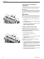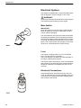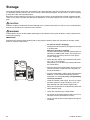
1
User guide and maintenance
manual
VOLVO
Engine
TAD1343GE
TAD1344GE
TAD1345GE
7748641
01/06/2010
33522919501_0_1
OPERATOR’S MANUAL
Generating set and industrial engines
13 liter (EMS 2)
CALIFORNIA PROPOSITION 65 WARNING
Engine exhaust, some of its constituents, and a broad range of engine parts are known to the State ofCalifornia to cause cancer, birth
defects, and other reproductive harm. Additionally, lubricants, fuels, andother fluids used in engines–including any waste created through
the wearing of engine parts–contain orproduce chemicals known to the State of California to cause cancer and birth defects or other
reproductiveharm.
Battery posts, terminals, and related accessories contain lead and lead compounds. Wash your hands afterhandling. Used engine oil
contains chemicals that have caused cancer in laboratory animals. Alwaysprotect your skin by washing thoroughly with soap and water.
Content
Foreword ...................................................................................................... 2
Safety Information ...................................................................................... 3
Introduction ................................................................................................. 7
Presentation .............................................................................................. 10
Instruments and Controls ........................................................................ 11
Starting ...................................................................................................... 18
Operation ................................................................................................... 22
Engine Shutdown ...................................................................................... 23
Fault Handling ........................................................................................... 26
Fault Code Register .................................................................................. 31
Maintenance Schedule ............................................................................. 43
Maintenance .............................................................................................. 45
Storage ....................................................................................................... 64
Technical Data ........................................................................................... 66
Operator's Manual Order .......................................................................... 73
Alphabetical index .................................................................................... 75
Foreword
Volvo Penta engines are used all over the world. They are used in all possible operating conditions. This is not a
coincidence. After 100 years as an engine manufacturer the Volvo Penta name has become a symbol of reliability,
technical innovation, top of the range performance and long service life. We also believe that this is what you
demand and expect of your Volvo Penta engine.
We would like you to read this operator’s manual thoroughly and consider the advice we give on running and
maintenance. Please pay attention to the safety instructions contained in the manual.
As owner of a Volvo Penta engine, we would also like to welcome you to a worldwide network of dealers and
service workshops to assist you with technical advice, service requirements and replacement parts. Please contact your nearest authorized Volvo Penta dealer for assistance.
You will find your closest dealer at our home page on the Internet www.volvopenta.com - amongst other
useful information about your Volvo Penta engine - we invite you to visit!
2
7748641 06-2010
Safety Information
Read the Operators Manual through very carefully before you start the engine or do any maintenance or service.
It has to do with your safety, an incorrect operation can lead to personal injury and damage to products or property.
This chapter describes how safety precaution is presented in the Operators Manual and on the product. It also
gives you an introduction to the basic safety rules for using and looking after the engine.
If there is still something which is unclear or if you feel unsure about it, please contact your Volvo Penta dealer
for assistance.
NOTICE! Check that you have received the correct operator’s manual before you read on. If not, please contact
your Volvo Penta dealer.
!
This symbol is used in the Operators Manual and on the product, to call your attention
to the fact that this is safety information. Always read such information very carefully.
Safety texts in the Operators Manual have the following order of priority:
DANGER!
Indicates a hazardous situation which, if not avoided, will result in death or serious
injury.
WARNING!
Indicates a hazardous situation which, if not avoided, could result in death or serious
personal injury.
CAUTION!
Indicates a hazardous situation which, if not avoided, could result in minor or moderate
personal injury.
IMPORTANT!
Indicates a situation which, if not avoided, could result in property damage.
NOTICE! Used to draw your attention to important information that will facilitate the
work or operation in progress.
This symbol is used on our products in some cases and refers to important information
in the Operators Manual. Make sure that warning and information symbols on the
engine are clearly visible and legible. Replace symbols which have been damaged or
painted over.
7748641 06-2010
3
Safety Information
Safety rules for operation and maintenance
Daily checks
Make it a habit to give the engine and engine bay a
visual check before starting (before the engine is
started) and after operation (once the engine has
stopped). This helps you to quickly discover whether
any leakage of fuel, coolant, oil or any other abnormal
event has happened, or is about to happen.
Starting lock
If the instrument panel does not have a key switch,
the engine room must be lockable, to prevent unauthorized persons from starting the engine. Alternatively, a lockable main switch can be used.
Carbon monoxide poisoning
Only start the engine in a well ventilated area. When
operated in a confined space, exhaust fumes and
crankcase gases must be ventilated.
Hot surfaces and fluids
A hot engine always increases the risk for burns. Be
on your guard against hot surfaces: the exhaust manifold, turbocharger, oil pan, charge air pipe, starting
heater, hot coolant and hot lubricating oil in pipes,
hoses etc.
Cooling System
Avoid opening the coolant filling cap when the engine
is hot. Steam or hot coolant can spray out and cause
scalding, at the same time as the pressure built up is
lost.
If the filler cap, coolant hose etc., still has to be opened
or removed when the engine is hot, undo the filler cap
slowly and carefully, to let the pressure out before
removing the filler cap completely and starting work.
Note that the coolant can still be hot and cause scalding.
Fuel filling
There is always a risk of fire and explosion during fuel
filling. Smoking is forbidden, and the engine should be
stopped.
Never overfill the tank. Shut the tank cap securely.
Only use the fuel recommended in the Operators
Manual. The wrong grade of fuel can cause malfunctions or stop the engine. In a diesel engine, it can also
cause the injection pump to seize and the engine will
over-rev, entailing a strong risk of personal injury and
machinery damage.
Fuel and lubrication oils
Always protect your hands when searching for leaks.
Fluids which leak under pressure can force their way
into body tissue and cause severe injury. There is a
risk of blood poisoning (septicemia).
Only use the fuel recommended in the Operators
Manual. The wrong grade of fuel can cause malfunctions or stop the engine. In a diesel engine, it can also
cause the injection pump to seize and the engine will
over-rev, entailing a strong risk of personal injury and
machinery damage.
Always cover the alternator if it is located beneath the
fuel filters. Fuel spillage can damage the alternator.
Always change the oil, oil filter and fuel filter at the
specified intervals.
Operation
The engine must not be operated in environments
which contain explosive media since none of the electrical and mechanical components are explosion
proof.
Going close to a running engine is a safety risk. Hair,
fingers, loose clothes, or dropped tools can catch on
rotating components and cause severe injury.
When engines are supplied without touch guards, all
rotating components and hot surfaces must be protected after installation in their application, if necessary for personal safety.
4
7748641 06-2010
Safety Information
Care and maintenance
Knowledge
The Operators Manual contains instructions for doing
the most common service and maintenance tasks in
a safe and correct manner. Read them carefully
before starting work.
Literature for more major tasks is available from your
Volvo Penta dealer.
Never do a job if you are not entirely sure about how
to do it. Please contact your Volvo Penta dealer and
ask for assistance instead.
Before starting
Re-install all guards which have been removed during
service work, before re-starting the engine. Make sure
that there are no tools or other objects left behind on
the engine.
Never start a turbocharged engine without the air filter
in place. The rotating compressor turbine in the turbocharger can cause severe injury. There is also a
risk that foreign bodies could be sucked in and cause
damage to the machinery.
Stopping the engine
Stop the engine before opening or removing the
engine hatch/hood. Service and maintenance work
should be done with the engine stopped unless otherwise specified.
Prevent the engine from being started by pulling out
the starter key and disconnect the power with the
main switch. Lock them in the “Off” position.
If the instrument panel does not have a key switch,
remove the system voltage with the main switch.
Fix a notice by the operator position to say that work
is in progress.
Working with, or approaching a running engine is a
safety risk. Hair, fingers, loose clothes, or dropped
tools can catch on rotating components and cause
severe injury. Volvo Penta recommends that all service work which requires the engine to be running
should be done by an authorized Volvo Penta workshop.
Lifting the engine
The lifting eyes fitted on the engine should be used
for lifting. Always check that the lifting devices are in
good condition and that they have the correct capacity
for the lift (engine weight together with auxiliaries, if
fitted). The engine should be lifted with an adjustable
lifting boom for safe handling. All chains or cables
should be parallel to each other and should be as
square as possible to the top of the engine. Please
note that auxiliary equipment installed on the engine
could change its center of gravity. Special lifting devices may then be needed to obtain the correct balance
and safe handling. Never carry out work on an engine
that is only suspended in a hoist.
Fire and explosion
Fuel and lubrication oil
All fuel, most lubricants and many chemicals are flammable. Always read and observe the advice on the
packages.
Work on the fuel system must be done with the engine
cold. Fuel leakage and spills on hot surfaces or electrical components can cause fires.
Store oil and fuel soaked rags and other flammable
material in a fireproof manner. Oil soaked rags can
self-ignite in certain circumstances.
Never smoke when filling fuel, lubrication oil or when
close to fuel filling stations or the engine bay.
Batteries
Batteries contain and give off an explosive gas, especially when charged. This gas is very flammable and
highly explosive.
Smoking, open flames or sparks must never occur in
or near to batteries or the battery locker.
Incorrect connection of a battery cable or start cable
can cause a spark which can be sufficient, in its turn,
to make the battery explode.
Spare parts
Components in fuel systems and electrical systems
on Volvo Penta engines are designed and manufactured to minimize the risk of explosions and fire, in
accordance with applicable legal requirements.
The use of spare parts not approved by Volvo Penta
can cause an explosion or fire.
Start spray
Never use start spray or similar preparations to help
in starting an engine with air pre-heating (glow plugs /
starting heater). They may cause an explosion in the
inlet manifold. Danger of personal injury.
7748641 06-2010
5
Safety Information
Electrical System
Disconnect the power
Before any work is done on the electrical system, the
engine must be stopped and the power removed by
switching off the main switch(es). Any external power
supply for engine heaters, battery chargers or other
auxiliary equipment connected to the engine must be
disconnected.
Batteries
Batteries contain a highly corrosive electrolyte. Protect your eyes, skin and clothes during charging and
other handling of batteries. Always use protective
goggles and gloves.
If acid comes into contact with your skin, wash at once
with soap and a lot of water.
If you get battery acid in your eyes, flush at once with
a lot of cold water, and get medical assistance at
once.
Electric welding
Remove the positive and negative cables from the
batteries.
Then disconnect all cables connected to the alternator. Disconnect both connectors from the engine control module.
Always connect the welder earth clamp to the component to be welded, and as close as possible to the
weld site. The clamp must never be connected to the
engine or in such a way that current can pass through
a bearing.
When welding is completed: Always connect the
cables to the alternator and engine control unit connector before reconnecting the battery cables.
6
7748641 06-2010
Introduction
This Operator's Manual refers to the industrial engines
TAD1341GE, TAD1342GE, TAD1343GE,
TAD1344GE, TAD1345GE, TAD1350GE,
TAD1351GE, TAD1352GE, TAD1353GE,
TAD1354GE, TAD1355GE, TAD1340VE,
TAD1341VE, TAD1342VE, TAD1343VE,
TAD1344VE, and TAD1345VE.
They are in-line, six-cylinder, direct injection industrial
diesel engines. All of the engines are equipped with
electronically controlled fuel management (EMS), turbocharger, charge air cooler, thermostatically controlled cooling systems and electronic speed control.
The Operator's Manual contains the information you
need to be able to operate and maintain your Volvo
Penta safely and correctly. Please read the manual
carefully and learn to handle the engine and other
equipment in a safe manner before you start the
engine.
NOTICE! The manual describes the engine and equipment sold by Volvo Penta. Differences in appearance
and function of the controls and instruments may occur
in certain variants. In these cases, please refer to the
Operator's Manual for the relevant application.
NOTICE! When ordering service or spares, always
indicate the engine and transmission identification
number. Refer to Technical Data page 71.
7748641 06-2010
7
Introduction
Warranty
Running in
Your new Volvo Penta industrial engine is covered by
a limited warranty, according to the conditions and
instructions compiled in the Warranty and Service
book.
Please note that AB Volvo Penta's liability is limited
as specified in the Warranty and Service Book. Read
it carefully, as soon as possible after delivery. It contains important information about the warranty card,
service intervals and service that the owner must be
aware of, check and perform. If this is not done, AB
Volvo Penta may disclaim its warranty obligations in
part or in full.
Please contact your Volvo Penta dealer if you
have not received a Warranty and Service book,
or a customer copy of the warranty card.
The engine must be “run in” during its first 10
hours, as follows:
Run the engine in normal operations. However, full
load may not be applied other than for short periods.
Never run the engine for an extended period of time
at constant speed during this period: this does not
apply to GE engines.
Higher oil consumption is normal during the first
100-200 hours of operation. For this reason, check the
oil level more frequently than normally recommended.
When a disengageable clutch is installed, it should be
checked more carefully during the first days. Adjustments may be necessary to compensate for bedding
in of the friction plates.
Environmental responsibility
Maintenance and replacement parts
All of us want to live in a clean, healthy environment,
where we can breathe clean air, see healthy trees,
have clean water in lakes and seas, and be able to
enjoy the sunlight without fearing for our health.
Unfortunately, this is not a matter of course these
days, but something we all must work toward.
As an engine manufacturer, Volvo Penta has special
responsibility, and for this reason environmental care
is a natural cornerstone of our product development.
Volvo Penta currently has a broad engine program in
which considerable progress has been made in
reducing exhaust emissions, fuel consumption and
engine noise etc.
We hope that you will be keen to preserve these qualities. Always follow the advice in the Operator's Manual about fuel grades, operation and maintenance, to
avoid unnecessary environmental impact. Contact
your Volvo Penta dealer if you notice any changes
such as increased fuel consumption or increased
exhaust smoke.
Remember always to hand in hazardous waste such
as drained oil, coolant, old batteries etc. for destruction at a recycling facility.
If we unite our efforts, we can make a valuable contribution to the environment together.
Volvo Penta engines are designed for maximum reliability and long life. They are built to withstand a
demanding environment, but also to have the smallest
possible environmental impact. These qualities are
retained through regular service and use of genuine
Volvo Penta parts.
Volvo Penta has a world-wide network of authorized
dealers. They are Volvo Penta product specialists,
and have the accessories, genuine parts, test equipment and special tools needed for high quality service
and repair work.
Always follow the maintenance intervals in the
manual, and remember to note the engine/transmission identification number when you order
service and replacement parts.
8
7748641 06-2010
Introduction
Certified Engines
If you own an emission-certified engine used in an
area where exhaust emissions are regulated by
law, it is important to be aware of the following:
Certification means that an engine type has been
checked and approved by the relevant authority. The
engine manufacturer guarantees that all engines of the
same type are equivalent to the certified engine.
This places special demands on the care and maintenance you provide your engine, namely:
• Maintenance and service intervals recommended
by Volvo Penta must be complied with.
• Only genuine Volvo Penta parts may be used.
• Service on injection pumps, pump settings and
injectors must always be done by an authorized
Volvo Penta workshop.
• The engine must not be converted or modified,
except with accessories and service kits which
Volvo Penta has developed for the engine.
• No installation changes to the exhaust pipe and
engine air inlet ducts may be made.
• No warranty seals (where present on the product)
may be broken by unauthorized persons.
The general instructions in the Operator's Manual concerning operation, service and maintenance apply.
NOTICE! Neglected or poorly performed care/service,
as well as the use of non-genuine spare parts, will
mean that AB Volvo Penta no longer can guarantee
that the engine conforms to the certified model.
Damages and/or costs arising from this will not be
compensated by Volvo Penta.
7748641 06-2010
9
Presentation
EMS (Engine Management
System)
EMS (Engine Management System) is an electronic system with CAN communication (Controller Area Network)
for diesel engine control. The system has been developed by Volvo Penta and includes fuel control and diagnostic
functions.
The system comprises among other things sensors, a control unit and unit injectors. The sensors send input
signals to the control unit, which in turn controls the unit injectors.
Diagnostic function
The purpose of the diagnostic function is to detect and
localize any malfunctions in the EMS system, to protect the engine and to ensure operation in the event
of serious malfunction.
If a malfunction is detected, this is announced by
warning lamps, a flashing diagnostic lamp or in plain
language on the instrument panel, depending on the
equipment used. If a fault code is obtained as a flashing code or in plain language, it is used for guidance
in any fault tracing. Fault codes can also be read by
Volvo’s VODIA tool at authorized Volvo Penta workshops.
If there is a serious malfunction, the engine will be
shut down altogether, or the control unit will reduce
the power delivered (depending on application). Once
again, a fault code is set for guidance in any fault
tracing.
Fuel control
The engine fuel requirement is analyzed up to 100
times per second. The amount of fuel injected into the
engine and the injection advance are fully electronically controlled via fuel valves and the unit injectors.
This means that the engine always receives the correct volume of fuel in all operating conditions, which
provides lower fuel consumption, minimal exhaust
emissions etc
Input signals
The control unit receives input signals about engine
operating conditions etc. from the following components:
-
coolant temperature sensor
-
charge pressure / charge temperature sensor
-
crankcase pressure sensor
-
position sensor, camshaft
-
rpm sensor, flywheel
-
coolant level sensor
-
oil level and temperature sensor
-
oil pressure sensor
-
fuel pressure sensor
-
water-in-fuel indicator
Output signals
The control module uses the input signals to control
the following components:
-
unit injectors
-
starter motor
-
main relay
-
pre-heating relay
The information from the sensors provides precise
data about prevailing operating conditions and allows
the processor in the control module to, among other
things, calculate correct injection amount, injection
timing and check the engine's condition.
10
7748641 06-2010
Instruments and Controls
DCU (Display Control Unit)
The DCU (Diesel Control System) control panel is
available as an optional accessory for the EMS
(Engine Management System) electronic control system.
The DCU is a digital instrument panel which communicates with the engine control unit. The DCU has several functions, such as engine control, monitoring,
diagnostics, and parameter setting.
The menus in the DCU system can be used to check,
and in some cases to set, a number of different functions in the EMS system.
NOTICE! The menus and illustrations shown here are
the English version. The language can be changed,
however; refer to the Setup menu.
10
9
8
7
1
2
3
5
4
6
P0002062
1
2
3
4
5
LED display
START. Starts the engine
SPEED - . Reduces engine rpm
SPEED +. Increases engine rpm
STOP. Stops the engine
6
7
8
9
10
ON/OFF. Starts and stops the system
Scroll downwards in menus
SEL. Selects in menus
Scroll upwards in menus
ESC. Return to previous menu selection
Start
When the DCU panel is started, the “Engine Data”
menu is displayed; press “ESC” to come to the main
menu.
7748641 06-2010
11
Instruments and Controls
Menus
There are several sub-menus under each main menu.
There is not space for all the menu choices on the display. To scroll through the menus, use the 7 and 9 buttons on the display. Press the SEL button 8 to make a
selection. Refer to the illustration on the previous page.
NOTICE! The Setup menu can be used to select the
language that you want to use on the display.
Main menu
• Engine data, current engine data
• Preheat, manual activation of pre-heating. Must be
activated with temperatures below 0°C (32°F)
• Governor mode. activation of droop
• Diagnostics, shows fault codes as text
• Trip reset, resets trip data
• Setup, parameter setting
• Information, shows the currently applicable hard/
software, data sets and engine identification for the
engine and DCU data
Engine data
shows relevant engine data.
• Engine speed, can be controlled with the SPEED+
and SPEED– buttons (rpm)
• Charge pressure (kPa)
• Coolant temperature (°C)
• Charge air temperature (°C)
• Oil pressure (kPa)
• Oil temperature (°C)
• Engine hours (h)
• Battery voltage (V)
• Fuel consumption (l/h)
• Instantaneous fuel consumption (trip fuel) (l)
12
7748641 06-2010
Instruments and Controls
Preheat
manual activation of pre-heating. When it is activated,
the EMS system senses at start-up if pre-heating is
needed. For automatic pre-heating, refer to the Setup /
Preheat on ignition menu.
NOTICE! Must be activated with temperatures below
0°C (32°F).
The pre-heating time is adjusted to suit the engine
temperature, and can last for up to 50 seconds both
before and after starting. Refer also to Starting procedure EMS.
• Press SEL, the text Preheat requested will be
shown
• The display automatically returns to the Engine
Data menu.
Governor mode
activates/shuts off droop. To set the droop level, refer
to the Setup / Governor gradient or Governor droop
menu.
• Select Isochronous mode or Droop mode with the
SEL button.
Diagnostics
shows the error list containing the 10 latest active and
inactive faults. The fault codes are shown as text on
the display.
• Scroll through the fault list with the arrow keys.
Trip Data reset
resets trip data, such as fuel consumption.
• Press the SEL button to reset trip data
7748641 06-2010
13
Instruments and Controls
Setup
parameter setting in the engine's control systems. Different menus appear under Customer parameter,
depending on whether Versatile or Gen set has been
selected from Set application. See below.
The parameters that can be set/selected (choice is
made with the SEL button) are:
• Set application, setting Versatile or Gen set.
Depending on the selection made here, different
menus will appear under Customer parameter.
• Unit, setting of units (metric or US imperial).
• Language, setting the language used on the display. Choose between English, French, German
and Spanish.
• Stop energized to, setting of external stop input.
Activated by Stop or Run.
Stop: The stop input must be connected to voltage
to stop the engine.
Run: The stop input must be connected to voltage
to run the engine.
• Customer parameter, setting alarm limits. Refer to
Customer parameter / Versatile and Customer
parameter / Gen set.
• Throttle input setting, setting of engine-speed
control and voltage limits. Refer to Throttle input
setting.
• Display setting, setting the display. refer to Display
setting.
Customer parameter / Versatile
• Idle engine speed - setting idle speed.
• Preheat on ignition - activation of automatic pre-
heating. The engine control system senses if preheating is needed and activates it directly at switchon.
• Governor gradient (Nm/rpm) - setting of droop
level, when activated. For activation, refer to Governor droop in the main menu.
• Oil temp warning limit (°C) - setting alarm limit for
oil temperature.
• Coolant temp warning limit (°C) - setting alarm
limit for coolant temperature.
14
7748641 06-2010
Instruments and Controls
Customer parameter / Gen set
• Primary engine speed - selection of engine rpm,
1500 or 1800 rpm.
• Preheat on ignition - activation of automatic pre-
heating. The engine control system senses if preheating is needed and activates it directly at switchon.
• Governor droop (%) - setting of droop level, when
activated. For activation, refer to “Governor droop”
in the main menu.
• Overspeed limit (%) - setting of limit for overspeed
alarm, % of set engine rpm.
• Overspeed shutdown - activation of engine shutdown with overspeed alarm. Refer to “Overspeed
limit” to activate the alarm limit for the excess rpm
alarm.
• Oil temp warning limit (°C) - setting alarm limit for
oil temperature.
• Coolant temp limit (°C) - setting alarm limit for
coolant temperature.
Throttle input setting
rpm control setting (throttle operation).
• Set throttle mode - OFF - engine rpm is controlled
via the DCU panel.
ext throttle input - engine speed is controlled with a
potentiometer (accelerator).
ext voltage input - engine rpm is controlled by an
external unit.
• Set idle voltage (V) - idle voltage level setting.
• Set max voltage (V) - full throttle voltage level setting.
7748641 06-2010
15
Instruments and Controls
Display setting
settings for the display. Adjustment is made with the
7 and 9 buttons; see DCU panel illustration.
• Set contrast (%) - contrast setting.
• Set backlight time (sec) - time setting (in seconds)
for display backlighting on, lighting is then shut off if
the panel is not used.
• Set backlight brightness - display backlighting
brightness setting.
Information
shows the data for the engine and DCU.
• Engine hardware Id - engine control unit part number.
• Engine software Id - engine control unit software
part number.
• Engine dataset1 Id - engine data set 1 part number.
• Engine dataset2 Id - engine data set 2 part number.
• Vehicle Id - chassis number.
• DCU hardware Id - DCU part number.
• DCU software Id - DCU software part number.
• DCU dataset1 Id - DCU data set 1 part number.
• DCU dataset2 Id - DCU data set 2 part number.
16
7748641 06-2010
Instruments and Controls
CIU (Control Interface Unit)
The CIU is a "translator" between the control unit
(EMS) and the customer's own control panel. The CIU
has two serial communication links, one fast and one
slow.
The fast one is a so-called CAN link. All data related to
instruments, indication lamps, connectors and potentiometers is controlled by this link.
The slow link manages diagnostic information for flashing codes etc.
P0002060
Easy Link Instruments
The following Easy Link instruments are available:
- Tachometer / hours counter (fault codes are also
displayed on the tachometer display when the diagnostic button is pressed)
- Coolant temperature
- Oil pressure
- Oil temperature
- Battery voltage
- Alarm panel
- Turbo pressure
DU (Display Unit)
The DU is an instrument panel which shows engine
working values graphically on an LCD screen. It consists of an computerized unit for permanent installation
in a control panel.
The DU is connected between the engine control unit
and the CIU or DCU.
P0002061
7748641 06-2010
17
Starting
Make it a habit of giving the engine and engine room a visual check before starting. This will help you to discover
quickly if anything abnormal has happened, or is about to happen.
Also check that instruments and warning displays show normal values after you have started the engine.
WARNING!
Never use start spray or similar products as starting aid. Explosion risk!
Before Starting
• Check that the oil level is between the MAX and MIN
marks.
NOTICE! The oil level can be read both when the
engine is stationary (the STOP side of the dipstick) and
with the engine running (the OPERATING side of the
dipstick).
For topping up please refer to the Oil level, checking
and topping up page 50.
• Open the fuel stopcocks.
STO
P
OP
ERA
TIN
G
P0004311
• Check that no leakage of oil, fuel or coolant occurs.
• Check the coolant level and that the radiator is notblocked externally. Please refer to Coolant Level,
Checking and Topping Up page 56 and Charge
Air Cooler, External Cleaning page 57
P0002078
WARNING!
Do not open the coolant filler cap when the engine
is warm, except in emergencies, this could cause
serious personal injury. Steam or hot fluid could
spray out.
• Turn the main switch(es) on.
• Move the engine speed control to idle, and disengage the clutch/gearbox if installed.
IMPORTANT!
Never disconnect the current with the main switch(es)
when the engine is running. This can damage the alternator.
18
7748641 06-2010
Starting
Starting the Engine
EMS (Engine Management System)
The pre-heating time is adjusted to suit the engine
temperature, and can last for up to 50 seconds both
before and after starting.
The starter motor connection time is maximized to 20
seconds. After that, the starter motor circuit is cut for
80 seconds to protect the starter motor against overheating.
DCU (Display Control Unit)
With pre-heating
Without pre-heating
1 Depress the ON/OFF-button (6).
1 Depress the ON/OFF-button (6).
2 Press the SEL button (8) to come to the mainmenu.
2 Press the START-button (2).
3 Scroll down to Pre/heater with scroll button
(7),press SEL-button (8)
Leave the engine to idle for the first 10 seconds. Then
warm the engine up at low speed and under low load.
Never race the engine when it is cold.
4 In the pre-heater menu, press the SEL-button
(8) to select pre-heating.
5 Press the START- button (2).
7748641 06-2010
19
Starting
Starting in Extreme Cold
Certain preparations must be made to facilitate engine
starting, and in some cases to make starting possible
at all:
• Use a winter grade fuel (of a well-known make)
which has been approved for the relevant temperature. This reduces the risk of wax deposits in the fuel
system. At extremely low temperatures, the use of
a fuel heater is recommended.
• For fully acceptable lubrication, a synthetic engine
oil of recommended viscosity for the relevant temperature should be used. Please refer to the Maintenance, lubrication system chapter. Synthetic lubricants are able to manage a wider temperature range
than mineral-based lubricants.
• Pre-heat the coolant with a separately installed ele-
tric engine heater. In extreme cases, a diesel-burning engine heater may be needed. Ask your Volvo
Penta dealer for advice.
• Make sure that the cooling system is filled with a
glycol mixture. Please refer to the Maintenance,
cooling system chapter.
• The batteries should be in good condition. Cold
weather reduces battery capacity. Increased battery
capacity may be necessary.
Never Use Start Spray
WARNING!
Never use start spray or similar products as starting
aid. Explosion risk!
P0002080
20
7748641 06-2010
Starting
Starting Using Auxiliary Batteries
WARNING!
Explosion hazard. Batteries contain and give off an
explosive gas which is highly flammable and explosive.
A short circuit, open flame or spark could cause a violent explosion. Ventilate well.
1 Check that the auxiliary batteries are connected
(series or parallel) so that the rated voltage corresponds to the engine system voltage.
2 First connect the red (+) jumper cable to the auxiliary battery, then to the flat battery. Then connect
the black (-) jumper cable to the auxiliary battery
and to a location that is somewhere away from the
discharged battery, e.g. the main switch negative
terminal or the negative terminalon the starter
motor.
3 Start the engine.
WARNING!
Do not touch the connections during the start
attempt: Risk of arcing.
Do not bend over any of the batteries either.
4 Remove the cables in the reverse order.
IMPORTANT!
The ordinary cables to the standard batteries must not
be loosened on any condition.
7748641 06-2010
21
Operation
Correct operating technique is very important for both fuel economy and engine life. Always let the engine warm
up to normal operating temperature before operating at full power. Avoid sudden throttle openings and operation
at high engine rpm.
Reading the Instruments
Check all instruments directly after starting, and then
regularly during operation.
NOTICE! On engines in continuous operation, the
lubrication oil level must be checked at least every 24
hours. Refer to Oil level, checking and topping
up page 50.
Alarms
If the EMS system receives abnormal signals from the
engine, the control unit generates fault codes and
alarms, in the form of lamps and audible warnings. This
is done by means of CAN signals to the instrument.
More information about fault codes and fault tracing
can be found in the chapter. Alarm handling.
Maneuvering
Operation at low load
Avoid long-term operation at idle or at low load, since
this can lead to increased oil consumption and eventually to oil leakage from the exhaust manifold, since
oil will seep past the turbocharger seals and accompany the induction air into the inlet manifold at low
turbo pressure.
One consequence of this is carbon build-up on valves,
piston crowns, exhaust ports and the exhaust turbine.
At low loads, the combustion temperature may
become so low that complete combustion cannot be
ensured, resulting in possible fuel dilution of lubricating
oil and eventually leakage from the exhaust manifold.
If the following points are done as a complement to
normal maintenance, there will be no risk of malfunctions caused by operation at low load.
• Reduce operation at low load to a minimum. If the
engine is regularly test-run without load once a
week, the duration of this operation should be limited to 5 minutes.
• Run the engine at full load for about 4 hours once a
year. In this way carbon deposits in the engine and
exhaust system are given the chance to burn up.
22
7748641 06-2010
Engine Shutdown
During longer breaks in operation, the engine must be warmed up at least once every two weeks. This prevents
corrosion in the engine. If you expect the engine to remain unused for two months or more, it must be laid up:
Refer to the chapter Storage page 64.
Before Engine Shutdown
Let the engine run for a few minutes without loading
before stopping it. This allows engine temperature
equalization and prevents boiling once stopped and
also allows the turbocharger to cool down. This contributes to long service life without malfunctions.
Stop the Engine
• Disengage the clutch (if possible).
• Depress the STOP-button (5).
After Engine Shutdown
1 Check the engine and engine bay for leakage.
2 Turn off the main switches before any long stoppage.
3 Carry out maintenance in accordance with the
schedule.
P0002078
For longer breaks in operation
During longer breaks in operation, the engine must be
warmed up at least once every two weeks. This prevents corrosion attacks in the engine.
If you expect the engine to be unused for two months
or more, it must be laid up. Refer to the chapter Short
Term Storage.
NOTICE! If there is a risk of frost, the coolant in the
cooling system must have sufficient frost protection.
Refer to the chapter Maintenance page 54.
A poorly-charged battery can freeze and burst; refer to
Battery, Charging page 62.
7748641 06-2010
23
Engine Shutdown
Extra Stop
For location of the extra stop, please refer to Maintenance page 46.
WARNING!
Working with or going close to a running engine is a
safety risk. Watch out for rotating components and hot
surfaces.
24
7748641 06-2010
Fault Handling
Fault Tracing
A number of symptoms and possible causes of engine malfunctions are described in the table below. Always
contact your Volvo Penta dealer if any problems occur which you can not solve by yourself.
NOTICE! Read through the safety advice for care and maintenance work in the chapter Safety Information page 3 before you start work.
Symptoms and possible causes
The diagnosis button lamp flashes
Please refer to Alarm handling
Engine can not be stopped
2, 5
Starter motor does not rotate
1, 2, 3, 4, 5, 6, 7, 24
Starter motor rotates slowly
1, 2
Starter motor rotates normally but the engine does 8, 9, 10, 11,
not start
Engine starts but stops again
8, 9, 10, 11, 13
Engine does not reach correct operating speed at 9, 10, 11, 12, 13, 21, 25, 26
full throttle
Engine runs roughly
10, 11
High fuel consumption
12, 13, 15, 25
Black exhaust smoke
12, 13
Blue or white exhaust smoke
15, 22
Too low lubrication oil pressure
16
Excessive coolant temperature
17, 18, 19, 20
Too low coolant temperature
20
No, or poor charge
2, 23
26
7748641 06-2010
Fault Handling
1 Discharged batteries
2 Poor contact/open circuit in electrical wiring
3 Main switch turned of
4 Main fuse faulty
5 Faulty ignition lock
6 Faulty main relay
7 Faulty starter motor-/solenoid
8 No fuel:
– fuel cocks closed
– fuel tank empty/wrong tank connected
9 Blocked fuel fine-filter/pre-filter (due to contaminations, or stratification in the fuel at low temperature)
10 Air in the fuel system
11 Water/contamination in fuel
12 Faulty unit injectors
13 Insufficient air supply to the engine:
– blocked air filter
– air leakage between the turbo and the engine's intake manifold
– dirty compressor part in the turbocharger
– faulty turbo compressor
– poor engine room ventilation
14 Coolant temperature too high
15 Coolant temperature too low
16 Oil level too low
17 Coolant level too low
18 Air in coolant system
19 Faulty circulation pump
20 Defective thermostat
21 Blocked charge air cooler
22 Oil level too high
23 Alternator drive belt slips
24 Water entry into engine
25 High back pressure in the exhaust system
26 Break in ”Pot+” cable to throttle
27 High temperature, charge air cooler
28 Blocked radiator
29 No pressure in cooling system
30 Check wastegate function
7748641 06-2010
27
Fault Handling
Diagnostic Function
The diagnostic function monitors and controls that the
EMS system functions normally. The diagnostic function has the following tasks:
• Detecting and locating disturbances
• Reporting detection of disturbances
• Providing guidance when fault tracing
NOTICE! With the DCU:n it is possible choose the language that the inform-tion is presented in.
If the diagnostic function detects a disturbance in the
system, this is reported using fault codes via the instruments.
Both active (unrectified) and passive (rectified) faults
are stored in the control unit.
Refer to the “Operation” heading for reading fault
codes/fault messages.
All fault codes and fault messages are found in the fault
code list, with information about the reason, reaction
and measures to be taken. Refer to Fault Code Register.
NOTICE! All instruments are optional.
Affect on engine
Engines are affected differently, depending on the
severity of the fault discovered by the diagnostic function.
A fault message in the form of a fault code is always
generated when a malfunction is discovered by the
diagnostic function.
Engines are affected differently, depending on the
severity of the fault:
• The engine is not affected
• Engine goes to idle
• Engine torque is restricted to a certain amount
• Engine is stopped
28
7748641 06-2010
Fault Handling
Active and Inactive Faults
Active faults
At the same time, the fault is stored in the control unit
memory. When the fault has been attended to and the
ignition is switched off and on again, the fault disappears as active.
Inactive faults
•
DCU – the fault is indicated as passive
•
CIU – the diagnostic lamp goes out
•
DU – the fault message disappears (inactive
faults cannot be read out)
•
Easy Link – the lamp on the alarm panel goes
out
DCU (Display Control Unit)
•
text !! ENGINE WARNING !! shown on the display.
CIU (Control Interface Unit)
•
the diagnostic lamp starts to flash.
•
”Easy Link” instrument
- the relevant lamp on the alarm panel lights up
- after the diagnostic button has been pressed,
the fault code is shown as text on the tachometer
display.
DU (Display Unit)
•
Either WARNING! or ALARM STOP (a buzzer
sounds) will be shown on the display, depending
on the severity of the fault.
•
Fault codes can also be read off using the
VODIA tool. For instructions, see “VODIA User’s
Guide”.
Operation
When a malfunction has occurred and the diagnostic
system has generated one or more fault codes, these
are read out differently depending on the equipment
used. Please refer to Fault code messages.
If the system indicates that a fault code has been
set:
1 Cut engine speed to idle, or shut the engine off.
2 For DCU/DU
Read the fault code from the display, please
refer to Reading fault codes via the DCU or
Reading fault codes via the DU.
For CIU
press the diagnostic button and read the fault
code, by observing the flashing of the diagnostic
lamp. Refer to Reading fault codes via the
diagnostic lamp, CIU.
Reading fault codes via the DU (Display Unit)
Depending on the severity of the fault the text, either
WARNING! or ALARM STOP (a buzzer sounds) will
be shown on the display
1 Press any button to come to the fault list. The
fault list shows operation hours and fault message.
2 Look up the fault code in Fault Code Register
and take the recommended measures.
3 Press on ACK to acknowledge the fault code.
The display background will change color (the
buzzer stops sounding).
4 Press on EXIT to leave the fault list.
3 Look up the fault code in the Fault Code Register chapter and take the recommended measures.
7748641 06-2010
29
Fault Handling
Reading fault causes via the DCU (Display Control
Unit)
When a fault code is set, the following text is shown
on the display:
!! ENGINE WARNING !!
alternated withPress SEL for information.
Read the fault code as follows:
1 Press SEL-button to come to the fault list.
The fault list shows:
-Operation hours
-Fault message
-Active/inactive
2 Look up the fault code in theFault Code Register chapter and take the recommended measures.
Reading fault codes via an “Easylink” instrument
When the system has discovered a malfunction, this
is reported by the diagnostic lamp which starts to
flash.
1 Press the diagnostic button. The fault code is
shown as text on the tachometer display.
2 Look up the fault code in the Fault Code Register chapter and take the recommended measures.
3 When the fault has been rectified, the fault code
disappears from the display and the diagnostic
lamp goes out.
3 Press ESC-button to leave the fault list.
NOTICE! To enter the fault list when no fault code has
been set, press the SEL button and select Diagnostics from the menu.
Reading fault codes via the diagnostic lamp on
the instrument panel, CIU
When the system has discovered a malfunction, the
diagnostic lamp starts to flash. If the diagnostic button
is depressed and then released, a fault code is
flashed out.
The fault code consists of two groups of flashes, separated by a pause of two seconds. A fault code is
obtained by counting the number of flashes in each
group
Example:
paus
= Fault Code 2.4
The fault code is stored and can be read as long as
the malfunction remains. You can find information
about cause, reaction and actions in the Fault Code
Register chapter.
Read the fault code as follows:
Erasing fault codes
Fault codes must be erased by an authorized Volvo
Penta workshop by means of the VODIA tool.
1 Press the diagnostic button.
2 Release the diagnostic button and make a note
of the fault that is flashed out.
3 Repeat items 1-2. A new fault code is flashed ou
tif more are stored. Repeat until the first fault
code is repeated.
NOTICE! When the first fault code reoccurs, all the
fault codes have been read.
If the diagnostics button is depressed after the fault
has been corrected and the fault code deleted, the
code 1.1, No fault, will be shown.
30
7748641 06-2010
Fault Code Register
No fault (Code 1.1)
Cause
There are no active faults.
Reaction
Remedy
Preheating Relay (Code 5.4, PID 45/SPN 626)
Cause
• Short circuit to positive (+) or
earth (ground) (–).
•
Open circuit.
Reaction
• Preheating can not be activated.
•
Preheating is constantly connected.
Remedy
• Check that the relay input
cable is not damaged.
•
Check relay function.
Fuel Pressure Sensor (Code 3.6, PID/SPN 94)
Cause
• Short circuit to positive (+) or
earth (ground) (–).
•
Reaction
• None
Open circuit.
Remedy
• Check that the fuel pressure
sensor connector is correctly
installed.
•
Check that the fuel pressure
sensor cable is not damaged.
•
Check that the fuel pressure
sensor is correctly installed.
•
Check fuel pressure sensor
function.
Fuel Pressure (Code 3.8, PID/SPN 94)
Cause
• Low supply pressure
Reaction
• None
Remedy
• Check if it is possible to build
up pressure with the hand
pump
•
Check the fuel filter
•
Check the fuel pre-filter
Water in Fuel (Code 2.1, PID/SPN 97)
Cause
• Water in fuel
Reaction
• None
Remedy
• Empty the primary fuel filter
Indicator for Water in Fuel (Code 2.9, PID/SPN 97)
Cause
• Short circuit
•
Open circuit
•
Fault in indicator
Reaction
• None
Remedy
• Check the indicator cables for
breaks and short circuits
•
Check indicator function.
Change indicator as necessary
Oil Level (Code 5.7, PID/SPN 98)
Cause
• Oil level to low
7748641 06-2010
Reaction
• None
Remedy
• Check the oil level
31
Fault Code Register
Oil Level Sensor (Code 5.9, PID/SPN 98)
Cause
• Shorted to plus (+) or minus
(-)
•
Reaction
• None
Break
Remedy
• Check that the cable harness
to the oil level sensor has not
been damaged
•
Check the oil level sensor
function
Oil Pressure Sensor (Code 3.1, PID/SPN 100)
Cause
• Short circuit to positive (+) or
earth (ground) (–)
•
Reaction
• None
Open circuit
Remedy
• Check that the oil pressure
sensor cable is not damaged
•
Check that the oil pressure
sensor is correctly connected
Oil Pressure (Code 6.6, PID/SPN 100)
Cause
• Oil pressure is too low
Reaction
• Engine control module
reduces engine power
(unless the protection has
been shut off with the VODIA
diagnostic tool)
Remedy
• Check oil level
•
Check that the air filter is not
blocked
•
Check system pressure
valves and safety valves in
the oil system
•
Check oil pressure sensor
function
Boost Temperature Sensor (Code 3.2, PID/SPN 105)
Cause
• Short circuit to positive (+) or
earth (ground) (–)
•
Reaction
• None
Open circuit
Remedy
• Check that the boost temperature sensor connector is correctly installed
•
Check that the boost temperature sensor cable is not damaged
•
Check that the boost temperature sensor is correctly
installed
•
Check boost temperature
sensor function
Boost Temperature (Code 6.2, PID/SPN 105)
Cause
• Boost temperature is too high
32
Reaction
• Engine control module
reduces engine power
(unless the protection has
been shut off with the VODIA
diagnostic tool)
Remedy
• Check the coolant level
•
Check the charge air cooler
(cleanliness)
•
Check boost temperature
sensor function
•
Check the function of the thermostat
7748641 06-2010
Fault Code Register
Boost Pressure Sensor (Code 3.4, PID/SPN 102/106)
Cause
• Short circuit to positive (+) or
earth (ground) (–)
•
Open circuit
Reaction
• Engine smokes more than
normally during acceleration/
load increase
Remedy
• Check that the boost pressure
sensor connector is correctly
installed
•
Check that the boost pressure
sensor cable is not damaged
•
Check that the boost pressure
sensor is correctly installed
•
Check boost pressure sensor
function
Boost Pressure Sensor (Code 3.5, PID/SPN 106)
Cause
• High charge pressure
Reaction
• Engine power is reduced or
engine stops.
Action
• Check that the charge air
pressure sensor connector is
correctly installed
•
Check that the charge air
pressure sensor cable is not
damaged
•
Check that the charge air
pressure sensor is correctly
installed
•
Check charge air temperature
sensor function
Air Filter Pressure (Code 5.5, PID/SPN 107)
Cause
• Too large pressure drop
across filter
Reaction
• Less good response from
engine
Remedy
• Check the air filter
Air Filter Sensor (Code 5.6, PID/SPN 107)
Cause
• Shorted to plus (+) or minus
(-)
•
Break
7748641 06-2010
Reaction
• None
Remedy
• Check that the air filter sensor
contact is correctly installed
•
Check that the cable harness
to air filter sensor has not
been damaged
•
Check the air filter sensor
functionality
33
Fault Code Register
Coolant Temperature Sensor (Code 3.3, PID/SPN 110)
Cause
• Short circuit to positive (+) or
earth (ground) (–)
•
Reaction
• Preheating is also activated
when the engine is hot
Open circuit
Remedy
• Check that the coolant temperature sensor connector is
correctly installed
•
Check that the coolant temperature sensor cable is not
damaged
•
Check that the coolant temperature sensor is correctly
installed
•
Check coolant temperature
sensor function
Coolant Temperature (Code 6.1, PID/SPN 110)
Cause
• Coolant temperature is too
high
Reaction
• Engine control module
reduces engine power
(unless the protection has
been shut off with the VODIA
diagnostic tool)
Remedy
• Check the coolant level
•
Check the charge air cooler
(cleanliness)
•
Check if there is air in the
cooling system
•
Check the pressure cap on
the expansion tank
•
Check coolant temperature
sensor function
•
Check thermostat function
Coolant Level (Code 2.2, PID/SPN 111)
Cause
• Low coolant level
Reaction
• Engine control module
reduces engine power
(unless the protection has
been shut off with the VODIA
diagnostic tool)
Remedy
• Check the coolant level
•
Check coolant level monitor
function
Coolant Level Sensor (Code 2.3, PID/SPN 111)
Cause
• Short circuit to positive (+)
•
Reaction
• None
Fault in sensor
Remedy
• Check that the coolant level
sensor cable is not damaged
•
Check coolant level sensor
function
Crankcase Ventilation Pressure (Code 7.7, PID/SPN 153)
Cause
• Crankcase ventilation pressure too high
34
Reaction
• The engine is shut down (if
the protection has notbeen
shut off by the parameter tool)
Remedy
• Check whether the crankcase
ventilation is blocked
•
Check whether cylinder liners, pistons or piston rings are
worn or damaged
7748641 06-2010
Fault Code Register
Crankcase Ventilation Pressure Sensor (Code 7.8, PID/SPN 153)
Cause
• Shorted to plus (+) or minus
(-)
•
Reaction
• None
Break
Remedy
• Check that the crankcase
ventilation pressure sensor
contact is correctly installed
•
Check that the cable harness
to the crankcase ventilation
pressure sensor has not been
damaged
•
Check that the crankcase
ventilation pressure sensor
correctly installed
•
Check crankcase ventilation
pressure sensor function
Battery Voltage, EMS (Code 3.9, PID/SPN 158)
Cause
• Faulty alternator
•
Reaction
• None
Faulty battery, battery cables
Remedy
• Check the supply voltage
from the control unit
Battery Voltage, CIU (Code 6.9, PID/SPN 158)
Cause
• Short circuit to negative (-)
•
Faulty alternator
•
Faulty battery, battery cables
Reaction
• Problems in engine starting
Remedy
• Check the supply voltage
from the control unit
•
Check the batteries
•
Check the alternator
•
Check the 8-pin contact
Air Temperature Sensor, Inlet (Code 7.9, PID/SPN 172)
Cause
• Shorted to plus (+) or minus
(-)
•
Reaction
• None
Break
Remedy
• Check that the air temperature sensor contact is correctly installed
•
Check that the cable harness
to the air temperature sensor
has not been damaged
•
Check that the air temperature sensor is correctly installed
•
Check the air temperature
sensor functionality
Oil Temperature Sensor (Code 3.7, PID/SPN 175)
Cause
• Shorted to plus (+) or minus
(-)
•
Break
Reaction
• None
Remedy
• Check that the cable harness
to the oil temperature sensor
has not been damaged
•
7748641 06-2010
Check that the oil temperature sensor has been connected correctly
35
Fault Code Register
Oil Temperature (Code 5.8, PID/SPN 175)
Cause
• Oil temperature is too high
Reaction
• The engine control module
limits engine output(unless
protection has been turned off
with thediagnosis tool
VODIA)
Remedy
• Check the oil level
•
Check the oil temperature
•
Check the oil temperature
sensor function
Engine Speed (Code 2.6, PID/SPN 190)
Cause
• Engine speed too high
Reaction
• None
Remedy
• After the engine has stopped,
look for the reason for the high
speed
Starter Input CIU (Code 5.2, PPID 4/SPN 520194)
Cause
• Shorted to minus (-)
•
Activated for too long
Reaction
• The engine cannot be started
•
The engine starts immediately when ignition is turned
on
Remedy
• Check that connections to the
ignition key/start panel have
not been damaged
•
Check that the cable harness
to the ignition key/start panel
has not been damaged
Stop Input CIU (Code 5.3, PPID 6/SPN 52095)
Cause
• Short circuit to negative (-)
•
Open circuit
•
Activated for too long time
Reaction
• Engine can only be stopped
with the auxiliary stop (AUX
STOP) on engine
•
Remedy
• Check that the starter switch
connections are not damaged
•
Engine stops. A fault code is
displayed for 40 seconds and
the engine can not be started
during this time. When a fault
code is active, the engine can
be started but not stopped
Check that the ignition switch
cable is not damaged
Stop Input EMS (Code 4.8, PPID 6/SPN 970)
Cause
• Short circuit to negative (-)
•
Open circuit
Reaction
• Engine can only be stopped
with the auxiliarystop
Remedy
• Check that the starter switch
connections are not damaged
Start output/Start motor relay (Code 4.6, PPID 3/ SPN 677)
Cause
• Shorted to plus (+) or minus
(-)
•
Activated for too long
Reaction
• The engine cannot be started
•
The engine starts immediately when ignition is turned
on
Remedy
• Check that connections to the
ignition key/start panel have
not been damaged
•
Check that the cable harness
to the ignition key/sart panel
has not been damaged
Piston Cooling Pressure (Code 6.7, PPID 8/SPN 520192)
Cause
• Piston cooling pressure is too
low
36
Reaction
• Engine stopped
Remedy
• Check that the oil pressure in
the engine exceeds175 kPa
(25.4 psi)
7748641 06-2010
Fault Code Register
Piston Cooling Pressure Sensor (Code 6.8, PPID 8/SPN 520192)
Cause
• Shorted to plus (+) or minus
(-)
•
Reaction
• None
Break
Remedy
• Check that the piston cooling
pressure sensor contact is
correctly installed
•
Check that the cable harness
to the piston cooling pressure
sensor has not been damaged
•
Check the piston cooling
pressure sensor functionality
Internal EGR (Code 8.5, PPID 19/SPN 2791)
Cause
• Fault in cable harness (boost
pressure sensor)
•
Reaction
• Engine control module
reduces engine power
Mechanical fault on the IEGR
Remedy
• Check cable harness (boost
pressure sensor)
•
Check the IEGR
•
Contact a Volvo Penta
authorized workshop
ECU Temperature (Code 8.4, PPID 55/SPN 1136)
Cause
• Control unit too hot, incorrect
assembly
•
Reaction
• None
Electrical fault, damaged sensor
Remedy
• Check the control unit installation. Recommended ambient temperature is 50°C
(122°F)
Speed Potentiometer Connected to CIU (Code 2.8, PPID 132/SPN 91, 608,)
Cause
• Shorted to plus (+) or minus
(-)
•
Reaction
• Engine goes to idle
•
Speed feezes
Fault in sensor
Remedy
• Check that the potentiometer
has been connected correctly
•
Check that the cable harness
to the potentiometer has not
been damaged
•
Check the potentiometer
function
SInjector, Cylinder #1 (Code 7.1, SID 1/SPN 651)
Cause
• Electrical fault
•
Faulty compression or injector
7748641 06-2010
Reaction
• Engine runs on 5 cylinders
•
Abnormal sound
•
Reduced performance
Remedy
• Check that the injector cables
are not damaged
•
Check that the injector connections are not damaged
•
Check fuel supply pressure
•
Check the valve clearance
•
Do a compression test and
check cylinder #1
37
Fault Code Register
Injector, Cylinder #2 (Code 7.2, SID 2/SPN 652)
Cause
• Electrical fault
•
Faulty compression or injector
Reaction
• Engine runs on 5 cylinders
•
Abnormal sound
•
Reduced performance
Remedy
• Check that the injector cables
are not damaged
•
Check that the injector connections are not damaged
•
Check fuel supply pressure
•
Check the valve clearance
•
Do a compression test and
check cylinder #2
Injector, Cylinder #3 (Code 7.3, SID 3/SPN 653)
Cause
• Electrical fault
•
Faulty compression or injector
Reaction
• Engine runs on 5 cylinders
•
Abnormal sound
•
Reduced performance
Remedy
• Check that the injector cables
are not damaged
•
Check that the injector connections are not damaged
•
Check fuel supply pressure
•
Check the valve clearance
•
Do a compression test and
check cylinder #3
Injector, Cylinder #4 (Code 7.4, SID 4/SPN 654)
Cause
• Electrical fault
•
Faulty compression or injector
Reaction
• Engine runs on 5 cylinders
•
Abnormal sound
•
Reduced performance
Remedy
• Check that the injector cables
are not damaged
•
Check that the injector connections are not damaged
•
Check fuel supply pressure
•
Check the valve clearance
•
Do a compression test and
check cylinder #4
Injector, Cylinder #5 (Code 7.5, SID 5/SPN 655)
Cause
• Electrical fault
•
38
Faulty compression or injector
Reaction
• Engine runs on 5 cylinders
•
Abnormal sound
•
Reduced performance
Remedy
• Check that the injector cables
are not damaged
•
Check that the injector connections are not damaged
•
Check fuel supply pressure
•
Check the valve clearance
•
Do a compression test and
check cylinder #5
7748641 06-2010
Fault Code Register
Injector, Cylinder #6 (Code 7.6, SID 6/SPN 656)
Cause
• Electrical fault
•
Faulty compression or injector
Reaction
• Engine runs on 5 cylinders
•
Abnormal sound
•
Reduced performance
Remedy
• Check that the injector cables
are not damaged
•
Check that the injector connections are not damaged
•
Check fuel supply pressure
•
Check the valve clearance
•
Do a compression test and
check cylinder #6
Camshaft Drive Speed Sensor (Code 2.5, SID21/SPN 636)
Cause
• No signal
•
Abnormal frequency
•
Fault in sensor
Reaction
• Engine takes longer to start
than normal. Engine runs normally when running
Remedy
• Check that the engine speed
sensor connector is correctly
installed
•
Check that the engine speed
sensor cable is not damaged
•
Check that the engine speed
sensor is correctly installed in
the upper timing gear cover.
•
Check engine speed sensor
function.
Flywheel Speed Sensor (Code 2.4, SID 22/SPN 637)
Cause
• No signal
•
Abnormal frequency
•
“Intermittent” signal from the
sensor
•
Fault in sensor
Reaction
• Engine is very difficult to start
and runs roughly when it
starts
Remedy
• Check that the sensor connector is correctly installed
•
Check that the engine speed
sensor cable is not damaged
•
Check that the engine speed
sensor is correctly installed in
the flywheel housing
•
Check engine speed sensor
function
Wastegate (SID 32/SPN 1188)
Cause
• Short circuit to positive (+) or
negative (-)
•
Open circuit
•
Wastegate damaged
mechanically
7748641 06-2010
Reaction
• Warning lamp lights up
•
Engine control unit limits
engine power
Remedy
• Check that the wastegate
connector is properly
mounted
•
Check that the wiring to the
wastegate is not damaged
•
Check that the wastegate is
correctly mounted
•
Check the wastegate
39
Fault Code Register
Preheating Sensor (Code 8.6, SID 70/SPN 729)
Cause
• Fault in cable harness
•
Fault in preheating relay
Reaction
• Preheating can not be activated
Remedy
• Check the cable harness
•
Check the preheating relay
Data Link (CAN), CIU (Code 6.4, SID 231/SPN 639)
Cause
• Faulty data link (CAN), , CIU
Reaction
• Instruments and warning
lamps stop working
Remedy
• Check that the 8-pin connector is not damaged
•
Check that the cables
between the CIU and the
engine management unit are
not damaged
Data Link (CAN), EMS 2 (Code 6.5, SID 231/SPN 639/2017/PSID 201)
Cause
• Internal fault in control module
Reaction
• Engine not operating: engine
can not be started. Engine
operating: engine idles and
can only be stopped with the
auxiliary stop (AUX-stop)
Remedy
• Check that the 8-pin connector is not damaged
•
Check that the cables
between the CIU and the
engine management unit are
not damaged
•
Check that sleeves 11 and 12
in the connector on the CIU
are not damaged
Power Supply to Sensor (Code 9.3, SID 211/232, SPN 1079/1080)
Cause
• Shortcut
•
Fault in sensor
Reaction
• Faulty values in oil pressure
and boost pressure sensors
•
Fault code for oil pressureand boost pressure sensor
•
Low engine output
•
The instrument shows zero oil
pressure and boost pressure
Remedy
• Check that the cable harness
to oil pressure and boost
pressure sensor has not been
damaged
•
Check oil pressure and boost
pressure sensors
Memory Fault EMS (Code 9.9, SID 240/SPN 628)
Cause
• Memory fault in engine management system
Reaction
• Engine might not start
Remedy
• Re-program the unit
Faulty data link (J1587) (Code 9.2, SID 250/SPN 608)
Cause
• Faulty data link
Reaction
• None
Remedy
• Check that the 8-pin connector is not damaged
•
40
Check that the cables
between the CIU/DCU and
the engine management unit
are not damaged
7748641 06-2010
Fault Code Register
Data Set Memory EEPROM, CIU (Code 9.8, SID 253/SPN 630)
Cause
• Internal fault in control module
•
Reaction
• Engine does not start
Remedy
• Re-program the control module.
Programming faulty
Data Set Memory EEPROM, EMS (Code 9.9, SID 253/SPN 630)
Cause
• Internal fault in control module
•
Reaction
• Engine does not start
Internal fault in control module
Remedy
• Re-program the control module. If the fault remains,
change the control module
Fault in Control Unit, CIU (Code 9.8, SID 254/SPN 629)
Cause
• Faulty EEPROM, CIU
Reaction
• CIU returns to factory setting
•
Faulty flash memory, CIU
•
Engine goes to idle
•
Fault in control module, CIU
•
Engine can not be started
Remedy
• Re- program the unit
Control Module EMS (Code 9.9, SID 254/SPN 629)
Cause
• Internal fault in control module
Reaction
• Engine misfires
•
Remedy
• Change engine control unit
Engine does not start
Injection Pressure (Code 8.3, PID/SPN 164)
Cause
• Fault in fuel supply
•
Fault in fuel pump
•
Fault in harness
•
Fault in sensor
Reaction
• Warning lamp lights up
•
Control unit reduces engine
power
Remedy
• Check harness
•
Check sensor
•
Check fuel filter
•
Check fuel pump
Fan, rpm sensor (PID 26/SPN 975)
Cause
• Open circuit
7748641 06-2010
Reaction
• Warning lamp lights up
Remedy
• Check that the fan actuator is
properly mounted
•
Check that the wiring to the
fan actuator is not damaged
•
Check that the fan actuator is
correctly mounted
•
Check the fan actuator
41
Fault Code Register
Fan actuator (SID 33/SPN 975)
Cause
• Short circuit to positive (+) or
negative (-)
Reaction
• Warning lamp lights up
Remedy
• Check that the fan actuator is
properly mounted
•
Open circuit
•
•
Fan actuator damaged
mechanically
Check that the wiring to the
fan actuator is not damaged
•
Check that the fan actuator is
correctly mounted
•
Check the fan actuator
42
7748641 06-2010
Maintenance Schedule
Service Schedule
FSI = First Service Inspection
S2 = First Time Service
S = Lubrication service
A – F = Type of service (regular service)
FSI
C = Clean
R = Replace
A = Adjustment
L = Lubrication
I = Inspect (Clean, Adjust, Lubricate or Replace if necessary)
After the first 100-200 Hours
Fuel pre-filter, draining condensed water
I
Coolant Level
I
Drive Belts
I
Start and warm up engine
Coolant/oil/fuel, leakage
I
Inspection with VODIA (Diagnostic Tool)
I
Engine and transmission, abnormal noises
I
Stop Engine
Engine Oil and Oil Filters / By-pass filter(1)(2)
R
Restart engine
Oil pressure / oil leakage
I
1) Oil change intervals vary, depending on engine type, oil grade and sulfur content of the fuel. Refer to Technical
Data page 67.
2) Change filter at every oil change.
S2
After the First 1000 Hours
Valve clearance
S
A
Every 50–600 Hours / at Least Every 12 Months
Engine Oil and Oil Filters / By-pass filter(1)(2)
R
1) Oil change intervals vary, depending on engine type, oil grade and sulfur content of the fuel. Refer to Technical
Data page 67.
2) Change the filters during each oil change.
A
Every 500 Hours / at Least Every 12th Month
Fuel Tank (sludge trap), Drain
I
Inspection with VODIA (Diagnostic Tool)
I
Fuel pre-filter, draining condensed water
I
Air Filter Inserts (Indicator), Engine
I
Radiator
I
Drive Belts
I
Batteries, electrolyte level
I
7748641 06-2010
43
Maintenance Schedule
B
Every 1000 Hours / at Least Every 12 Months
Fuel Filter
R
Air filter insert , engine
R
Fuel pre-filter
R
Coolant Filter(1)
R
1) Not at same time as coolant change.
C
Every 2000 Hours
Valve clearance
D
Every 2000 Hours / at Least Every 24th Month
Turbocharger
Turbo,
I
Wastegate(1)
I
I
Engine, with Respect to Leakage
I
Engine, with Respect to Hose and Cable Clamping
I
Engine, with Respect to Cleaning and Painting
I
Air Filter, Tank Breather
R
Air Filter, Compressor
R
1) TAD1350GE, TAD1351GE, TAD1352GE, TAD1353GE
E
Every 4000 hour / at Least Every 24 month
Belt Tensioner
I
Drive Belts
R
F
Every 8000 Hours / at Least Every 48th Month
Coolant
44
R
7748641 06-2010
Maintenance
This chapter describes how the specified maintenance points in Service Schedule page 43 should be performed,
where also service intervals are stated.
CAUTION!
Read the chapter on Maintenance before starting work. It contains instructions on how to carry out maintenance
and service operations in a safe and correct manner.
Service and maintenance work should be done with the engine stopped unless otherwise specified. Make it
impossible to start the engine by removing the system voltage with the main switch.
Working with, or approaching a running engine is a safety risk. Watch out for rotating components and hot surfaces.
Orientation
1 Expansion tank
2 Alternator
3 Oil Filler
4 Oil dipstick
5 Aux stop
6 Control panel
7 Air filter
8 Fuel filter
9 Fuel pre filter with water separator
10 Control unit, EMS
11 Turbo
12 Starter motor
13 Oil filter
14 Coolant filter
7748641 06-2010
45
Maintenance
2
1
3
8
4
7
5
6
9
14
10
13
12
11
P0004318
1. Extra stop
8. Fan, rpm sensor
2. Combined charge air pressure and charge air
temperature sensor
9. Under-pressure sensor, air filter
3. Oil pressure sensor
4. Crankcase pressure sensor
5. Water-in fuel sensor
6. Combined oil level and oil temperature sensor
10. Coolant level sensor, in the expansion tank
11. Coolant temperature sensor
12. Piston cooling pressure
13. Flywheel position and engine speed
14. Camshaft position
7. Fuel pressure sensor
46
7748641 06-2010
Maintenance
Engine, General
General inspection
Make it a habit to give the engine and engine bay a
visual inspection before starting the engine and after
operation once the engine has stopped. This will help
you to discover quickly if anything abnormal has happened, or is about to happen.
Look especially carefully at oil, fuel and coolant leakage, loose bolts, worn or poorly tensioned drive belts,
loose connections, damaged hoses and electrical
cables. This inspection only takes a few minutes and
can prevent serious malfunctions and expensive
repairs.
WARNING!
Accumulations of fuel, oil and grease on the engine or
in the engine room is a fire hazard and must be
removed immediately they are detected.
WARNING!
If an oil, fuel or coolant leak is detected, the cause must
be investigated and the fault rectified before the engine
is started.
IMPORTANT!
Remember the following when washing with a power
washer: Never aim the water jet at radiators, charge air
cooler, seals, rubber hoses or electrical components.
Air Filter, Check and Change
The engine is equipped with electronic air filter indication.
The control unit provides an output signal which is
announced as a warning on the instrument panel. The
warning indicates a pressure drop in the air filter, which
must then be checked and possibly changed.
• Scrap the old filter. No cleaning or re-use is permissible
• In continuous operation, the filter should be checked
every 8 hours. For operations in extremely dirty
environments such as coal mines and rock crushing
mills, special air filters must be used.
7748641 06-2010
47
Maintenance
Charge Air Pipe, Leakage Check
Inspect the condition of the charge air hoses, hose
unions and clamp condition for cracks and other damage. Change as necessary.
IMPORTANT!
Clamps must be tightened using a torque wrench to 9
±2 Nm (6.6 ±1.5 lbf.ft.).
P0002083
Drive Belt and Alternator Belt,
Inspection
Inspections must be carried out after operations, while
the belts are hot.
You should be able to depress the alternator belt and
the drive belt about 3-4 mm between the pulleys.
The alternator belts and drive belts have automatic belt
tensioners and do not need to be adjusted.
Check the condition of the drive belts. Replace as necessary; refer to Alternator Belts, Change page 49
and Drive Belt, Change page 49.
48
7748641 06-2010
Maintenance
Alternator Belts, Change
IMPORTANT!
Always replace a drive belt that seems worn or is
cracked.
1 Disconnect the main switch(es) and check that the
engine is not connected to system voltage.
2 Remove the fan guard and fan ring round the cooling fan.
3 Remove the belt guard.
4 Place a 1/2" square wrench in the belt tensioner (1).
Lift the wrench up and lift the water pump drive belt
off.
5 Place a 1/2" square wrench in the belt tensioner (2).
Press the wrench down and remove the alternator
belt.
6 Check that the pulleys are clean and undamaged.
7 Press the 1/2" wrench in the belt tensioner (2) down
and install the new alternator drive belt.
8 Lift the 1/2" wrench in the belt tensioner (1) and reinstall the water pump drive belt.
9 Install the belt guards.
10 Install the fan guard and fan ring round the cooling
fan.
11 Start the engine and perform a function check.
Drive Belt, Change
1 Disconnect the main switch(es) and check that the
engine is not connected to system voltage.
2 Remove the fan guard and fan ring round the cooling fan.
3 Remove the belt guard.
4 Place a 1/2" square wrench in the belt tensioner (1).
Lift the wrench and remove the drive belt.
5 Thread the drive belt round the fan and remove it.
6 Check that the pulleys are clean and undamaged.
7 Thread the new drive belt over the fan.
8 Lift the 1/2" wrench and install the new drive belt.
9 Install the belt guards.
10 Install the fan guard and fan ring round the cooling
fan.
11 Start the engine and perform a function check.
7748641 06-2010
49
Maintenance
Lubrication System
Oil change intervalls may vary according to the lubrication oil grade and fuel sulfur content. Refer to Technical data, Lubrication system.
NOTICE! Oil change intervals must never exceed a
period of 12 months.
If longer oil change intervals than those given in Technical data are required, the condition of the oil must be
checked by the oil manufacturer via regular oil tests.
P0002089
Oil level, checking and topping up
The oil level must be inside the marked area on the
dipstick and must be checked daily before the first
start.
• Top up with oil via the filler opening, please refer
to Maintenance page 45.
Check that the correct level has been achieved. If
the engine is stationary, wait for a few minutes to
allow the oil to run down into the oil pan.
• The oil level can be read both when the engine is
STO
P
OP
ERA
TIN
P0004311
G
stationary (the STOP side of the dipstick) and with
the engine running (the OPERATING side of the
dipstick).
Do not fill up above the maximum oillevel. Only use
a recommended grade of oil, please refer to Technical Data page 67.
• The oil level sensor only measures the oil level at
the time when the ignition is turned on. In other
words, not continually during operation.
50
7748641 06-2010
Maintenance
Engine Oil, Change
WARNING!
Hot oil and hot surfaces can cause burns.
Oil changes must be done when the engine is warm.
1 Connect the drain hose to the oil drain pump and
check that no leakage can occur.
2 Pump the oil out (or remove the bottom drain plug
and drain the oil).
Collect all the old oil and old filters, and leave them
at a re-cycling station for destruction.
3 Remove the drain hose (or install the bottom drain
plug).
4 Fill with engine oil.
For change volume, please refer to Technical
Data page 67.
Oil Filter/By-pass Filter, Change
2
WARNING!
Hot oil and hot surfaces can cause burns.
1 Clean the oil filter bracket (2).
2 Remove all oil filters with a suitable oil filter extractor (1).
3 Clean the mating surface of the oil filter bracket.
Make sure that no remnants of old oil seal are left
behind. Carefully clean round the inside of the protective rim (2) on the oil filter bracket.
4 Put a thin layer of engine oil on the seal rings of the
new oil filters.
1
P0004307
5 Install the new oil filters. Tighten the two full-flow
filters (on the right of the illustration) 1/2–3/4 of a
turn after they bottom. Tighten the bypass filter 3/4–
1 turn after it bottoms.
6 Top up with engine oil, start the engine and let it run
for 20-30 seconds.
7 Turn off the engine, check the oil level and top up
as required.
8 Check the sealing round the oil filters.
7748641 06-2010
51
Maintenance
Fuel System
Only use the grades of fuel recommended in the fuel
specification below, please refer to Technical
Data page 68. Always observe the greatest cleanliness during re-fueling and work on the fuel system.
IMPORTANT!
All work on the injection system of the engine must be
done by an authorized workshop.
WARNING!
Fire hazard. When carrying out work on the fuel system
make sure the engine is cold. A fuel spill onto a hot
surface or an electrical component can cause a fire.
Store fuel soaked rags so that they can not cause fire.
P0002101
Engine Fuel Filter Replacement
The fuel filter shall be replaced while the engine is cold.
WARNING!
Fire hazard. When carrying out work on the fuel system
make sure the engine is cold. A fuel spill onto a hot
surface or an electrical component can cause a fire.
Store fuel soaked rags so that they can not cause fire.
Do not fill the new fuel filter with fuel before assembly.
There is a risk that contamination could get into the
system and cause malfunctions or damage.
1 Clean round the fuel filter.
2 Remove the filter with a suitable filter remover. Collect any spilled fuel in a collection vessel.
3 Clean the filter mating surface on the filter bracket.
4 Lubricate the seal with diesel fuel and install the
new fuel filter. Tighten the fuel filter in accordance
with the instructions on the fuel filter.
5 Where necessary, purge the fuel system; refer to
Bleeding the Fuel System page 53.
6 If a water trap is installed, change the filter in it at
the same time as the fuel filter, and clean the water
trap in the plastic bowl under the filter with a soft
rag.
52
7748641 06-2010
Maintenance
Fuel Pre-filter, Change
1 Undo the cable from the water trap sensor.
2 Remove the water trap filter from the filter bracket.
Collect any spilled fuel in a collection vessel.
3 Remove the lower part of the water trap from the
filter.
4 Clean the lower part of the water trap with a soft rag.
Check that the drain hole in the lower part is not
blocked.
5 Install a new seal on the lower part and lubricate the
seal with diesel fuel. Re-install the lower part of the
filter.
6 Lubricate the seal with diesel fuel. Screw the filter
onto the filter bracket by hand until the rubber seal
just touches the mating surface. Then tighten a further half turn, no more.
7 Connect the cable to the water trap sensor.
8 Where necessary, purge the fuel system; refer to
Bleeding the Fuel System page 53.
Draining condensate, fuel system
1 Put a collection vessel under the fuel filter to collect
the condensate and fuel.
2 Open the drain nipple (1) in the base of the fuel prefilter.
3 Tighten the drain tap (1) when fuel without water
starts to run out.
1
P0004327
Bleeding the Fuel System
The system does not need to be purged unless it has
been run completely dry. Purging is then done with the
hand pump on the fuel filter bracket.
7748641 06-2010
53
Maintenance
Cooling System
The engine's internal cooling system makes sure the
engine works at the right temperature. It is a closed
system that must always be filled with a mixture of
concentrated coolant and water in order to protect the
engine against internal corrosion, cavitation and freeze
bursting.
IMPORTANT!
Coolant of a suitable chemical composition must be
used all year round. This also applies in areas where
there is never any risk of freezing, to provide the engine
full corrosion protection.
The corrosion protection additives become less effective over time, which means that the coolant must be
changed at regular intervals; refer to the Service
Schedule page 43. The cooling system must be
flushed whenever the coolant is changed; refer to the
Cooling System, Cleaning page 59 section.
Volvo Penta engines are delivered with either “Volvo
Penta Coolant” (green) or “Volvo Penta Coolant VCS”
(yellow); both are available as concentrates and
“Ready Mixed”.
Volvo Penta coolants have been prepared to work best
with Volvo Penta engines and offer excellent protection
against corrosion, cavitation damage, and bursts due
to freezing. Only coolants of this quality are adapted
to, and approved by, Volvo Penta.
We recommend that the coolant supplied with the
engine on delivery be used. Future warranty claims
related to engine and accessories may be declined if
an unsuitable coolant has been used, or if the instructions for coolant mixture have not been followed.
The use of anti-corrosion agents alone is not permitted
in Volvo Penta engines. Never use water alone as a
replacement for coolant.
IMPORTANT!
• The two types of Volvo Penta coolant may never be
mixed with each other as this will affect the anti-corrosion properties.
• Coolant filters may not be used together with Volvo
Penta Coolant VCS.
• Engines using yellow Volvo Penta Coolant VCS
must have a yellow decal with the text VOLVO
COOLANT VCS on the expansion tank.
Ready Mixed
Ready mixed coolant contains 40% Volvo Penta Coolant / Volvo Penta Coolant VCS and 60% water. This
mixture protects against internal corrosion, cavitation
and bursts due to freezing down to –28 °C (–18 °F).
54
7748641 06-2010
Maintenance
Coolant, Mixing
The concentrated coolant must be mixed with pure
water (distilled or de-ionized water) according to specifications; refer to Water Quality page 70.
WARNING!
All coolant is hazardous and harmful to the environment. Do not consume. Coolant is flammable.
IMPORTANT!
Different kinds of coolant must not be mixed with each
other!
Mix: 40% concentrated coolant and 60% water
This mixture protects against internal corrosion, cavitation and bursts due to freezing down to –28°C (–
18°F). A 60% glycol admix lowers the freezing point to
-54 °C (-65 °F).
Never mix more than 60% concentrate in the coolant.
A greater concentration provides reduced cooling
effect with the risk for overheating and reduced antifreeze protection.
It is extremely important that the system be filled with
the correct coolant concentration. Mix in a separate
clean vessel before filling the cooling system. Make
sure that the liquids mix.
7748641 06-2010
55
Maintenance
Coolant Level, Checking and
Topping Up
Coolant filling must be performed with the engine stopped. Check the coolant level daily before starting.
IMPORTANT!
Only use the coolant recommended by Volvo Penta.
Top up with the same type of coolant as already used
in the system. Different types of coolant must not be
mixed.
1
WARNING!
2
Do not open the coolant filler cap when the engine is
warm, except in emergencies, this could cause serious
personal injury. Steam or hot fluid could spray out.
1 Only open the filler cap (1). Do not open the pressure cap (2).
2 Check that the coolant level is above the MIN mark
on the expansion tank.
P0002095
3 Top up with coolant as required, so that the level is
between the MIN and MAX marks.
Fill slowly, to allow air to flow out.
Filling a completely empty system
NOTICE! Mix the correct amount of coolant in
advance, to ensure that the cooling system is completely filled. Refer to Technical Data, Cooling System,
for the correct coolant volume.
Do not open the pressure cap (2).
1 Check that all drain points are closed.
1
2
2 Open filler cap (1).
3 Fill with coolant, so that the level is between the MIN
and MAX marks.
Fill slowly, to allow air to flow out.
NOTICE! Do not start the engine until the system is
vented and completely filled.
P0002095
4 Start the engine when the cooling system has been
completely filled and vented. Open any venting taps
a short while after starting, to allow trapped air to
escape.
If a heating unit is connected to the engine cooling
system, the heat control valve must be opened and
the installation vented during filling.
5 Stop the engine after about an hour and check the
coolant level. Top up as necessary.
56
7748641 06-2010
Maintenance
Coolant, Draining
WARNING!
Do not open the coolant filler cap when the engine is
warm, except in emergencies, this could cause serious
personal injury. Steam or hot fluid could spray out.
IMPORTANT!
On engines which are to be laid up or put in storage,
the engine cooling system must not be drained. The
coolant contains corrosion-inhibiting additives.
1 Stop the engine.
1
2
2 Remove the filler cap (1). Do not open the pressure
cap (2).
3 Open all drain points. Drain the coolant from the
radiator and engine block, using the drain hose.
The drain nipples are situated under the radiator on
the right side of the engine block.
P0002095
4 Check that all coolant drains out. Deposits may be
found inside the drain plug/tap, and need to be
cleared away. There is otherwise a risk that coolant
could remain and cause frost damage. Check
whether the installation has any further taps or
plugs at the lowest points of the cooling water pipes.
5 Shut any taps and check that the spring-loaded
covers on the nipples close completely. Install the
rubber plugs.
Charge Air Cooler, External
Cleaning
Remove guards as necessary, to access the cooler.
Clean with water and a mild detergent. Use a soft
brush. Be careful not to damage the radiator matrix.
Re-install the components.
IMPORTANT!
Do not use a high pressure power washer.
7748641 06-2010
57
Maintenance
Coolant Filter, Change
NOTICE! Only applies to engines using Volvo Penta
Coolant (green). Engines using Volvo Penta Coolant
VCS are not fitted with coolant filters.
Open
1 Turn the tap (1) 90° to stop the flow through the
coolant filter.
2 Remove the coolant filter with a suitable extractor.
Make sure that no residue from the old seal remains
in the housing.
3 Put a thin layer of engine oil on the new coolant filter
seal. Screw the coolant filter on by hand until the
seal comes into contact with the mating surface of
the filter bracket. Then tighten the coolant filter a
further 1/2 turn.
4 Turn the tap (1) 90° to release the flow through the
coolant filter again.
5 Start the engine and carry out a leakage check.
6 Switch the engine off and check the coolant level.
Refer to Coolant Level, Checking and Topping
Up page 56.
Closed
58
7748641 06-2010
Maintenance
Cooling System, Cleaning
Cooling performance is reduced by deposits in the
radiator and cooling galleries. The cooling system
should be cleaned out when the coolant is changed.
IMPORTANT!
Cleaning must not be done if there is any risk of the
cooling system freezing, since the cleaning solution
does not have any frost prevention ability.
IMPORTANT!
It is extremely important that the correct concentration
and volume of coolant is put in the system. Mix in a
separate clean vessel before filling the cooling system.
Make sure that the liquids mix.
1 Empty the cooling system. Refer to Coolant, Draining page 57.
2 Put a hose into the expansion tank filling hole and
flush with clean water, as specified by Volvo Penta–
refer to section Water quality in Technical
Data page 70 until the water draining out is completely clear.
3 If there should still be some contamination left after
flushing for a long time, cleaning can be done with
coolant. Otherwise, continue as in item 8 below.
4 Fill the cooling system with 15-20 % mixture of concentrated coolant. Use only Volvo Penta recommended concentrated coolant mixed with clean
water.
5 Drain the coolant after 1-2 days of operation.
Remove the filler cap and possibly the lower radiator hose to increase the speed of emptying.
To prevent suspended material from settling back
in the system, emptying should be done rapidly,
within the space of 10 minutes, when the engine
has not been standing still for a long time.
6 Flush the system immediately and thoroughly with
clean hot water to prevent dirt from settling in the
inner areas. Flush until the water that runs out is
completely clean. Make sure that any heater controls are set to full heating during emptying.
7 If contamination should still be left after a long
period of flushing, you can do a cleanout with Volvo
Penta radiator cleaner, followed by finishing-off with
Volvo Penta neutralizer. Carefully follow the
instructions on the package. Otherwise, continue
as in item 8 below.
8 When the cooling system is completely free from
contamination, close the drain taps and plugs.
9 Fill up with Volvo Penta recommended coolant, following the instructions in the chapters entitled
Maintenance page 54and Coolant Level, Checking
and Topping Up page 56.
7748641 06-2010
59
Maintenance
Electrical System
The engine is equipped with a 2-pole electrical system
and an alternator. System voltage is 12V or 24V.
WARNING!
Always stop the engine and break the current using the
main switches before working on the engine.
Main Switch
IMPORTANT!
Never disconnect the current with the main switches
when the engine is running, the alternator and electronics could be damaged.
The main switches must never be switched off before
the engine has stopped. If the circuit between the alternator and the battery is disconnected when the engine
is running, the alternator and electronics can be damaged. For the same reason the charging circuits must
never be re-connected with the engine running.
Fuses
The engine is equipped with a 10 A circuit breaker
which cuts the current if overloaded.
The circuit breaker is located on the left-hand side of
the engine Maintenance page 46.
The engine stops if the fuse trips. If the circuit breaker
trips frequently, an authorized Volvo Penta workshop
should be contacted to investigate the cause of the
overload.
Electrical Connections
Check that electrical connections are dry, free from
oxide, and that they are securely tightened. Spray the
connections as necessary with water-repellent spray
(Volvo Penta universal oil).
60
7748641 06-2010
Maintenance
Battery, Maintenance
WARNING!
Risk of fire and explosion. Never allow an open flame
or electric sparks near the battery or batteries.
WARNING!
P0002107
Never confuse the positive and negative poles on the
batteries. Risk of arcing and explosion.
WARNING!
The battery electrolyte contains extremely corrosive
sulfuric acid. Protect your skin and clothes when charging or handling batteries.
Always use protective goggles and gloves. If battery
electrolyte comes into contact with unprotected skin
whas off immediately using plenty of water and soap.
If battery acid comes in contact with the eyes, flush
immediately with plenty of water and obtain medical
assistance without delay.
Connecting and disconnecting the battery
Connecting
-
1 Connect the + cable (red) to the + pole on the battery.
+
2 Connect the – cable (black) to the – pole on the
battery.
Disconnecting
1 Remove the – cable (black).
2 Remove the + cable (red).
P0002108
Cleaning
Keep the batteries clean and dry. Contamination and
oxide on the batteries and battery poles can cause
stray currents, voltage drop and discharge, especially
in wet weather. Remove oxidation from the battery
poles and terminals, using a brass brush. Tighten the
terminals securely and grease them with terminal
grease or petroleum jelly.
7748641 06-2010
61
Maintenance
Filling
The electrolyte level should be 5–10 mm (0.2– 0.4”)
above the cell plates in the battery. Top up with distilled
water as required.
After filling, the battery should be charged for at least
30 minutes by running the engine at idle.
Some maintenance-free batteries have special
instructions, which must be followed.
P0002110
Battery, Charging
WARNING!
Risk of fire and explosion. Never allow an open flame
or electric sparks near the battery or batteries.
P0002107
WARNING!
The battery electrolyte contains extremely corrosive
sulfuric acid. Protect your skin and clothes when charging or handling batteries.
Always use protective goggles and gloves. If battery
electrolyte comes into contact with unprotected skin
whas off immediately using plenty of water and soap.
If battery acid comes in contact with the eyes, flush
immediately with plenty of water and obtain medical
assistance without delay.
WARNING!
Never confuse the positive and negative poles on the
batteries. Risk of arcing and explosion.
IMPORTANT!
Observe the instruction manual for the battery charger
carefully. To avoid the risk of electrochemical corrosion
when an external charger is connected, the battery
cables should be removed from the batteries before
the charger is connected.
Always switch off the charging current before the
charging clips are removed.
62
7748641 06-2010
Maintenance
• Charge batteries if they have become discharged.
During charging, unscrew the cell plugs but leave
them in the plug holes. Ventilate well, especially if
the batteries are charged in an enclosed space.
• If the engine is not used for a longer period of time,
the batteries should be fully charged, then possibly
trickle charged (please refer to the battery manufacturer’s recommendations). Batteries are damaged by being left discharged, and can also freeze
and burst easier in cold weather.
• Special instructions apply to boost charging. Boost
charging can shorten battery life, and should therefore be avoided.
P0002111
7748641 06-2010
63
Storage
The engine and other equipment must be laid up to prevent damage if they are not used for two months or more.
It is important that this is done in the correct manner, and nothing is forgotten. For this reason, we have compiled
a check list of the most important points.
Before the engine is taken out of service for a long period of time, an authorized Volvo Penta workshop should
check it over. Have any faults and deficiencies attended to, so that the equipment is in order, ready for the next
start.
CAUTION!
Read the chapter on Maintenance before starting work. It contains instructions on how to carry out maintenance
and service operations in a safe and correct manner.
WARNING!
Conservations oils can be flammable and dangerous to breathe. Ensure good ventilation. Use a protective face
mask when spraying.
IMPORTANT!
Remember the following when washing with a high pressure washer: Never aim the water jet at seals, rubber
hoses or electrical components.
• For up to 8 month’s stoppage:
Change the oil and oil filter on the engine, then warm
it up afterwards.
More than 8 month's stoppage:
Conserve the lubrication and fuel systems with conservation oil. Please refer section Conservation of
the lubrication and fuel systems for more than 8
months’ stoppage:.
• Check that the coolant offers sufficient frost protection. Top up as necessary.
Alternatively, you can drain the coolant (also drain
the coolant filter).
• Drain any water and contamination from the fuel filters and fuel tank. Fill the fuel tank completely, to
avoid condensation.
• Disconnect the battery cables, clean and charge the
batteries. Trickle charge the batteries while the
equipment is in storage.A poorly charged battery
can freeze and burst.
P0002089
• Clean the outside of the engine. Do not use a high
pressure washer for engine cleaning. Touch up
paint damage with Volvo Penta original paint.
• Spray the components of the electrical system with
water-repellent spray.
• Check and rust-proof any control cables.
• Put a note on the engine with the date, type of conservation and the conservation oil used.
• Cover over the air filter, exhaust pipe and engine if
necessary.
64
7748641 06-2010
Storage
Bringing out of storage
•
Remove any covers from the engine, air filter
and exhaust pipe.
•
Put the correct grade of oil into the engine, if
necessary, refer to Tekniska data, smörjsystem. Install a new oil filter if the filter was not
changed during conservation.
•
Install new fuel filters and vent the fuel system.
•
Check the drive belt(s).
•
Check the condition of all rubber hoses, and
retighten the hose clamps.
•
Close the drain taps and install any drainplugs.
•
Check the coolant level. Top up as necessary.
•
Connect the fully charged batteries.
•
Start the engine and warm it up at fast idle with
no loading.
•
Check that no oil, fuel or coolant leakage occurs.
Conservation of the lubrication and fuel systems for more than 8 months’ stoppage:
• Drain the engine oil and fill up with conservation
• Start the engine and run at a fast idle until about 2
oil* to just over the MIN marking on the dipstick.
liters (0.6 US gals) of the fluid in the jerrican have
been used. Stop the engine and connect the ordi• Connect the fuel suction and return hoses to a 1/3
nary fuel pipes.
full jerrican containing conservation oil* and 2/3
diesel fuel.
• Drain the engine’s conservation oil.
•
Vent the fuel system.
•
Follow the other instructions on the previous page.
* Conservation oils are sold by oil companies.
7748641 06-2010
65
Technical Data
Engines
Type designation
TAD1341/42/43/44/45GE
Power, Prime/Stand-by
Refer to the sales literature
Torque, Prime/Stand-by
Refer to the sales literature
No. of cylinders
6
Cylinder diameter mm/inches
131/5.16
Stroke, mm/inches
158/6.22
Cylinder volume,
dm3/in3
12,78/779.7
Wet weight (engine only), kg/lb
1325/2921
Wet weight (incl. cooling system, air filter and frame), kg/lb
1790/3946
Firing order
1-5-3-6-2-4
Compression ratio
18,1:1
Low idle, rpm
900
High idle, rpm
1500/1800
Type designation
TAD1350/51/52/53/54/55GE
Power, Prime/Stand-by
Refer to the sales literature
Torque, Prime/Stand-by
Refer to the sales literature
No. of cylinders
6
Cylinder diameter mm/inches
131/5.16
Stroke, mm/inches
158/6.22
Cylinder volume,
dm3/in3
12,78/779.7
Dry weight (excl. cooling system), kg/lb
1295/2855
Wet weight (excl. cooling system), kg/lb
1325/2921
Firing order
1-5-3-6-2-4
Compression ratio
18.1:1
Low idle, rpm
900
High idle, rpm
1800
Type designation
TAD1340/41/42/43/44/45VE
Power, Prime/Stand-by
Refer to the sales literature
Torque, Prime/Stand-by
Refer to the sales literature
No. of cylinders
6
Cylinder diameter mm/inches
131/5.16
Stroke, mm/inches
158/6.22
Cylinder volume,
dm3/in3
12,78/779.7
Wet weight (engine only), kg/lb
1325/2921
Wet weight (Power Pac), kg/lb
1790/3946
Firing order
1-5-3-6-2-4
Compression ratio
18.1:1
Idle, rpm
600–1200
66
7748641 06-2010
Technical Data
Lubrication System
Oil
Change volume, including filter change, liter/US gal
36 / 9.5
Oil pressure, hot engine
at operating speed, kPa/psi
370-520 / 54–75
at idle, min, kPa
250 / 39
Oil filter
Full flow filter
2
By-pass filter
1
Lube oil pump
Type
Gear driven
Oil recommendations
Sulfur content in fuel, by weight
up to 0.5 %
Oil garde
0.5 – 1.0 %
more than 1.0 % 1)
Oil change interval: Reached first in operation:
VDS-3
600 hrs / 12 month
300 hrs / 12 month
150 hrs / 12 month
VDS-2 and ACEA: E7 2)
VDS-2 and ACEA: E5 2)
VDS-2 and Global DHD-1 2)
VDS-2 and API: CI-4 2)
VDS-2 and API: CH-4 2)
400 hrs / 12 month
200 hrs / 12 month
100 hrs / 12 month
VDS and ACEA: E3 2)
200 hrs / 12 month
100 hrs / 12 month
50 hrs / 12 month
NOTICE! Mineral based oil, as well as fully or semi-synthetic, can be used on condition that it complies with the
quality requirements above.
1) If sulfur content is > 1.0 % by weight, use oil with TBN > 15.
2) Lubrication oil must comply with both requirements. Note API: CG-4 or CH-4 can be approved in markets outside Europe (instead of ACEA
E3).ACEA E3).
VDS = Volvo Drain Specification
ACEA = Association des Constructeurs Européenne d’Automobiles
API = American Petroleum Institute Global
DHD = Global Diesel Heavy Duty
TBN = Total Base Number
7748641 06-2010
67
Technical Data
Viscosity
Select the viscosity from the adjacent table, for the
appropriate continuous ambient air temperature.
*Refers to synthetic or semi-synthetic oils
Fuel System
Feed pump
Feed pressure at 600 rpm
min 100 kPa (14.5 psi)
Feed pressure at 1200 rpm
min 300 kPa (43,5 psi)
Feed pressure at full load
min 300 kPa (43,5 psi)
Bypass valve
Opening pressure
400-550 kPa (58–80 psi)
Fuel specification
The fuel must comply with national and international standards for commercially supplied fuels, such as:
EN 590 (with nationally adapted environmental and cold weather requirements)
ASTM D 975 No 1-D och 2-D
JIS KK 2204
Sulfur content: Complying with legal requirements in each country. If the sulfur content exceeds 0.5 weightpercent, the oil change intervals shall be changed, refer to Technical Data page 67.
Extremely low sulfur content fuel (urban diesel in Sweden and city diesel in Finland) can cause a loss of up to 5
% of power and an increase in fuel consumption of about 2-3 %.
Biodiesel
Biodiesel is also known as Fatty Acid Methyl Esters (FAME).
Volvo Penta accepts max 5% FAME in diesel fuel, in accordance with EN590, to be used without any restraint in
service recommendations.
Volvo Penta accepts extended FAME use up to 30% blend in diesel fuel for engines produced after Jan 1-2009,
under specific conditions and with certain limitations. Specific service requirements are applied for fuel blends
with more than 5% FAME.
Engines that are manufactured by Volvo Penta are certified for the use of market diesel fuel according to EN 590.
Emission requirements according to EU Stage 3A will only be met with the prescribed EN 590 diesel fuel. At the
date of this document En 590 diesel fuel may contain up to 5% FAME.
68
7748641 06-2010
Technical Data
Conditions
Volvo Penta engines of above are able to run with fuel blends containing up to 30% FAME under specific conditions:
• Oil quality VDS-3 or VDS-4 must be used.
• FAME must comply with EN 14214(1).
• Diesel fuel in which FAME is mixed must comply with EN 590(2).
• Specific service requirements must be fulfilled. See Service Bulletin 18-8-8, contact your Volvo Penta service
dealer.
The fuel must comply with nationally laws and regional/local provisions regarding the use of FAME. The engine
operator has the responsibility of using the fuel that is recommended by the manufacturer and allowed by the
national legislation.
Normal rapeseed oil and other pure vegetable and animal oils do not meer EN 14214 and may not be used as
fuel or as fuel additives. These products are not approved by Volvo Penta and warranties do not apply in the event
of engine damage.
1) European standard that describes the quality requirements and test methods for FAME.
2) European standard that describes the quality requirements and test methods for Diesel.
Performance
The energy value of FAME is lower than for standard diesel fuel. The use of 30% FAME can result in an increase
in fuel consumption with up to 5% and decrease maximum power performance by up to 4%. The engine fuel
consumption data is only valid for diesel and will give incorrect readings if FAME blends are used.
Predictive maintenance on oil drain is not applicable. The exhaust fumes might smell different and visible smoke
might be seen during starting when using FAME.
7748641 06-2010
69
Technical Data
Cooling System
Type
Preassurized, sealed
Pressure cap, max opening pressure, kPa/psi
70 / 10.2
Volume (engine), liter US gal
20 / 5.28
Volume (engine+radiator and hoses), liter/US gal
24 / 6,34
Thermostat
Number
1 pcs
Opening temperature
82° C / 180° F
Water Quality
ASTM D4985:
P0002094
Total solid particles
<340 ppm
Total hardness
<9.5° dH
Chloride
<40 ppm
Sulfate
<100 ppm
pH value
5.5–9
Silica (acc. ASTM D859)
<20 mg SiO2/l
Iron (acc. ASTM D1068)
<0.10 ppm
Manganese (acc. ASTM D858)
<0.05 ppm
Conductivity (acc. ASTM D1125)
<500 µS/cm
Organic content, CODMn (acc.
ISO8467)
<15 mg KMnO4/l
Electrical System
System voltage
24V
Alternator
voltage/max. current
28V/80A
power app.
2200W
Battery capacity
2 pcs. series connected 12 V, max. 225 Ah
Battery electrolyte specific gravity at +25 °C:
fully charged battery
1.28 g/cm3 (1.24 g/cm3)*
batteriet omladdas vid
1.20 g/cm3 (1.20 g/cm3)*
* Note. Applies to batteries with tropical acid.
70
7748641 06-2010
Technical Data
Identification Numbers
3
2
1
P0002050
1
Chassis and serial number
P0002051
2
A Engine designation
A
B
C
D
E
F
G
P0002052
B Engine power, net, (without fan)
C Max. engine speed
D Main software
E Dataset 1
F Dataset 2
G Product number
3
1 Engine designation
2 Serial number
P0002053
7748641 06-2010
3 Specification number
71
Declaration for the installation of partially-completed machinery in accordance with
Machinery Directive 2006/42/EC
Engine Manufacturer:
AB Volvo Penta
Gropegårdsgatan
SE 405 08 Göteborg
Sweden
Description of engine: 4-cycle diesel engine
Engine types covered by this declaration:
TAD1341GE
TAD1342GE
TAD1343GE
TAD1344GE
TAD1345GE
TAD1350GE
TAD1351GE
TAD1352GE
TAD1353GE
TAD1354GE
TAD1355GE
TAD1340VE
TAD1341VE
TAD1342VE
TAD1343VE
TAD1344VE
TAD1345VE
Fundamental health and safety requirements applied to, and fulfilled by, the above-mentioned engines are described in the
following items in Annex I; 1.1.3, 1.1.5, 1.5.1, 1.5.2, 1.5.3, 1.5.4, 1.5.6, 1.5.13, 1.6.1, 1.6.2, 1.6.4, 1.7.1, 1.7.1.1, 1.7.1.2,
1.7.4, 1.7.4.1 and 1.7.4.3.
The relevant technical documentation is compiled as described in part B of Annex VII.
Relevant information concerning the partially-completed machinery will be provided in suitable form upon justified requests
from competent national authorities. The individual authorized to compile the relevant technical documentation is the signer
of this declaration.
The harmonizing standards applied are:
EN ISO 12100-1: Safety of machinery - Basic concepts, general principles for design - Part 1: Basic terminology, methodology
EN ISO 12100-2: Safety of machinery - Basic concepts, general principles for design - Part 2: Technical principles
EN 1679-1: Reciprocating internal combustion engines - Safety - Part 1: Compression ignition engines
The partially-completed machinery also complies with the following relevant Directive:
2004/108/EC - Electromagnetic Compatibility (EMC) Directive
Applied Standards: EN 61000-6-1, EN 61000-6-2, EN 61000-6-3, EN 61000-6-4, EN 12895, EN-ISO 14982 and EN 13309
These engines may not be put into operation before the completed machinery into which they are to be installed has been
declared to conform with the provisions of Machinery Directive 2006/42/EC.
Name and function: Tom Tveitan, Laws and Regulation
Signature and title:
(the identity of the individual authorized to sign on behalf of the
engine manufacturer or the latter's authorized representative).
Date and place of issue: (yyyy/mm/dd) 2009/12/29 Gothenburg
PL-06/09
Operator's Manual Order
This Operator’s Manual may be ordered in a different
language free of charge up to 12 months after delivery,
via internet.
Please refer to the link below. On the web page, type
in the publication number found in the bottom of this
page (7–8 digits).
http://vppneuapps.volvo.com/manual/coupon/
If internet access isn't possible, please contact your
Volvo Penta dealer.
All order information is stored internally at AB Volvo
Penta and will not be shared with third parties.
7748641 06-2010
73
Alphabetical index
After Engine Shutdown.........................................
Air Filter, Check and Change..................................
Alarms.....................................................................
Alternator Belts, Change.........................................
23
47
22
49
Battery, Charging..................................................
Battery, Maintenance..............................................
Before Engine Shutdown.........................................
Before Starting........................................................
Bleeding the Fuel System.......................................
62
61
23
18
53
Charge Air Cooler, External Cleaning.................
Charge Air Pipe, Leakage Check............................
CIU (Control Interface Unit).....................................
Coolant Filter, Change............................................
Coolant Level, Checking and Topping Up...............
Coolant, Draining.....................................................
Cooling System, Cleaning.......................................
57
48
17
58
56
57
59
DCU (Display Control Unit)............................. 11, 19
Declaration of Conformity........................................ 72
Diagnostic Function................................................. 28
Draining condensate, fuel system........................... 53
Drive Belt and Alternator Belt, Inspection................ 48
Drive Belt, Change.................................................. 49
DU (Display Unit)..................................................... 17
Easy Link Instruments.......................................... 17
Electrical Connections............................................. 60
EMS (Engine Management System)................. 10, 19
Engine Fuel Filter Replacement.............................. 52
Engine Oil, Change................................................. 51
Engine, General...................................................... 47
Engines................................................................... 66
Extra Stop................................................................ 24
Fault Tracing.......................................................... 26
Fuel Pre-filter, Change............................................ 53
Fuel System...................................................... 52, 68
Identification Numbers......................................... 71
Lubrication System......................................... 50, 67
Main Switch............................................................ 60
Maneuvering............................................................ 22
Never Use Start Spray........................................... 20
Oil Filter/By-pass Filter, Change.......................... 51
Oil level, checking and topping up........................... 50
Orientation............................................................... 45
Reading the Instruments...................................... 22
Service Schedule...................................................
Starting in Extreme Cold.........................................
Starting the Engine..................................................
Starting Using Auxiliary Batteries............................
Stop the Engine.......................................................
43
20
19
21
23
Water Quality......................................................... 70
7748641 06-2010
75
© 2010 AB VOLVO PENTA
Volvo reserves the right to make changes
Printed on environmentally friendly paper
7748641 English 06-2010